EP0919726A1 - Vacuum pumps - Google Patents
Vacuum pumps Download PDFInfo
- Publication number
- EP0919726A1 EP0919726A1 EP98309555A EP98309555A EP0919726A1 EP 0919726 A1 EP0919726 A1 EP 0919726A1 EP 98309555 A EP98309555 A EP 98309555A EP 98309555 A EP98309555 A EP 98309555A EP 0919726 A1 EP0919726 A1 EP 0919726A1
- Authority
- EP
- European Patent Office
- Prior art keywords
- pump
- stages
- interstage
- inlet
- vacuum
- Prior art date
- Legal status (The legal status is an assumption and is not a legal conclusion. Google has not performed a legal analysis and makes no representation as to the accuracy of the status listed.)
- Granted
Links
Images
Classifications
-
- F—MECHANICAL ENGINEERING; LIGHTING; HEATING; WEAPONS; BLASTING
- F04—POSITIVE - DISPLACEMENT MACHINES FOR LIQUIDS; PUMPS FOR LIQUIDS OR ELASTIC FLUIDS
- F04D—NON-POSITIVE-DISPLACEMENT PUMPS
- F04D19/00—Axial-flow pumps
- F04D19/02—Multi-stage pumps
- F04D19/04—Multi-stage pumps specially adapted to the production of a high vacuum, e.g. molecular pumps
Definitions
- This invention relates to improved vacuum pumps with particular reference to those employing a turbo-molecular mode of operation.
- a conventional turbo-molecular stage arrangement of a vacuum pump comprises a stack of alternate rotors and stators.
- Each stage effectively comprises a solid disc with a plurality of blades depending (nominally) radially therefrom; the blades are evenly spaced around the circumference of the disc and angled "about" radial lines out of the plane of the disc in the direction of rotation of the rotor stage.
- the rotor and stator blades have positive and negative gradients respectively when viewed from the side in a radial line from the disc. This arrangement has the effect in molecular flow conditions of causing the movement of molecules through the pump.
- the throughput of gas from the different parts of the apparatus will generally vary also.
- the detector and analyser may be evacuated by separate turbo-molecular vacuum pumps which themselves need to be backed by separate pumps, for example rotary vane pumps.
- a single backing pump is relatively common for supporting two (or more) turbo-molecular pumps.
- turbo-molecular pump it has more recently been proposed to employ a single turbo-molecular pump to replace two (or more) individual pumps with the single pump having a normal inlet for gas required to pass through all the stages of the pump and an intermediate inlet, i.e. between the stages, for gas required to pass through only the latter stages of the pump.
- a vacuum pump comprising a plurality of vacuum stages and having a first pump inlet through which gas can pass through all the pump stages and a second inlet through which gas can enter the pump at an interstage location and pass only through subsequent stages of the pump, wherein the pump stages prior to the interstage are sized differently to those stages subsequent to the interstage such that the pump overall suits the pressure requirement / pumping capacity of the different systems attended to the first and second inlets respectively.
- the invention has advantageous application to turbo-molecular pumps in particular.
- the stages prior to the interstage can be of a smaller size than those stages subsequent to the interstage.
- turbo-molecular pumps in particular, it is preferred that there are three, four, five, six or more stages (rotor/stator pairs) both before and after the pump interstage.
- one or more Holweck pump stages are employed between the final turbo-molecular stage and the pump outlet.
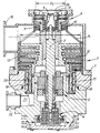
- a vacuum pump having a multi-component body 1 within which is mounted a shaft 2. Rotation of the shaft 2 is effected by means of a motor generally indicated at 3 positioned about the shaft 2. The position of the shaft 2 is controlled by bearings at its base generally indicated at 4 and at its top generally indicated at 5, all of design well known in the art.
- the pump possesses two sets of turbo-molecular stages generally indicated at 6 and 7 before and after an interstage therebetween respectively.
- the first set of turbo-molecular stages comprises four rotors (impellers) of angled blade construction as described above and of known construction, one of which is indicated at 8 and four corresponding stators again of angled blade construction and again as described above and of known construction, one of which is indicated at 9 in the drawing.
- the tip diameter D 1 of the rotors is indicated in the drawing.
- An inlet 10 to the first set of stages allows gas entry through a perforated inlet screen 11 in to the four rotor/stator stages of the first set.
- a second set of turbo-molecular stages 7 comprises a further six rotors (impellers) of angled blade construction, one of which is indicated at 12 and six corresponding stators again of angled blade construction, one of which is indicated at 13 in the drawing.
- the tip diameter D 2 of these rotors is also indicated in the drawing.
- stator bridge 14 of heavily perforated design.
- Gas exiting from the first set 6 of turbo-molecular stages can pass through the interstage area and into the second set 7 of turbo-molecular stages.
- a second inlet 16 is formed in the pump body 1 and allows entry of gas directly in to the interstage area via the apertures in the stator bridge 14.
- Holweck stages comprise two rotating cylinders 17, 18 and corresponding annular stators 19, 20 having helical channels formed therein (on one side for stator 19, on both sides for stator 20) all in a general manner known per se .
- Gas exiting the Holweck stage is urged into a passageway 21 found in the pump body 1 and thence to a pump outlet 22.
- the sets of turbo-molecular pump stages are therefore sized to reflect the pressure requirements and pumping capacities of the respective vacuum systems to be attached to the inlet 1 and to the inlet 2 thereby leading to overall pump improvements in terms of lower power consumption and smaller size.
Landscapes
- Engineering & Computer Science (AREA)
- Mechanical Engineering (AREA)
- General Engineering & Computer Science (AREA)
- Non-Positive Displacement Air Blowers (AREA)
Abstract
Description
- This invention relates to improved vacuum pumps with particular reference to those employing a turbo-molecular mode of operation.
- A conventional turbo-molecular stage arrangement of a vacuum pump comprises a stack of alternate rotors and stators. Each stage effectively comprises a solid disc with a plurality of blades depending (nominally) radially therefrom; the blades are evenly spaced around the circumference of the disc and angled "about" radial lines out of the plane of the disc in the direction of rotation of the rotor stage.
- The rotor and stator blades have positive and negative gradients respectively when viewed from the side in a radial line from the disc. This arrangement has the effect in molecular flow conditions of causing the movement of molecules through the pump.
- There a number of types of apparatus where a plurality of chambers needs to be evacuated down to different levels of vacuum. For example, in well known types of mass spectrometer that part of the apparatus known as the detector commonly has to be operated at, say 10-6 mbar whereas that part known as the analyser has to be operated at a different level of vacuum, say 10-3 .
- In addition and importantly, the throughput of gas from the different parts of the apparatus will generally vary also. For example in a typical mass spectrometer of the type discussed above, there may need to be a 60 l/second capacity for the detector and a 200 l/second capacity for the analyser.
- In apparatus of the type including but not restricted to mass spectrometers, a number of different vacuum pumps are normally employed. For example, in mass spectrometers, the detector and analyser may be evacuated by separate turbo-molecular vacuum pumps which themselves need to be backed by separate pumps, for example rotary vane pumps.
- There is an ever increasing need to rationalise the use of the various vacuum pumps for overall reduced apparatus size and power requirements. A single backing pump is relatively common for supporting two (or more) turbo-molecular pumps. In addition, it has more recently been proposed to employ a single turbo-molecular pump to replace two (or more) individual pumps with the single pump having a normal inlet for gas required to pass through all the stages of the pump and an intermediate inlet, i.e. between the stages, for gas required to pass through only the latter stages of the pump.
- However, even these proposals for rationalisation of the apparatus pumping system do not overcome all the problems associated with size and power consumption in particular.
- There is therefore a need for improved vacuum pumps in which rationalisation can be further enhanced.
- In accordance with the invention, there is provided a vacuum pump comprising a plurality of vacuum stages and having a first pump inlet through which gas can pass through all the pump stages and a second inlet through which gas can enter the pump at an interstage location and pass only through subsequent stages of the pump, wherein the pump stages prior to the interstage are sized differently to those stages subsequent to the interstage such that the pump overall suits the pressure requirement / pumping capacity of the different systems attended to the first and second inlets respectively.
- The invention has advantageous application to turbo-molecular pumps in particular.
- In terms of suiting the pressure requirements of the different systems, that system requiring the lower pressure (higher vacuum) will generally need to be attached to the first inlet so that gas being evacuated is subject to all the stages of the pump whereas that system requiring the higher pressure (lower vacuum) will generally need to be attached to the second inlet so that gas being evacuated is subject only to the pump stage subsequent to the interstage.
- In those cases, for example, in which the system needing the lower pressure (high vacuum) requires a smaller pumping capacity in terms, in particular, of speed and compression and, for example, in which the system needing the higher pressure requires a higher pumping capacity, the stages prior to the interstage can be of a smaller size than those stages subsequent to the interstage.
- In the case of a turbo-molecular pump in particular, this means that the tip diameter of the rotor is smaller in the stages before the interstage than after the interstage.
- In the case of turbo-molecular pumps in particular, it is preferred that there are three, four, five, six or more stages (rotor/stator pairs) both before and after the pump interstage.
- In preferred embodiments associated with a turbo-molecular pump, one or more Holweck pump stages are employed between the final turbo-molecular stage and the pump outlet.
- For a better understanding of the invention, reference will now be made to the accompanying drawing which shows a vertical sectional view through a vacuum pump of the invention employing a turbo-molecular mode of operation and also including final Holweck stages.
- With reference to the drawing, there is shown a vacuum pump having a multi-component body 1 within which is mounted a
shaft 2. Rotation of theshaft 2 is effected by means of a motor generally indicated at 3 positioned about theshaft 2. The position of theshaft 2 is controlled by bearings at its base generally indicated at 4 and at its top generally indicated at 5, all of design well known in the art. - The pump possesses two sets of turbo-molecular stages generally indicated at 6 and 7 before and after an interstage therebetween respectively.
- The first set of turbo-molecular stages comprises four rotors (impellers) of angled blade construction as described above and of known construction, one of which is indicated at 8 and four corresponding stators again of angled blade construction and again as described above and of known construction, one of which is indicated at 9 in the drawing.
- The tip diameter D1 of the rotors is indicated in the drawing.
- An
inlet 10 to the first set of stages allows gas entry through aperforated inlet screen 11 in to the four rotor/stator stages of the first set. - A second set of turbo-molecular stages 7 comprises a further six rotors (impellers) of angled blade construction, one of which is indicated at 12 and six corresponding stators again of angled blade construction, one of which is indicated at 13 in the drawing.
- The tip diameter D2 of these rotors is also indicated in the drawing.
- At an interstage position between the first and second sets of turbo-molecular stages is positioned a
stator bridge 14 of heavily perforated design. - Gas exiting from the
first set 6 of turbo-molecular stages can pass through the interstage area and into the second set 7 of turbo-molecular stages. - A
second inlet 16 is formed in the pump body 1 and allows entry of gas directly in to the interstage area via the apertures in thestator bridge 14. - At the exit of the second set 7 of turbo-molecular stages is a number of Holweck stages. These Holweck stages comprise two rotating
cylinders annular stators stator 19, on both sides for stator 20) all in a general manner known per se. - Gas exiting the Holweck stage is urged into a
passageway 21 found in the pump body 1 and thence to apump outlet 22. - In this embodiment, the sets of turbo-molecular pump stages are therefore sized to reflect the pressure requirements and pumping capacities of the respective vacuum systems to be attached to the inlet 1 and to the
inlet 2 thereby leading to overall pump improvements in terms of lower power consumption and smaller size.
Claims (7)
- A vacuum pump comprising a plurality of vacuum stages and having a first pump inlet through which gas can pass through all the pump stages and a second inlet through which gas can enter the pump at an interstage location and pass only through subsequent stages of the pump, wherein the pump stages prior to the interstage are sized differently to these stages subsequent to the interstages such that the pump overall suits the pressure requirements / pumping capacity of the different systems attached to the first and second inlet respectively.
- A vacuum pump according to Claim 1 which is a turbo-molecular vacuum pump.
- A vacuum pump according to Claim 1 or Claim 2 in which a system requiring a lower pressure is attached to the first inlet and a system requiring a higher pressure is attached to the second inlet.
- A vacuum pump according to any preceding claim in which the pump stages prior to the interstage are of a smaller size than those stages subsequent to he interstage.
- A vacuum pump according to Claim 4 in which the pump is a turbo-molecular pump and the tip diameter of the rotor is smaller in the stages before the interstage than after the interstage.
- A vacuum pump according to any one of Claims 2 to 5 having a least three turbo-molecular stages both before and after the interstage.
- A vacuum pump according to any one of Claims 2 to 6 in which a Holweck stage is employed between the final turbo-molecular stage and the pump outlet.
Applications Claiming Priority (2)
| Application Number | Priority Date | Filing Date | Title |
|---|---|---|---|
| GBGB9725146.6A GB9725146D0 (en) | 1997-11-27 | 1997-11-27 | Improvements in vacuum pumps |
| GB9725146 | 1997-11-27 |
Publications (2)
| Publication Number | Publication Date |
|---|---|
| EP0919726A1 true EP0919726A1 (en) | 1999-06-02 |
| EP0919726B1 EP0919726B1 (en) | 2004-02-04 |
Family
ID=10822765
Family Applications (1)
| Application Number | Title | Priority Date | Filing Date |
|---|---|---|---|
| EP98309555A Revoked EP0919726B1 (en) | 1997-11-27 | 1998-11-23 | Vacuum pumps |
Country Status (5)
| Country | Link |
|---|---|
| US (1) | US6106223A (en) |
| EP (1) | EP0919726B1 (en) |
| JP (1) | JP4395210B2 (en) |
| DE (1) | DE69821453T2 (en) |
| GB (1) | GB9725146D0 (en) |
Cited By (17)
| Publication number | Priority date | Publication date | Assignee | Title |
|---|---|---|---|---|
| EP1085214A2 (en) | 1999-09-16 | 2001-03-21 | The BOC Group plc | Vacuum pumps |
| GB2360066A (en) * | 2000-03-06 | 2001-09-12 | Boc Group Plc | Vacuum pump |
| EP1302667A1 (en) * | 2001-10-15 | 2003-04-16 | The BOC Group plc | Vacuum pumps |
| WO2005033521A1 (en) * | 2003-09-30 | 2005-04-14 | The Boc Group Plc | Vacuum pump |
| WO2006048603A1 (en) * | 2004-11-01 | 2006-05-11 | The Boc Group Plc | Vacuum pump |
| WO2010097384A2 (en) | 2009-02-28 | 2010-09-02 | Oerlikon Leybold Vacuum Gmbh | Multi-inlet vacuum pump |
| EP2273128A1 (en) | 2004-06-25 | 2011-01-12 | Edwards Limited | Vacuum pump |
| WO2019229462A1 (en) * | 2018-05-31 | 2019-12-05 | Micromass Uk Limited | Bench-top time of flight mass spectrometer |
| US11355331B2 (en) | 2018-05-31 | 2022-06-07 | Micromass Uk Limited | Mass spectrometer |
| US11367607B2 (en) | 2018-05-31 | 2022-06-21 | Micromass Uk Limited | Mass spectrometer |
| US11373849B2 (en) | 2018-05-31 | 2022-06-28 | Micromass Uk Limited | Mass spectrometer having fragmentation region |
| US11437226B2 (en) | 2018-05-31 | 2022-09-06 | Micromass Uk Limited | Bench-top time of flight mass spectrometer |
| US11476103B2 (en) | 2018-05-31 | 2022-10-18 | Micromass Uk Limited | Bench-top time of flight mass spectrometer |
| US11538676B2 (en) | 2018-05-31 | 2022-12-27 | Micromass Uk Limited | Mass spectrometer |
| US11621154B2 (en) | 2018-05-31 | 2023-04-04 | Micromass Uk Limited | Bench-top time of flight mass spectrometer |
| US12009193B2 (en) | 2018-05-31 | 2024-06-11 | Micromass Uk Limited | Bench-top Time of Flight mass spectrometer |
| US12027359B2 (en) | 2018-05-31 | 2024-07-02 | Micromass Uk Limited | Bench-top Time of Flight mass spectrometer |
Families Citing this family (23)
| Publication number | Priority date | Publication date | Assignee | Title |
|---|---|---|---|---|
| DE19821634A1 (en) * | 1998-05-14 | 1999-11-18 | Leybold Vakuum Gmbh | Friction vacuum pump with staged rotor and stator |
| JP3961155B2 (en) * | 1999-05-28 | 2007-08-22 | Bocエドワーズ株式会社 | Vacuum pump |
| DE19951954A1 (en) * | 1999-10-28 | 2001-05-03 | Pfeiffer Vacuum Gmbh | Turbomolecular pump |
| DE10008691B4 (en) * | 2000-02-24 | 2017-10-26 | Pfeiffer Vacuum Gmbh | Gas friction pump |
| DE10111546A1 (en) * | 2000-05-15 | 2002-01-03 | Pfeiffer Vacuum Gmbh | Gas friction pump |
| JP3777498B2 (en) * | 2000-06-23 | 2006-05-24 | 株式会社荏原製作所 | Turbo molecular pump |
| JP2002138987A (en) * | 2000-10-31 | 2002-05-17 | Seiko Instruments Inc | Vacuum pump |
| DE10056144A1 (en) * | 2000-11-13 | 2002-05-23 | Pfeiffer Vacuum Gmbh | Gas friction pump |
| US6503050B2 (en) * | 2000-12-18 | 2003-01-07 | Applied Materials Inc. | Turbo-molecular pump having enhanced pumping capacity |
| DE10142567A1 (en) * | 2001-08-30 | 2003-03-20 | Pfeiffer Vacuum Gmbh | Turbo molecular pump |
| DE10150015A1 (en) * | 2001-10-11 | 2003-04-17 | Leybold Vakuum Gmbh | Multiple chamber plant used for degassing, coating or etching substrates comprises an evacuating system connected to chambers |
| GB0229352D0 (en) * | 2002-12-17 | 2003-01-22 | Boc Group Plc | Vacuum pumping arrangement and method of operating same |
| GB0409139D0 (en) * | 2003-09-30 | 2004-05-26 | Boc Group Plc | Vacuum pump |
| GB0411426D0 (en) * | 2004-05-21 | 2004-06-23 | Boc Group Plc | Pumping arrangement |
| US7140833B2 (en) * | 2004-11-04 | 2006-11-28 | The Boc Group, Llc | Integrated turbo/drag/regenerative pump with counter-rotating turbo blades |
| GB0503946D0 (en) * | 2005-02-25 | 2005-04-06 | Boc Group Plc | Vacuum pump |
| US7927066B2 (en) * | 2005-03-02 | 2011-04-19 | Tokyo Electron Limited | Reflecting device, communicating pipe, exhausting pump, exhaust system, method for cleaning the system, storage medium storing program for implementing the method, substrate processing apparatus, and particle capturing component |
| DE102008024764A1 (en) * | 2008-05-23 | 2009-11-26 | Oerlikon Leybold Vacuum Gmbh | Multi-stage vacuum pump |
| GB0901872D0 (en) * | 2009-02-06 | 2009-03-11 | Edwards Ltd | Multiple inlet vacuum pumps |
| CN103201520B (en) * | 2010-11-24 | 2017-02-08 | 埃地沃兹日本有限公司 | Protective mesh for vacuum pump and vacuum pump with same |
| GB2558921B (en) * | 2017-01-20 | 2020-06-17 | Edwards Ltd | A multiple stage turbomolecular pump with inter-stage inlet |
| GB2601515B (en) | 2020-12-02 | 2022-12-28 | Agilent Technologies Inc | Vacuum pump with elastic spacer |
| EP4293232A1 (en) * | 2023-10-17 | 2023-12-20 | Pfeiffer Vacuum Technology AG | Pump |
Citations (5)
| Publication number | Priority date | Publication date | Assignee | Title |
|---|---|---|---|---|
| DE2442614A1 (en) * | 1974-09-04 | 1976-03-18 | Siemens Ag | Rotary high vacuum pump - has second inlet opening so that it can produce two levels of vacuum |
| US4140441A (en) * | 1977-04-11 | 1979-02-20 | Patterson Williams G | Turbomolecular pump lubrication system |
| EP0072892A1 (en) * | 1981-08-26 | 1983-03-02 | Leybold-Heraeus GmbH | Turbo-molecular pump suited for completion of counterflow leak indication |
| EP0603694A1 (en) * | 1992-12-24 | 1994-06-29 | BALZERS-PFEIFFER GmbH | Vacuum system |
| EP0731278A1 (en) * | 1995-03-10 | 1996-09-11 | Balzers-Pfeiffer GmbH | Molecular vacuum pump with cooling gas device |
Family Cites Families (2)
| Publication number | Priority date | Publication date | Assignee | Title |
|---|---|---|---|---|
| JPH05195957A (en) * | 1992-01-23 | 1993-08-06 | Matsushita Electric Ind Co Ltd | Vacuum pump |
| US5501583A (en) * | 1992-08-19 | 1996-03-26 | Hitachi, Ltd. | Turbo vacuum pump |
-
1997
- 1997-11-27 GB GBGB9725146.6A patent/GB9725146D0/en not_active Ceased
-
1998
- 1998-11-23 DE DE69821453T patent/DE69821453T2/en not_active Expired - Lifetime
- 1998-11-23 EP EP98309555A patent/EP0919726B1/en not_active Revoked
- 1998-11-24 US US09/199,178 patent/US6106223A/en not_active Expired - Lifetime
- 1998-11-27 JP JP33686898A patent/JP4395210B2/en not_active Expired - Lifetime
Patent Citations (5)
| Publication number | Priority date | Publication date | Assignee | Title |
|---|---|---|---|---|
| DE2442614A1 (en) * | 1974-09-04 | 1976-03-18 | Siemens Ag | Rotary high vacuum pump - has second inlet opening so that it can produce two levels of vacuum |
| US4140441A (en) * | 1977-04-11 | 1979-02-20 | Patterson Williams G | Turbomolecular pump lubrication system |
| EP0072892A1 (en) * | 1981-08-26 | 1983-03-02 | Leybold-Heraeus GmbH | Turbo-molecular pump suited for completion of counterflow leak indication |
| EP0603694A1 (en) * | 1992-12-24 | 1994-06-29 | BALZERS-PFEIFFER GmbH | Vacuum system |
| EP0731278A1 (en) * | 1995-03-10 | 1996-09-11 | Balzers-Pfeiffer GmbH | Molecular vacuum pump with cooling gas device |
Cited By (25)
| Publication number | Priority date | Publication date | Assignee | Title |
|---|---|---|---|---|
| EP1085214A3 (en) * | 1999-09-16 | 2002-04-03 | The BOC Group plc | Vacuum pumps |
| EP1085214A2 (en) | 1999-09-16 | 2001-03-21 | The BOC Group plc | Vacuum pumps |
| GB2360066A (en) * | 2000-03-06 | 2001-09-12 | Boc Group Plc | Vacuum pump |
| EP1302667A1 (en) * | 2001-10-15 | 2003-04-16 | The BOC Group plc | Vacuum pumps |
| US6709228B2 (en) | 2001-10-15 | 2004-03-23 | The Boc Group Plc | Vacuum pumps |
| WO2005033521A1 (en) * | 2003-09-30 | 2005-04-14 | The Boc Group Plc | Vacuum pump |
| CN100429405C (en) * | 2003-09-30 | 2008-10-29 | 英国爱德华兹有限公司 | Vacuum pump |
| US8393854B2 (en) | 2003-09-30 | 2013-03-12 | Edwards Limited | Vacuum pump |
| EP2273128A1 (en) | 2004-06-25 | 2011-01-12 | Edwards Limited | Vacuum pump |
| WO2006048603A1 (en) * | 2004-11-01 | 2006-05-11 | The Boc Group Plc | Vacuum pump |
| US8206081B2 (en) | 2004-11-01 | 2012-06-26 | Edwards Limited | Vacuum pump |
| DE102009011082A1 (en) | 2009-02-28 | 2010-09-02 | Oerlikon Leybold Vacuum Gmbh | Multi-inlet vacuum pump |
| WO2010097384A2 (en) | 2009-02-28 | 2010-09-02 | Oerlikon Leybold Vacuum Gmbh | Multi-inlet vacuum pump |
| US8926266B2 (en) | 2009-02-28 | 2015-01-06 | Oerlikon Leybold Vacuum Gmbh | Multi-inlet vacuum pump |
| US11367607B2 (en) | 2018-05-31 | 2022-06-21 | Micromass Uk Limited | Mass spectrometer |
| US11355331B2 (en) | 2018-05-31 | 2022-06-07 | Micromass Uk Limited | Mass spectrometer |
| WO2019229462A1 (en) * | 2018-05-31 | 2019-12-05 | Micromass Uk Limited | Bench-top time of flight mass spectrometer |
| US11373849B2 (en) | 2018-05-31 | 2022-06-28 | Micromass Uk Limited | Mass spectrometer having fragmentation region |
| US11437226B2 (en) | 2018-05-31 | 2022-09-06 | Micromass Uk Limited | Bench-top time of flight mass spectrometer |
| US11476103B2 (en) | 2018-05-31 | 2022-10-18 | Micromass Uk Limited | Bench-top time of flight mass spectrometer |
| US11538676B2 (en) | 2018-05-31 | 2022-12-27 | Micromass Uk Limited | Mass spectrometer |
| US11621154B2 (en) | 2018-05-31 | 2023-04-04 | Micromass Uk Limited | Bench-top time of flight mass spectrometer |
| US11879470B2 (en) | 2018-05-31 | 2024-01-23 | Micromass Uk Limited | Bench-top time of flight mass spectrometer |
| US12009193B2 (en) | 2018-05-31 | 2024-06-11 | Micromass Uk Limited | Bench-top Time of Flight mass spectrometer |
| US12027359B2 (en) | 2018-05-31 | 2024-07-02 | Micromass Uk Limited | Bench-top Time of Flight mass spectrometer |
Also Published As
| Publication number | Publication date |
|---|---|
| DE69821453D1 (en) | 2004-03-11 |
| EP0919726B1 (en) | 2004-02-04 |
| JPH11230085A (en) | 1999-08-24 |
| US6106223A (en) | 2000-08-22 |
| GB9725146D0 (en) | 1998-01-28 |
| DE69821453T2 (en) | 2004-12-02 |
| JP4395210B2 (en) | 2010-01-06 |
Similar Documents
| Publication | Publication Date | Title |
|---|---|---|
| US6106223A (en) | Multistage vacuum pump with interstage inlet | |
| EP1302667B1 (en) | Vacuum pumps | |
| JP5053842B2 (en) | Pumping device | |
| EP1668255B1 (en) | Vacuum pump | |
| EP0775829A1 (en) | Turbomolecular vacuum pumps | |
| US5238362A (en) | Turbomolecular pump | |
| EP0445855A1 (en) | Improved turbomolecular pump | |
| EP1085214B1 (en) | Vacuum pumps | |
| US5611660A (en) | Compound vacuum pumps | |
| JP2002515568A (en) | Friction vacuum pump with stator and rotor | |
| US4732530A (en) | Turbomolecular pump | |
| GB2360066A (en) | Vacuum pump | |
| US6626639B2 (en) | Vacuum pump | |
| US20220170471A1 (en) | Vacuum Pump with Elastic Spacer | |
| JPH03213695A (en) | Turbo vacuum pump | |
| JPH07189984A (en) | Multistage circumferential flow vacuum pump |
Legal Events
| Date | Code | Title | Description |
|---|---|---|---|
| PUAI | Public reference made under article 153(3) epc to a published international application that has entered the european phase |
Free format text: ORIGINAL CODE: 0009012 |
|
| AK | Designated contracting states |
Kind code of ref document: A1 Designated state(s): CH DE FR GB LI |
|
| AX | Request for extension of the european patent |
Free format text: AL;LT;LV;MK;RO;SI |
|
| 17P | Request for examination filed |
Effective date: 19991008 |
|
| AKX | Designation fees paid |
Free format text: CH DE FR GB LI |
|
| 17Q | First examination report despatched |
Effective date: 20020702 |
|
| GRAH | Despatch of communication of intention to grant a patent |
Free format text: ORIGINAL CODE: EPIDOS IGRA |
|
| GRAP | Despatch of communication of intention to grant a patent |
Free format text: ORIGINAL CODE: EPIDOSNIGR1 |
|
| GRAS | Grant fee paid |
Free format text: ORIGINAL CODE: EPIDOSNIGR3 |
|
| GRAA | (expected) grant |
Free format text: ORIGINAL CODE: 0009210 |
|
| AK | Designated contracting states |
Kind code of ref document: B1 Designated state(s): CH DE FR GB LI |
|
| REG | Reference to a national code |
Ref country code: GB Ref legal event code: FG4D |
|
| REG | Reference to a national code |
Ref country code: CH Ref legal event code: EP |
|
| REF | Corresponds to: |
Ref document number: 69821453 Country of ref document: DE Date of ref document: 20040311 Kind code of ref document: P |
|
| REG | Reference to a national code |
Ref country code: CH Ref legal event code: NV Representative=s name: RIEDERER HASLER & PARTNER PATENTANWAELTE AG |
|
| PLBQ | Unpublished change to opponent data |
Free format text: ORIGINAL CODE: EPIDOS OPPO |
|
| PLBI | Opposition filed |
Free format text: ORIGINAL CODE: 0009260 |
|
| PLBQ | Unpublished change to opponent data |
Free format text: ORIGINAL CODE: EPIDOS OPPO |
|
| PLBI | Opposition filed |
Free format text: ORIGINAL CODE: 0009260 |
|
| ET | Fr: translation filed | ||
| PLAX | Notice of opposition and request to file observation + time limit sent |
Free format text: ORIGINAL CODE: EPIDOSNOBS2 |
|
| 26 | Opposition filed |
Opponent name: LEYBOLD VACUUM GMBH Effective date: 20041028 |
|
| 26 | Opposition filed |
Opponent name: VARIAN INC. Effective date: 20041102 Opponent name: LEYBOLD VACUUM GMBH Effective date: 20041028 |
|
| PLAX | Notice of opposition and request to file observation + time limit sent |
Free format text: ORIGINAL CODE: EPIDOSNOBS2 |
|
| PLBB | Reply of patent proprietor to notice(s) of opposition received |
Free format text: ORIGINAL CODE: EPIDOSNOBS3 |
|
| REG | Reference to a national code |
Ref country code: GB Ref legal event code: 732E |
|
| REG | Reference to a national code |
Ref country code: CH Ref legal event code: PUE Owner name: EDWARDS LIMITED Free format text: THE BOC GROUP PLC#CHERTSEY ROAD#WINDLESHAM SURREY GU20 6HJ (GB) -TRANSFER TO- EDWARDS LIMITED#MANOR ROYAL#CRAWLEY WEST SUSSEX RH10 9LW (GB) |
|
| RAP2 | Party data changed (patent owner data changed or rights of a patent transferred) |
Owner name: EDWARDS LIMITED |
|
| PGFP | Annual fee paid to national office [announced via postgrant information from national office to epo] |
Ref country code: CH Payment date: 20071129 Year of fee payment: 10 |
|
| REG | Reference to a national code |
Ref country code: FR Ref legal event code: TP |
|
| REG | Reference to a national code |
Ref country code: CH Ref legal event code: PL |
|
| PG25 | Lapsed in a contracting state [announced via postgrant information from national office to epo] |
Ref country code: LI Free format text: LAPSE BECAUSE OF NON-PAYMENT OF DUE FEES Effective date: 20081130 Ref country code: CH Free format text: LAPSE BECAUSE OF NON-PAYMENT OF DUE FEES Effective date: 20081130 |
|
| PLAB | Opposition data, opponent's data or that of the opponent's representative modified |
Free format text: ORIGINAL CODE: 0009299OPPO |
|
| R26 | Opposition filed (corrected) |
Opponent name: AGILENT TECHNOLOGIES, INC. Effective date: 20041102 Opponent name: LEYBOLD VACUUM GMBH Effective date: 20041028 |
|
| APBM | Appeal reference recorded |
Free format text: ORIGINAL CODE: EPIDOSNREFNO |
|
| APBP | Date of receipt of notice of appeal recorded |
Free format text: ORIGINAL CODE: EPIDOSNNOA2O |
|
| APAH | Appeal reference modified |
Free format text: ORIGINAL CODE: EPIDOSCREFNO |
|
| APBQ | Date of receipt of statement of grounds of appeal recorded |
Free format text: ORIGINAL CODE: EPIDOSNNOA3O |
|
| PGFP | Annual fee paid to national office [announced via postgrant information from national office to epo] |
Ref country code: FR Payment date: 20141118 Year of fee payment: 17 Ref country code: GB Payment date: 20141127 Year of fee payment: 17 Ref country code: DE Payment date: 20141128 Year of fee payment: 17 |
|
| REG | Reference to a national code |
Ref country code: DE Ref legal event code: R103 Ref document number: 69821453 Country of ref document: DE Ref country code: DE Ref legal event code: R064 Ref document number: 69821453 Country of ref document: DE |
|
| APBU | Appeal procedure closed |
Free format text: ORIGINAL CODE: EPIDOSNNOA9O |
|
| RDAF | Communication despatched that patent is revoked |
Free format text: ORIGINAL CODE: EPIDOSNREV1 |
|
| RDAG | Patent revoked |
Free format text: ORIGINAL CODE: 0009271 |
|
| STAA | Information on the status of an ep patent application or granted ep patent |
Free format text: STATUS: PATENT REVOKED |
|
| 27W | Patent revoked |
Effective date: 20150917 |
|
| GBPR | Gb: patent revoked under art. 102 of the ep convention designating the uk as contracting state |
Effective date: 20150917 |