EP0919164A2 - A display system - Google Patents
A display system Download PDFInfo
- Publication number
- EP0919164A2 EP0919164A2 EP98650079A EP98650079A EP0919164A2 EP 0919164 A2 EP0919164 A2 EP 0919164A2 EP 98650079 A EP98650079 A EP 98650079A EP 98650079 A EP98650079 A EP 98650079A EP 0919164 A2 EP0919164 A2 EP 0919164A2
- Authority
- EP
- European Patent Office
- Prior art keywords
- side walls
- floor plate
- bin
- display
- sidewalls
- Prior art date
- Legal status (The legal status is an assumption and is not a legal conclusion. Google has not performed a legal analysis and makes no representation as to the accuracy of the status listed.)
- Granted
Links
Images


Classifications
-
- A—HUMAN NECESSITIES
- A47—FURNITURE; DOMESTIC ARTICLES OR APPLIANCES; COFFEE MILLS; SPICE MILLS; SUCTION CLEANERS IN GENERAL
- A47F—SPECIAL FURNITURE, FITTINGS, OR ACCESSORIES FOR SHOPS, STOREHOUSES, BARS, RESTAURANTS OR THE LIKE; PAYING COUNTERS
- A47F3/00—Show cases or show cabinets
- A47F3/04—Show cases or show cabinets air-conditioned, refrigerated
- A47F3/0482—Details common to both closed and open types
- A47F3/0486—Details common to both closed and open types for charging, displaying or discharging the articles
-
- A—HUMAN NECESSITIES
- A47—FURNITURE; DOMESTIC ARTICLES OR APPLIANCES; COFFEE MILLS; SPICE MILLS; SUCTION CLEANERS IN GENERAL
- A47F—SPECIAL FURNITURE, FITTINGS, OR ACCESSORIES FOR SHOPS, STOREHOUSES, BARS, RESTAURANTS OR THE LIKE; PAYING COUNTERS
- A47F3/00—Show cases or show cabinets
- A47F3/14—Display trays or containers
Definitions
- This invention relates to a display system and to a display bin for use in the display system.
- the invention is particularly concerned with the display of chilled goods for sale in refrigerated cabinets in retail outlets.
- the invention particularly relates to a display system for a freezer display cabinet of the type described in our previously filed European Patent Application No. 97650040.5 comprising a plurality of independent display bins for mounting in the display cabinet to sub-divide the display cabinet into a number of smaller display units or compartments.
- the present invention is concerned with the manufacture of display bins for such display systems in a simple and economic manner and with constructions of the display bins which facilitate this.
- each bin comprises a box shaped body having upstanding sidewalls and a base comprising a floor plate mounted between the sidewalls adjacent a lower end of the sidewalls, opposite sides of the floor plate engaging with opposed sidewalls to secure the floor plate between the side walls.
- the body and the base are formed separately and then joined to form the bin. This simplifies the manufacturing process and enables the bin to be produced economically.
- floor plate receiving openings are provided in the side walls, the floor plate engaging within the openings to secure the floor plate between the side walls. This construction provides for positive engagement between the floor plate and side walls for secure mounting of the floor plate on the side walls.
- the floor plate has means for retaining the floor plate between the side walls in engagement with the openings.
- the floor plate has flanged ends for engagement through the openings with outer faces of the side walls for retaining the floor plate in engagement with the side walls. This prevents dislodgement of the floor plate from the slots.
- a pair of overlapping floor plates are provided.
- the sidewall is formed from a flat panel bent intermediate its ends, free ends of the panel being joined together.
- Any suitable joint may be provided.
- a butt joint may be provided with glued edges or the edges may be sonic welded. If desired, the fee ends may be overlapped prior to gluing or sonic welding.
- the edges may be arranged to interlock or interengage.
- the free ends of the panel abut and a bonding strip is mounted across the abutting free ends, the bonding strip being secured to each of the free ends.
- the bonding strip is of L-section. If the free ends are located between corners a flat bonding strip may be used.
- the flat panel may be prefabricated and transported whilst flat which greatly facilitates transport and then afterwards may be bent into the body shape on which the floor plates are mounted.
- a divider panel is provided for mounting with the bin to subdivide the bin internally.
- the divider panel engages with vertical slots in opposite side walls of the bin to support the divider panel in an upright position within the bin.
- each floor plate is mounted on the sidewalls spaced upwardly from a bottom of the side walls. This construction prevents moisture build-up in the bin which might damage goods. Drainage holes may conveniently be provided in each floor plate to ensure good drainage.
- the invention provides a display bin for a display system of the type herein described.
- a number of the display bins 1 are used to form a display system according to the invention comprising a number of the display bins 1 arranged within a refrigerated cabinet 2 (Fig. 5) subdividing the refrigerated cabinet 2 into a number of smaller display compartments each containing products 3 for sale.
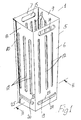
- Each bin 1 has an open topped box shaped body 5 of generally rectangular section formed by a flat plastics panel bent intermediate its ends to form a front wall 6, a rear wall 7, and end walls 8, 9.
- An L-section bonding strip 10 engages and wraps around free edges of the panel to form the body 5.
- the bonding strip 10 may be attached to the walls 7, 8 in any suitable manner such as by gluing or by sonic welding.
- a plurality of ventilation slots 12 are provided in the sidewalls 6, 7, 8, 9.
- Hand grips 14, 15 are formed by slots at an upper end of the front wall 6 and rear wall 7.
- a base 18 of the bin 1 is formed by a pair of overlapping floor plates 19, 20.
- Each floor plate 19, 20 extends through associated openings 22, 23 in opposite side walls 6, 7, 8, 9 of the body 5.
- Each floor plate 19, 20 has flanged ends 24, 25 which extend through the openings 22, 23 and engage with an outer face of the side walls to retain the floor plates 19, 20 in engagement with the side walls. It will be noted that the floor plates 19, 20 also add structural rigidity to the body 5.
- a number of drainage/ventilation openings 28 are provided in the floor plates 19, 20 to allow circulation of cooling air through the display bin 1 and drainage of moisture from the display bin 1.
- a number of the bins 1 are mounted in a refrigerated cabinet 2 as shown in Fig. 5. Products 3 for sales are then stored in each of the bins 1 which display the products 3 for sale.
- the bins 1 can be readily easily moved around the freezer cabinet as desired. Also, when restocking the refrigerated cabinet 2, a bin 1 can simply be removed and replaced with a fresh bin 1 containing the fresh stock. Any few remaining goods 3 in the old bin can be simply tipped into the new bin so that the old stock will be used first. Thus advantageously, there is no build-up of old stock at the bottom of the freezer cabinet 2 which can lead to wastage.
- FIG. 4 there is shown another display bin 40 which is largely similar to the display bin described previously and like parts are assigned the same reference numerals.
- the body 5 of the bin is more elongated and a divider panel 41 is provided for mounting within the bin 40 to subdivide the bin 40 into two separate compartments.
- the divider panel 41 engages vertical slots 12 in the sidewalls 8, 9 to support the divider panel in an upright position within the bin 40.
- a flanged lip 42 at each end of the panel 41 extends through the slots 12 to engage an outside face of the sidewalls 8, 9 to retain the panel 41 in position.
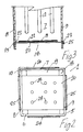
- the floor plate 50 is a generally flat rectangular plate with outwardly projecting tongues 51 along each edge for engagement within the slots 22, 23 in the side walls 6, 7, 8, 9.
- the floor plate 50 is sufficiently flexible to deform to allow engagement of the tongues 51 in the slots 22, 23.
- the floor plate 50 may be arranged to engage only two opposed slots 22, 23 in opposite side walls or in all four slots 22, 23.
- the size of the floor plate 50 is such that when the tongues 51 are snapped into engagement with the slots 22, 23 the floor plate 50 cannot be dislodged without deforming the floor plate 50.
- the display bins may be of any suitable materials of construction.
- the display bins are constructed of a plastics material.
- the plastics material is PET (polyethylene terephthalate).
- PET polyethylene terephthalate
- the term PET is to be understood to include the following: crystalisable and amorphous PET homopolymers, crystalisable and amorphous PET copolymers, crystalisable and amorphous PET compounds, crystalisable and amorphous recycled PET and other variants of amorphous and crystalisable PET.
- the floor plates may be manufactured as flat plates which are inserted through the openings in the side walls and then bent downwardly at each end to secure the floor plates in position.
- the floor plates may be formed with the flanges at each end, the floor plates being sufficiently deformable to insert the flanged ends through the openings in the side walls upon assembly of the display bin.
- one or both of the side walls may be extended around the other side wall, overlapping the side wall at the join the overlapping portions of the side walls being joined together in any suitable fashion such as welding or gluing.
- the invention provides display bins which are of relatively simple construction which are relatively easy to manufacture.
Landscapes
- Physics & Mathematics (AREA)
- Thermal Sciences (AREA)
- Freezers Or Refrigerated Showcases (AREA)
- Liquid Crystal Substances (AREA)
- Rigid Containers With Two Or More Constituent Elements (AREA)
- Vending Machines For Individual Products (AREA)
- Pharmaceuticals Containing Other Organic And Inorganic Compounds (AREA)
- Acyclic And Carbocyclic Compounds In Medicinal Compositions (AREA)
- Control Of Vending Devices And Auxiliary Devices For Vending Devices (AREA)
- Separation By Low-Temperature Treatments (AREA)
- Eye Examination Apparatus (AREA)
Abstract
Description
- This invention relates to a display system and to a display bin for use in the display system. The invention is particularly concerned with the display of chilled goods for sale in refrigerated cabinets in retail outlets.
- The invention particularly relates to a display system for a freezer display cabinet of the type described in our previously filed European Patent Application No. 97650040.5 comprising a plurality of independent display bins for mounting in the display cabinet to sub-divide the display cabinet into a number of smaller display units or compartments.
- The present invention is concerned with the manufacture of display bins for such display systems in a simple and economic manner and with constructions of the display bins which facilitate this.
- The invention is characterised in that each bin comprises a box shaped body having upstanding sidewalls and a base comprising a floor plate mounted between the sidewalls adjacent a lower end of the sidewalls, opposite sides of the floor plate engaging with opposed sidewalls to secure the floor plate between the side walls. Conveniently the body and the base are formed separately and then joined to form the bin. This simplifies the manufacturing process and enables the bin to be produced economically.
- In a particularly preferred embodiment, floor plate receiving openings are provided in the side walls, the floor plate engaging within the openings to secure the floor plate between the side walls. This construction provides for positive engagement between the floor plate and side walls for secure mounting of the floor plate on the side walls.
- In another embodiment, the floor plate has means for retaining the floor plate between the side walls in engagement with the openings.
- In a preferred embodiment, the floor plate has flanged ends for engagement through the openings with outer faces of the side walls for retaining the floor plate in engagement with the side walls. This prevents dislodgement of the floor plate from the slots.
- Ideally, a pair of overlapping floor plates are provided.
- In another embodiment, the sidewall is formed from a flat panel bent intermediate its ends, free ends of the panel being joined together. Any suitable joint may be provided. For example, a butt joint may be provided with glued edges or the edges may be sonic welded. If desired, the fee ends may be overlapped prior to gluing or sonic welding. In a further alternative, the edges may be arranged to interlock or interengage.
- In a further embodiment the free ends of the panel abut and a bonding strip is mounted across the abutting free ends, the bonding strip being secured to each of the free ends. Where the free ends join at a corner the bonding strip is of L-section. If the free ends are located between corners a flat bonding strip may be used.
- It will be appreciated that the flat panel may be prefabricated and transported whilst flat which greatly facilitates transport and then afterwards may be bent into the body shape on which the floor plates are mounted.
- In another embodiment, a divider panel is provided for mounting with the bin to subdivide the bin internally.
- Conveniently, the divider panel engages with vertical slots in opposite side walls of the bin to support the divider panel in an upright position within the bin.
- In a further embodiment the or each floor plate is mounted on the sidewalls spaced upwardly from a bottom of the side walls. This construction prevents moisture build-up in the bin which might damage goods. Drainage holes may conveniently be provided in each floor plate to ensure good drainage.
- In another aspect the invention provides a display bin for a display system of the type herein described.
- The invention will be more clearly understood by the following description of some embodiments thereof, given by way of example only, with reference to the accompanying drawings, in which:-
- Fig. 1 is a perspective view of a display bin according to the invention;
- Fig. 2 is an underneath plan view of the display bin;
- Fig. 3 is a detail sectional elevational view showing a lower portion of the bin taken along the line III-III of Fig. 1;
- Fig. 4 is a perspective view of another display bin according to the invention;
- Fig. 5 is a perspective view of a display system according to the invention comprising a number of the display bins mounted in a refrigerated cabinet; and
- Fig. 6 is a plan view of an alternative floor plate forming portion of a display bin.
-
- Referring to the drawings, there is illustrated a display bin according to the invention, indicated generally by the
reference numeral 1. A number of thedisplay bins 1 are used to form a display system according to the invention comprising a number of thedisplay bins 1 arranged within a refrigerated cabinet 2 (Fig. 5) subdividing the refrigeratedcabinet 2 into a number of smaller display compartments each containingproducts 3 for sale. - Each
bin 1 has an open topped box shapedbody 5 of generally rectangular section formed by a flat plastics panel bent intermediate its ends to form afront wall 6, a rear wall 7, andend walls section bonding strip 10 engages and wraps around free edges of the panel to form thebody 5. Thebonding strip 10 may be attached to thewalls 7, 8 in any suitable manner such as by gluing or by sonic welding. - A plurality of
ventilation slots 12 are provided in thesidewalls Hand grips 14, 15 are formed by slots at an upper end of thefront wall 6 and rear wall 7. - A
base 18 of thebin 1 is formed by a pair of overlappingfloor plates floor plate openings opposite side walls body 5. Eachfloor plate ends openings floor plates floor plates body 5. A number of drainage/ventilation openings 28 are provided in thefloor plates display bin 1 and drainage of moisture from thedisplay bin 1. - In use, a number of the
bins 1 are mounted in a refrigeratedcabinet 2 as shown in Fig. 5.Products 3 for sales are then stored in each of thebins 1 which display theproducts 3 for sale. Thebins 1 can be readily easily moved around the freezer cabinet as desired. Also, when restocking the refrigeratedcabinet 2, abin 1 can simply be removed and replaced with afresh bin 1 containing the fresh stock. Any fewremaining goods 3 in the old bin can be simply tipped into the new bin so that the old stock will be used first. Thus advantageously, there is no build-up of old stock at the bottom of thefreezer cabinet 2 which can lead to wastage. - Referring now to Fig. 4, there is shown another
display bin 40 which is largely similar to the display bin described previously and like parts are assigned the same reference numerals. In this case, thebody 5 of the bin is more elongated and a divider panel 41 is provided for mounting within thebin 40 to subdivide thebin 40 into two separate compartments. The divider panel 41 engagesvertical slots 12 in thesidewalls bin 40. Aflanged lip 42 at each end of the panel 41 extends through theslots 12 to engage an outside face of thesidewalls - Referring now to Fig. 6 there is illustrated an alternative construction of
floor plate 50. In this case thefloor plate 50 is a generally flat rectangular plate with outwardly projectingtongues 51 along each edge for engagement within theslots side walls floor plate 50 is sufficiently flexible to deform to allow engagement of thetongues 51 in theslots floor plate 50 may be arranged to engage only twoopposed slots slots floor plate 50 is such that when thetongues 51 are snapped into engagement with theslots floor plate 50 cannot be dislodged without deforming thefloor plate 50. - The display bins may be of any suitable materials of construction. Preferably the display bins are constructed of a plastics material. Most preferably the plastics material is PET (polyethylene terephthalate). The term PET is to be understood to include the following: crystalisable and amorphous PET homopolymers, crystalisable and amorphous PET copolymers, crystalisable and amorphous PET compounds, crystalisable and amorphous recycled PET and other variants of amorphous and crystalisable PET.
- The floor plates may be manufactured as flat plates which are inserted through the openings in the side walls and then bent downwardly at each end to secure the floor plates in position. Alternatively the floor plates may be formed with the flanges at each end, the floor plates being sufficiently deformable to insert the flanged ends through the openings in the side walls upon assembly of the display bin.
- It will also be noted that instead of using the bonding strip to join the free ends of the body as described above one or both of the side walls may be extended around the other side wall, overlapping the side wall at the join the overlapping portions of the side walls being joined together in any suitable fashion such as welding or gluing.
- It will be appreciated that the invention provides display bins which are of relatively simple construction which are relatively easy to manufacture.
- The invention is not limited to the embodiments hereinbefore described which may be varied in both construction and detail.
Claims (10)
- A display system for a display cabinet, the display system comprising a plurality of independent display bins for mounting in the display cabinet to sub-divide the display cabinet into a number of smaller display units or compartments, characterised in that each bin comprises a box shaped body having upstanding sidewalls and a base comprising a floor plate mounted between the sidewalls adjacent a lower end of the sidewalls, opposite sides of the floor plate engaging with opposed side walls to secure the floor plate between the side walls.
- A system as claimed in claim 1, wherein floor plate receiving openings are provided in the side walls, the floor plate engaging within the openings to secure the floor plate between the side walls.
- A system as claimed in claim 2, wherein the floor plate has means for retaining the floor plate between the side walls in engagement with the openings.
- A system as claimed in claim 3, wherein the floor plate has flanged ends for engagement through the openings with outer faces of the side walls for retaining the floor plate in engagement with the side walls.
- A system as claimed in any preceding claim, wherein a pair of overlapping floor plates are provided, each engaging a pair of opposed side walls of the bin body.
- A system as claimed in any preceding claim, wherein the bin body is formed from a flat panel bent intermediate its ends, free ends of the panel being joined together.
- A system as claimed in any preceding claim, wherein a divider panel is provided for mounting within the bin to sub-divide the bin internally.
- A system as claimed in claim 7, wherein the divider panel engages with vertical slots in opposite side walls of the bin to support the divider panel in an upright position within the bin.
- A system as claimed in any preceding claim, wherein the or each floor plate is mounted on the sidewalls spaced upwardly from a bottom of the side walls.
- A display bin for a display cabinet display system as claimed in any preceding claim, the display bin comprising a box shaped body having upstanding side walls and a base comprising a floor plate mounted between the side walls adjacent a lower end of the side walls, opposite sides of the floor plate engaging with opposed side walls to secure the floor plate between the side walls.
Applications Claiming Priority (2)
| Application Number | Priority Date | Filing Date | Title |
|---|---|---|---|
| IE970844 | 1997-11-28 | ||
| IE970844 | 1997-11-28 |
Publications (3)
| Publication Number | Publication Date |
|---|---|
| EP0919164A2 true EP0919164A2 (en) | 1999-06-02 |
| EP0919164A3 EP0919164A3 (en) | 2000-03-15 |
| EP0919164B1 EP0919164B1 (en) | 2004-08-04 |
Family
ID=11041647
Family Applications (1)
| Application Number | Title | Priority Date | Filing Date |
|---|---|---|---|
| EP98650079A Expired - Lifetime EP0919164B1 (en) | 1997-11-28 | 1998-11-30 | A display system |
Country Status (7)
| Country | Link |
|---|---|
| EP (1) | EP0919164B1 (en) |
| AT (1) | ATE272345T1 (en) |
| DE (1) | DE69825394T2 (en) |
| DK (1) | DK0919164T3 (en) |
| ES (1) | ES2230663T3 (en) |
| IE (1) | IE980993A1 (en) |
| PT (1) | PT919164E (en) |
Cited By (3)
| Publication number | Priority date | Publication date | Assignee | Title |
|---|---|---|---|---|
| EP1174059A1 (en) * | 2000-07-21 | 2002-01-23 | Warner-Lambert Company | Sales cabinet with a built-in product display |
| EP1177751A1 (en) * | 2000-07-21 | 2002-02-06 | Warner-Lambert Company | Sales cabinet with a built-in product display |
| CN107232877A (en) * | 2016-03-29 | 2017-10-10 | 上海聚特展示用品有限公司 | A kind of Combined corner display box |
Citations (6)
| Publication number | Priority date | Publication date | Assignee | Title |
|---|---|---|---|---|
| US1701019A (en) * | 1927-03-24 | 1929-02-05 | Leslie T Summers | Meat cooling and dispensing case |
| FR2064531A5 (en) * | 1969-09-22 | 1971-07-23 | Grosfillex Sarl | |
| FR2248980A2 (en) * | 1973-10-29 | 1975-05-23 | Epex | Box and cover for wet or frozen products - corners have different height double layers supporting the cover |
| US4593816A (en) * | 1985-09-03 | 1986-06-10 | Langenbeck Keith A | Container for storing and transporting letter mail and other flat articles |
| US5268149A (en) * | 1992-03-09 | 1993-12-07 | Nabil Arafat | Universal transportation tray for laboratory volumetric equipment |
| WO1994022351A1 (en) * | 1993-04-02 | 1994-10-13 | L & P Property Management Company | Merchandising display system including gravity feed tray |
-
1998
- 1998-11-30 PT PT98650079T patent/PT919164E/en unknown
- 1998-11-30 DK DK98650079T patent/DK0919164T3/en active
- 1998-11-30 AT AT98650079T patent/ATE272345T1/en not_active IP Right Cessation
- 1998-11-30 IE IE19980993A patent/IE980993A1/en not_active IP Right Cessation
- 1998-11-30 ES ES98650079T patent/ES2230663T3/en not_active Expired - Lifetime
- 1998-11-30 DE DE69825394T patent/DE69825394T2/en not_active Expired - Fee Related
- 1998-11-30 EP EP98650079A patent/EP0919164B1/en not_active Expired - Lifetime
Patent Citations (6)
| Publication number | Priority date | Publication date | Assignee | Title |
|---|---|---|---|---|
| US1701019A (en) * | 1927-03-24 | 1929-02-05 | Leslie T Summers | Meat cooling and dispensing case |
| FR2064531A5 (en) * | 1969-09-22 | 1971-07-23 | Grosfillex Sarl | |
| FR2248980A2 (en) * | 1973-10-29 | 1975-05-23 | Epex | Box and cover for wet or frozen products - corners have different height double layers supporting the cover |
| US4593816A (en) * | 1985-09-03 | 1986-06-10 | Langenbeck Keith A | Container for storing and transporting letter mail and other flat articles |
| US5268149A (en) * | 1992-03-09 | 1993-12-07 | Nabil Arafat | Universal transportation tray for laboratory volumetric equipment |
| WO1994022351A1 (en) * | 1993-04-02 | 1994-10-13 | L & P Property Management Company | Merchandising display system including gravity feed tray |
Cited By (3)
| Publication number | Priority date | Publication date | Assignee | Title |
|---|---|---|---|---|
| EP1174059A1 (en) * | 2000-07-21 | 2002-01-23 | Warner-Lambert Company | Sales cabinet with a built-in product display |
| EP1177751A1 (en) * | 2000-07-21 | 2002-02-06 | Warner-Lambert Company | Sales cabinet with a built-in product display |
| CN107232877A (en) * | 2016-03-29 | 2017-10-10 | 上海聚特展示用品有限公司 | A kind of Combined corner display box |
Also Published As
| Publication number | Publication date |
|---|---|
| DK0919164T3 (en) | 2005-01-24 |
| EP0919164B1 (en) | 2004-08-04 |
| ES2230663T3 (en) | 2005-05-01 |
| IE980993A1 (en) | 2000-02-23 |
| ATE272345T1 (en) | 2004-08-15 |
| EP0919164A3 (en) | 2000-03-15 |
| PT919164E (en) | 2004-12-31 |
| DE69825394D1 (en) | 2004-09-09 |
| DE69825394T2 (en) | 2005-08-11 |
Similar Documents
| Publication | Publication Date | Title |
|---|---|---|
| US4015886A (en) | Storage bins | |
| US4484661A (en) | Drip pan for vehicles | |
| EP0928147B1 (en) | Display rack with channel front member | |
| US6253948B1 (en) | Nestable container with expendable closure panel covering access opening in container wall | |
| US20180009101A1 (en) | Totes or bins and systems & methods for storing products | |
| US5397022A (en) | Box-shaped containers of plastics material | |
| CA2281232C (en) | Pre-packed product shipment and display device with spring-biased restocking feed arrangement | |
| CA2590385A1 (en) | Shipping and display tray | |
| US20030164665A1 (en) | Drawer partitioning system and fastening arrangement therefor | |
| US5598932A (en) | Rack for storage of frozen pizzas | |
| EP0919164B1 (en) | A display system | |
| GB2180821A (en) | Trays for use in cooperation with one another | |
| US3908566A (en) | Modular shelving system for food service storage | |
| US4473155A (en) | Stacking and nesting bin | |
| US6705484B2 (en) | Plastic transport container with reinforced floor | |
| US3578235A (en) | Tray for carmels | |
| US6557718B1 (en) | Superimposable and interpenetrable plastics box | |
| WO2018009519A1 (en) | Totes or bins and systems & methods for storing products | |
| US5457859A (en) | Modular clip and assembly using same | |
| US4121710A (en) | Display bin | |
| EP0839482A2 (en) | A display system | |
| NL9002055A (en) | Goods display container arrangement - has identical stackable crates, with removable partitions and includes vertical guide supports | |
| JPH0628426Y2 (en) | Collection container | |
| GB2368337A (en) | Nestable and stackable crates | |
| AU676192B2 (en) | Goods crate |
Legal Events
| Date | Code | Title | Description |
|---|---|---|---|
| PUAI | Public reference made under article 153(3) epc to a published international application that has entered the european phase |
Free format text: ORIGINAL CODE: 0009012 |
|
| AK | Designated contracting states |
Kind code of ref document: A2 Designated state(s): AT BE CH CY DE DK ES FI FR GB GR IE IT LI LU MC NL PT SE |
|
| AX | Request for extension of the european patent |
Free format text: AL;LT;LV;MK;RO;SI |
|
| PUAL | Search report despatched |
Free format text: ORIGINAL CODE: 0009013 |
|
| AK | Designated contracting states |
Kind code of ref document: A3 Designated state(s): AT BE CH CY DE DK ES FI FR GB GR IE IT LI LU MC NL PT SE |
|
| AX | Request for extension of the european patent |
Free format text: AL;LT;LV;MK;RO;SI |
|
| 17P | Request for examination filed |
Effective date: 20000908 |
|
| AKX | Designation fees paid |
Free format text: AT BE CH CY DE DK ES FI FR GB GR IE IT LI LU MC NL PT SE |
|
| 17Q | First examination report despatched |
Effective date: 20030217 |
|
| GRAP | Despatch of communication of intention to grant a patent |
Free format text: ORIGINAL CODE: EPIDOSNIGR1 |
|
| GRAS | Grant fee paid |
Free format text: ORIGINAL CODE: EPIDOSNIGR3 |
|
| GRAA | (expected) grant |
Free format text: ORIGINAL CODE: 0009210 |
|
| AK | Designated contracting states |
Kind code of ref document: B1 Designated state(s): AT BE CH CY DE DK ES FI FR GB GR IE IT LI LU MC NL PT SE |
|
| PG25 | Lapsed in a contracting state [announced via postgrant information from national office to epo] |
Ref country code: CY Free format text: LAPSE BECAUSE OF FAILURE TO SUBMIT A TRANSLATION OF THE DESCRIPTION OR TO PAY THE FEE WITHIN THE PRESCRIBED TIME-LIMIT Effective date: 20040804 Ref country code: BE Free format text: LAPSE BECAUSE OF FAILURE TO SUBMIT A TRANSLATION OF THE DESCRIPTION OR TO PAY THE FEE WITHIN THE PRESCRIBED TIME-LIMIT Effective date: 20040804 |
|
| REG | Reference to a national code |
Ref country code: GB Ref legal event code: FG4D |
|
| REG | Reference to a national code |
Ref country code: CH Ref legal event code: EP |
|
| REG | Reference to a national code |
Ref country code: IE Ref legal event code: FG4D |
|
| REF | Corresponds to: |
Ref document number: 69825394 Country of ref document: DE Date of ref document: 20040909 Kind code of ref document: P |
|
| PGFP | Annual fee paid to national office [announced via postgrant information from national office to epo] |
Ref country code: SE Payment date: 20041103 Year of fee payment: 7 |
|
| PGFP | Annual fee paid to national office [announced via postgrant information from national office to epo] |
Ref country code: FI Payment date: 20041105 Year of fee payment: 7 |
|
| PGFP | Annual fee paid to national office [announced via postgrant information from national office to epo] |
Ref country code: IE Payment date: 20041128 Year of fee payment: 7 |
|
| PGFP | Annual fee paid to national office [announced via postgrant information from national office to epo] |
Ref country code: PT Payment date: 20041129 Year of fee payment: 7 |
|
| PG25 | Lapsed in a contracting state [announced via postgrant information from national office to epo] |
Ref country code: MC Free format text: LAPSE BECAUSE OF NON-PAYMENT OF DUE FEES Effective date: 20041130 Ref country code: LU Free format text: LAPSE BECAUSE OF NON-PAYMENT OF DUE FEES Effective date: 20041130 |
|
| PGFP | Annual fee paid to national office [announced via postgrant information from national office to epo] |
Ref country code: FR Payment date: 20041130 Year of fee payment: 7 Ref country code: ES Payment date: 20041130 Year of fee payment: 7 Ref country code: DK Payment date: 20041130 Year of fee payment: 7 Ref country code: NL Payment date: 20041130 Year of fee payment: 7 Ref country code: GR Payment date: 20041130 Year of fee payment: 7 Ref country code: GB Payment date: 20041130 Year of fee payment: 7 Ref country code: AT Payment date: 20041130 Year of fee payment: 7 |
|
| REG | Reference to a national code |
Ref country code: SE Ref legal event code: TRGR |
|
| PGFP | Annual fee paid to national office [announced via postgrant information from national office to epo] |
Ref country code: CH Payment date: 20041201 Year of fee payment: 7 |
|
| REG | Reference to a national code |
Ref country code: GR Ref legal event code: EP Ref document number: 20040403778 Country of ref document: GR |
|
| REG | Reference to a national code |
Ref country code: PT Ref legal event code: SC4A Free format text: AVAILABILITY OF NATIONAL TRANSLATION Effective date: 20041104 |
|
| REG | Reference to a national code |
Ref country code: DK Ref legal event code: T3 |
|
| PGFP | Annual fee paid to national office [announced via postgrant information from national office to epo] |
Ref country code: DE Payment date: 20050128 Year of fee payment: 7 |
|
| REG | Reference to a national code |
Ref country code: ES Ref legal event code: FG2A Ref document number: 2230663 Country of ref document: ES Kind code of ref document: T3 |
|
| PLBE | No opposition filed within time limit |
Free format text: ORIGINAL CODE: 0009261 |
|
| STAA | Information on the status of an ep patent application or granted ep patent |
Free format text: STATUS: NO OPPOSITION FILED WITHIN TIME LIMIT |
|
| ET | Fr: translation filed | ||
| 26N | No opposition filed |
Effective date: 20050506 |
|
| PG25 | Lapsed in a contracting state [announced via postgrant information from national office to epo] |
Ref country code: LI Free format text: LAPSE BECAUSE OF NON-PAYMENT OF DUE FEES Effective date: 20051130 Ref country code: IT Free format text: LAPSE BECAUSE OF NON-PAYMENT OF DUE FEES Effective date: 20051130 Ref country code: IE Free format text: LAPSE BECAUSE OF NON-PAYMENT OF DUE FEES Effective date: 20051130 Ref country code: GB Free format text: LAPSE BECAUSE OF NON-PAYMENT OF DUE FEES Effective date: 20051130 Ref country code: FI Free format text: LAPSE BECAUSE OF NON-PAYMENT OF DUE FEES Effective date: 20051130 Ref country code: DK Free format text: LAPSE BECAUSE OF NON-PAYMENT OF DUE FEES Effective date: 20051130 Ref country code: AT Free format text: LAPSE BECAUSE OF NON-PAYMENT OF DUE FEES Effective date: 20051130 |
|
| PG25 | Lapsed in a contracting state [announced via postgrant information from national office to epo] |
Ref country code: SE Free format text: LAPSE BECAUSE OF NON-PAYMENT OF DUE FEES Effective date: 20051201 Ref country code: ES Free format text: LAPSE BECAUSE OF NON-PAYMENT OF DUE FEES Effective date: 20051201 |
|
| REG | Reference to a national code |
Ref country code: CH Ref legal event code: NV Representative=s name: ISLER & PEDRAZZINI AG |
|
| PG25 | Lapsed in a contracting state [announced via postgrant information from national office to epo] |
Ref country code: PT Free format text: LAPSE BECAUSE OF NON-PAYMENT OF DUE FEES Effective date: 20060531 |
|
| PG25 | Lapsed in a contracting state [announced via postgrant information from national office to epo] |
Ref country code: NL Free format text: LAPSE BECAUSE OF NON-PAYMENT OF DUE FEES Effective date: 20060601 Ref country code: DE Free format text: LAPSE BECAUSE OF NON-PAYMENT OF DUE FEES Effective date: 20060601 |
|
| REG | Reference to a national code |
Ref country code: DK Ref legal event code: EBP |
|
| REG | Reference to a national code |
Ref country code: CH Ref legal event code: PL |
|
| GBPC | Gb: european patent ceased through non-payment of renewal fee |
Effective date: 20051130 |
|
| PG25 | Lapsed in a contracting state [announced via postgrant information from national office to epo] |
Ref country code: FR Free format text: LAPSE BECAUSE OF NON-PAYMENT OF DUE FEES Effective date: 20060731 |
|
| REG | Reference to a national code |
Ref country code: PT Ref legal event code: MM4A Effective date: 20060531 |
|
| NLV4 | Nl: lapsed or anulled due to non-payment of the annual fee |
Effective date: 20060601 |
|
| EUG | Se: european patent has lapsed | ||
| REG | Reference to a national code |
Ref country code: IE Ref legal event code: MM4A |
|
| REG | Reference to a national code |
Ref country code: FR Ref legal event code: ST Effective date: 20060731 |
|
| REG | Reference to a national code |
Ref country code: ES Ref legal event code: FD2A Effective date: 20051201 |
|
| PG25 | Lapsed in a contracting state [announced via postgrant information from national office to epo] |
Ref country code: GR Free format text: LAPSE BECAUSE OF NON-PAYMENT OF DUE FEES Effective date: 20040804 |