EP0918917B1 - Verfahren zum verrohren eines bohrlochs - Google Patents
Verfahren zum verrohren eines bohrlochs Download PDFInfo
- Publication number
- EP0918917B1 EP0918917B1 EP97934670A EP97934670A EP0918917B1 EP 0918917 B1 EP0918917 B1 EP 0918917B1 EP 97934670 A EP97934670 A EP 97934670A EP 97934670 A EP97934670 A EP 97934670A EP 0918917 B1 EP0918917 B1 EP 0918917B1
- Authority
- EP
- European Patent Office
- Prior art keywords
- casing
- tubing
- string
- tool
- end portion
- Prior art date
- Legal status (The legal status is an assumption and is not a legal conclusion. Google has not performed a legal analysis and makes no representation as to the accuracy of the status listed.)
- Expired - Lifetime
Links
- 238000000034 method Methods 0.000 title claims description 14
- 239000004568 cement Substances 0.000 claims description 34
- 239000012530 fluid Substances 0.000 claims description 28
- 239000002184 metal Substances 0.000 claims description 22
- 239000002002 slurry Substances 0.000 claims description 14
- 238000005086 pumping Methods 0.000 claims description 11
- 238000005452 bending Methods 0.000 claims description 5
- 238000007789 sealing Methods 0.000 claims description 5
- 230000009977 dual effect Effects 0.000 claims description 4
- 239000000919 ceramic Substances 0.000 claims description 3
- 238000005096 rolling process Methods 0.000 claims description 3
- 238000004804 winding Methods 0.000 claims 3
- 238000004891 communication Methods 0.000 claims 2
- 238000005242 forging Methods 0.000 description 12
- 238000005553 drilling Methods 0.000 description 10
- 238000009434 installation Methods 0.000 description 6
- 230000007246 mechanism Effects 0.000 description 6
- 238000004519 manufacturing process Methods 0.000 description 4
- 229910000831 Steel Inorganic materials 0.000 description 3
- 239000004020 conductor Substances 0.000 description 3
- 239000010959 steel Substances 0.000 description 3
- 238000013459 approach Methods 0.000 description 2
- 230000015572 biosynthetic process Effects 0.000 description 2
- 239000002131 composite material Substances 0.000 description 2
- 230000006835 compression Effects 0.000 description 2
- 238000007906 compression Methods 0.000 description 2
- 230000008878 coupling Effects 0.000 description 2
- 238000010168 coupling process Methods 0.000 description 2
- 238000005859 coupling reaction Methods 0.000 description 2
- 238000005520 cutting process Methods 0.000 description 2
- 238000013461 design Methods 0.000 description 2
- 238000011065 in-situ storage Methods 0.000 description 2
- 239000010410 layer Substances 0.000 description 2
- 238000012856 packing Methods 0.000 description 2
- 239000003381 stabilizer Substances 0.000 description 2
- 238000006243 chemical reaction Methods 0.000 description 1
- 239000011248 coating agent Substances 0.000 description 1
- 238000000576 coating method Methods 0.000 description 1
- 230000007423 decrease Effects 0.000 description 1
- 239000002355 dual-layer Substances 0.000 description 1
- 230000002708 enhancing effect Effects 0.000 description 1
- 238000011010 flushing procedure Methods 0.000 description 1
- 230000002706 hydrostatic effect Effects 0.000 description 1
- 239000000463 material Substances 0.000 description 1
- 230000013011 mating Effects 0.000 description 1
- 238000004381 surface treatment Methods 0.000 description 1
- 238000012360 testing method Methods 0.000 description 1
- 238000003466 welding Methods 0.000 description 1
Images




Classifications
-
- E—FIXED CONSTRUCTIONS
- E21—EARTH OR ROCK DRILLING; MINING
- E21B—EARTH OR ROCK DRILLING; OBTAINING OIL, GAS, WATER, SOLUBLE OR MELTABLE MATERIALS OR A SLURRY OF MINERALS FROM WELLS
- E21B19/00—Handling rods, casings, tubes or the like outside the borehole, e.g. in the derrick; Apparatus for feeding the rods or cables
- E21B19/22—Handling reeled pipe or rod units, e.g. flexible drilling pipes
-
- E—FIXED CONSTRUCTIONS
- E21—EARTH OR ROCK DRILLING; MINING
- E21B—EARTH OR ROCK DRILLING; OBTAINING OIL, GAS, WATER, SOLUBLE OR MELTABLE MATERIALS OR A SLURRY OF MINERALS FROM WELLS
- E21B43/00—Methods or apparatus for obtaining oil, gas, water, soluble or meltable materials or a slurry of minerals from wells
- E21B43/02—Subsoil filtering
- E21B43/10—Setting of casings, screens, liners or the like in wells
- E21B43/103—Setting of casings, screens, liners or the like in wells of expandable casings, screens, liners, or the like
- E21B43/105—Expanding tools specially adapted therefor
Definitions
- This invention relates in general to installing well casing in oil and gas wells and in particular to a method involving fabricating and collapsing casing, running the collapsed casing into the well and opening the casing into a cylindrical configuration.
- Oil and gas wells are typically drilled by installing a conductor pipe to first depth, then drilling the well to a second depth.
- a string of casing is made up by coupling together sections of pipe, each being about forty feet long and lowering it inside the conductor pipe in a nested arrangement. Cement is then pumped down the casing which flows back up the annulus between the casing and the open borehole. Drilling is resumed to a third depth and the process is repeated with another smaller diameter nested casing. An even smaller diameter string of casing may be installed at a fourth depth.
- casings serve to support the borehole wall and to prevent undesired outflow of drilling fluid into the formation or inflow of fluid from the formation into the borehole from strata other than the target production strata.
- the nested arrangement requires a relative large borehole at the upper part of the wellbore due to the thickness of casing couplings and also due to the minimum clearance necessary between casing to displace cement in the annulus space.
- Liners are employed in some wells.
- a liner is similar to a casing, however, rather than extending completely to the surface wellhead, the upper end of the liner is suspended on the lower end of the previous string. Liners still must be run by making-up pipe sections together and are employed usually to extend in limited lengths from only the smallest diameter full length casing installed.
- Coiled tubing units permit one to rapidly run a continuous metallic tubing into a well.
- the tubing is plastically coiled on large reels.
- a pushing mechanism straightens up the tubing and lowers it into the well as it is uncoiled from the reel.
- Coiled tubing is used to circulate fluids into wells for various purposes. However, it is seldom used to serve as casing due to its small diameter.
- Coiled tubing is smaller in diameter than typical casing, which have usually a minimum diameter of five inches. It would require a large reel to be able to coil several thousand feet of metallic casing of five inches in diameter or larger.
- US 5,291,956 illustrates such coiled tubing and deployment unit used in drilling.
- US 5,337,823 discloses an approach to solve the conflicting requirement of large diameter casing (5" and above) and continuous reeled length by using a soft composite material pipe hardened in situ after deployment in the well. Shortcoming of this approach is the lack of opening tool to prevent pocket of fluid to be trapped outside the casing while being inflated and a lack of cost effectiveness due to the cost of composite material compared to steel.
- WO 9622452 discloses a conical expanding mandrel used to increase the diameter in situs of steel slotted pervious casing by vertical pull of the mandrel or by radial hydraulic expansion. Mechanical pull of a mandrel inside a downhole casing is facing reaction problem and the section by section hydraulic expansion is not really practical for extended casing length.
- a metal strip plate is formed in a generally tubular configuration, and welded longitudinally with at least one string of continuous tubing inserted during the manufacturing process.
- circular pipe sections about forty feet long are welded together and strings of tubing are threaded inside.
- the casing is then collapsed with the tubing located therein and wound on a small reel due to its small height by comparison to its nominal diameter.
- the upper and lower end portions of the casings are generally formed in a somewhat cylindrical configuration.
- An opening tool is located in the lower end cylindrical portion. The opening tool has a piston and a conical forming head located above the piston. A pressure chamber is created below the piston in the lower end portion of the casing.
- the casing is deployed from the reel and folded in a horseshoe shape prior to entering the well.
- a fluid is pumped down the tubing into the pressure chamber to open the casing into a cylindrical shape.
- the fluid pressure acts against the piston to push the opening tool upward. This causes the head of the opening tool to form the casing from the collapsed/folded configuration into a cylindrical configuration.
- the forming tool and the tubing are then pulled from the casing.
- two strings of tubing are installed in the casing while it is being manufactured.
- One of the strings of tubing serves to pump a cement slurry down through a cement shoe located at the lower end of the casing. The cement flows back up the annulus surrounding the casing to cement the casing in place. Then fluid is pumped down the other string of tubing to open the casing.
- a forging tool is used to expand the upper end cylindrical portion of the casing into a metal to metal sealing engagement with the lower end of the previously cased section of the well.
- this involves releasing the running tool from the upper end of the casing after the collapsed portion of the casing has been expanded, then lowering the forging tool located above the running tool into the casing. Fluid is then pumped down to radially forge the upper end of the casing into engagement with the lower end of the previous one.
- the opening tool includes a forming head with a conical body with flutes. Balls roll along the flutes in rolling engagement with the casing wall as it is being open to a cylindrical configuration. The balls force the opening of the casing as they roll along the flutes. The balls roll from the flutes into a lower ball passage, an axial passage, into an upper passage, and back into the flutes in a continuous cycle.
- the forming head comprises a conical body with thin dual conical segments to increase the forming head diameter
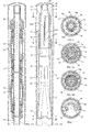
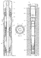
- the well illustrated has a cased section 11 which has already been cemented in place and an open hole section 13 which extends below cased section 11 to the target depth.
- a continuous string of casing 15 according to the invention is shown in place in the well with a lower end portion 15a at the lower end of the well open hole section 13.
- Casing 15 has an intermediate portion 15b that extends from the lower end portion upward, typically several thousand feet, to an upper end portion 15c.
- Upper end portion 15c overlaps the lower portion of cased section 11.
- Casing lower and upper end portions 15a, 15c each are somewhat cylindrical with axially extending corrugations 17 as shown in Figure 5.
- Corrugations 17 are straight axially extending channels on both the inner and outer diameters of casing, providing inward protruding valleys 17a alternating with outward protruding peaks 17b.
- Intermediate portion 15b, shown in Figure 4 is collapsed and folded, having a bight 18 that curves inward and touches the opposite side, which is generally arcuate when lowered into the wellbore.
- a cement shoe 19 is located at the lower end of casing lower end portion 15a.
- Cement shoe 19 provides a end cap for casing 15 and is made of drillable material with a cementing port 20 extending axially through it.
- a metal stinger 21 engages sealingly into the upper portion of cementing port 20.
- Stinger 21 is a tubular member having a conduit 23 for pumping down a cement slurry through cementing port 20 which flow back up the annulus space surrounding the casing 15, as indicated by the arrows.
- Stinger 21 has also some flow ports 25 which are isolated from conduit 23 and lead to the exterior of stinger 21.
- a cement slurry tubing 27 extends continuously through casing 15, and has its lower end coupled to stinger 21 for connecting with conduit 23.
- a fill-up tubing 29 extends continuously through casing 15 and has its lower end coupled to stinger 21 for delivering fluid to ports 25.
- Tubing strings 27, 29 are, conventional metal coiled tubing strings of about one inch in diameter.
- Opening tool 31 is housed in casing lower end portion 15a, shown in Figure 1C, above stinger 21. Opening tool 31 includes on its lower end a piston 33.
- Piston 33 is an elastomeric cup sliding seal, which has straight axially extending grooves on its exterior for meshing with the corrugations 17 of casing lower end portion 15a. Piston 33 has a packing element 33a to seal around tubing strings 27, 29.
- a pressure chamber 35 is located in the space surrounding stinger 21 above cement shoe 19 and below piston 33. In the running-in position, as shown in Figure 1D, pressure chamber 35 is at its minimum volume.
- a cylindrical metal piston head 37 extends upward from piston 33. Piston head 37 is engaging a sleeve 48 which a smaller outer diameter than the inner diameter of casing lower end portion 15a at valleys 17a.
- Opening tool 31 has a tapered or conical forming head 39 that tapers from a smaller diameter upper end to a larger diameter at lower end.
- Head 39 has vertical flutes 41 which align with valleys 17a, as shown in Figure 5.
- a plurality of balls 43 roll down flutes 41 of head 39.
- Balls 43 are movable through two axial passages 45, a plurality of lower lateral passages 47, and a plurality of upper lateral passages 49.
- Piston head 37 initially is in a lower position within a sleeve 48 of head 39, providing a chamber for a number of balls 43 as shown in Figure 1C.
- opening tool 31 has a cylindrical top end 51 which has an outer diameter equal to the minimum inner diameter of casing lower end portion 15a, which is measured at valleys 17a. Balls 43 will engage valleys 17a when contained in flutes 41 and bend the casing wall to line up with expanded peaks 17b. While at the upper end of flutes 41, the diameter from one ball 43 to an opposite ball 43 is substantially equal to the diameter between valleys 17a. When balls 43 are at the lower ends of flutes 41, as shown in Figure 8A, the outer diameter of forming tool 31 measured from one ball 43 to an opposite ball 43 at the lower ends of flute 41 is greater than the minimum inner diameter of casing lower end portion 15c. Consequently, balls 43 push valleys 17a outward to open, in a smooth circular configuration, the upper end of casing lower portion 15a as opening tool 31 moves upward.
- the intermediate portion 15b is opened from its folded configuration ahead of the opening tool 31, and the contact between the inner wall and the opening tool 31 is made only by the balls 43 rolling on flutes 41 of the conical forming head 39.
- a running tool 55 is located at the top of casing upper end portion 15c.
- Running tool 55 is a tubular member which has an outer sleeve 56.
- the exterior of outer sleeve 56 has vertical grooves 58 between vertical bands 58a.
- Outer sleeve has a set of threads on bands 58a which engages a mating set of threads 57 formed on valleys 17a in the upper inside end of casing upper end portion 15c. Because of corrugations 17 and grooves 58, threads 57 will be discontinuous and located only on the valleys 17a.
- Outer sleeve 56 is supported by an inner body 59, which has a smooth cylindrical exterior.
- Outer sleeve 56 has a J-pin 61 that protrudes inwardly into an elongated U-shaped J-slot 63 formed in outer body 59.
- J-slot 63 has a first leg 63a and a parallel second leg 63a joined at the bottom.
- J-pin 61 will be at the upper end of the first leg 63a and maintained in this position by the weight of the casing 15 hanging on the running string connected to the inner body 59.
- casing intermediate portion 15b After casing intermediate portion 15b has been opened, the weight of the casing 15 is supported by the numerous contacts with the inner wall of the borehole.
- Running tool 55 has a main supply passage 64 connected to the passage in the lower part of packer string 69 which extends into inner body 59.
- a cement slurry passage 65 (Fig. 3A) connected to tubing string 27 is located in running tool 55 and can be connected to the lower end of main supply passage 64.
- a fill-up passage 67 connected to tubing string 29 can be connected to the lower end of main supply passage 64.
- Inner body 59 of running tool 55 is connected to the packer string 69 by threads.
- the upper part of packer string 69 features a centralizer 70.
- Two or more forging packers 71 are mounted on the packer string 69 between centralizer 70 and inner body 59.
- Forging packers 71 when supplied with high internal pressure from a down hole pressure multiplicator (not shown), will inflate and radially expand to plastically forge the upper end of casing upper end portion 15c, as shown in Figure 12.
- Hydraulic passages 73 extending through packer string 69, can be connected via pressure multiplicator to lower end of main supply passage 64 within running tool inner body 59.
- Paker string 69 is connected at centralizer 70 to a the running string 72 which extends to the surface.
- running string 72 is another string of coiled tubing approximately two inches in diameter.
- Packers 71 have external axial grooves 74 which will align with valleys 17a of casing upper end portion 15c when packers 71 are lowered into upper end portion 15c with the centralizer 70 landed on top of the casing 15c as shown in Figure 12.
- valves 75, 77 and 79 are mounted in running tool inner body 59 (Fig. 1B).
- Valve 75 is in slurry passage 65 and opens and closes flow to tubing 27.
- Valve 77 is in opening fluid passage 67 for opening and closing flow from main supply passage 64 to tubing 29.
- Valve 79 is in pressure passage 73 for opening and closing pressure fluid from main supply passage 64 to forging packers 71 (Fig. 1A).
- Electrical valve control wires (not shown) extend through coiled running string 72 to the surface to a control panel.
- a small accumulator (not shown) supplies hydraulic fluid to valves 73, 77, 79 to open and close them when electrically actuated.
- Pumps 80 on the surface which could be either cement or mud pumps are used for delivering pressure fluid down main supply passage 64.
- casing 15 is fabricated by drawing a first metal strip 81 from a reel and bending two edges down around two laterally spaced apart, parallel continuous strings of coiled tubing 27, 29. As shown in Figure 16, the edges are bent over and welded at seam 82. The upper side is bent into a concave shape touching seam 82, while the lower side is flat. Then, a second strip 83 is drawn from a reel and bent to have upturned edges. As shown in Figure 17, second strip 83 is then bent by rollers around first strip 81 while first strip 81 is in the configuration shown in Figure 16. Rollers then bend the upper side of strip 83 into a concave shape as shown in Figure 20. Casing 15 thus is double-walled and has a flat side 85 that extends between parallel tubing strings 27, 29, generally tangent to outer diameter portions of tubing strings 27, 29.
- casing 15 reduces the amount of strain that would otherwise occur during opening plastic deformation with a single wall casing having the same total thickness.
- Three or more wall casings might be desirable in certain cases.
- Casing made of multiple wall needs good friction between the wall to resist external pressure.
- Known friction enhancing techniques such as surface stamping, surface treatment or coating are desirable to offer adequate external pressure capability when open.
- the circumference of the external wall can be made slightly smaller than the previous one to offer adequate fretting of the wall when casing is open.
- Casing 15 will be coiled on a reel 87 (Fig. 19) while in the configuration shown in Figure 20.
- Reel 87 is a large member capable of holding up to 5000 feet of casing 15 which has a 5-1/2 inch external diameter when expanded to a cylindrical configuration.
- Figure 18 illustrates corrugations 17 which are formed on both the upper and lower end portions 15c, 15a (Figs 1B, 1D) by a roller corrugating operation.
- the upper and lower end portions 15c, 15a remain generally cylindrical, although corrugated.
- the straight upper and lower end portions 15c, 15a are only a few feet in length and are not wound on reel 87 during transportation from the manufacturing plant to the well site.
- casing intermediate portion 15b When deploying casing 15 from reel 87, casing intermediate portion 15b will first pass through a set of bending rollers 89 as shown schematically in Figure 19. Folding rollers 89 will form casing 15 from the collapsed flattened configuration of Figure 20 to the folded collapsed configuration shown in Figure 21. This creates bight 18, and positions tubing strings 27, 29 closer toward each other.
- the maximum width of casing intermediate portion 15b in the rounded collapsed configuration of Figure 21, is less than the inner diameter of cased section 11 (Fig. 1A).
- the maximum width of casing intermediate portion 15b while in the collapsed flattened configuration of Figure 20 is greater than the inner diameter of cased section 11.
- a gripping and pushing mechanism 91 is employed.
- the folding pushing mechanism 91 is constructed generally as in a conventional coiled tubing pushing mechanisms. It grips casing 15 without deformation, pulls it from reel 87, and pushes it downward into the well.
- the horseshoe shape of Figure 21 resists the compression applied by gripping and pushing mechanism 91 while being pushed into the well.
- casing 15 will be uncoiled from reel 87 and pushed by mechanism 91 into the well until cement shoe 19 is close to the bottom of open hole section 13.
- the length of casing 15 will be previously selected so that the upper end of portion 15c extends into cased section 11 (Fig. 1B), overlapping it over a substantial length.
- Valves 77, 79 are closed and valve 75 (Fig. 22) is open and cement pump 80 pumps a cement slurry 92 (Fig. 9) down the passage 64, 65 through open valve 75 and down cement slurry tubing 27.
- the cement slurry flows down passages 23, 20 and flows up the annulus space surrounding casing 15.
- a selected volume of cement will be pumped based on an estimate of the total volume of the annulus as if casing 15 had already been opened to the cylindrical configuration. Because of the collapsed rounded or horseshoe configuration of casing intermediate portion 15b, a much greater annulus volume initially will be present around casing intermediate portion 15b, as shown in Figure 9, facilitating circulation. Consequently, initially, cement 92 will normally not completely fill the annulus to the top of casing upper portion 15c. During the pumping of cement, displaced drilling fluid, or returns, will flow up the corrugations 17 of the casing upper end section 15c into the annulus surrounding running tool 55 flow by ports 60. The returns flow up around the forging packers 71 and around the annulus surrounding running string 72 to the surface.
- a selected volume of flushing fluid will be pumped down cement slurry tubing 27.
- the volume is selected to be just the amount needed to push cement slurry from conduit 72, tubing 27 and stinger 21 into the open borehole, but substantially no more.
- the valve 75 is then closed and valve 77 is open.
- Drilling fluid is pumped down conduit 72, which flows through passages 64, 67 and down fill-up tubing 29. The fluid flows out ports 25 into pressure chamber 35, shown in Figure 1D.
- the running tool 55 will be released from threads 57 by letting running string 72 go down a short distance, then pulling upward. While lowering, tubing strings 27, 29 will spiral slightly along their lengths to accommodate the compression.
- the downward movement of inner body 59 relative to outer sleeve 56 causes J-pin 61 to move from first leg 63a to second leg 63b.
- This rotation causes threads 57 to disengage from the threads on sleeve 56, releasing running tool 55 from casing upper end portion 15c.
- Grooves 58 on outer sleeve 56 will now be aligned with valleys 17a.
- Figure 14 illustrates casing 15 without the installation apparatus. Casing hydrostatic pressure tests can then be done against the shoe and drilling can resume just after. Also, Figure 14 shows that cased section 11 may be of a continuous expandable type installed as a liner to another cased section 93. Cased section 93 is shown to again be an expandable type installed in the same manner as described and located within a conductor 95 that is threaded to a wellhead 97.
- Figures 23 and 24 illustrate an alternative design for the opening tool 31 where in lieu of balls on inclined flutes which circulate in a cycle, expander dual conical segments 34 and 36 slide downward from an upper retracted position (Fig. 23) to a lower expanded position (Fig. 24), then stop against a shoulder 38a located at the bottom of the conical forming head 38.
- the segments 34 comprises a main segment 34a sliding along a retaining guide 38b attached on the conical forming head 38. On both sides of segment 34a, two segments 34b are hinged. Segments 36 which complete the expanding ring 30 (Fig. 24) slide on its own retaining guide 38c also attached on the conical forming head 38.
- a stabilizer 38d is attached on the top of the conical forming head 38 to prevent contact between the segments and the 1D of the corrugated portion for easier installation of the opening tool.
- the fingers of the stabilizer 38d bend when the tool is pumped up allowing the segments to contact the casing internal surface.
- the dual conical segments 34a, 34b and 36 can be made of ductile ceramic or coated with ductile ceramic to prevent galling when operating the opening tool.
- the piston 33 (Fig. 23) is an elastomeric cup sliding seal with straight axially extending groove to fit the corrugated end straight section of the casing which comprise two parts: a metal support washer 33b which is corrugated and bonded to a elastomeric packing element 33c and a lip type seal 33d.
- Figure 24 illustrates the deformation of the piston 33 with the support washer 33b being flattened up and elastomeric parts 33c and 33d deformed to cylindrical external surfaces by the fluid pressure.
- the invention has significant advantages. As can be seen in Figure 14, the difference in the inner diameters of one cased section to the next upward cased section is no greater than the wall thickness of the lower cased section. This reduces substantially the loss diameter from one casing string to another, allowing almost monodiameter drilling. It allows a smaller cased section at the top of the well for a given bottom diameter and depth than prior art wells. Monodiameter drilling allows smaller bits, less mud, less cuttings to be disposed of, and less cement to achieve the same final size well. This method allows one to have shorter and more different diameter strings than in the prior art. The method can be performed without the need for a hoisting mast if drilling is done by turbine driven drill bit on coiled tubing.
Landscapes
- Engineering & Computer Science (AREA)
- Geology (AREA)
- Life Sciences & Earth Sciences (AREA)
- Mining & Mineral Resources (AREA)
- Physics & Mathematics (AREA)
- Environmental & Geological Engineering (AREA)
- Fluid Mechanics (AREA)
- General Life Sciences & Earth Sciences (AREA)
- Geochemistry & Mineralogy (AREA)
- Mechanical Engineering (AREA)
- Earth Drilling (AREA)
- Analysing Materials By The Use Of Radiation (AREA)
- Piles And Underground Anchors (AREA)
Claims (21)
- Eine Verrohrungs- Vorrichtung für Schächte, umfassend eine durchgehende metallene Verrohrung (15), welche auf einer Rolle (87) aufgerollt und im Schacht abrollbar ist, mit der Eigenschaft, daß die durchgehende metallene Verrohrung in einer allgemeinen eingefalteten Konfiguration (Abb.20) durch Faltung in den plastischen Teil der durchgehenden metallenen Teil aufgerollt ist.
- Die Vorrichtung gemäß Anspruch 1, mit der Eigenschaft des Vorhandenseins von Entfaltungsmitteln bestehend aus einem Öffnungswerkzeug (31) umfassend einen Kolben (33), einen konischen Formkopf (38, 39) der sich auf dem Kolben befindet (33) und eine Druckkammer (35) zwischen einem geschlossenen Ende und dem Kolben bildet. Das Ganze liegt an einem geraden verschlossenen Ende der Verrohrung mit einer allgemein zylindrischen Form und Mitteln zu Einpumpen in diese Druckkammer, eines Mediums welches gegen den Kolben (33) wirkt und das Öffnungswerkzeug innerhalb der durchgehenden metallenen Verrohrung (15) zwingt und den konischen Formungskopf (38, 39) dazu bringt, radial die durchgehende metallene Verrohrung (15) die in der gefalteten Konfiguration liegt, eine zylindrische Konfiguration zu bringen.
- Die Vorrichtung gemäß Anspruch 2, mit der Eigenschaft, daß das verschlossene gerade Ende der Verrohrung (15), axial verlaufende Wellenformen (17) besitzt, und eine maximale radiale Dimension hat die nicht die radiale Dimension der Verrohrung (15) in ihrer zylindrischen Konfiguration überschreitet.
- Die Vorrichtung gemäß Anspruch 2, dadurch unterschiedlich, daß sie mit mindestens einer Verrohrungslänge (29) innerhalb der Verrohrung versehen ist, und daß der Kolben des Öffnungswerkzeuges Dichtungsmittel (33a) um die Verrohrung hin hat.
- Die Vorrichtung gemäß Anspruch 4, dadurch unterschiedlich, daß das Öffnungswerkzeug (31) sich an dem unteren verschlossenen Ende der Verrohrung (75a) befindet mit darunter befindlicher Druckkammer (35) und daß das Medium, das in die Verrohrungslänge (29) bis zur Druckkammer (35) gepumpt wird, gegen den Kolben (33) wirkt und das Öffnungswerkzeug (31) nach oben drückt.
- Die Vorrichtung gemäß Anspruch 4 dadurch unterschiedlich, daß sie mit Mitteln versehen ist, welche das Pumpen von Zementschlacke in die Verrohrungslänge (27) ermöglicht, welche dann in den ringförmigen Raum um die Verrohrung hin steigt.
- Die Vorrichtung gemäß Anspruch 2, dadurch unterschiedlich, daß das Öffnungswerkzeug (31) mit Mitteln versehen ist, die in den gefalteten Teil der Verrohrung durch Rollenlager - Kontakt (43) eindringen kann, wenn das Öffnungswerkzeug die Wandung der Verrohrung entfaltet um eine allgemeine zylindrische Konfiguration zu erhalten.
- Die Vorrichtung gemäß Anspruch 2 dadurch unterschiedlich, daß das Öffnungswerkzeug (31) mit Mitteln versehen ist, die den Durchmesser des konischen Formungskopfes (38, 39) zu erhöhen ermöglichen.
- Die Vorrichtung gemäß Anspruch 8 dadurch unterschiedlich, daß die Mittel zur Erhöhung des Durchmessers des konischen Formungskopfes (38) aus doppelseitig konischen Segmenten (34a, 35b, 36) im eingezogenen Teil und in der Höhe versetzt in Berührung mit dem konischen Formungskopf (38) bestehen.
- Die Vorrichtung gemäß Anspruch 9 dadurch unterschiedlich, daß die Flächen der konischen Segmente (34a, 35b, 36) mit Keramik beschichtet sind.
- Die Vorrichtung gemäß Anspruch 1 dadurch unterschiedlich, daß die Verrohrung (15) wenn sie sich auf der Rolle (87) befindet, eine flache Konfiguration aufweist (Abb. 20) und dadurch, daß die Öffnungsmittel (Abb. 19) auch Mittel besitzt zur Faltung der flachen Konfiguration in eine Konfiguration in allgemeiner Hufeisenform (Abb. 21), wenn die Verrohrung (15) von der Rolle (87) vor Einführung in den Schacht abgewickelt wird.
- Die Vorrichtung gemäß Anspruch 11 dadurch unterschiedlich, daß zwei Verrohrungslängen (27, 29) sich innerhalb der Verrohrung an der beiden Enden der flachen Konfiguration befinden.
- Die Vorrichtung gemäß Anspruch 1 unterschiedlich ist durch:einen geraden oberen Teil der Verrohrung (15c) der eine allgemeine zylindrische Form hatein Verlegungswerkzeug (55);ablösbare Verbindungsmittel (57) des Verlegungswerkzeugs am oberen Ende der Verrohrung;Mittel zur Anhängung des Verlegungswerkzeuges an eine Handhabungsstange (72) zur Senkung der Verrohrung in den Schacht;ablösbare Mittel zur Befreiung des Verlegungswerkzeuges (55) vom oberen Ende der Verrohrung nachdem die Verrohrung wieder in eine zylindrische Konfiguration geöffnet wurde um den Handhabungsstab (72) und das Verlegungswerkzeug (55) zurück zu holen..
- Die Vorrichtung gemäß Anspruch13 unterschiedlich durch :mindestens eine Verrohrungslänge (29) gelegen in der Verrohrung mit dem Kolben des Verlegungswerkzeuges welches Dichtungsmittel (33a) um die Verrohrung besitzt;Mittel zur Anhängung des oberen Endes der Verrohrungslänge an das Verlegungswerkzeug ;Mittel zur Haltung des Verlegungswerkzeuges an der Verrohrungslänge;ablösbare Mittel zum Lösen des Verlegungswerkzeuges (55) vom oberen Ende der Verrohrung zum Zurückholen der Handhabungsstange (72), des Verlegungswerkzeuges (31) und der Verrohrungslängen (27, 29) nachdem die Verrohrung in zylindrischer Konfiguration entfaltet wurde.
- Die Vorrichtung gemäß Anspruch 1 dadurch unterschiedlich, daß der Schacht einen oberen Verrohrungs - Abschnitt (11) hat, und die Vorrichtung ebenfalls Mittel besitzt (71, 74) zur plastischen Verformung des oberen Endes der Verrohrung (15c) um diese mit dem oberen Verrohrungs - Abschnitt (11) fest zu verbinden.
- Die Vorrichtung gemäß Anspruch 1 dadurch unterschiedlich, daß die Verrohrung mit mindestens zwei konzentrischen Mänteln (81, 83) in enger Verbindung miteinander versehen ist.
- Die Vorrichtung gemäß Anspruch 3 dadurch unterschiedlich, daß der gerade gewellte Teil der Verrohrung (15a, 15c) mit mindestens zwei konzentrischen eng miteinander in Verbindung stehenden Mänteln (81, 83) versehen ist.
- Die Vorrichtung gemäß Anspruch 1 unterschiedlich durch :eine erste und eine zweite Verrohrungslänge (27, 29) ;eine durchgehende metallene Verrohrung (15) mit einem Zwischenabschnitt (15b) der in einer gewöhnlich flach geformten Konfiguration zusammengedrückt ist und innen eine nebenliegende zweite Verrohrungslänge ;die Verrohrung mit einem zylindrischen unteren Ende (15a) ;ein Öffnungswerkzeug (31) am unteren Ende das einen Kolben (33) und einen konischen Formungskopf (38, 39) hat ;einen Zementierschuh (19) am unteren Ende unter dem Kolben (33), der mit mindestens einer der Verrohrungslängen (27) verbunden werden kann ;ein Verlegungswerkzeug (55) das am oberen Ende der Verrohrung angehängt ist, wobei die erste (27) und die zweite Verrohrungslänge (29) jeweils obere in einem Verlegungswerkzeug (55) auslaufende Enden haben; dabei ist das Verlegungswerkzeug (55) en der Handhabungsstange (72) befestigt um das Verlegungswerkzeug (55) und das obere Ende der Verrohrung (15c) in den verrohrten Schachtteil (11) und das Zwischenteil (15b) und untere Ende der Verrohrung (15a) in das nicht verrohrte Schachtloch (13) zu senken ;Pumpenmittel um die Zementschlacke nach unten zu pumpen um mindestens eine der Verrohrungslängen (27) die auf den Zementierschuh ausläuft im Ringumfang der Verrohrung nach oben zu drücken;Pumpenmittel zum Pumpen von mindestens einer der Verrohrungslängen (29) zur Druckkammer die auf den Kolben (33) wirkt, um das Öffnungswerkzeug (31) nach oben im Verhältnis zur Verrohrung (15) und zur Verrohrungslänge zu drücken, um den Formungskopf (38, 39) des Werkzeugs zum Gleichrichten der Verrohrung des Zwischenteils in eine zylindrische Konfiguration zu zwingen ;Mittel zur Ablösung des Verlegungswerkzeugs (55) vom oberen Ende der Verrohrung (15c) und zum Hochziehen des Verlegungswerkzeugs (55), sowie des Öffnungswerkzeugs (31) und der ersten (27) und zweiten (29) Verrohrungslänge nachdem das Zwischenteil der Verrohrung (15b) in einer zylindrischen Form geöffnet wurde.
- Eine Methode zur Verrohrung eines Bohrschachtes umfassend :das Quetschen einer durchgehenden metallischen Verrohrung (15) und das Aufrollen dieser Verrohrung auf eine Rolle (87) ;das Absenken dieser Verrohrung von der Rolle in den Schacht unddie Öffnung und das Kalibrieren der Verrohrung (15) aus einer gequetschten Konfiguration in eine zylindrische Konfiguration
- Eine Methode gemäß Anspruchl9 umfassend außerdem :den Einsatz mindestens einer Verrohrungslänge (27) innerhalb der Metall-Verrohrung vor dem Quetschen und Aufrollen der Metall - Verrohrung auf der Rolle (87) ;die Anordnung am geschlossenen Ende der Verrohrung, eines Öffnungswerkzeugs (31) mit einem Kolben (33) und einem konischen Formungskopf (38, 39) unter Erstellung einer Druckkammer (35) zwischen den geschlossenen Enden und dem Kolben (33) ;das Senken der Verrohrung (15) von der Rolle (87) in den Schacht ; und das Pumpen eines Mediums in die Druckkammer (35) die auf den Kolben (33) wirkt um das Öffnungswerkzeug (31) im Verhältnis zur Verrohrung (15) zurück zu schieben, was den Formungskopf dazu bringt, radial die Verrohrung von der gefalteten Konfiguration in die zylindrische Konfiguration zu bringen.
- Eine Methode gemäß Anspruch20 mit außerdem :die Anbringung zweier Verrohrungslängen (27, 29) in die metallene Verrohrung vor dem Quetschen der Verrohrung und dem Aufrollen der metallenen Verrohrung auf die Rolle (87) ;die Anbringung auf dem unteren gewellten, geraden und geschlossenen Ende (15a) eines Verlegungswerkzeugs (31) mit rückziehbaren Öffnungs- und Kalibrierungsmitteln ;das Senken der Verrohrung (15) von der Rolle (87) in den Schacht und das Falten der gequetschten Konfiguration der Verrohrung; sowiedas Pumpen eines Mediums durch die Verrohrung zur Druckkammer (35) was gegen den Kolben (33) wirkt, um das Öffnungswerkzeug (31) im Verhältnis zur Verrohrung (15) zu verschieben, was die Expansion des Formungskopfes (38, 39) in seine Nenndimension der Kalibrierung bewirkt um die Verrohrung aus einer gequetschten Konfiguration in eine zylindrische Konfiguration zu öffnen und zu kalibrieren.
Applications Claiming Priority (3)
| Application Number | Priority Date | Filing Date | Title |
|---|---|---|---|
| US08/698,662 US5794702A (en) | 1996-08-16 | 1996-08-16 | Method for casing a wellbore |
| US698662 | 1996-08-16 | ||
| PCT/IB1997/000994 WO1998007957A1 (en) | 1996-08-16 | 1997-08-15 | Method for casing a wellbore |
Publications (2)
| Publication Number | Publication Date |
|---|---|
| EP0918917A1 EP0918917A1 (de) | 1999-06-02 |
| EP0918917B1 true EP0918917B1 (de) | 2001-11-21 |
Family
ID=24806181
Family Applications (1)
| Application Number | Title | Priority Date | Filing Date |
|---|---|---|---|
| EP97934670A Expired - Lifetime EP0918917B1 (de) | 1996-08-16 | 1997-08-15 | Verfahren zum verrohren eines bohrlochs |
Country Status (7)
| Country | Link |
|---|---|
| US (1) | US5794702A (de) |
| EP (1) | EP0918917B1 (de) |
| AU (1) | AU767074B2 (de) |
| CA (1) | CA2263240A1 (de) |
| DE (1) | DE69709753T2 (de) |
| NO (1) | NO990692L (de) |
| WO (1) | WO1998007957A1 (de) |
Families Citing this family (128)
| Publication number | Priority date | Publication date | Assignee | Title |
|---|---|---|---|---|
| US5944107A (en) * | 1996-03-11 | 1999-08-31 | Schlumberger Technology Corporation | Method and apparatus for establishing branch wells at a node of a parent well |
| US6283216B1 (en) | 1996-03-11 | 2001-09-04 | Schlumberger Technology Corporation | Apparatus and method for establishing branch wells from a parent well |
| US6056059A (en) | 1996-03-11 | 2000-05-02 | Schlumberger Technology Corporation | Apparatus and method for establishing branch wells from a parent well |
| US6012527A (en) * | 1996-10-01 | 2000-01-11 | Schlumberger Technology Corporation | Method and apparatus for drilling and re-entering multiple lateral branched in a well |
| FR2765619B1 (fr) * | 1997-07-01 | 2000-10-06 | Schlumberger Cie Dowell | Procede et dispositif pour la completion de puits pour la production d'hydrocarbures ou analogues |
| US5979560A (en) * | 1997-09-09 | 1999-11-09 | Nobileau; Philippe | Lateral branch junction for well casing |
| CA2304687C (en) * | 1997-09-09 | 2008-06-03 | Philippe Nobileau | Apparatus and method for installing a branch junction from a main well |
| US6098717A (en) * | 1997-10-08 | 2000-08-08 | Formlock, Inc. | Method and apparatus for hanging tubulars in wells |
| US6135208A (en) | 1998-05-28 | 2000-10-24 | Halliburton Energy Services, Inc. | Expandable wellbore junction |
| US6026900A (en) * | 1998-06-15 | 2000-02-22 | Keller; Carl E. | Multiple liner method for borehole access |
| AU751664B2 (en) * | 1998-10-29 | 2002-08-22 | Shell Internationale Research Maatschappij B.V. | Method for transporting and installing an expandable steel tube |
| US6634431B2 (en) | 1998-11-16 | 2003-10-21 | Robert Lance Cook | Isolation of subterranean zones |
| US6557640B1 (en) | 1998-12-07 | 2003-05-06 | Shell Oil Company | Lubrication and self-cleaning system for expansion mandrel |
| US6604763B1 (en) | 1998-12-07 | 2003-08-12 | Shell Oil Company | Expandable connector |
| US7121352B2 (en) | 1998-11-16 | 2006-10-17 | Enventure Global Technology | Isolation of subterranean zones |
| US6823937B1 (en) | 1998-12-07 | 2004-11-30 | Shell Oil Company | Wellhead |
| US7231985B2 (en) | 1998-11-16 | 2007-06-19 | Shell Oil Company | Radial expansion of tubular members |
| US6745845B2 (en) | 1998-11-16 | 2004-06-08 | Shell Oil Company | Isolation of subterranean zones |
| AU2001269810B2 (en) | 1998-11-16 | 2005-04-07 | Shell Oil Company | Radial expansion of tubular members |
| US6640903B1 (en) | 1998-12-07 | 2003-11-04 | Shell Oil Company | Forming a wellbore casing while simultaneously drilling a wellbore |
| US6712154B2 (en) | 1998-11-16 | 2004-03-30 | Enventure Global Technology | Isolation of subterranean zones |
| WO2003004819A2 (en) | 2001-07-06 | 2003-01-16 | Enventure Global Technology | Liner hanger |
| US7603758B2 (en) | 1998-12-07 | 2009-10-20 | Shell Oil Company | Method of coupling a tubular member |
| US7357188B1 (en) | 1998-12-07 | 2008-04-15 | Shell Oil Company | Mono-diameter wellbore casing |
| US6575240B1 (en) | 1998-12-07 | 2003-06-10 | Shell Oil Company | System and method for driving pipe |
| GB2344606B (en) | 1998-12-07 | 2003-08-13 | Shell Int Research | Forming a wellbore casing by expansion of a tubular member |
| US7552776B2 (en) | 1998-12-07 | 2009-06-30 | Enventure Global Technology, Llc | Anchor hangers |
| US7195064B2 (en) | 1998-12-07 | 2007-03-27 | Enventure Global Technology | Mono-diameter wellbore casing |
| US6725919B2 (en) | 1998-12-07 | 2004-04-27 | Shell Oil Company | Forming a wellbore casing while simultaneously drilling a wellbore |
| GB2356651B (en) | 1998-12-07 | 2004-02-25 | Shell Int Research | Lubrication and self-cleaning system for expansion mandrel |
| US7363984B2 (en) | 1998-12-07 | 2008-04-29 | Enventure Global Technology, Llc | System for radially expanding a tubular member |
| US7185710B2 (en) | 1998-12-07 | 2007-03-06 | Enventure Global Technology | Mono-diameter wellbore casing |
| EP1147287B1 (de) | 1998-12-22 | 2005-08-17 | Weatherford/Lamb, Inc. | Verfahren und vorrichtung zum profilieren und verbinden von rohren |
| US6283209B1 (en) * | 1999-02-16 | 2001-09-04 | Carl E. Keller | Flexible liner system for borehole instrumentation and sampling |
| AU770359B2 (en) | 1999-02-26 | 2004-02-19 | Shell Internationale Research Maatschappij B.V. | Liner hanger |
| US6415863B1 (en) | 1999-03-04 | 2002-07-09 | Bestline Liner System, Inc. | Apparatus and method for hanging tubulars in wells |
| US7055608B2 (en) | 1999-03-11 | 2006-06-06 | Shell Oil Company | Forming a wellbore casing while simultaneously drilling a wellbore |
| US6431282B1 (en) * | 1999-04-09 | 2002-08-13 | Shell Oil Company | Method for annular sealing |
| CA2306656C (en) * | 1999-04-26 | 2006-06-06 | Shell Internationale Research Maatschappij B.V. | Expandable connector for borehole tubes |
| US6598677B1 (en) | 1999-05-20 | 2003-07-29 | Baker Hughes Incorporated | Hanging liners by pipe expansion |
| US7350563B2 (en) | 1999-07-09 | 2008-04-01 | Enventure Global Technology, L.L.C. | System for lining a wellbore casing |
| US7048067B1 (en) | 1999-11-01 | 2006-05-23 | Shell Oil Company | Wellbore casing repair |
| GC0000211A (en) | 1999-11-15 | 2006-03-29 | Shell Int Research | Expanding a tubular element in a wellbore |
| US7234531B2 (en) | 1999-12-03 | 2007-06-26 | Enventure Global Technology, Llc | Mono-diameter wellbore casing |
| AU780123B2 (en) * | 2000-02-18 | 2005-03-03 | Shell Oil Company | Expanding a tubular member |
| GB2361725B (en) * | 2000-04-27 | 2002-07-03 | Fmc Corp | Central circulation completion system |
| US6478091B1 (en) | 2000-05-04 | 2002-11-12 | Halliburton Energy Services, Inc. | Expandable liner and associated methods of regulating fluid flow in a well |
| US6457518B1 (en) * | 2000-05-05 | 2002-10-01 | Halliburton Energy Services, Inc. | Expandable well screen |
| US7100684B2 (en) | 2000-07-28 | 2006-09-05 | Enventure Global Technology | Liner hanger with standoffs |
| GB2365463B (en) * | 2000-08-01 | 2005-02-16 | Renovus Ltd | Drilling method |
| AU9269501A (en) | 2000-09-18 | 2002-03-26 | Shell Oil Co | Liner hanger with sliding sleeve valve |
| US6435281B1 (en) * | 2000-09-25 | 2002-08-20 | Benton F. Baugh | Invisible liner |
| AU9480201A (en) | 2000-10-02 | 2002-04-15 | Shell Oil Co | Method and apparatus for casing expansion |
| US7100685B2 (en) | 2000-10-02 | 2006-09-05 | Enventure Global Technology | Mono-diameter wellbore casing |
| WO2002053867A2 (en) | 2001-01-03 | 2002-07-11 | Enventure Global Technology | Mono-diameter wellbore casing |
| US8069900B2 (en) | 2000-10-06 | 2011-12-06 | Philippe Constant Nobileau | Composite tubular structure |
| AU2002210620A1 (en) * | 2000-10-06 | 2002-04-15 | Philippe Nobileau | Method and system for tubing a borehole in single diameter |
| FR2889574A1 (fr) | 2005-08-08 | 2007-02-09 | Philippe Nobileau | Structure tubulaire depliable |
| US6845820B1 (en) | 2000-10-19 | 2005-01-25 | Weatherford/Lamb, Inc. | Completion apparatus and methods for use in hydrocarbon wells |
| US7090025B2 (en) * | 2000-10-25 | 2006-08-15 | Weatherford/Lamb, Inc. | Methods and apparatus for reforming and expanding tubulars in a wellbore |
| GB0026063D0 (en) | 2000-10-25 | 2000-12-13 | Weatherford Lamb | Downhole tubing |
| US7121351B2 (en) * | 2000-10-25 | 2006-10-17 | Weatherford/Lamb, Inc. | Apparatus and method for completing a wellbore |
| US7410000B2 (en) | 2001-01-17 | 2008-08-12 | Enventure Global Technology, Llc. | Mono-diameter wellbore casing |
| US6662876B2 (en) * | 2001-03-27 | 2003-12-16 | Weatherford/Lamb, Inc. | Method and apparatus for downhole tubular expansion |
| GB0109993D0 (en) * | 2001-04-24 | 2001-06-13 | E Tech Ltd | Method |
| GB2395506B (en) | 2001-07-06 | 2006-01-18 | Eventure Global Technology | Liner hanger |
| US6775894B2 (en) * | 2001-07-11 | 2004-08-17 | Aera Energy, Llc | Casing patching tool |
| MY135121A (en) * | 2001-07-18 | 2008-02-29 | Shell Int Research | Wellbore system with annular seal member |
| GC0000398A (en) * | 2001-07-18 | 2007-03-31 | Shell Int Research | Method of activating a downhole system |
| US7258168B2 (en) | 2001-07-27 | 2007-08-21 | Enventure Global Technology L.L.C. | Liner hanger with slip joint sealing members and method of use |
| US6655459B2 (en) * | 2001-07-30 | 2003-12-02 | Weatherford/Lamb, Inc. | Completion apparatus and methods for use in wellbores |
| US7243731B2 (en) | 2001-08-20 | 2007-07-17 | Enventure Global Technology | Apparatus for radially expanding tubular members including a segmented expansion cone |
| WO2003042486A2 (en) | 2001-11-12 | 2003-05-22 | Enventure Global Technology | Collapsible expansion cone |
| AU2002319813A1 (en) | 2001-09-07 | 2003-03-24 | Enventure Global Technology | Adjustable expansion cone assembly |
| US7546881B2 (en) | 2001-09-07 | 2009-06-16 | Enventure Global Technology, Llc | Apparatus for radially expanding and plastically deforming a tubular member |
| CA2463953C (en) * | 2001-10-23 | 2010-05-11 | Shell Canada Limited | System for lining a section of a wellbore |
| US7066284B2 (en) | 2001-11-14 | 2006-06-27 | Halliburton Energy Services, Inc. | Method and apparatus for a monodiameter wellbore, monodiameter casing, monobore, and/or monowell |
| US7040404B2 (en) * | 2001-12-04 | 2006-05-09 | Halliburton Energy Services, Inc. | Methods and compositions for sealing an expandable tubular in a wellbore |
| US6668928B2 (en) | 2001-12-04 | 2003-12-30 | Halliburton Energy Services, Inc. | Resilient cement |
| WO2003058022A2 (en) | 2001-12-27 | 2003-07-17 | Enventure Global Technology | Seal receptacle using expandable liner hanger |
| US6814147B2 (en) * | 2002-02-13 | 2004-11-09 | Baker Hughes Incorporated | Multilateral junction and method for installing multilateral junctions |
| EP1485567B1 (de) | 2002-02-15 | 2008-12-17 | Enventure Global Technology | Bohrlochfutterrohr mit einem einzigen durchmesser |
| EP1985798A2 (de) | 2002-04-12 | 2008-10-29 | Enventure Global Technology | Schutzhülse für Gewindeverbindungen für eine ausdehnbare Liner-Aufhängvorrichtung |
| CA2482278A1 (en) | 2002-04-15 | 2003-10-30 | Enventure Global Technology | Protective sleeve for threaded connections for expandable liner hanger |
| GB2426993B (en) | 2002-05-29 | 2007-05-02 | Enventure Global Technology | System for radially expanding a tubular member |
| US6843322B2 (en) * | 2002-05-31 | 2005-01-18 | Baker Hughes Incorporated | Monobore shoe |
| GB2406126B (en) | 2002-06-10 | 2006-03-15 | Enventure Global Technology | Mono-diameter wellbore casing |
| GB0215659D0 (en) * | 2002-07-06 | 2002-08-14 | Weatherford Lamb | Formed tubulars |
| WO2004015241A1 (en) * | 2002-08-13 | 2004-02-19 | Baker Hughes Incorporated | Cup seal expansion tool |
| US6964305B2 (en) * | 2002-08-13 | 2005-11-15 | Baker Hughes Incorporated | Cup seal expansion tool |
| EP1540128A4 (de) | 2002-08-23 | 2006-07-19 | Enventure Global Technology | Verfahren zur herstellung eines bohrloch-futterrohrs mit verbindungsdichtungszwischenlage |
| AU2003258274A1 (en) | 2002-08-23 | 2004-03-11 | Enventure Global Technology | Magnetic impulse applied sleeve method of forming a wellbore casing |
| US20050252651A1 (en) * | 2002-09-06 | 2005-11-17 | Shell Oil Company | Wellbore device for selective transfer of fluid |
| WO2004027392A1 (en) | 2002-09-20 | 2004-04-01 | Enventure Global Technology | Pipe formability evaluation for expandable tubulars |
| DE60315172T2 (de) | 2002-09-20 | 2008-04-10 | Enventure Global Technology, Houston | Bodenpacker zur bildung eines bohrlochfutterrohrs mit einheitlichem durchmesser |
| GB2410280B (en) | 2002-09-20 | 2007-04-04 | Enventure Global Technology | Self-lubricating expansion mandrel for expandable tubular |
| AU2003263859A1 (en) | 2002-09-20 | 2004-04-08 | Enventure Global Technology | Protective sleeve for expandable tubulars |
| US20040118571A1 (en) * | 2002-12-19 | 2004-06-24 | Lauritzen J. Eric | Expansion assembly for a tubular expander tool, and method of tubular expansion |
| US6863130B2 (en) * | 2003-01-21 | 2005-03-08 | Halliburton Energy Services, Inc. | Multi-layer deformable composite construction for use in a subterranean well |
| US7438133B2 (en) | 2003-02-26 | 2008-10-21 | Enventure Global Technology, Llc | Apparatus and method for radially expanding and plastically deforming a tubular member |
| US7886831B2 (en) | 2003-01-22 | 2011-02-15 | Enventure Global Technology, L.L.C. | Apparatus for radially expanding and plastically deforming a tubular member |
| WO2004067961A2 (en) | 2003-01-27 | 2004-08-12 | Enventure Global Technology | Lubrication system for radially expanding tubular members |
| GB2415454B (en) | 2003-03-11 | 2007-08-01 | Enventure Global Technology | Apparatus for radially expanding and plastically deforming a tubular member |
| US6823943B2 (en) | 2003-04-15 | 2004-11-30 | Bemton F. Baugh | Strippable collapsed well liner |
| CA2523862C (en) | 2003-04-17 | 2009-06-23 | Enventure Global Technology | Apparatus for radially expanding and plastically deforming a tubular member |
| EP1620529B1 (de) * | 2003-04-17 | 2007-07-11 | Shell Internationale Researchmaatschappij B.V. | Verfahren zur trennung farbiger substanzen und/oder asphaltenischer verseuchungen von einer kohlenwasserstoffmischung |
| US20050166387A1 (en) | 2003-06-13 | 2005-08-04 | Cook Robert L. | Method and apparatus for forming a mono-diameter wellbore casing |
| US7712522B2 (en) | 2003-09-05 | 2010-05-11 | Enventure Global Technology, Llc | Expansion cone and system |
| US7225875B2 (en) * | 2004-02-06 | 2007-06-05 | Halliburton Energy Services, Inc. | Multi-layered wellbore junction |
| CA2577083A1 (en) | 2004-08-13 | 2006-02-23 | Mark Shuster | Tubular member expansion apparatus |
| WO2006067740A1 (en) * | 2004-12-23 | 2006-06-29 | Philippe Nobileau | Preloaded tubular connector |
| FR2880097B1 (fr) * | 2004-12-23 | 2007-03-30 | Philippe Nobileau | Connecteur de tuyau etanche |
| US7320366B2 (en) * | 2005-02-15 | 2008-01-22 | Halliburton Energy Services, Inc. | Assembly of downhole equipment in a wellbore |
| US9052054B2 (en) | 2005-07-06 | 2015-06-09 | Philippe Constant Nobileau | Foldable composite tubular structure |
| BRPI0613612A2 (pt) * | 2005-07-22 | 2012-11-06 | Shell Int Research | método para criar e testar uma barreira anular |
| CA2555563C (en) * | 2005-08-05 | 2009-03-31 | Weatherford/Lamb, Inc. | Apparatus and methods for creation of down hole annular barrier |
| GB2455285B (en) * | 2007-11-22 | 2012-05-09 | Schlumberger Holdings | Formation of flow conduits under pressure |
| WO2009105575A1 (en) * | 2008-02-19 | 2009-08-27 | Weatherford/Lamb, Inc. | Expandable packer |
| US9551201B2 (en) | 2008-02-19 | 2017-01-24 | Weatherford Technology Holdings, Llc | Apparatus and method of zonal isolation |
| CA2749593C (en) * | 2008-04-23 | 2012-03-20 | Weatherford/Lamb, Inc. | Monobore construction with dual expanders |
| US9022113B2 (en) * | 2012-05-09 | 2015-05-05 | Baker Hughes Incorporated | One trip casing or liner directional drilling with expansion and cementing |
| US8960287B2 (en) * | 2012-09-19 | 2015-02-24 | Halliburton Energy Services, Inc. | Alternative path gravel pack system and method |
| CN106104135B (zh) * | 2014-02-27 | 2018-03-02 | 国际壳牌研究有限公司 | 为管子加内衬的方法和系统 |
| IT201600073812A1 (it) | 2016-07-14 | 2018-01-14 | Eni Spa | Dispositivo e metodo di messa in opera di una struttura tubolare riformabile in materiale composito. |
| CN110300834B (zh) | 2017-01-18 | 2022-04-29 | 米尼克斯Crc有限公司 | 一种移动式连续油管钻井装置 |
| NO345937B1 (en) * | 2018-02-14 | 2021-11-01 | Sintef Tto As | A method and apparatus for simultaneously drilling and in-situ casing installation |
| CN109052027B (zh) * | 2018-07-24 | 2024-03-15 | 西安斯通管业有限公司 | 一种用于转运大口径塑料管及复合连续管的方法及夹具 |
| CN117074123B (zh) * | 2023-07-12 | 2024-03-26 | 自然资源部第二海洋研究所 | 一种全自动柱状泥样分样器 |
Family Cites Families (19)
| Publication number | Priority date | Publication date | Assignee | Title |
|---|---|---|---|---|
| US1233888A (en) * | 1916-09-01 | 1917-07-17 | Frank W A Finley | Art of well-producing or earth-boring. |
| US1494128A (en) * | 1921-06-11 | 1924-05-13 | Power Specialty Co | Method and apparatus for expanding tubes |
| US3104703A (en) * | 1960-08-31 | 1963-09-24 | Jersey Prod Res Co | Borehole lining or casing |
| US3297092A (en) * | 1964-07-15 | 1967-01-10 | Pan American Petroleum Corp | Casing patch |
| US3358769A (en) * | 1965-05-28 | 1967-12-19 | William B Berry | Transporter for well casing interliner or boot |
| US3489220A (en) * | 1968-08-02 | 1970-01-13 | J C Kinley | Method and apparatus for repairing pipe in wells |
| US3948321A (en) * | 1974-08-29 | 1976-04-06 | Gearhart-Owen Industries, Inc. | Liner and reinforcing swage for conduit in a wellbore and method and apparatus for setting same |
| SU976019A1 (ru) * | 1981-05-13 | 1982-11-23 | Всесоюзный научно-исследовательский институт по креплению скважин и буровым растворам | Способ установки пластыр из гофрированного патрубка |
| US4501327A (en) * | 1982-07-19 | 1985-02-26 | Philip Retz | Split casing block-off for gas or water in oil drilling |
| JPS61143128A (ja) * | 1984-12-17 | 1986-06-30 | 芦森工業株式会社 | 管路の内張り材 |
| US4681169A (en) * | 1986-07-02 | 1987-07-21 | Trw, Inc. | Apparatus and method for supplying electric power to cable suspended submergible pumps |
| WO1991018180A1 (fr) * | 1990-05-18 | 1991-11-28 | Philippe Nobileau | Preforme, dispositif et procedes pour tuber et/ou chemiser un volume cylindrique |
| US5425559A (en) * | 1990-07-04 | 1995-06-20 | Nobileau; Philippe | Radially deformable pipe |
| US5291956A (en) * | 1992-04-15 | 1994-03-08 | Union Oil Company Of California | Coiled tubing drilling apparatus and method |
| MY108743A (en) * | 1992-06-09 | 1996-11-30 | Shell Int Research | Method of greating a wellbore in an underground formation |
| US5411085A (en) * | 1993-11-01 | 1995-05-02 | Camco International Inc. | Spoolable coiled tubing completion system |
| FR2717855B1 (fr) * | 1994-03-23 | 1996-06-28 | Drifflex | Procédé pour rendre étanche la liaison entre un chemisage intérieur d'une part, et un puits de forage, un tubage ou une canalisation extérieure d'autre part. |
| US5487411A (en) * | 1994-11-22 | 1996-01-30 | Ipex Inc. | Liner pipe for repair of a host pipe |
| MY121223A (en) * | 1995-01-16 | 2006-01-28 | Shell Int Research | Method of creating a casing in a borehole |
-
1996
- 1996-08-16 US US08/698,662 patent/US5794702A/en not_active Expired - Lifetime
-
1997
- 1997-08-15 AU AU37811/97A patent/AU767074B2/en not_active Ceased
- 1997-08-15 EP EP97934670A patent/EP0918917B1/de not_active Expired - Lifetime
- 1997-08-15 CA CA002263240A patent/CA2263240A1/en not_active Abandoned
- 1997-08-15 WO PCT/IB1997/000994 patent/WO1998007957A1/en not_active Ceased
- 1997-08-15 DE DE69709753T patent/DE69709753T2/de not_active Expired - Fee Related
-
1999
- 1999-02-12 NO NO990692A patent/NO990692L/no not_active Application Discontinuation
Also Published As
| Publication number | Publication date |
|---|---|
| DE69709753T2 (de) | 2004-03-11 |
| WO1998007957A1 (en) | 1998-02-26 |
| DE69709753D1 (de) | 2002-02-21 |
| NO990692L (no) | 1999-04-14 |
| EP0918917A1 (de) | 1999-06-02 |
| NO990692D0 (no) | 1999-02-12 |
| AU767074B2 (en) | 2003-10-30 |
| CA2263240A1 (en) | 1998-02-26 |
| US5794702A (en) | 1998-08-18 |
| AU3781197A (en) | 1998-03-06 |
Similar Documents
| Publication | Publication Date | Title |
|---|---|---|
| AU767074B2 (en) | Method for casing a wellbore | |
| US7090025B2 (en) | Methods and apparatus for reforming and expanding tubulars in a wellbore | |
| US9482070B2 (en) | Method and system for sealing an annulus enclosing a tubular element | |
| AU766855B2 (en) | Profile formation | |
| EP1520084B1 (de) | Bohrloch-wellrohrleitungen | |
| US6550539B2 (en) | Tie back and method for use with expandable tubulars | |
| EP1719874B1 (de) | Aufweitungswerkzeug mit veränderlichem Durchmesser und Aufweitungsverfahren | |
| US7156179B2 (en) | Expandable tubulars | |
| US20060254778A1 (en) | Method and system for tubing a borehole in single diameter | |
| US8028749B2 (en) | Expanding multiple tubular portions | |
| AU2011101766A4 (en) | System and method for radially expanding a tubular element comprising an emergency blow-out preventer | |
| US8973654B2 (en) | System and method for anchoring an expandable tubular to a borehole wall | |
| WO2013167521A1 (en) | Method and system for sealing an annulus enclosing a tubular element | |
| US8522866B2 (en) | System and method for anchoring an expandable tubular to a borehole wall | |
| US9695676B2 (en) | System and method for lining a borehole | |
| MXPA99001597A (en) | Method for casing a wellbore | |
| GB2433761A (en) | Wellbore seal with helical cut tubular member | |
| JP2001509848A (ja) | 井戸孔にケーシングを設置する方法 | |
| GB2383065A (en) | Radially extendable rolling pipe cutter | |
| GB2433762A (en) | Wellbore seal with spring and elastomer sealing element |
Legal Events
| Date | Code | Title | Description |
|---|---|---|---|
| PUAI | Public reference made under article 153(3) epc to a published international application that has entered the european phase |
Free format text: ORIGINAL CODE: 0009012 |
|
| 17P | Request for examination filed |
Effective date: 19990316 |
|
| AK | Designated contracting states |
Kind code of ref document: A1 Designated state(s): DE ES FR GB IT NL SE |
|
| GRAG | Despatch of communication of intention to grant |
Free format text: ORIGINAL CODE: EPIDOS AGRA |
|
| GRAG | Despatch of communication of intention to grant |
Free format text: ORIGINAL CODE: EPIDOS AGRA |
|
| GRAG | Despatch of communication of intention to grant |
Free format text: ORIGINAL CODE: EPIDOS AGRA |
|
| 17Q | First examination report despatched |
Effective date: 20001219 |
|
| RAP1 | Party data changed (applicant data changed or rights of an application transferred) |
Owner name: NOBILEAU, PHILIPPE |
|
| RIN1 | Information on inventor provided before grant (corrected) |
Inventor name: NOBILEAU, PHILIPPE |
|
| GRAG | Despatch of communication of intention to grant |
Free format text: ORIGINAL CODE: EPIDOS AGRA |
|
| GRAH | Despatch of communication of intention to grant a patent |
Free format text: ORIGINAL CODE: EPIDOS IGRA |
|
| GRAH | Despatch of communication of intention to grant a patent |
Free format text: ORIGINAL CODE: EPIDOS IGRA |
|
| GRAA | (expected) grant |
Free format text: ORIGINAL CODE: 0009210 |
|
| AK | Designated contracting states |
Kind code of ref document: B1 Designated state(s): DE ES FR GB IT NL SE |
|
| PG25 | Lapsed in a contracting state [announced via postgrant information from national office to epo] |
Ref country code: NL Free format text: LAPSE BECAUSE OF FAILURE TO SUBMIT A TRANSLATION OF THE DESCRIPTION OR TO PAY THE FEE WITHIN THE PRESCRIBED TIME-LIMIT Effective date: 20011121 |
|
| REG | Reference to a national code |
Ref country code: GB Ref legal event code: IF02 |
|
| PG25 | Lapsed in a contracting state [announced via postgrant information from national office to epo] |
Ref country code: SE Free format text: LAPSE BECAUSE OF FAILURE TO SUBMIT A TRANSLATION OF THE DESCRIPTION OR TO PAY THE FEE WITHIN THE PRESCRIBED TIME-LIMIT Effective date: 20020221 |
|
| REF | Corresponds to: |
Ref document number: 69709753 Country of ref document: DE Date of ref document: 20020221 |
|
| NLV1 | Nl: lapsed or annulled due to failure to fulfill the requirements of art. 29p and 29m of the patents act | ||
| ET | Fr: translation filed | ||
| PG25 | Lapsed in a contracting state [announced via postgrant information from national office to epo] |
Ref country code: ES Free format text: LAPSE BECAUSE OF FAILURE TO SUBMIT A TRANSLATION OF THE DESCRIPTION OR TO PAY THE FEE WITHIN THE PRESCRIBED TIME-LIMIT Effective date: 20020530 |
|
| PLBE | No opposition filed within time limit |
Free format text: ORIGINAL CODE: 0009261 |
|
| STAA | Information on the status of an ep patent application or granted ep patent |
Free format text: STATUS: NO OPPOSITION FILED WITHIN TIME LIMIT |
|
| 26N | No opposition filed | ||
| PGFP | Annual fee paid to national office [announced via postgrant information from national office to epo] |
Ref country code: FR Payment date: 20050816 Year of fee payment: 9 |
|
| PGFP | Annual fee paid to national office [announced via postgrant information from national office to epo] |
Ref country code: DE Payment date: 20050930 Year of fee payment: 9 |
|
| PGFP | Annual fee paid to national office [announced via postgrant information from national office to epo] |
Ref country code: IT Payment date: 20060831 Year of fee payment: 10 |
|
| PG25 | Lapsed in a contracting state [announced via postgrant information from national office to epo] |
Ref country code: DE Free format text: LAPSE BECAUSE OF NON-PAYMENT OF DUE FEES Effective date: 20070301 |
|
| REG | Reference to a national code |
Ref country code: FR Ref legal event code: ST Effective date: 20070430 |
|
| PG25 | Lapsed in a contracting state [announced via postgrant information from national office to epo] |
Ref country code: FR Free format text: LAPSE BECAUSE OF NON-PAYMENT OF DUE FEES Effective date: 20060831 |
|
| PGFP | Annual fee paid to national office [announced via postgrant information from national office to epo] |
Ref country code: GB Payment date: 20080806 Year of fee payment: 12 |
|
| PG25 | Lapsed in a contracting state [announced via postgrant information from national office to epo] |
Ref country code: IT Free format text: LAPSE BECAUSE OF NON-PAYMENT OF DUE FEES Effective date: 20070815 |
|
| GBPC | Gb: european patent ceased through non-payment of renewal fee |
Effective date: 20090815 |
|
| PG25 | Lapsed in a contracting state [announced via postgrant information from national office to epo] |
Ref country code: GB Free format text: LAPSE BECAUSE OF NON-PAYMENT OF DUE FEES Effective date: 20090815 |