EP0918231A2 - Verfahren zum Bestimmen der Einfallsrichtung empfangener Schallimpulse - Google Patents
Verfahren zum Bestimmen der Einfallsrichtung empfangener Schallimpulse Download PDFInfo
- Publication number
- EP0918231A2 EP0918231A2 EP98117951A EP98117951A EP0918231A2 EP 0918231 A2 EP0918231 A2 EP 0918231A2 EP 98117951 A EP98117951 A EP 98117951A EP 98117951 A EP98117951 A EP 98117951A EP 0918231 A2 EP0918231 A2 EP 0918231A2
- Authority
- EP
- European Patent Office
- Prior art keywords
- signals
- directional characteristic
- sound
- envelope
- pulse
- Prior art date
- Legal status (The legal status is an assumption and is not a legal conclusion. Google has not performed a legal analysis and makes no representation as to the accuracy of the status listed.)
- Withdrawn
Links
Images

Classifications
-
- G—PHYSICS
- G01—MEASURING; TESTING
- G01S—RADIO DIRECTION-FINDING; RADIO NAVIGATION; DETERMINING DISTANCE OR VELOCITY BY USE OF RADIO WAVES; LOCATING OR PRESENCE-DETECTING BY USE OF THE REFLECTION OR RERADIATION OF RADIO WAVES; ANALOGOUS ARRANGEMENTS USING OTHER WAVES
- G01S3/00—Direction-finders for determining the direction from which infrasonic, sonic, ultrasonic or electromagnetic waves, or particle emission, not having a directional significance, are being received
- G01S3/80—Direction-finders for determining the direction from which infrasonic, sonic, ultrasonic or electromagnetic waves, or particle emission, not having a directional significance, are being received using ultrasonic, sonic or infrasonic waves
- G01S3/801—Details
-
- G—PHYSICS
- G01—MEASURING; TESTING
- G01S—RADIO DIRECTION-FINDING; RADIO NAVIGATION; DETERMINING DISTANCE OR VELOCITY BY USE OF RADIO WAVES; LOCATING OR PRESENCE-DETECTING BY USE OF THE REFLECTION OR RERADIATION OF RADIO WAVES; ANALOGOUS ARRANGEMENTS USING OTHER WAVES
- G01S3/00—Direction-finders for determining the direction from which infrasonic, sonic, ultrasonic or electromagnetic waves, or particle emission, not having a directional significance, are being received
- G01S3/80—Direction-finders for determining the direction from which infrasonic, sonic, ultrasonic or electromagnetic waves, or particle emission, not having a directional significance, are being received using ultrasonic, sonic or infrasonic waves
- G01S3/802—Systems for determining direction or deviation from predetermined direction
- G01S3/808—Systems for determining direction or deviation from predetermined direction using transducers spaced apart and measuring phase or time difference between signals therefrom, i.e. path-difference systems
-
- G—PHYSICS
- G01—MEASURING; TESTING
- G01S—RADIO DIRECTION-FINDING; RADIO NAVIGATION; DETERMINING DISTANCE OR VELOCITY BY USE OF RADIO WAVES; LOCATING OR PRESENCE-DETECTING BY USE OF THE REFLECTION OR RERADIATION OF RADIO WAVES; ANALOGOUS ARRANGEMENTS USING OTHER WAVES
- G01S15/00—Systems using the reflection or reradiation of acoustic waves, e.g. sonar systems
- G01S15/02—Systems using the reflection or reradiation of acoustic waves, e.g. sonar systems using reflection of acoustic waves
- G01S15/06—Systems determining the position data of a target
- G01S15/42—Simultaneous measurement of distance and other co-ordinates
-
- G—PHYSICS
- G01—MEASURING; TESTING
- G01S—RADIO DIRECTION-FINDING; RADIO NAVIGATION; DETERMINING DISTANCE OR VELOCITY BY USE OF RADIO WAVES; LOCATING OR PRESENCE-DETECTING BY USE OF THE REFLECTION OR RERADIATION OF RADIO WAVES; ANALOGOUS ARRANGEMENTS USING OTHER WAVES
- G01S3/00—Direction-finders for determining the direction from which infrasonic, sonic, ultrasonic or electromagnetic waves, or particle emission, not having a directional significance, are being received
- G01S3/80—Direction-finders for determining the direction from which infrasonic, sonic, ultrasonic or electromagnetic waves, or particle emission, not having a directional significance, are being received using ultrasonic, sonic or infrasonic waves
- G01S3/802—Systems for determining direction or deviation from predetermined direction
- G01S3/803—Systems for determining direction or deviation from predetermined direction using amplitude comparison of signals derived from receiving transducers or transducer systems having differently-oriented directivity characteristics
- G01S3/8034—Systems for determining direction or deviation from predetermined direction using amplitude comparison of signals derived from receiving transducers or transducer systems having differently-oriented directivity characteristics wherein the signals are derived simultaneously
-
- G—PHYSICS
- G01—MEASURING; TESTING
- G01S—RADIO DIRECTION-FINDING; RADIO NAVIGATION; DETERMINING DISTANCE OR VELOCITY BY USE OF RADIO WAVES; LOCATING OR PRESENCE-DETECTING BY USE OF THE REFLECTION OR RERADIATION OF RADIO WAVES; ANALOGOUS ARRANGEMENTS USING OTHER WAVES
- G01S7/00—Details of systems according to groups G01S13/00, G01S15/00, G01S17/00
- G01S7/52—Details of systems according to groups G01S13/00, G01S15/00, G01S17/00 of systems according to group G01S15/00
- G01S7/521—Constructional features
Definitions
- the invention relates to a method for determining the Direction of incidence of received sound impulses in Preamble of the genus mentioned.
- Receiving sound waves from a broadcast Sound pulse enables the bearing of a Watercraft on which the sending active sonar system is installed. From the article "Classification and Identification - CAI - by Submarinesonars "by L. kuhnle in Navel Forces No.VI, 1987 are location options for a submarine described to determine the position. Driving noise and transmitted sound impulses from watercraft are included multiple sonar bases received at different Places installed on board the submarine and for different reception frequency ranges optimally designed are.
- the sound pulse enables analysis its signal content in terms of frequency and modulation type, Pulse length and amplitude and thereby conclusions Transmitter and watercraft.
- the submarine Intercept basis provided in the DE-PS 31 50 456 is described. But also with one in the bow of the submarine shown a cylinder base Passive panama sonars "PPS" or with one on the long side installed linear antenna with a flank array sonar “FAS” are received sound impulses.
- Frequencies of the sound waves of the sound pulse lie often significantly above the frequency range for which Distances from electroacoustic transducers on the Cylinder base or the flank array (side antenna) are designed. Whenever the distances of the transducers are larger than half the wavelength received, the Directional characteristic except the main lobe side lobes same reception sensitivity, so-called grating praise.
- the directional characteristic signal deceives reception from the Main direction of reception of the directional characteristic before a Separation by level comparison is not possible. This Grating lobe directions depend on the received one Wavelength and the distances of the transducers on the Sonar base.
- the object of the present invention is a method to create the type mentioned, in which the The direction of incidence of sound pulses is also safe can be determined when receiving a grating praise cannot be excluded.
- the largest slope found indicates the direction of incidence of the sound pulse, while the other directions are to be assigned to false targets, that are suppressed.
- the advantage of the invention lies in the fact that with each sonar On board a watercraft, regardless of the associated one Sonar base, be it a cylinder base, linear base or a Conformal array that is the outer contour of the submarine or Surface ship is adjusted, a bearing one Transmitting sound impulses is possible. So-called Sham goals are recognized safely and not as a goal in Main direction of reception of the directional characteristic is displayed.
- a horseshoe base 10 With a horseshoe base 10, its electroacoustic transducer following the outer contour of the bow of a submarine sound waves are received.
- the Receive signals from the transducers are subordinated Directional formers 11 compensated in their term and summed up.
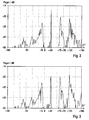
- the horseshoe base 10 With all converters of the horseshoe base 10 200 polar patterns are formed, whose Main reception directions a range of ⁇ 180 ° with respect to Cover the longitudinal axis of the submarine, with 0 ° the Alignment corresponds.
- the horseshoe base 10 is for a center frequency of broadband reception dimensioned to provide a panoramic view of the location to generate received broadband noise.
- the horseshoe base receives 10 sound impulses from Transmitters from other sonar systems are broadcast. This For example, sound pulses are monofrequency and point a frequency that is far above the center frequency of the receiving frequency range to be evaluated. Your Directions of reception should also be shown in the panoramic position are displayed.
- the direction generator 11 In the direction generator 11 are delayed Receive signals directional characteristic signals formed. level of the directional characteristic signals are in one Energy detector 12 compared and Polar pattern signals with the largest levels to one Display 13 switched to the location.
- an intercept signal analysis circuit 14 the detected Directional characteristic signals with regard to their frequency range, their modulation type, their pulse length or their Pulse repetition rate analyzed and when a received sound pulse in a circuit 15 for Determine their envelopes in the same direction.
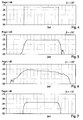
- the circuit 15 is a differentiating stage 16 and a maximum detector 17 subordinate, in which the slope of the envelope and their maximum can be determined. It will Directional characteristic signal determined, the envelope of which has the greatest slope.
- a downstream Logic logic 18 connected to the intercept signal analysis circuit 14 is connected, a display 13 driven on which the directional characteristic signal with a special identifier for the direction of incidence of a Sound pulse is displayed.
- the temporal courses of the envelopes in the Fig. 4-7 show in the area of the front and rear flanks of the Sound impulse different slopes.
Landscapes
- Physics & Mathematics (AREA)
- Engineering & Computer Science (AREA)
- General Physics & Mathematics (AREA)
- Radar, Positioning & Navigation (AREA)
- Remote Sensing (AREA)
- Measurement Of Velocity Or Position Using Acoustic Or Ultrasonic Waves (AREA)
Abstract
Description
- Fig.1
- ein Blockschaltbild,
- Fig.2
- ein Diagramm mit Richtcharakteristiksignalen in Abhängigkeit vom Winkel ihrer Empfangsrichtungen,
- Fig.3
- ein Diagramm wie in Fig.2 bei einem geringfügigen Versatz des Senders,
- Fig.4,5,6 und 7
- Einhüllende der Richtcharakteristiksignale in Abhängigkeit von der Zeit.
Claims (1)
- Verfahren zum Bestimmen der Einfallsrichtung empfangener Schallimpulse aus Empfangssignalen einer Sonarbasis mit einem Richtungsbildner zum Bilden von Richtcharakteristiksignalen durch Laufzeitkompensation der Empfangssignale sowie einer Intercept-Signal-Analyseschaltung zum Ermitteln von Richtcharakteristiksignalen mit impulsförmigem Signalinhalt, dadurch gekennzeichnet, daß die Einhüllende jedes Richtcharakteristiksignals, das einen impulsförmigen Signalinhalt aufweist, gebildet wird und die Steigungen der Einhüllenden bestimmt und verglichen werden, daß die Einhüllende mit der größten Steigung ermittelt wird und daß die Empfangsrichtung des zugehörigen Richtcharakteristiksignals der Einfallsrichtung des Schallimpulses zugeordnet wird.
Applications Claiming Priority (2)
| Application Number | Priority Date | Filing Date | Title |
|---|---|---|---|
| DE19745726 | 1997-10-16 | ||
| DE1997145726 DE19745726C1 (de) | 1997-10-16 | 1997-10-16 | Verfahren zum Bestimmen der Einfallsrichtung empfangener Schallimpulse |
Publications (2)
| Publication Number | Publication Date |
|---|---|
| EP0918231A2 true EP0918231A2 (de) | 1999-05-26 |
| EP0918231A3 EP0918231A3 (de) | 1999-12-01 |
Family
ID=7845717
Family Applications (1)
| Application Number | Title | Priority Date | Filing Date |
|---|---|---|---|
| EP98117951A Withdrawn EP0918231A3 (de) | 1997-10-16 | 1998-09-22 | Verfahren zum Bestimmen der Einfallsrichtung empfangener Schallimpulse |
Country Status (2)
| Country | Link |
|---|---|
| EP (1) | EP0918231A3 (de) |
| DE (1) | DE19745726C1 (de) |
Cited By (1)
| Publication number | Priority date | Publication date | Assignee | Title |
|---|---|---|---|---|
| CN114428225A (zh) * | 2022-04-06 | 2022-05-03 | 中国电子科技集团公司第二十九研究所 | 一种基于准匹配滤波的多辐射源到达角度测量方法及装置 |
Families Citing this family (1)
| Publication number | Priority date | Publication date | Assignee | Title |
|---|---|---|---|---|
| DE10128973C1 (de) * | 2001-06-15 | 2002-07-25 | Stn Atlas Elektronik Gmbh | U-Boot |
Family Cites Families (4)
| Publication number | Priority date | Publication date | Assignee | Title |
|---|---|---|---|---|
| US4207622A (en) * | 1978-04-13 | 1980-06-10 | The United States Of America As Represented By The Secretary Of The Navy | Direction-finding array of crossed dipoles |
| DE3150456A1 (de) * | 1981-12-19 | 1983-06-30 | Fried. Krupp Gmbh, 4300 Essen | Akustische unterwasserantenne |
| DE4141562A1 (de) * | 1991-12-17 | 1993-06-24 | Atlas Elektronik Gmbh | Vorrichtung zum peilen von propellerangetriebenen fahrzeugen |
| DE19612503C2 (de) * | 1996-03-29 | 1998-01-29 | Stn Atlas Elektronik Gmbh | Elektroakustischer Wandlermodul |
-
1997
- 1997-10-16 DE DE1997145726 patent/DE19745726C1/de not_active Expired - Fee Related
-
1998
- 1998-09-22 EP EP98117951A patent/EP0918231A3/de not_active Withdrawn
Non-Patent Citations (1)
| Title |
|---|
| KUEHNLE L.: "Classification and Identification - CAI - by Submarinesonars", NAVAL FORCES, no. VI, 1987, pages 28 - 31 * |
Cited By (2)
| Publication number | Priority date | Publication date | Assignee | Title |
|---|---|---|---|---|
| CN114428225A (zh) * | 2022-04-06 | 2022-05-03 | 中国电子科技集团公司第二十九研究所 | 一种基于准匹配滤波的多辐射源到达角度测量方法及装置 |
| CN114428225B (zh) * | 2022-04-06 | 2022-06-14 | 中国电子科技集团公司第二十九研究所 | 一种基于准匹配滤波的多辐射源到达角度测量方法及装置 |
Also Published As
| Publication number | Publication date |
|---|---|
| DE19745726C1 (de) | 1999-05-06 |
| EP0918231A3 (de) | 1999-12-01 |
Similar Documents
| Publication | Publication Date | Title |
|---|---|---|
| DE69529376T2 (de) | Vielfachlinien-Ultraschallbundelerregung mit verschachtelter Intervallabtastung | |
| DE3519254C2 (de) | ||
| DE69311193T2 (de) | Vergrösserung der Radar-Rückstrahlfläche mit phasenkonjugierten Impulssignalen | |
| DE10360889A1 (de) | System mit zwei oder mehr Sensoren | |
| DE102010056119B4 (de) | Akustische Unterwasserantenne, U-Boot mit derartiger Antenne sowie Verfahren zum Peilen, Orten und/oder Klassifizieren eines Ziels mittels einer derartigen Antenne | |
| DE3887745T2 (de) | Radargerät unter Verwendung von verschiedener Arten von Impulsen. | |
| EP0918231A2 (de) | Verfahren zum Bestimmen der Einfallsrichtung empfangener Schallimpulse | |
| EP2312333B1 (de) | Verfahren und Vorrichtungen zur Ortsbestimmung eines Objekts durch Reflektionserfassung von Wellenpulsen | |
| DE69106933T2 (de) | Gerät zur Festechounterdrückung für einen Ultraschallechograph. | |
| EP1001275B1 (de) | Vorrichtung zum Bestimmen der Einfallsrichtung von zeitlich begrenzt auftretenden Schallwellen | |
| DE10332886B3 (de) | Verfahren zum Bestimmen von Zieldaten mit einer Aktiv-Sonaranlage | |
| EP4410657A1 (de) | Unterseeboot und verfahren zur aktiven unterdrückung einer ortungsschallwelle | |
| EP1160581A1 (de) | Verfahren zum Bestimmen der Einfallsrichtung von Schallwellen | |
| EP0789252B1 (de) | Verfahren zur Unterdrückung von Störsignalen bei einem Pulsdopplerradar | |
| DE102022201395A1 (de) | Ermitteln einer Ursprungsrichtung von Schallsignalen | |
| DE4444942C2 (de) | Verfahren und Vorrichtung zur Unterwassertelefonie zwischen Wasserfahrzeugen | |
| DE4327841C1 (de) | Elektroakustisches Unterwasser-Peilgerät | |
| EP0702245B1 (de) | Verfahren zur Befreiung von Körperschallstörungen | |
| DE4141562A1 (de) | Vorrichtung zum peilen von propellerangetriebenen fahrzeugen | |
| DE19825271C1 (de) | Verfahren zur passiven Bestimmung von Zieldaten | |
| EP0597194A2 (de) | Luftschallecholot | |
| EP0660130B1 (de) | Verfahren zum Peilen von impulsförmig Schallwellen abstrahlenden Zielen | |
| DE4409117C2 (de) | Echolot | |
| EP0249036A2 (de) | Verfahren zur Echolaufzeitbestimmung | |
| EP2527870B1 (de) | Verfahren und Vorrichtung zur Detektion eines oder mehrerer festgelegter Impulse oder Impulsfolgen in einem Empfangs- oder Gruppensignal sowie Aktivsonaranlage |
Legal Events
| Date | Code | Title | Description |
|---|---|---|---|
| PUAI | Public reference made under article 153(3) epc to a published international application that has entered the european phase |
Free format text: ORIGINAL CODE: 0009012 |
|
| AK | Designated contracting states |
Kind code of ref document: A2 Designated state(s): FR GB IT NL SE |
|
| AX | Request for extension of the european patent |
Free format text: AL;LT;LV;MK;RO;SI |
|
| PUAL | Search report despatched |
Free format text: ORIGINAL CODE: 0009013 |
|
| AK | Designated contracting states |
Kind code of ref document: A3 Designated state(s): AT BE CH CY DE DK ES FI FR GB GR IE IT LI LU MC NL PT SE |
|
| AX | Request for extension of the european patent |
Free format text: AL;LT;LV;MK;RO;SI |
|
| RIC1 | Information provided on ipc code assigned before grant |
Free format text: 6G 01S 3/803 A, 6G 01S 3/808 B |
|
| 17P | Request for examination filed |
Effective date: 19991215 |
|
| AKX | Designation fees paid |
Free format text: FR GB IT NL SE |
|
| RBV | Designated contracting states (corrected) |
Designated state(s): DE FR GB IT NL |
|
| RBV | Designated contracting states (corrected) |
Designated state(s): FR GB IT NL SE |
|
| REG | Reference to a national code |
Ref country code: DE Ref legal event code: 8566 |
|
| 17Q | First examination report despatched |
Effective date: 20010620 |
|
| GRAG | Despatch of communication of intention to grant |
Free format text: ORIGINAL CODE: EPIDOS AGRA |
|
| STAA | Information on the status of an ep patent application or granted ep patent |
Free format text: STATUS: THE APPLICATION HAS BEEN WITHDRAWN |
|
| 18W | Application withdrawn |
Withdrawal date: 20020710 |