EP0918145A2 - Exhaust emission control catalyst apparatus in internal combustion engine - Google Patents
Exhaust emission control catalyst apparatus in internal combustion engine Download PDFInfo
- Publication number
- EP0918145A2 EP0918145A2 EP98121499A EP98121499A EP0918145A2 EP 0918145 A2 EP0918145 A2 EP 0918145A2 EP 98121499 A EP98121499 A EP 98121499A EP 98121499 A EP98121499 A EP 98121499A EP 0918145 A2 EP0918145 A2 EP 0918145A2
- Authority
- EP
- European Patent Office
- Prior art keywords
- catalytic converter
- way catalytic
- converter layer
- adsorption material
- layer
- Prior art date
- Legal status (The legal status is an assumption and is not a legal conclusion. Google has not performed a legal analysis and makes no representation as to the accuracy of the status listed.)
- Granted
Links
Images


Classifications
-
- F—MECHANICAL ENGINEERING; LIGHTING; HEATING; WEAPONS; BLASTING
- F01—MACHINES OR ENGINES IN GENERAL; ENGINE PLANTS IN GENERAL; STEAM ENGINES
- F01N—GAS-FLOW SILENCERS OR EXHAUST APPARATUS FOR MACHINES OR ENGINES IN GENERAL; GAS-FLOW SILENCERS OR EXHAUST APPARATUS FOR INTERNAL COMBUSTION ENGINES
- F01N3/00—Exhaust or silencing apparatus having means for purifying, rendering innocuous, or otherwise treating exhaust
- F01N3/08—Exhaust or silencing apparatus having means for purifying, rendering innocuous, or otherwise treating exhaust for rendering innocuous
- F01N3/0807—Exhaust or silencing apparatus having means for purifying, rendering innocuous, or otherwise treating exhaust for rendering innocuous by using absorbents or adsorbents
- F01N3/0828—Exhaust or silencing apparatus having means for purifying, rendering innocuous, or otherwise treating exhaust for rendering innocuous by using absorbents or adsorbents characterised by the absorbed or adsorbed substances
- F01N3/0835—Hydrocarbons
-
- F—MECHANICAL ENGINEERING; LIGHTING; HEATING; WEAPONS; BLASTING
- F01—MACHINES OR ENGINES IN GENERAL; ENGINE PLANTS IN GENERAL; STEAM ENGINES
- F01N—GAS-FLOW SILENCERS OR EXHAUST APPARATUS FOR MACHINES OR ENGINES IN GENERAL; GAS-FLOW SILENCERS OR EXHAUST APPARATUS FOR INTERNAL COMBUSTION ENGINES
- F01N13/00—Exhaust or silencing apparatus characterised by constructional features ; Exhaust or silencing apparatus, or parts thereof, having pertinent characteristics not provided for in, or of interest apart from, groups F01N1/00 - F01N5/00, F01N9/00, F01N11/00
- F01N13/009—Exhaust or silencing apparatus characterised by constructional features ; Exhaust or silencing apparatus, or parts thereof, having pertinent characteristics not provided for in, or of interest apart from, groups F01N1/00 - F01N5/00, F01N9/00, F01N11/00 having two or more separate purifying devices arranged in series
- F01N13/0097—Exhaust or silencing apparatus characterised by constructional features ; Exhaust or silencing apparatus, or parts thereof, having pertinent characteristics not provided for in, or of interest apart from, groups F01N1/00 - F01N5/00, F01N9/00, F01N11/00 having two or more separate purifying devices arranged in series the purifying devices are arranged in a single housing
-
- F—MECHANICAL ENGINEERING; LIGHTING; HEATING; WEAPONS; BLASTING
- F01—MACHINES OR ENGINES IN GENERAL; ENGINE PLANTS IN GENERAL; STEAM ENGINES
- F01N—GAS-FLOW SILENCERS OR EXHAUST APPARATUS FOR MACHINES OR ENGINES IN GENERAL; GAS-FLOW SILENCERS OR EXHAUST APPARATUS FOR INTERNAL COMBUSTION ENGINES
- F01N3/00—Exhaust or silencing apparatus having means for purifying, rendering innocuous, or otherwise treating exhaust
- F01N3/08—Exhaust or silencing apparatus having means for purifying, rendering innocuous, or otherwise treating exhaust for rendering innocuous
- F01N3/0807—Exhaust or silencing apparatus having means for purifying, rendering innocuous, or otherwise treating exhaust for rendering innocuous by using absorbents or adsorbents
- F01N3/0814—Exhaust or silencing apparatus having means for purifying, rendering innocuous, or otherwise treating exhaust for rendering innocuous by using absorbents or adsorbents combined with catalytic converters, e.g. NOx absorption/storage reduction catalysts
-
- F—MECHANICAL ENGINEERING; LIGHTING; HEATING; WEAPONS; BLASTING
- F01—MACHINES OR ENGINES IN GENERAL; ENGINE PLANTS IN GENERAL; STEAM ENGINES
- F01N—GAS-FLOW SILENCERS OR EXHAUST APPARATUS FOR MACHINES OR ENGINES IN GENERAL; GAS-FLOW SILENCERS OR EXHAUST APPARATUS FOR INTERNAL COMBUSTION ENGINES
- F01N2250/00—Combinations of different methods of purification
- F01N2250/12—Combinations of different methods of purification absorption or adsorption, and catalytic conversion
-
- F—MECHANICAL ENGINEERING; LIGHTING; HEATING; WEAPONS; BLASTING
- F01—MACHINES OR ENGINES IN GENERAL; ENGINE PLANTS IN GENERAL; STEAM ENGINES
- F01N—GAS-FLOW SILENCERS OR EXHAUST APPARATUS FOR MACHINES OR ENGINES IN GENERAL; GAS-FLOW SILENCERS OR EXHAUST APPARATUS FOR INTERNAL COMBUSTION ENGINES
- F01N2570/00—Exhaust treating apparatus eliminating, absorbing or adsorbing specific elements or compounds
- F01N2570/12—Hydrocarbons
-
- Y—GENERAL TAGGING OF NEW TECHNOLOGICAL DEVELOPMENTS; GENERAL TAGGING OF CROSS-SECTIONAL TECHNOLOGIES SPANNING OVER SEVERAL SECTIONS OF THE IPC; TECHNICAL SUBJECTS COVERED BY FORMER USPC CROSS-REFERENCE ART COLLECTIONS [XRACs] AND DIGESTS
- Y02—TECHNOLOGIES OR APPLICATIONS FOR MITIGATION OR ADAPTATION AGAINST CLIMATE CHANGE
- Y02T—CLIMATE CHANGE MITIGATION TECHNOLOGIES RELATED TO TRANSPORTATION
- Y02T10/00—Road transport of goods or passengers
- Y02T10/10—Internal combustion engine [ICE] based vehicles
- Y02T10/12—Improving ICE efficiencies
Definitions
- the present invention relates to an exhaust emission control catalyst apparatus in an internal combustion engine, and more particularly, to a technique for enhancing a conversion performance of HC (hydrocarbon) by a HC adsorption catalyst when it is cold.
- this exhaust emission control apparatus utilizing property of the HC adsorption material that the HC adsorption material adsorbs HC when temperature is low and eliminates HC when temperature rises to a fixed temperature, cold HC is adsorbed by the HC adsorption material, and when the exhaust temperature rises to the fixed value, the HC eliminated from the HC adsorption material is purified by the three way catalytic converter.
- temperature rise of the HC adsorption material located upstream the exhaust passage is faster than that of the three way catalytic converter located downstream.
- Another prior art includes the HC adsorption material upstream the exhaust passage, and exhaust emission catalyst for purifying the HC downstream the exhaust passage (Japanese Patent Application Laid-open No. 8-284646).
- heat capacity of the exhaust emission catalyst to a value smaller than heat capacity of the HC adsorption material, temperature rise of the exhaust emission catalyst located downstream is made faster than that of the HC adsorption material.
- the emission control catalyst can reach the activating temperature before the upstream end of the HC adsorption material which is most liable to receive the heat of the exhaust gas reaches the elimination temperature, it is possible to mostly purify the HC eliminated from the HC adsorption material. However, it is practically difficult to increase the difference in heat capacity to such an extent.
- HC adsorption catalyst in which a layer of catalyst for purifying HC is formed above a layer of HC adsorption material (Japanese Patent Application Laid-open No.8-224449).
- Japanese Patent Application Laid-open No.8-224449 Japanese Patent Application Laid-open No.8-224449.
- the HC passes the catalyst layer without fail, and temperature of the upper catalyst layer which directly contact with the exhaust gas rises faster than the lower HC adsorption material layer.
- the upper catalyst layer reaches the complete activating temperature when the lower HC adsorption material reaches the elimination temperature, it is possible to mostly purify the HC.
- the HC elimination temperature of zeolite which is used as the HC adsorption material at the present is much lower than the activating temperature, when the HC adsorption material layer reaches the elimination temperature, the catalyst layer does not reach the complete activating state and therefore, it is not possible to purify all the eliminated HC by the catalyst layer.
- a HC adsorption catalyst comprising a three way catalytic converter layer 2 disposed on a HC adsorption material 1 (not prior art), but such a HC adsorption catalyst has the following problems.
- the three way catalytic converter starts activating.
- the temperature of the three way catalytic converter layer 2 rises from a portion thereof located at upstream of exhaust flow, the elimination of HC which has been adsorbed by the HC adsorption material 1 is started, and among the HC which is once eliminated, a portion thereof which is not converted by the three way catalytic converter layer is again adsorbed by the rear portion of the HC adsorption material 1 where the temperature of the three way catalytic converter layer 2 is low.
- the HC repeats elimination, re-adsorption, elimination, re-adsorption, ... on a portion of the HC adsorption catalyst downstream of the exhaust flow, and the HC finally reaches the downstream end of the HC adsorption catalyst and is discharged out and therefore, it is not possible to suppress the HC from being discharged when it is cold.
- a HC (hydrocarbon) adsorption catalyst having the three way catalytic converter coated on the HC adsorption material is used, and the conversion performance of the HC when it is cold is enhanced by improvement of the HC adsorption catalyst, and it is possible to effectively suppress the discharge of the HC.
- an exhaust emission control catalyst apparatus in an internal combustion engine comprising:
- the three way catalytic converter starts activating.
- the temperature of the three way catalytic converter layer rises from a portion thereof located at upstream of exhaust flow, the elimination of HC which has been adsorbed by the HC adsorption material is started, and the HC which is once eliminated is again adsorbed by the rear portion of the HC adsorption material where the temperature of the three way catalytic converter layer is low.
- the HC repeats elimination, re-adsorption, elimination, re-adsorption, ... from the portion of the HC adsorption catalyst upstream of the exhaust flow, finally reaches the downstream end of the portion X including the three way catalytic converter layer on the HC adsorption material. Since the downstream end of this portion X is provided with the three way catalytic converter layer Y, the HC is converted by the three way catalytic converter layer of this portion Y.
- the exhaust gas heat can be used for the temperature rise of the catalyst composition only. Therefore, it is possible to obtain activity state better than the upstream three way catalytic converter layer formed on the HC adsorption material layer.
- the three way catalytic converter layer which is not formed at its lower layer with the HC adsorption material layer need not be in an excellent activity state when the upstream end of the HC adsorption material layer reaches the elimination temperature, and such a portion suffices if it is in the excellent activity state when the downstream end portion of the HC adsorption material layer reaches the elimination temperature. Further, the amount of HC which should be converted by this three way catalytic converter layer is very small, the increase amount of catalyst composition which must be carried due to the provision of the three way catalytic converter layer is also small.
- the HC which could not be converted by a portion of the HC adsorption material provided thereon with the three way catalytic converter layer can effectively be converted by the three way catalytic converter layer just downstream of the portion, and it is possible to suppress the discharge of the HC when it is cold.
- the downstream side three way catalytic converter layer may be formed by extending the upstream side three way catalytic converter layer on the hydrocarbon adsorption material to a position extended in a further downstream direction from a downstream end of the hydrocarbon adsorption material.
- the three way catalytic converter layer can easily be formed by merely extending the three way catalytic converter layer on the HC adsorption material.
- downstream side three way catalytic converter layer may be formed by providing an independent three way catalytic converter layer on a position close to a downstream end of the upstream side three way catalytic converter layer on the hydrocarbon adsorption material.
- the three way catalytic converter layer can easily be formed by adding the independent three way catalytic converter layer on the position close to the downstream end portion of the HC adsorption material provided thereon with the three way catalytic converter layer.
- downstream side three way catalytic converter layer may comprise a high carrier three way catalytic converter layer carrying catalyst at a density higher than that of the upstream side three way catalytic converter layer on the hydrocarbon adsorption material.
- downstream side three way catalytic converter layer is coated with a high carrier three way catalytic converter layer carrying catalyst at a density higher than the downstream side three way catalytic converter layer.
- the conversion performance of the HC of the three way catalytic converter layer is enhanced. Further, the three way catalytic converter layer can easily be formed by the high carrier three way catalytic converter layer.
- the honeycomb carrier may include an upstream side honeycomb carrier and a downstream honeycomb carrier, the upstream side honeycomb carrier and the downstream side honeycomb carrier are adjacently disposed, the hydrocarbon adsorption material layer and the upstream side three way catalytic converter layer are disposed on the upstream side honeycomb carrier, and the downstream side three way catalytic converter layer is disposed on the downstream side honeycomb carrier.
- downstream side three way catalytic converter layer may carry catalyst of a density higher than that of the upstream side three way catalytic converter layer.
- the wall thickness of the downstream side honeycomb carrier may be formed thinner than that of the upstream side honeycomb carrier.
- Fig.2 is an arrangement plan view showing HC (hydrocarbon) adsorption catalyst of an embodiment of the exhaust emission control catalyst apparatus according to the present invention.
- an exhaust passage 3 is extended from an engine 1, and is provided at its intermediate portion with a HC adsorption catalyst 10.
- Fig. 3 is a perspective view showing the entire structure of the HC adsorption catalyst apparatus of the embodiment of the exhaust emission control catalyst apparatus 10 of the invention, and each cell 12 of a honeycomb carrier 11 is coated with a catalyst layer.
- Figs. 4 and 5 show a structure of the catalyst layer of the cell 12 of the honeycomb carrier 11, wherein Fig.4 is a sectional view along a direction of exhaust flow of the cell 12, and Fig.5 is a sectional view along a direction perpendicular to the direction of exhaust flow of the cell 12, taken along the line V-V in Fig.4.
- an inner surface of the cell 12 of the honeycomb carrier 11 is coated with HC adsorption material 13 such as zeolite except a downstream end of the inner surface in the exhaust flow direction, and the entire inner surface of the cell 12 coated with the HC adsorption material 13 is coated with three way catalytic converter layer 14 such as palladium, rhodium as precious metal catalyst.
- HC adsorption material 13 such as zeolite except a downstream end of the inner surface in the exhaust flow direction
- three way catalytic converter layer 14 such as palladium, rhodium as precious metal catalyst.
- the three way catalytic converter layer 14 is extended from the downstream end to a position further extended to downstream of the HC adsorption material 13, and a portion X located upstream side of the exhaust flow and having the three way catalytic converter layer 14 on the HC adsorption material 13, and a three way catalytic converter layer portion Y located downstream side of the exhaust flow are formed on an inner surface of the cell 12 of the honeycomb carrier 11.
- the HC is adsorbed by the entire HC adsorption material 13.
- the three way catalytic converter layer 14 starts activating.
- the temperature of the three way catalytic converter layer 14 rises from its portion located upstream of the exhaust flow, the elimination of the HC adsorbed by the HC adsorption material 13 is started, a portion of the HC which was once eliminated is converted by the three way catalytic converter layer 14, and the remaining HC is again adsorbed by the rear flow portion of the three way catalytic converter layer 14, which is the HC adsorption material 13 whose temperature is low.
- the HC repeats elimination, re-adsorption, elimination, re-adsorption, ... from the portion of the HC adsorption catalyst 10 upstream of the exhaust flow, finally reaches the downstream end of the portion X including the three way catalytic converter layer 14 on the HC adsorption material 13. Since the downstream end of this portion X is provided with the three way catalytic converter layer portion Y, the HC is converted by the three way catalytic converter layer 14 of this portion Y.
- a small amount of the three way catalytic converter layer portion Y suffices because the three way catalytic converter layer portion Y is only required to convert the HC in an amount which could not be converted by the three way catalytic converter layer 14.
- the three way catalytic converter layer portion Y comprises a high carrier three way catalytic converter layer in which catalyst having density higher than that of the upper three way catalytic converter layer 14 of the HC adsorption material 13 is carried.
- a high carrier three way catalytic converter layer 15 in which catalyst having density higher than that of the upper three way catalytic converter layer 14 may be coated on the three way catalytic converter layer portion Y.
- the HC adsorption catalyst 10 may be formed by providing an independent three way catalytic converter layer 16 as the three way catalytic converter layer portion Y in a position close to the downstream end of the portion X including the three way catalytic converter layer 14 on the HC adsorption material 13.
- the inner surface of the cell 12 is coated with the HC adsorption material 13 except its downstream end, and the three way catalytic converter layer 14 is coated on the HC adsorption material 13, and the three way catalytic converter layer 16 is coated on the downstream end of the inner surface of the cell 12.
- an upstream side honeycomb carrier 11a and a downstream side honeycomb carrier 11b are divided.
- the portion X having the three way catalytic converter 14 on the HC adsorption material 13 of an upstream side cell 12a is coated, and the portion Y of a downstream side cell 12b having the three way catalytic converter layer 16 of a density higher than that of the upstream side cell 12a is coated.
- the downstream side three way catalytic converter layer 16 is formed such that a surface area thereof (area contacted with exhaust gas) is large.
- a wall thickness of the downstream side honeycomb carrier 11b is formed thinner than that of the upstream side honeycomb carrier 11a, and a heat capacity of the downstream side honeycomb carrier 11b is set to a small value.
Abstract
Description
- The present invention relates to an exhaust emission control catalyst apparatus in an internal combustion engine, and more particularly, to a technique for enhancing a conversion performance of HC (hydrocarbon) by a HC adsorption catalyst when it is cold.
- Conventionally, there is a known exhaust emission control apparatus in which a HC (hydrocarbon) adsorption material is interposed in an exhaust passage of an internal combustion engine, the HC in exhaust is adsorbed by the HC adsorption material when it is cold, the HC is eliminated from the HC adsorption material after warming up of the engine, the eliminated HC is purified by three way catalytic converter or oxidizing catalyst disposed at the exhaust downstream of the HC adsorption material (see Japanese Patent Application Laid-open No. 5-59942 and the like).
- That is, in this exhaust emission control apparatus, utilizing property of the HC adsorption material that the HC adsorption material adsorbs HC when temperature is low and eliminates HC when temperature rises to a fixed temperature, cold HC is adsorbed by the HC adsorption material, and when the exhaust temperature rises to the fixed value, the HC eliminated from the HC adsorption material is purified by the three way catalytic converter.
- However, the exhaust emission control apparatus having the above described conventional HC adsorption material has the following problem.
- That is, temperature rise of the HC adsorption material located upstream the exhaust passage is faster than that of the three way catalytic converter located downstream.
- Therefore, when the elimination of the HC from the HC adsorption material is started, if a rear three way catalytic converter or oxidizing catalyst does not reach the activating temperature, there is an unfavorable possibility that the eliminated HC is not converted and is discharged, and discharge of the HC when it is cold can not be suppressed.
- Further, another prior art includes the HC adsorption material upstream the exhaust passage, and exhaust emission catalyst for purifying the HC downstream the exhaust passage (Japanese Patent Application Laid-open No. 8-284646). In this prior art, by controlling heat capacity of the exhaust emission catalyst to a value smaller than heat capacity of the HC adsorption material, temperature rise of the exhaust emission catalyst located downstream is made faster than that of the HC adsorption material.
- In this case, if the emission control catalyst can reach the activating temperature before the upstream end of the HC adsorption material which is most liable to receive the heat of the exhaust gas reaches the elimination temperature, it is possible to mostly purify the HC eliminated from the HC adsorption material. However, it is practically difficult to increase the difference in heat capacity to such an extent.
- Another prior art is provided with HC adsorption catalyst in which a layer of catalyst for purifying HC is formed above a layer of HC adsorption material (Japanese Patent Application Laid-open No.8-224449). In this prior art, when the HC adsorbed by the HC adsorption material layer is eliminated, the HC passes the catalyst layer without fail, and temperature of the upper catalyst layer which directly contact with the exhaust gas rises faster than the lower HC adsorption material layer.
- In this case, if the upper catalyst layer reaches the complete activating temperature when the lower HC adsorption material reaches the elimination temperature, it is possible to mostly purify the HC. However, since the HC elimination temperature of zeolite which is used as the HC adsorption material at the present is much lower than the activating temperature, when the HC adsorption material layer reaches the elimination temperature, the catalyst layer does not reach the complete activating state and therefore, it is not possible to purify all the eliminated HC by the catalyst layer.
- In such a HC adsorption catalyst also, since the temperature rises from the upstream side which is most liable to receive heat of the exhaust gas, the elimination of the HC is started from the upstream side with the temperature rise. Among the eliminated HC, a portion thereof which is not purified by the catalyst layer is again adsorbed by the downstream side whose temperature has not risen yet and therefore, such HC should not be discharged to open air as it is. However, when a portion of the HC adsorption material layer in the vicinity of its downstream side also reaches the elimination temperature, the HC which is eliminated from the vicinity of the downstream side and which is not purified by the catalyst layer is discharged to open air as it is.
- Meanwhile, as shown in Fig.1, there is proposed a HC adsorption catalyst comprising a three way
catalytic converter layer 2 disposed on a HC adsorption material 1 (not prior art), but such a HC adsorption catalyst has the following problems. - That is, after the engine is started in a cold state, when the temperature of the HC adsorption catalyst is low, HC is adsorbed by the
HC adsorption material 1 entirely, and when the warming up of the engine progresses and the exhaust temperature rises, the three way catalytic converter starts activating. The temperature of the three waycatalytic converter layer 2 rises from a portion thereof located at upstream of exhaust flow, the elimination of HC which has been adsorbed by theHC adsorption material 1 is started, and among the HC which is once eliminated, a portion thereof which is not converted by the three way catalytic converter layer is again adsorbed by the rear portion of theHC adsorption material 1 where the temperature of the three waycatalytic converter layer 2 is low. When the temperature of the three waycatalytic converter layer 2 of this rear portion rises, the elimination of the HC which was again adsorbed by theHC adsorption material 1 is started, a portion of the HC is converted by the three way catalytic converter layer, and the remaining HC is again adsorbed by a further rear portion of theHC adsorption material 1 where the temperature of the three waycatalytic converter layer 2 is low. - As described above, the HC repeats elimination, re-adsorption, elimination, re-adsorption, ... on a portion of the HC adsorption catalyst downstream of the exhaust flow, and the HC finally reaches the downstream end of the HC adsorption catalyst and is discharged out and therefore, it is not possible to suppress the HC from being discharged when it is cold.
- It is therefore an object of the present invention to provide an exhaust emission control catalyst apparatus in an internal combustion engine, in which a HC (hydrocarbon) adsorption catalyst having the three way catalytic converter coated on the HC adsorption material is used, and the conversion performance of the HC when it is cold is enhanced by improvement of the HC adsorption catalyst, and it is possible to effectively suppress the discharge of the HC.
- To achieve the above problems, there is provided an exhaust emission control catalyst apparatus in an internal combustion engine, comprising:
- a honeycomb carrier;
- a hydrocarbon adsorption material layer disposed on an upstream side of the honeycomb carrier;
- an upstream side three way catalytic converter layer disposed on the hydrocarbon adsorption material layer; and
- a downstream side three way catalytic converter layer disposed on a downstream side of the honeycomb carrier adjacent the hydrocarbon adsorption material layer.
-
- Operations of the present invention will be explained.
- After the engine is started in a cold state, when the temperature of the HC adsorption catalyst is low, HC is adsorbed by the HC adsorption material entirely, and when the warming up of the engine progresses and the exhaust temperature rises, the three way catalytic converter starts activating. The temperature of the three way catalytic converter layer rises from a portion thereof located at upstream of exhaust flow, the elimination of HC which has been adsorbed by the HC adsorption material is started, and the HC which is once eliminated is again adsorbed by the rear portion of the HC adsorption material where the temperature of the three way catalytic converter layer is low. When the temperature of the three way catalytic converter layer of this rear portion rises , the elimination of the HC which was adsorbed by the HC adsorption material is started, the eliminated HC is again adsorbed by a further rear portion of the HC adsorption material where the temperature of the three way catalytic converter layer is low.
- As described above, the HC repeats elimination, re-adsorption, elimination, re-adsorption, ... from the portion of the HC adsorption catalyst upstream of the exhaust flow, finally reaches the downstream end of the portion X including the three way catalytic converter layer on the HC adsorption material. Since the downstream end of this portion X is provided with the three way catalytic converter layer Y, the HC is converted by the three way catalytic converter layer of this portion Y.
- Since the most downstream side three way catalytic converter layer is not formed at its lower layer with the HC adsorption material layer, the exhaust gas heat can be used for the temperature rise of the catalyst composition only. Therefore, it is possible to obtain activity state better than the upstream three way catalytic converter layer formed on the HC adsorption material layer.
- The three way catalytic converter layer which is not formed at its lower layer with the HC adsorption material layer need not be in an excellent activity state when the upstream end of the HC adsorption material layer reaches the elimination temperature, and such a portion suffices if it is in the excellent activity state when the downstream end portion of the HC adsorption material layer reaches the elimination temperature. Further, the amount of HC which should be converted by this three way catalytic converter layer is very small, the increase amount of catalyst composition which must be carried due to the provision of the three way catalytic converter layer is also small.
- According to the present invention, the HC which could not be converted by a portion of the HC adsorption material provided thereon with the three way catalytic converter layer can effectively be converted by the three way catalytic converter layer just downstream of the portion, and it is possible to suppress the discharge of the HC when it is cold.
- In a preferred embodiment, the downstream side three way catalytic converter layer may be formed by extending the upstream side three way catalytic converter layer on the hydrocarbon adsorption material to a position extended in a further downstream direction from a downstream end of the hydrocarbon adsorption material.
- With this configuration, the three way catalytic converter layer can easily be formed by merely extending the three way catalytic converter layer on the HC adsorption material.
- Further, the downstream side three way catalytic converter layer may be formed by providing an independent three way catalytic converter layer on a position close to a downstream end of the upstream side three way catalytic converter layer on the hydrocarbon adsorption material.
- With this configuration, the three way catalytic converter layer can easily be formed by adding the independent three way catalytic converter layer on the position close to the downstream end portion of the HC adsorption material provided thereon with the three way catalytic converter layer.
- Further, the downstream side three way catalytic converter layer may comprise a high carrier three way catalytic converter layer carrying catalyst at a density higher than that of the upstream side three way catalytic converter layer on the hydrocarbon adsorption material.
- With this configuration, it is possible to obtain the high HC conversion performance while suppressing the costs.
- Furthermore, the downstream side three way catalytic converter layer is coated with a high carrier three way catalytic converter layer carrying catalyst at a density higher than the downstream side three way catalytic converter layer.
- With these configuration, the conversion performance of the HC of the three way catalytic converter layer is enhanced. Further, the three way catalytic converter layer can easily be formed by the high carrier three way catalytic converter layer.
- Furthermore, the honeycomb carrier may include an upstream side honeycomb carrier and a downstream honeycomb carrier, the upstream side honeycomb carrier and the downstream side honeycomb carrier are adjacently disposed, the hydrocarbon adsorption material layer and the upstream side three way catalytic converter layer are disposed on the upstream side honeycomb carrier, and the downstream side three way catalytic converter layer is disposed on the downstream side honeycomb carrier.
- Moreover, the downstream side three way catalytic converter layer may carry catalyst of a density higher than that of the upstream side three way catalytic converter layer.
- Further, the wall thickness of the downstream side honeycomb carrier may be formed thinner than that of the upstream side honeycomb carrier.
-
- Fig. 1 is a sectional view of a conventional HC adsorption catalyst along a direction of exhaust flow of one cell;
- Fig.2 is an arrangement plan view showing an embodiment of the exhaust emission control catalyst apparatus according to the present invention;
- Fig.3 is a perspective view showing the entire structure of the HC adsorption catalyst;
- Fig.4 is a sectional view of a HC adsorption catalyst along a direction of exhaust flow of one cell, showing a structure of the HC adsorption catalyst of the embodiment of the exhaust emission control catalyst apparatus of the present invention;
- Fig.5 is a sectional view along a direction perpendicular to the direction of exhaust flow of one cell, taken along the line V-V in Fig. 4;
- Fig.6 is a sectional view of a HC adsorption catalyst along a direction of exhaust flow of one cell showing another embodiment;
- Fig.7 is a sectional view of a HC adsorption catalyst along a direction of exhaust flow of one cell showing further another embodiment; and
- Fig.8 is a sectional view of a HC adsorption catalyst along a direction of exhaust flow of one cell showing furthermore another embodiment.
-
- The present invention will be explained in detail below with reference to the accompanying drawings.
- Fig.2 is an arrangement plan view showing HC (hydrocarbon) adsorption catalyst of an embodiment of the exhaust emission control catalyst apparatus according to the present invention. As shown in Fig.2, an
exhaust passage 3 is extended from anengine 1, and is provided at its intermediate portion with aHC adsorption catalyst 10. - Fig. 3 is a perspective view showing the entire structure of the HC adsorption catalyst apparatus of the embodiment of the exhaust emission
control catalyst apparatus 10 of the invention, and eachcell 12 of ahoneycomb carrier 11 is coated with a catalyst layer. - Figs. 4 and 5 show a structure of the catalyst layer of the
cell 12 of thehoneycomb carrier 11, wherein Fig.4 is a sectional view along a direction of exhaust flow of thecell 12, and Fig.5 is a sectional view along a direction perpendicular to the direction of exhaust flow of thecell 12, taken along the line V-V in Fig.4. - In these drawings, an inner surface of the
cell 12 of thehoneycomb carrier 11 is coated withHC adsorption material 13 such as zeolite except a downstream end of the inner surface in the exhaust flow direction, and the entire inner surface of thecell 12 coated with theHC adsorption material 13 is coated with three waycatalytic converter layer 14 such as palladium, rhodium as precious metal catalyst. - By such a coating method of the
HC adsorption material 13 and the three waycatalytic converter layer 14, the three waycatalytic converter layer 14 is extended from the downstream end to a position further extended to downstream of theHC adsorption material 13, and a portion X located upstream side of the exhaust flow and having the three waycatalytic converter layer 14 on theHC adsorption material 13, and a three way catalytic converter layer portion Y located downstream side of the exhaust flow are formed on an inner surface of thecell 12 of thehoneycomb carrier 11. - Next, an operation of the
HC adsorption catalyst 10 of such a structure will be explained. - After cold start of the engine, when the temperature of the
HC adsorption catalyst 10 is low, the HC is adsorbed by the entireHC adsorption material 13. When the warming up of the engine is continued and the exhaust temperature rises, the three waycatalytic converter layer 14 starts activating. The temperature of the three waycatalytic converter layer 14 rises from its portion located upstream of the exhaust flow, the elimination of the HC adsorbed by theHC adsorption material 13 is started, a portion of the HC which was once eliminated is converted by the three waycatalytic converter layer 14, and the remaining HC is again adsorbed by the rear flow portion of the three waycatalytic converter layer 14, which is theHC adsorption material 13 whose temperature is low. When the temperature of the rear portion of the three waycatalytic converter layer 14 rises, the HC which was adsorbed by theHC adsorption material 13 starts to be eliminated, and similarly, the HC which was not converted by the three waycatalytic converter layer 14 and was eliminated is again adsorbed by a further rear flow portion of the three waycatalytic converter layer 14, which is theHC adsorption material 13 whose temperature is lower. - As described above, the HC repeats elimination, re-adsorption, elimination, re-adsorption, ... from the portion of the
HC adsorption catalyst 10 upstream of the exhaust flow, finally reaches the downstream end of the portion X including the three waycatalytic converter layer 14 on theHC adsorption material 13. Since the downstream end of this portion X is provided with the three way catalytic converter layer portion Y, the HC is converted by the three waycatalytic converter layer 14 of this portion Y. - Therefore, it is possible to suppress the HC from being discharged from the downstream end of the
HC adsorption catalyst 10, and to suppress the HC from being discharged when it is cold. - A small amount of the three way catalytic converter layer portion Y suffices because the three way catalytic converter layer portion Y is only required to convert the HC in an amount which could not be converted by the three way
catalytic converter layer 14. - It is preferable that the three way catalytic converter layer portion Y comprises a high carrier three way catalytic converter layer in which catalyst having density higher than that of the upper three way
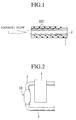
catalytic converter layer 14 of theHC adsorption material 13 is carried. In this case, as shown in Fig. 6, a high carrier three waycatalytic converter layer 15 in which catalyst having density higher than that of the upper three waycatalytic converter layer 14 may be coated on the three way catalytic converter layer portion Y. - With this feature, it is possible to insure the high HC conversion performance while suppressing the costs.
- Although the three way catalytic converter layer portion Y is formed by extending the three way
catalytic converter layer 14 of theHC adsorption material 13 up to the position extended further downstream from the downstream end of theHC adsorption material 13, as shown in Fig. 7, theHC adsorption catalyst 10 may be formed by providing an independent three waycatalytic converter layer 16 as the three way catalytic converter layer portion Y in a position close to the downstream end of the portion X including the three waycatalytic converter layer 14 on theHC adsorption material 13. - In this case, the inner surface of the
cell 12 is coated with theHC adsorption material 13 except its downstream end, and the three waycatalytic converter layer 14 is coated on theHC adsorption material 13, and the three waycatalytic converter layer 16 is coated on the downstream end of the inner surface of thecell 12. - In another embodiment shown in Fig. 8, an upstream
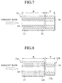
side honeycomb carrier 11a and a downstreamside honeycomb carrier 11b are divided. The portion X having the three waycatalytic converter 14 on theHC adsorption material 13 of anupstream side cell 12a is coated, and the portion Y of adownstream side cell 12b having the three waycatalytic converter layer 16 of a density higher than that of theupstream side cell 12a is coated. The downstream side three waycatalytic converter layer 16 is formed such that a surface area thereof (area contacted with exhaust gas) is large. A wall thickness of the downstreamside honeycomb carrier 11b is formed thinner than that of the upstreamside honeycomb carrier 11a, and a heat capacity of the downstreamside honeycomb carrier 11b is set to a small value. With this arrangement, it is possible to further enhance the activation of the three waycatalytic converter layer 16 when the downstream end portion of the HCadsorption material layer 13 reaches the elimination temperature.
Claims (8)
- An exhaust emission control catalyst apparatus in an internal combustion engine, comprising:a honeycomb carrier;a hydrocarbon adsorption material layer disposed on an upstream side of said honeycomb carrier;an upstream side three way catalytic converter layer disposed on said hydrocarbon adsorption material layer; anda downstream side three way catalytic converter layer disposed on a downstream side of said honeycomb carrier adjacent said hydrocarbon adsorption material layer.
- An exhaust emission control catalyst apparatus in an internal combustion engine according to claim 1, wherein said downstream side three way catalytic converter layer is formed by extending said upstream side three way catalytic converter layer on said hydrocarbon adsorption material to a position extended in a further downstream direction from a downstream end of said hydrocarbon adsorption material.
- An exhaust emission control catalyst apparatus in an internal combustion engine according to claim 1, wherein said downstream side three way catalytic converter layer is formed by providing an independent three way catalytic converter layer on a position close to a downstream end of said upstream side three way catalytic converter layer on said hydrocarbon adsorption material.
- An exhaust emission control catalyst apparatus in an internal combustion engine according to claim 1, wherein said downstream side three way catalytic converter layer portion comprises a high carrier three way catalytic converter layer carrying catalyst at a density higher than that of said upstream side three way catalytic converter layer on said hydrocarbon adsorption material.
- An exhaust emission control catalyst apparatus in an internal combustion engine according to claim 1, wherein said downstream side three way catalytic converter layer portion is coated with a high carrier three way catalytic converter layer carrying catalyst at a density higher than said downstream side three way catalytic converter layer.
- An exhaust emission control catalyst apparatus in an internal combustion engine according to claim 1, wherein said honeycomb carrier includes an upstream side honeycomb carrier and a downstream honeycomb carrier, said upstream side honeycomb carrier and said downstream side honeycomb carrier are adjacently disposed, said hydrocarbon adsorption material layer and said upstream side three way catalytic converter layer are disposed on said upstream side honeycomb carrier, and said downstream side three way catalytic converter layer is disposed on said downstream side honeycomb carrier.
- An exhaust emission control catalyst apparatus in an internal combustion engine according to claim 6, wherein said downstream side three way catalytic converter layer carries catalyst of a density higher than that of said upstream side three way catalytic converter layer.
- An exhaust emission control catalyst apparatus in an internal combustion engine according to claim 6, wherein said a wall thickness of said downstream side honeycomb carrier is formed thinner than that of said upstream side honeycomb carrier.
Applications Claiming Priority (6)
| Application Number | Priority Date | Filing Date | Title |
|---|---|---|---|
| JP31923297 | 1997-11-20 | ||
| JP31923297 | 1997-11-20 | ||
| JP319232/97 | 1997-11-20 | ||
| JP29688098A JP4019523B2 (en) | 1997-11-20 | 1998-10-19 | Catalyst device for exhaust purification in internal combustion engine |
| JP296880/98 | 1998-10-19 | ||
| JP29688098 | 1998-10-19 |
Publications (3)
| Publication Number | Publication Date |
|---|---|
| EP0918145A2 true EP0918145A2 (en) | 1999-05-26 |
| EP0918145A3 EP0918145A3 (en) | 2003-03-12 |
| EP0918145B1 EP0918145B1 (en) | 2004-02-11 |
Family
ID=26560889
Family Applications (1)
| Application Number | Title | Priority Date | Filing Date |
|---|---|---|---|
| EP98121499A Expired - Lifetime EP0918145B1 (en) | 1997-11-20 | 1998-11-12 | Exhaust emission control catalyst apparatus in internal combustion engine |
Country Status (4)
| Country | Link |
|---|---|
| US (1) | US6296813B1 (en) |
| EP (1) | EP0918145B1 (en) |
| JP (1) | JP4019523B2 (en) |
| DE (1) | DE69821579T2 (en) |
Cited By (5)
| Publication number | Priority date | Publication date | Assignee | Title |
|---|---|---|---|---|
| WO2002040216A1 (en) * | 2000-11-17 | 2002-05-23 | Ngk Insulators, Ltd. | Assembly method utilizing display information, and assembly fabricated by the assembly method |
| EP1308200A1 (en) * | 2001-11-01 | 2003-05-07 | Nissan Motor Co., Ltd. | Exhaust gas purifying catalyst |
| EP1332788A1 (en) * | 2002-02-01 | 2003-08-06 | Cataler Corporation | Catalyst for purifying exhaust gases |
| US7084086B2 (en) | 2002-02-01 | 2006-08-01 | Cataler Corporation | Catalyst for purifying exhaust gases |
| EP1952884A1 (en) * | 2004-05-28 | 2008-08-06 | Cataler Corporation | Catalyst for exhaust-gas purification |
Families Citing this family (19)
| Publication number | Priority date | Publication date | Assignee | Title |
|---|---|---|---|---|
| JP3664019B2 (en) * | 1999-12-27 | 2005-06-22 | 日産自動車株式会社 | Catalytic converter |
| JP4350250B2 (en) * | 2000-01-27 | 2009-10-21 | 株式会社キャタラー | Exhaust gas purification catalyst |
| JP4642978B2 (en) | 2000-08-08 | 2011-03-02 | 株式会社キャタラー | Exhaust gas purification catalyst |
| US6964157B2 (en) * | 2002-03-28 | 2005-11-15 | Ricardo, Inc | Exhaust emission control system and method for removal and storage of vehicle exhaust gas nitrogen oxides during cold operation |
| JP4239470B2 (en) * | 2002-04-24 | 2009-03-18 | 日産自動車株式会社 | Exhaust purification equipment |
| JP4239471B2 (en) * | 2002-04-24 | 2009-03-18 | 日産自動車株式会社 | Exhaust purification equipment |
| US20040001781A1 (en) * | 2002-06-27 | 2004-01-01 | Engelhard Corporation | Multi-zone catalytic converter |
| US7118717B2 (en) * | 2002-09-06 | 2006-10-10 | Engelhard Corporation | Simplified article for carbon monoxide removal |
| JP3912377B2 (en) | 2003-12-25 | 2007-05-09 | 日産自動車株式会社 | Method for producing exhaust gas purification catalyst powder |
| JP4547930B2 (en) | 2004-02-17 | 2010-09-22 | 日産自動車株式会社 | Catalyst, catalyst preparation method and exhaust gas purification catalyst |
| JP4547935B2 (en) | 2004-02-24 | 2010-09-22 | 日産自動車株式会社 | Exhaust gas purification catalyst, exhaust gas purification catalyst, and catalyst manufacturing method |
| JP4513372B2 (en) * | 2004-03-23 | 2010-07-28 | 日産自動車株式会社 | Exhaust gas purification catalyst and exhaust gas purification catalyst |
| JP4513384B2 (en) | 2004-03-31 | 2010-07-28 | 日産自動車株式会社 | High heat-resistant exhaust gas purification catalyst and method for producing the same |
| JP5173180B2 (en) | 2006-10-30 | 2013-03-27 | 株式会社キャタラー | Exhaust gas purification catalyst |
| JP5376919B2 (en) * | 2008-12-04 | 2013-12-25 | 株式会社キャタラー | Exhaust gas purification catalyst |
| JP2010188302A (en) * | 2009-02-19 | 2010-09-02 | Toyota Motor Corp | Three-way catalyst for cleaning exhaust gas |
| MX2018000142A (en) * | 2015-06-29 | 2018-02-19 | Corning Inc | Porous ceramic body to reduce emissions. |
| JP6693406B2 (en) * | 2016-12-20 | 2020-05-13 | 三菱自動車工業株式会社 | Exhaust gas purification device |
| FR3079264B1 (en) * | 2018-03-20 | 2020-03-13 | Faurecia Systemes D'echappement | HEATING EXHAUST PURIFYING BODY AND PURIFYING DEVICE COMPRISING SUCH A PURIFYING BODY |
Citations (3)
| Publication number | Priority date | Publication date | Assignee | Title |
|---|---|---|---|---|
| JPH0559942A (en) | 1991-08-29 | 1993-03-09 | Toyota Motor Corp | Cold hc adsorption removal device |
| JPH08224449A (en) | 1994-12-13 | 1996-09-03 | Johnson Matthey Plc | Combined catalyst and hydrocarbon trap for preventing air pollution from occurring |
| JPH08284646A (en) | 1995-04-17 | 1996-10-29 | Toyota Motor Corp | Exhaust emission control system for internal combustion engine |
Family Cites Families (3)
| Publication number | Priority date | Publication date | Assignee | Title |
|---|---|---|---|---|
| JP3526084B2 (en) * | 1993-12-28 | 2004-05-10 | 日本碍子株式会社 | Adsorption / catalyst for exhaust gas purification, adsorbent, exhaust gas purification system and exhaust gas purification method |
| US5772972A (en) * | 1995-01-09 | 1998-06-30 | Ford Global Technologies, Inc. | Catalyst/hydrocarbon trap hybrid system |
| US5510086A (en) * | 1995-04-10 | 1996-04-23 | General Motors Corporation | Adcat exhaust treatment device |
-
1998
- 1998-10-19 JP JP29688098A patent/JP4019523B2/en not_active Expired - Fee Related
- 1998-11-12 EP EP98121499A patent/EP0918145B1/en not_active Expired - Lifetime
- 1998-11-12 DE DE69821579T patent/DE69821579T2/en not_active Expired - Lifetime
- 1998-11-19 US US09/195,715 patent/US6296813B1/en not_active Expired - Fee Related
Patent Citations (3)
| Publication number | Priority date | Publication date | Assignee | Title |
|---|---|---|---|---|
| JPH0559942A (en) | 1991-08-29 | 1993-03-09 | Toyota Motor Corp | Cold hc adsorption removal device |
| JPH08224449A (en) | 1994-12-13 | 1996-09-03 | Johnson Matthey Plc | Combined catalyst and hydrocarbon trap for preventing air pollution from occurring |
| JPH08284646A (en) | 1995-04-17 | 1996-10-29 | Toyota Motor Corp | Exhaust emission control system for internal combustion engine |
Cited By (11)
| Publication number | Priority date | Publication date | Assignee | Title |
|---|---|---|---|---|
| WO2002040216A1 (en) * | 2000-11-17 | 2002-05-23 | Ngk Insulators, Ltd. | Assembly method utilizing display information, and assembly fabricated by the assembly method |
| WO2002040215A1 (en) * | 2000-11-17 | 2002-05-23 | Ngk Insulators, Ltd. | Assembly method utilizing display information, and assembly fabricated by the assembly method |
| US6948243B2 (en) | 2000-11-17 | 2005-09-27 | Ngk Insulators, Ltd. | Assembly method using marked information and assembly assembled by said assembling method |
| US7721438B2 (en) | 2000-11-17 | 2010-05-25 | Ngk Insulators, Ltd. | Assembling method using marked information and assembly assembled by said assembling method |
| EP1308200A1 (en) * | 2001-11-01 | 2003-05-07 | Nissan Motor Co., Ltd. | Exhaust gas purifying catalyst |
| US6967186B2 (en) | 2001-11-01 | 2005-11-22 | Nissan Motor Co., Ltd. | Exhaust gas purifying catalyst |
| EP1332788A1 (en) * | 2002-02-01 | 2003-08-06 | Cataler Corporation | Catalyst for purifying exhaust gases |
| US6756336B2 (en) | 2002-02-01 | 2004-06-29 | Cataler Corporation | Catalyst for purifying exhaust gases |
| US7084086B2 (en) | 2002-02-01 | 2006-08-01 | Cataler Corporation | Catalyst for purifying exhaust gases |
| EP1952884A1 (en) * | 2004-05-28 | 2008-08-06 | Cataler Corporation | Catalyst for exhaust-gas purification |
| EP1952884B1 (en) * | 2004-05-28 | 2014-04-30 | Cataler Corporation | Catalyst for exhaust-gas purification |
Also Published As
| Publication number | Publication date |
|---|---|
| US6296813B1 (en) | 2001-10-02 |
| EP0918145A3 (en) | 2003-03-12 |
| DE69821579T2 (en) | 2004-07-08 |
| DE69821579D1 (en) | 2004-03-18 |
| JP4019523B2 (en) | 2007-12-12 |
| EP0918145B1 (en) | 2004-02-11 |
| JPH11210451A (en) | 1999-08-03 |
Similar Documents
| Publication | Publication Date | Title |
|---|---|---|
| EP0918145B1 (en) | Exhaust emission control catalyst apparatus in internal combustion engine | |
| EP1486248B1 (en) | Diesel particulate filter comprising at least two catalytic washcoats | |
| EP0687806B1 (en) | A metal carrier for a catalytic converter | |
| US20060228274A1 (en) | Exhaust gas purifying apparatus | |
| EP1612383A2 (en) | Exhaust passage structure for vehicles | |
| US6428755B1 (en) | Catalyst assembly for an exhaust gas system | |
| US5658536A (en) | Exhaust gas purifying apparatus | |
| JPH11267504A (en) | Catalyst for cleaning exhaust gas and exhaust gas cleaning system using it | |
| US6192679B1 (en) | Exhaust purification device and method for internal combustion engine | |
| EP0886041A3 (en) | System for exhaust gas purification | |
| EP0704241A1 (en) | Catalyst structure comprizing a cellular substrate and a layer of catalytically active material | |
| JP2002138824A (en) | Exhaust emission control device for internal combustion engine | |
| US5821194A (en) | Catalyst for purifying the exhaust gas of vehicles | |
| JP2002129951A (en) | Exhaust emission purifying system for automobile | |
| US6447735B1 (en) | Exhaust purifier and manufacturing method of same | |
| JPH11324662A (en) | Catalyst converter device | |
| US5866078A (en) | Oxygen storage system | |
| JP4946658B2 (en) | Exhaust gas purification catalyst device | |
| JP3419310B2 (en) | Exhaust gas purification device for internal combustion engine | |
| WO1995008702A1 (en) | Combined hydrocarbon trap and electrically heatable converter | |
| JP2001115832A (en) | Exhaust emission control device | |
| JP3106567B2 (en) | Exhaust gas purification device | |
| JPH10202111A (en) | Catalyst for purifying diesel exhaust gas | |
| JPS61164647A (en) | Catalyst for purifying exhaust gas | |
| JP2002263450A (en) | Exhaust emission control device |
Legal Events
| Date | Code | Title | Description |
|---|---|---|---|
| PUAI | Public reference made under article 153(3) epc to a published international application that has entered the european phase |
Free format text: ORIGINAL CODE: 0009012 |
|
| 17P | Request for examination filed |
Effective date: 19981112 |
|
| AK | Designated contracting states |
Kind code of ref document: A2 Designated state(s): AT BE CH CY DE DK ES FI FR GB GR IE IT LI LU MC NL PT SE |
|
| AX | Request for extension of the european patent |
Free format text: AL;LT;LV;MK;RO;SI |
|
| PUAL | Search report despatched |
Free format text: ORIGINAL CODE: 0009013 |
|
| AK | Designated contracting states |
Kind code of ref document: A3 Designated state(s): AT BE CH CY DE DK ES FI FR GB GR IE IT LI LU MC NL PT SE Designated state(s): AT BE CH CY DE DK ES FI FR GB GR IE IT LI LU MC NL PT SE |
|
| AX | Request for extension of the european patent |
Extension state: AL LT LV MK RO SI |
|
| GRAH | Despatch of communication of intention to grant a patent |
Free format text: ORIGINAL CODE: EPIDOS IGRA |
|
| GRAS | Grant fee paid |
Free format text: ORIGINAL CODE: EPIDOSNIGR3 |
|
| AKX | Designation fees paid |
Designated state(s): DE GB |
|
| GRAA | (expected) grant |
Free format text: ORIGINAL CODE: 0009210 |
|
| AK | Designated contracting states |
Kind code of ref document: B1 Designated state(s): DE GB |
|
| REG | Reference to a national code |
Ref country code: GB Ref legal event code: FG4D |
|
| REG | Reference to a national code |
Ref country code: IE Ref legal event code: FG4D |
|
| REF | Corresponds to: |
Ref document number: 69821579 Country of ref document: DE Date of ref document: 20040318 Kind code of ref document: P |
|
| PLBE | No opposition filed within time limit |
Free format text: ORIGINAL CODE: 0009261 |
|
| STAA | Information on the status of an ep patent application or granted ep patent |
Free format text: STATUS: NO OPPOSITION FILED WITHIN TIME LIMIT |
|
| 26N | No opposition filed |
Effective date: 20041112 |
|
| REG | Reference to a national code |
Ref country code: GB Ref legal event code: 746 Effective date: 20070918 |
|
| PGFP | Annual fee paid to national office [announced via postgrant information from national office to epo] |
Ref country code: DE Payment date: 20091105 Year of fee payment: 12 |
|
| PGFP | Annual fee paid to national office [announced via postgrant information from national office to epo] |
Ref country code: GB Payment date: 20091111 Year of fee payment: 12 |
|
| GBPC | Gb: european patent ceased through non-payment of renewal fee |
Effective date: 20101112 |
|
| REG | Reference to a national code |
Ref country code: DE Ref legal event code: R119 Ref document number: 69821579 Country of ref document: DE Effective date: 20110601 Ref country code: DE Ref legal event code: R119 Ref document number: 69821579 Country of ref document: DE Effective date: 20110531 |
|
| PG25 | Lapsed in a contracting state [announced via postgrant information from national office to epo] |
Ref country code: DE Free format text: LAPSE BECAUSE OF NON-PAYMENT OF DUE FEES Effective date: 20110531 |
|
| PG25 | Lapsed in a contracting state [announced via postgrant information from national office to epo] |
Ref country code: GB Free format text: LAPSE BECAUSE OF NON-PAYMENT OF DUE FEES Effective date: 20101112 |