EP0917396B1 - Method and arrangement for attenuating mechanical resonance in a loudspeaker - Google Patents
Method and arrangement for attenuating mechanical resonance in a loudspeaker Download PDFInfo
- Publication number
- EP0917396B1 EP0917396B1 EP98660121A EP98660121A EP0917396B1 EP 0917396 B1 EP0917396 B1 EP 0917396B1 EP 98660121 A EP98660121 A EP 98660121A EP 98660121 A EP98660121 A EP 98660121A EP 0917396 B1 EP0917396 B1 EP 0917396B1
- Authority
- EP
- European Patent Office
- Prior art keywords
- mass
- loudspeaker
- additional
- enclosure
- frame
- Prior art date
- Legal status (The legal status is an assumption and is not a legal conclusion. Google has not performed a legal analysis and makes no representation as to the accuracy of the status listed.)
- Expired - Lifetime
Links
Images



Classifications
-
- H—ELECTRICITY
- H04—ELECTRIC COMMUNICATION TECHNIQUE
- H04R—LOUDSPEAKERS, MICROPHONES, GRAMOPHONE PICK-UPS OR LIKE ACOUSTIC ELECTROMECHANICAL TRANSDUCERS; ELECTRIC HEARING AIDS; PUBLIC ADDRESS SYSTEMS
- H04R3/00—Circuits for transducers
- H04R3/002—Damping circuit arrangements for transducers, e.g. motional feedback circuits
-
- H—ELECTRICITY
- H04—ELECTRIC COMMUNICATION TECHNIQUE
- H04R—LOUDSPEAKERS, MICROPHONES, GRAMOPHONE PICK-UPS OR LIKE ACOUSTIC ELECTROMECHANICAL TRANSDUCERS; ELECTRIC HEARING AIDS; PUBLIC ADDRESS SYSTEMS
- H04R2209/00—Details of transducers of the moving-coil, moving-strip, or moving-wire type covered by H04R9/00 but not provided for in any of its subgroups
- H04R2209/027—Electrical or mechanical reduction of yoke vibration
Definitions
- the invention relates to a method according to the preamble of claim 1 for attenuating mechanical resonance in a loudspeaker.
- the invention also concerns an arrangement for attenuating the mechanical resonances of a loudspeaker.
- Thomasen see US 5,583,324 and (see US 5,240,221 ) have patented a vibration damper suitable for attachment to the enclosure wall, with the aim of reducing vibrations in enclosure walls. Because this method does not attempt to reduce the exciting vibration at its source, but rather, the secondary effects of wall motion, it fails to provide an effective approach to control vibration. Furthermore, it is a general object in the art to control vibrations over a wide bandwidth, whereby it can be shown that the disclosed embodiment is incapable within the constraints of practicable designs and materials to combine wide-band operation with high efficiency.
- Akroyd presents a construction wherein a tube made of an elastic material couples mechanically the dynamic loudspeaker element to the enclosure wall. This arrangement aims to support the frame of the loudspeaker element to reduce vibrations. At the same time, the tube acts as an acoustical resonant structure. While providing mechanical support, the structure fails to act as an efficient attenuator of enclosure resonances. The invention claims that this mechanical coupling achieves cancellation of vibrations, and thereby a reduction thereof.
- Tanaka presents a construction where the driver unit of a dynamic loudspeaker element is fixed to some external part of the loudspeaker enclosure other than its front wall. Additionally, there is provided an elastic means of fixing the frame of the loudspeaker element to the loudspeaker enclosure.
- the comments expressed about reference [2] apply equally well to this invention, because again there is provided a construction wherein the loudspeaker driver unit is mechanically attached to the enclosure using means having low mechanical losses, although herein the fixing point is not on the front of the enclosure. Because vibrations that are coupled to the enclosure walls normally occur on all walls of the enclosure, this invention will not lead to a good end result.
- the invention disclosed by Favali presents a loudspeaker enclosure with a construction that aims to attenuate mechanical vibrations by using plates made of an elastomer that bond together the walls of the enclosure and attach the loudspeaker element to the enclosure.
- the goal herein is to create shear forces into the elastomer that serves to convert mechanical energy into heat by internal friction in the material.
- This invention does not attempt to reduce the tendency of the loudspeaker element to cause mechanical vibrations.
- the structure is not efficient at resonant frequencies whose maximum displacement does not occur at the elastomer joints because there is no acoustic energy loss at these frequencies in the elastomer material.
- the present invention differs from the prior art in that it is a particular object of the invention to attenuate the mechanical vibration of the loudspeaker element driver unit, thereby making it unnecessary to attenuate vibrations in the enclosure structures.
- the present invention is different from and already basically superior to conventional constructions.
- the goal of the invention is attained by elastically attaching at least one additional mass to the magnet circuit of the loudspeaker, with the masses chosen such that the eigenfrequencies of the system will typically coincide with the mechanical resonances of the loudspeaker.
- the mechanical vibration energy produced by the magnet circuit tends to become transferred to the additional masses as a vibration of the additional masses, thus allowing the elastic coupling elements to absorb this energy by the frictional losses of the material.
- the total additional mass is chosen to be of the same order of magnitude as the mass of the magnet circuit.
- the masses may also differ by their order of magnitude from the mass of the magnet circuit.
- the invention offers substantial benefits.
- Control of resonance attenuation by the virtue of the present method is cheaper to implement than by using the prior-art techniques, because it is not necessary to modify the good and well-proven principles of loudspeaker construction in order to remove undesirable resonances.
- This is not possible if the loudspeaker element is attached to the enclosure using elastic means, if the magnet circuit is elastically attached to the frame of the loudspeaker element, or when using elastic structures in the loudspeaker enclosure.
- the additional masses and the elasticity and losses in their attachment it is possible to adjust the Q-value of the resonance peaks, the frequency range of control and the amount of vibration reduction.
- a dynamic loudspeaker element shown therein includes a driver unit 6 that, under actuation by an electromagnetic force, displaces a radiating element 5, typically a cone.
- the driver unit is composed of a magnet circuit 7 and a voice coil (not shown) moving inside the air gap in the magnet circuit.
- the voice coil is glued to the air-displacing cone 5.
- the loudspeaker element comprises the mass of an air displacing mechanism 8 (i.e., the cone and voice coil) and the mass of the stationary part 7 (the magnet circuit) and the frame structure of the loudspeaker element 4.
- the cone-displacing driver unit comprising the magnet circuit and the voice coil moving in the air gap of the magnet circuit are attached to an external structure, typically the loudspeaker enclosure, by the perimeter 9 of the loudspeaker element frame 4.
- the frame 4 is typically made of a steel plate, plastic or die-cast metal, and it has a certain elasticity in the direction of the voice coil displacement axis. Also the front wall of the loudspeaker enclosure has some amount of elasticity that typically can be considered to add to the elasticity of the loudspeaker element frame 4.
- the electromagnetic force acts on the magnet circuit in the opposite direction to the force acting on the voice coil, thus causing the elasticity in the loudspeaker element frame and any elasticity in the mechanical attachment to the front wall of the enclosure to create one or more resonances with any mass mechanically coupled to either of these.
- the vibrational energy has favourable conditions to become transmitted from the magnet circuit into enclosure walls, causing them to vibrate. This is not favourable, and this transmission of mechanical vibration energy creates acoustical radiation from the enclosure walls that sum up with the acoustical radiation emitted by the loudspeaker element.
- the acoustical output is no longer determined by the loudspeaker element alone as originally intended, and the quality of the audio output will deteriorate.
- the present invention discloses a method for attaching additional masses to the magnet circuit 7 such that the additional masses 1 will resonate with the magnet circuit 7 at frequencies that can be chosen so as to, e.g., coincide with the resonant frequency w 0 of the magnet circuit-frame system. Furthermore, these frequencies can be chosen to be any other frequencies at which the transmission of vibrational energy to the enclosure walls needs to be reduced.
- Figure 5(a) depicting one elastically attached additional mass (mass m 2 ) that forms a mass-spring system with the magnet circuit m 1 and the stiffness of the element frame k 1 and its losses c 1 .
- the displacement amplitude has a maximum at the resonant frequency of this system.
- Figure 5 depicts a system where a mass m 2 with an elasticity k 2 and loss factor c 2 has been attached elastically to this system.
- the resonant frequencies of this system of two coupled masses formed in this manner may be adjusted suitably by changing the elasticity k 2 and loss factor c 2 to minimize the displacement amplitude x 1 at the mechanical resonant frequency of the magnet circuit mass m 2-
- the ability of the additional mass to reduce the motional velocity depends on losses of the elastic attachment (component R 2 in the electro-mechanical analogy). By adjusting losses to a right level after setting the resonant frequency to be right by using suitable materials and correct mechanical dimensioning for the elastic attachment, it is possible to reduce mechanical vibrations down to any level and obtain any desired level of vibration attenuation.
- Equation 6 shows that at the resonant frequency w 0 , the Q-value of the resonance and therefore, the ability to attenuate mechanical vibrations, depends on the amount of additional mass and the elasticity of its attachment to the magnet system. If the loss factor of the elastic attachment remains constant, the desired Q-value can be obtained by selecting the right amount of additional mass and right elasticity of the attaching spring. If the additional mass remains constant, the amount of losses of the attachment must be reduced as the frequency decreases.
- an additional mass can be chosen, e.g., by measuring with the help of an acceleration transducer the resonant frequency of the mass-spring system formed by the magnet circuit and the loudspeaker element frame mounted in a loudspeaker enclosure. After the resonant frequency is known, to the magnet circuit 7 is attached an additional mass having a weight approximately equal to the mass of the magnet circuit, and the measurement is repeated.
- the correct value for the spring constant represented by a correct loss factor and elasticity
- An example of a system encountered in the practice of the art is represented by a loudspeaker element having a measured resonant angular frequency w 0 of 3300 rad/s and the magnet circuit 7 with a mass of 1.80 kg.
- the additional mass 1 is attached by using a spring made of nitrile rubber having a sheet thickness of 4 mm and an area of 4.5 cm 2 .
- the elasticity of the material is 4.3 MN/m.
- the amount of additional mass in this case is chosen to be 0.4 kg.
- This example shows how properties of the attachment spring affect the amount of the required additional mass, and that the optimum may not be exactly the same mass as that creates the mass-resonance system in the loudspeaker, but that the mass does have the same order of magnitude. Furthermore, in some cases it is advantageous to divide the additional mass and its attachment spring into subcomponents.
- the mass and the elasticity may be varied according to the principles described above to reduce the effect of the mechanical resonance w 0 down to a desired low level.
Landscapes
- Physics & Mathematics (AREA)
- Engineering & Computer Science (AREA)
- Acoustics & Sound (AREA)
- Signal Processing (AREA)
- Audible-Bandwidth Dynamoelectric Transducers Other Than Pickups (AREA)
- Diaphragms For Electromechanical Transducers (AREA)
- Obtaining Desirable Characteristics In Audible-Bandwidth Transducers (AREA)
Description
- The invention relates to a method according to the preamble of
claim 1 for attenuating mechanical resonance in a loudspeaker. - The invention also concerns an arrangement for attenuating the mechanical resonances of a loudspeaker.
- For about 50 years, it has been known in the art that mechanical resonances in a loudspeaker decrease the quality of emitted sound, and various methods have been devised to overcome the problem. A plurality of these draw upon elastically mounting the loudspeaker element to the enclosure, thus attenuating the transmission of vibrations to the enclosure. However, such structures proposed in many different embodiments are difficult to implement, expensive to produce and require the design and manufacture of nonstandard means of mounting the loudspeaker element.
- Thomasen (see
US 5,583,324 ) and (seeUS 5,240,221 ) have patented a vibration damper suitable for attachment to the enclosure wall, with the aim of reducing vibrations in enclosure walls. Because this method does not attempt to reduce the exciting vibration at its source, but rather, the secondary effects of wall motion, it fails to provide an effective approach to control vibration. Furthermore, it is a general object in the art to control vibrations over a wide bandwidth, whereby it can be shown that the disclosed embodiment is incapable within the constraints of practicable designs and materials to combine wide-band operation with high efficiency. - Akroyd (see
EP 0 459 682 ) presents a construction wherein a tube made of an elastic material couples mechanically the dynamic loudspeaker element to the enclosure wall. This arrangement aims to support the frame of the loudspeaker element to reduce vibrations. At the same time, the tube acts as an acoustical resonant structure. While providing mechanical support, the structure fails to act as an efficient attenuator of enclosure resonances. The invention claims that this mechanical coupling achieves cancellation of vibrations, and thereby a reduction thereof. It is known that as the stiffness of material can be increased, e.g., by additional supporting, the eigenfrequencies of characteristic resonances increase, but the resonances are not removed unless the frictional losses of the structure that cause attenuation of resonances cannot be simultaneously increased. In fact, if the driver unit a dynamic loudspeaker element is coupled mechanically to the rear wall of an enclosure, the amount of mechanical vibrations in the external walls of the loudspeaker enclosure are actually likely to increase rather than to decrease, because this construction actually enhances the mechanical coupling of vibrations at most frequencies, instead of reducing the coupling. However, one effect of the additional mechanical support is to move the eigenfrequencies of mechanical resonances to higher frequencies. - Tanaka (see
US 4,797,935 ) presents a construction where the driver unit of a dynamic loudspeaker element is fixed to some external part of the loudspeaker enclosure other than its front wall. Additionally, there is provided an elastic means of fixing the frame of the loudspeaker element to the loudspeaker enclosure. The comments expressed about reference [2] apply equally well to this invention, because again there is provided a construction wherein the loudspeaker driver unit is mechanically attached to the enclosure using means having low mechanical losses, although herein the fixing point is not on the front of the enclosure. Because vibrations that are coupled to the enclosure walls normally occur on all walls of the enclosure, this invention will not lead to a good end result. No matter to which wall the driver unit of the loudspeaker element has been attached, mechanical vibrations will appear in all walls of the enclosure, and the transmission of mechanical energy to the enclosure becomes particularly efficient at a frequency where the mechanical elasticity of the attachment means and the mass of the loudspeaker element will resonate. Therefore, the invention cannot generally reduce the coupling of vibrations to the enclosure, although it may marginally reduce vibrations that are coupled to the front wall of the enclosure. - The invention disclosed by Favali (see
FR 2 417 229 - It is typical of the prior-art solutions as mentioned above that there is no attempt to control the mechanical vibration at its source, i.e., at the loudspeaker element, but rather they pursue to affect the secondary vibrations in the loudspeaker enclosure.
-
US-patents 4,675,907 and4,176,249 describe further prior art solutions. - The present invention differs from the prior art in that it is a particular object of the invention to attenuate the mechanical vibration of the loudspeaker element driver unit, thereby making it unnecessary to attenuate vibrations in the enclosure structures. In this way, the present invention is different from and already basically superior to conventional constructions.
- The goal of the invention is attained by elastically attaching at least one additional mass to the magnet circuit of the loudspeaker, with the masses chosen such that the eigenfrequencies of the system will typically coincide with the mechanical resonances of the loudspeaker. With this provision, the mechanical vibration energy produced by the magnet circuit tends to become transferred to the additional masses as a vibration of the additional masses, thus allowing the elastic coupling elements to absorb this energy by the frictional losses of the material. Typically, the total additional mass is chosen to be of the same order of magnitude as the mass of the magnet circuit. The masses may also differ by their order of magnitude from the mass of the magnet circuit.
- More specifically, the method according to the invention is characterized by what is stated in
claim 1. - Furthermore, the arrangement according to the invention is characterized by what is stated in
claim 6. - The invention offers substantial benefits.
- Control of resonance attenuation by the virtue of the present method is cheaper to implement than by using the prior-art techniques, because it is not necessary to modify the good and well-proven principles of loudspeaker construction in order to remove undesirable resonances. This is not possible if the loudspeaker element is attached to the enclosure using elastic means, if the magnet circuit is elastically attached to the frame of the loudspeaker element, or when using elastic structures in the loudspeaker enclosure. Furthermore, by a proper choice of the additional masses and the elasticity and losses in their attachment, it is possible to adjust the Q-value of the resonance peaks, the frequency range of control and the amount of vibration reduction.
- In the following, the invention will be described in more detail with reference to the exemplifying embodiments illustrated in the attached drawings in which
-
Figure 1 shows a side view of a loudspeaker structure according to an embodiment of the invention using one elastically attached additional mass; -
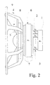
Figure 2 shows a side view of a loudspeaker structure according to an embodiment of the present invention using one additional mass attached by several elastic attachments effectively connected in parallel; -
Figure 3 depicts a side view of a loudspeaker structure according to an embodiment of the invention using a number of elastically attached additional masses effectively connected in parallel; -
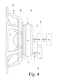
Figure 4 shows a side view of a loudspeaker structure according to an embodiment of the invention using a number of elastically attached additional masses effectively connected in a serial and a parallel fashion; and -
Figure 5 shows the parameters associated with the mechanical resonance and the corresponding electromechanical analogy of the embodiment ofFigure 1 . - Referring to
Fig. 1 . a dynamic loudspeaker element shown therein includes adriver unit 6 that, under actuation by an electromagnetic force, displaces aradiating element 5, typically a cone. Typically, the driver unit is composed of amagnet circuit 7 and a voice coil (not shown) moving inside the air gap in the magnet circuit. Conventionally, the voice coil is glued to the air-displacingcone 5. In this way, the loudspeaker element comprises the mass of an air displacing mechanism 8 (i.e., the cone and voice coil) and the mass of the stationary part 7 (the magnet circuit) and the frame structure of theloudspeaker element 4. - The cone-displacing driver unit comprising the magnet circuit and the voice coil moving in the air gap of the magnet circuit are attached to an external structure, typically the loudspeaker enclosure, by the
perimeter 9 of theloudspeaker element frame 4. Theframe 4 is typically made of a steel plate, plastic or die-cast metal, and it has a certain elasticity in the direction of the voice coil displacement axis. Also the front wall of the loudspeaker enclosure has some amount of elasticity that typically can be considered to add to the elasticity of theloudspeaker element frame 4. - As the loudspeaker operates, the electromagnetic force acts on the magnet circuit in the opposite direction to the force acting on the voice coil, thus causing the elasticity in the loudspeaker element frame and any elasticity in the mechanical attachment to the front wall of the enclosure to create one or more resonances with any mass mechanically coupled to either of these. Then, the vibrational energy has favourable conditions to become transmitted from the magnet circuit into enclosure walls, causing them to vibrate. This is not favourable, and this transmission of mechanical vibration energy creates acoustical radiation from the enclosure walls that sum up with the acoustical radiation emitted by the loudspeaker element. Hence, the acoustical output is no longer determined by the loudspeaker element alone as originally intended, and the quality of the audio output will deteriorate.
- For a typical loudspeaker, we can find an angular frequency w0 at which the mass of the magnet circuit displacing the voice coil and any stiffly connected part of the frame will resonate with the elasticity of the
frame 4. This mechanical resonance may be modelled as a lossy mass-spring system. - The present invention discloses a method for attaching additional masses to the
magnet circuit 7 such that theadditional masses 1 will resonate with themagnet circuit 7 at frequencies that can be chosen so as to, e.g., coincide with the resonant frequency w0 of the magnet circuit-frame system. Furthermore, these frequencies can be chosen to be any other frequencies at which the transmission of vibrational energy to the enclosure walls needs to be reduced. By a suitable choice of the amounts of additional masses and elasticities of their attachments, it is possible to control multiple resonances at multiple frequencies or in overlapping frequency bands. In this way, it is possible to adjust and control the efficiency and the frequency range of the mechanical vibration reduction. - The theoretical background of the invention is as follows.
- In the following discussion, reference is made to
Figure 5(a) depicting one elastically attached additional mass (mass m2) that forms a mass-spring system with the magnet circuit m1 and the stiffness of the element frame k1 and its losses c1. The displacement amplitude has a maximum at the resonant frequency of this system.Figure 5 depicts a system where a mass m2 with an elasticity k2 and loss factor c2 has been attached elastically to this system. - The resonant frequencies of this system of two coupled masses formed in this manner may be adjusted suitably by changing the elasticity k2 and loss factor c2 to minimize the displacement amplitude x1 at the mechanical resonant frequency of the magnet circuit mass m2-
- Newton's second law of motion

indicates that a system remains at rest if the sum of all forces acting on it are zero. The equations of motion [7] for the previous mass system, which is affected by the force of the voice coil F(t), can be written as

- Using an electromechanical analogy where the mechanical force F(t) appears as voltage v(t) and the motional velocity dx/dt appears as current i(t), the electromechanical analogy depicted in
Figure 5(b) can be formed. - Then, the behaviour of the two-mass mechanical system can be analyzed by either using the differential equations (Eq 2) and (Eq 3) or using the electrical analogy. In the following, the behaviour of this system is examined using the electromechanical analogy.
- Without an additional mass m2, the mass-spring system m1 formed by the above-described loudspeaker magnet circuit will oscillate with velocity v which depends on the angular velocity [6] as
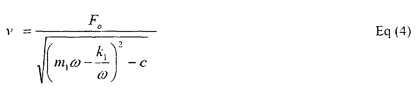
- When not employing the additional mass m2, the maximum of velocity occurs at a resonant frequency where the imaginary part of the denominator becomes zero, whereby the transfer of mechanical energy is the most efficient. The angular frequency of this resonance is

- Next, the change of the situation by the use of the additional mass m2 is examined. Analysis of the two-mass system of
Figure 5 using an electromechanical analogy shows that, through adjusting the resonant frequency of the additional mass, it is possible to reduce the displacement amplitude of the magnet circuit x1. This resonant frequency is determined by the mass m2 and the elasticity k2 of its attachment, and it is adjusted to be the same as the resonant frequency of the magnet circuit. - The ability of the additional mass to reduce the motional velocity depends on losses of the elastic attachment (component R2 in the electro-mechanical analogy). By adjusting losses to a right level after setting the resonant frequency to be right by using suitable materials and correct mechanical dimensioning for the elastic attachment, it is possible to reduce mechanical vibrations down to any level and obtain any desired level of vibration attenuation.
- The ability of the resonator created by the additional mass to absorb kinetic energy of the driver unit is characterized by the Q-value of the resonance system. It can be shown [6] that the Q-value is

-
Equation 6 shows that at the resonant frequency w0, the Q-value of the resonance and therefore, the ability to attenuate mechanical vibrations, depends on the amount of additional mass and the elasticity of its attachment to the magnet system. If the loss factor of the elastic attachment remains constant, the desired Q-value can be obtained by selecting the right amount of additional mass and right elasticity of the attaching spring. If the additional mass remains constant, the amount of losses of the attachment must be reduced as the frequency decreases. - Next, an example of determining the parameter values for a practicable embodiment of the present invention is discussed.
- The value of an additional mass according to the invention can be chosen, e.g., by measuring with the help of an acceleration transducer the resonant frequency of the mass-spring system formed by the magnet circuit and the loudspeaker element frame mounted in a loudspeaker enclosure. After the resonant frequency is known, to the
magnet circuit 7 is attached an additional mass having a weight approximately equal to the mass of the magnet circuit, and the measurement is repeated. By using the physical principles explained above, the correct value for the spring constant (represented by a correct loss factor and elasticity) and the mass then chosen. - An example of a system encountered in the practice of the art is represented by a loudspeaker element having a measured resonant angular frequency w0 of 3300 rad/s and the
magnet circuit 7 with a mass of 1.80 kg. In this case, theadditional mass 1 is attached by using a spring made of nitrile rubber having a sheet thickness of 4 mm and an area of 4.5 cm2. The elasticity of the material is 4.3 MN/m. The amount of additional mass in this case is chosen to be 0.4 kg. These selections produce effective reduction of vibrations. This example shows how properties of the attachment spring affect the amount of the required additional mass, and that the optimum may not be exactly the same mass as that creates the mass-resonance system in the loudspeaker, but that the mass does have the same order of magnitude. Furthermore, in some cases it is advantageous to divide the additional mass and its attachment spring into subcomponents. The mass and the elasticity may be varied according to the principles described above to reduce the effect of the mechanical resonance w0 down to a desired low level.
Claims (10)
- A method for attenuating mechanical resonances in a loudspeaker comprising resonant structures tuned with and attached to the loudspeaker,
the loudspeaker comprising a loudspeaker element and an enclosure associated with the loudspeaker element;
wherein the loudspeaker element comprises a frame (4) and a driver unit (6), the driver unit (6) comprising a magnet structure (7),
and wherein further the enclosure is mechanically connected to said driver unit (6) or said frame (4),
characterised in that
at least one additional mass (1) is is elastically (3) attached to the magnet structure (7) or to the parts of the frame (4) close to the magnet structure, said elastically (3) attached additional mass (1) having a resonant frequency falling at or within a range of the resonance of the driver unit (6), of said frame (4) and/or of the enclosure. - A method according to claim 1, characterized in that the total mass of said at least one additional mass (1) is selected such that the total mass is close to the mass of said magnet circuit (7), with said total additional mass being between about 0.1 to 10 times the mass of said magnet circuit.
- A method according to claim 1, characterized in that to said magnet structure (7) is elastically coupled said total additional mass comprising at least one additional mass and spring structures that are coupled to each other in parallel or serial fashion.
- A method according to claim 1, characterized in that said additional masses (1) are attached using an elastic material, such as- elastic rubber, plastic or other elastomer,- a metal spring- an air spring, or- any combination of these.
- A method according to claim 1, characterized in that elastic attachment (3) of said additional mass comprises one or more separate, equally elastic or differently elastic, partial springs that can be of the same or of different material, said partial springs being coupled to each another either in a serial or in parallel fashion.
- An arrangement for attenuating mechanical resonances in a loudspeaker,
the arrangement comprising a loudspeaker element and an enclosure associated with the loudspeaker element;
wherein the loudspeaker element comprises a frame (4) and a driver unit (6), the driver unit (6) comprising a magnet structure (7),
and wherein further the enclosure is mechanically connected to said driver unit (6) or said frame (4),
characterized in that
the arrangement comprises at least one additional mass (1) which is is elastically (3) attached to the magnet structure (7) or to the parts of the frame (4) close to the magnet structure, said elastically (3) attached additional mass (1) having a resonant frequency falling at or within a range of the resonance of the driver unit (6), of said frame (4) and/ or of the enclosure. - An arrangement according to claim 6, characterized in that said additional masses (1) having a mass that is of the same order of magnitude as the mass of said magnet circuit (7), where the total mass of said additional masses being 0.1 to 10 times the mass of said magnet circuit (7).
- An arrangement according to patent claim 6, characterized in that said additional masses (1) are attached using an elastic material, such as- elastic rubber, plastic or other elastomer,- a metal spring- an air spring, or- any combination of these.
- An arrangement according to claim 6, characterized in that said elastic attachment (3) of said additional mass comprises one or more separate, equally elastic or differently elastic, partial springs that can be of the same or of different material, said partial springs being coupled to each another either in a serial or in parallel fashion.
- An arrangement according to claim 6, characterized in that said additional masses (6) are made from a solid material.
Applications Claiming Priority (2)
| Application Number | Priority Date | Filing Date | Title |
|---|---|---|---|
| FI974217 | 1997-11-12 | ||
| FI974217A FI104302B (en) | 1997-11-12 | 1997-11-12 | Method and apparatus for attenuating mechanical resonances of a speaker |
Publications (3)
| Publication Number | Publication Date |
|---|---|
| EP0917396A2 EP0917396A2 (en) | 1999-05-19 |
| EP0917396A3 EP0917396A3 (en) | 2004-12-01 |
| EP0917396B1 true EP0917396B1 (en) | 2010-08-25 |
Family
ID=8549928
Family Applications (1)
| Application Number | Title | Priority Date | Filing Date |
|---|---|---|---|
| EP98660121A Expired - Lifetime EP0917396B1 (en) | 1997-11-12 | 1998-11-11 | Method and arrangement for attenuating mechanical resonance in a loudspeaker |
Country Status (5)
| Country | Link |
|---|---|
| US (1) | US6373956B1 (en) |
| EP (1) | EP0917396B1 (en) |
| JP (1) | JP4615638B2 (en) |
| DE (1) | DE69841856D1 (en) |
| FI (1) | FI104302B (en) |
Families Citing this family (19)
| Publication number | Priority date | Publication date | Assignee | Title |
|---|---|---|---|---|
| GB2350965B (en) * | 1999-06-10 | 2001-08-22 | Stefan Gamble | Loudspeaker cabinet and microphone housing internal damping system |
| JP3484143B2 (en) * | 1999-12-02 | 2004-01-06 | 株式会社タイムドメイン | Speaker device |
| JP2001300422A (en) * | 2000-04-21 | 2001-10-30 | Citizen Electronics Co Ltd | Multifunctional converter and its driving method |
| JP4153156B2 (en) | 2000-11-10 | 2008-09-17 | 富士通テン株式会社 | Speaker device |
| JP4144197B2 (en) * | 2001-07-04 | 2008-09-03 | 新科實業有限公司 | Vibration suppression mechanism and head gimbal assembly with vibration suppression mechanism |
| US7551749B2 (en) | 2002-08-23 | 2009-06-23 | Bose Corporation | Baffle vibration reducing |
| JPWO2005004535A1 (en) * | 2003-07-02 | 2006-11-24 | シチズン電子株式会社 | Panel type speaker |
| KR20050031778A (en) * | 2003-09-30 | 2005-04-06 | 삼성광주전자 주식회사 | Device for reducing vibration and hermetic compressor having the same |
| EP1630788B1 (en) * | 2004-08-26 | 2012-04-18 | Airbus Operations GmbH | Device and method for reducing sound of a noise source in narrow frequency ranges |
| US7844068B1 (en) * | 2005-01-05 | 2010-11-30 | Linear Corporation | Wall mounted speaker system, apparatus and method |
| US7828113B1 (en) | 2007-04-02 | 2010-11-09 | Kim Dao | Methods and apparatus for controlling vibration of enclosures, particularly loudspeaker enclosures |
| US8180076B2 (en) * | 2008-07-31 | 2012-05-15 | Bose Corporation | System and method for reducing baffle vibration |
| EP2514217B1 (en) | 2009-12-17 | 2015-04-22 | Genelec OY | Drive unit mounting arrangement and loudspeaker |
| GB2488758A (en) | 2011-03-02 | 2012-09-12 | Gp Acoustics Uk Ltd | Bass reflex loudspeaker has acoustic leakage in walls of port duct |
| GB2491108B (en) | 2011-05-18 | 2014-06-04 | Gp Acoustics Uk Ltd | Loudspeaker |
| US12300207B2 (en) * | 2022-06-24 | 2025-05-13 | Toyota Motor Engineering & Manufacturing North America, Inc. | Flexural wave absorbers for wave and vibration isolation in thin walled structures |
| WO2024030576A1 (en) * | 2022-08-04 | 2024-02-08 | Barefoot Sound, Llc | Method and apparatus for reducing reaction forces in loudspeakers |
| CN117241188A (en) * | 2023-09-28 | 2023-12-15 | 瑞声科技(南京)有限公司 | a speaker |
| WO2025065587A1 (en) * | 2023-09-28 | 2025-04-03 | 瑞声科技(南京)有限公司 | Loudspeaker |
Family Cites Families (11)
| Publication number | Priority date | Publication date | Assignee | Title |
|---|---|---|---|---|
| JPS606157B2 (en) * | 1977-07-25 | 1985-02-15 | ソニー株式会社 | speaker |
| DE3037227A1 (en) | 1980-10-02 | 1982-04-29 | Alfred 2800 Bremen Rinkowski | Loudspeaker assembly with resonator - has cylindrical resonator body between coil actuator and membrane |
| US4598178A (en) | 1983-12-16 | 1986-07-01 | Rollins William L | Means for critically damping a dynamic loudspeaker |
| JPS6121699A (en) * | 1984-07-10 | 1986-01-30 | Pioneer Electronic Corp | Electric vibrating transducer |
| AU580794B2 (en) * | 1984-09-03 | 1989-02-02 | Sanden Corporation | Dynamic transducer device |
| GB2192041B (en) * | 1986-06-24 | 1990-10-10 | Fokker Bv | Vibration absorber with controllable resonance frequency |
| US4710656A (en) * | 1986-12-03 | 1987-12-01 | Studer Philip A | Spring neutralized magnetic vibration isolator |
| FR2674092B3 (en) * | 1991-03-15 | 1993-02-05 | Focal Sa | PERFECTED SPEAKER. |
| BE1004807A3 (en) * | 1991-03-19 | 1993-02-02 | Schellekens Ivan | Reproducers mechanical inter without distortion. |
| JP3144230B2 (en) * | 1994-09-01 | 2001-03-12 | 松下電器産業株式会社 | Bass reproduction speaker |
| US6195442B1 (en) * | 1999-08-27 | 2001-02-27 | The United States Of America As Represented By The Secretary Of The Air Force | Passive vibroacoustic attenuator for structural acoustic control |
-
1997
- 1997-11-12 FI FI974217A patent/FI104302B/en not_active IP Right Cessation
-
1998
- 1998-11-11 EP EP98660121A patent/EP0917396B1/en not_active Expired - Lifetime
- 1998-11-11 DE DE69841856T patent/DE69841856D1/en not_active Expired - Lifetime
- 1998-11-12 JP JP32243998A patent/JP4615638B2/en not_active Expired - Lifetime
- 1998-11-12 US US09/190,175 patent/US6373956B1/en not_active Expired - Lifetime
Also Published As
| Publication number | Publication date |
|---|---|
| EP0917396A3 (en) | 2004-12-01 |
| US6373956B1 (en) | 2002-04-16 |
| JPH11234794A (en) | 1999-08-27 |
| JP4615638B2 (en) | 2011-01-19 |
| FI974217A0 (en) | 1997-11-12 |
| FI974217A7 (en) | 1999-05-13 |
| FI104302B1 (en) | 1999-12-15 |
| EP0917396A2 (en) | 1999-05-19 |
| FI104302B (en) | 1999-12-15 |
| DE69841856D1 (en) | 2010-10-07 |
Similar Documents
| Publication | Publication Date | Title |
|---|---|---|
| US6373956B1 (en) | Method and arrangement for attenuating mechanical resonance in a loudspeaker | |
| AU725754B2 (en) | Loudspeakers | |
| US4951930A (en) | Insulator for use in automotive suspension or the like | |
| CN1653849B (en) | converter | |
| JP3192100B2 (en) | Microphone | |
| KR20010043227A (en) | Vibration actuator having magnetic circuit elastically supported by a spiral damper with increased compliance | |
| US20070263886A1 (en) | Transducer | |
| US7636447B2 (en) | Acoustic bracket system | |
| CN101611438A (en) | Sound insulation board and sound insulation device equipped therewith | |
| US6279679B1 (en) | Selectively tuned vibration absorber | |
| EP1744302A2 (en) | Vibration excited sound absorber with dynamic tuning | |
| EP1491405A1 (en) | Speaker apparatus to be mounted on a vehicle | |
| US6286782B1 (en) | Apparatus and method for reducing vibrations of a structure particularly a helicopter | |
| EP1410680B1 (en) | Planar loudspeaker | |
| US5691516A (en) | Tunable vibration absorber | |
| US7062051B2 (en) | Acoustic device | |
| CN114339536B (en) | Passive radiator unit and speaker system including the same | |
| JP2004028125A (en) | Dynamic damper | |
| JP3139125B2 (en) | Engine damping structure | |
| CN100397952C (en) | Method for distributing mode resonance frequency of plate of sound device | |
| EP4316677A1 (en) | Structural body, vibrating device, and sensory acoustic apparatus | |
| JP2000291711A (en) | Buffer washer and buffering structure | |
| JPS643436B2 (en) | ||
| JP2026052947A (en) | Vehicle body structure | |
| JP2002349632A (en) | Engine mounting device |
Legal Events
| Date | Code | Title | Description |
|---|---|---|---|
| PUAI | Public reference made under article 153(3) epc to a published international application that has entered the european phase |
Free format text: ORIGINAL CODE: 0009012 |
|
| AK | Designated contracting states |
Kind code of ref document: A2 Designated state(s): AT BE CH CY DE DK ES FI FR GB GR IE IT LI LU MC NL PT SE |
|
| AX | Request for extension of the european patent |
Free format text: AL;LT;LV;MK;RO;SI |
|
| PUAL | Search report despatched |
Free format text: ORIGINAL CODE: 0009013 |
|
| AK | Designated contracting states |
Kind code of ref document: A3 Designated state(s): AT BE CH CY DE DK ES FI FR GB GR IE IT LI LU MC NL PT SE |
|
| AX | Request for extension of the european patent |
Extension state: AL LT LV MK RO SI |
|
| RIC1 | Information provided on ipc code assigned before grant |
Ipc: 7H 04R 1/28 B Ipc: 7H 04R 3/00 A |
|
| 17P | Request for examination filed |
Effective date: 20050120 |
|
| AKX | Designation fees paid |
Designated state(s): DE FR GB IT |
|
| 17Q | First examination report despatched |
Effective date: 20060803 |
|
| GRAP | Despatch of communication of intention to grant a patent |
Free format text: ORIGINAL CODE: EPIDOSNIGR1 |
|
| GRAS | Grant fee paid |
Free format text: ORIGINAL CODE: EPIDOSNIGR3 |
|
| GRAA | (expected) grant |
Free format text: ORIGINAL CODE: 0009210 |
|
| AK | Designated contracting states |
Kind code of ref document: B1 Designated state(s): DE FR GB IT |
|
| REG | Reference to a national code |
Ref country code: GB Ref legal event code: FG4D |
|
| REF | Corresponds to: |
Ref document number: 69841856 Country of ref document: DE Date of ref document: 20101007 Kind code of ref document: P |
|
| PLBE | No opposition filed within time limit |
Free format text: ORIGINAL CODE: 0009261 |
|
| STAA | Information on the status of an ep patent application or granted ep patent |
Free format text: STATUS: NO OPPOSITION FILED WITHIN TIME LIMIT |
|
| 26N | No opposition filed |
Effective date: 20110526 |
|
| REG | Reference to a national code |
Ref country code: DE Ref legal event code: R097 Ref document number: 69841856 Country of ref document: DE Effective date: 20110526 |
|
| REG | Reference to a national code |
Ref country code: FR Ref legal event code: PLFP Year of fee payment: 18 |
|
| REG | Reference to a national code |
Ref country code: FR Ref legal event code: PLFP Year of fee payment: 19 |
|
| REG | Reference to a national code |
Ref country code: FR Ref legal event code: PLFP Year of fee payment: 20 |
|
| PGFP | Annual fee paid to national office [announced via postgrant information from national office to epo] |
Ref country code: FR Payment date: 20171121 Year of fee payment: 20 Ref country code: DE Payment date: 20171121 Year of fee payment: 20 |
|
| PGFP | Annual fee paid to national office [announced via postgrant information from national office to epo] |
Ref country code: GB Payment date: 20171123 Year of fee payment: 20 Ref country code: IT Payment date: 20171124 Year of fee payment: 20 |
|
| REG | Reference to a national code |
Ref country code: DE Ref legal event code: R071 Ref document number: 69841856 Country of ref document: DE |
|
| REG | Reference to a national code |
Ref country code: GB Ref legal event code: PE20 Expiry date: 20181110 |
|
| PG25 | Lapsed in a contracting state [announced via postgrant information from national office to epo] |
Ref country code: GB Free format text: LAPSE BECAUSE OF EXPIRATION OF PROTECTION Effective date: 20181110 |