EP0917176B1 - Straddle bearing assembly for a rotating anode X-ray tube - Google Patents
Straddle bearing assembly for a rotating anode X-ray tube Download PDFInfo
- Publication number
- EP0917176B1 EP0917176B1 EP98307607A EP98307607A EP0917176B1 EP 0917176 B1 EP0917176 B1 EP 0917176B1 EP 98307607 A EP98307607 A EP 98307607A EP 98307607 A EP98307607 A EP 98307607A EP 0917176 B1 EP0917176 B1 EP 0917176B1
- Authority
- EP
- European Patent Office
- Prior art keywords
- bearing
- assembly
- anode
- elongated portion
- straddle
- Prior art date
- Legal status (The legal status is an assumption and is not a legal conclusion. Google has not performed a legal analysis and makes no representation as to the accuracy of the status listed.)
- Expired - Lifetime
Links
Images


Classifications
-
- H—ELECTRICITY
- H01—ELECTRIC ELEMENTS
- H01J—ELECTRIC DISCHARGE TUBES OR DISCHARGE LAMPS
- H01J35/00—X-ray tubes
- H01J35/02—Details
- H01J35/04—Electrodes ; Mutual position thereof; Constructional adaptations therefor
- H01J35/08—Anodes; Anti cathodes
- H01J35/10—Rotary anodes; Arrangements for rotating anodes; Cooling rotary anodes
- H01J35/101—Arrangements for rotating anodes, e.g. supporting means, means for greasing, means for sealing the axle or means for shielding or protecting the driving
- H01J35/1017—Bearings for rotating anodes
- H01J35/1024—Rolling bearings
-
- H—ELECTRICITY
- H01—ELECTRIC ELEMENTS
- H01J—ELECTRIC DISCHARGE TUBES OR DISCHARGE LAMPS
- H01J2235/00—X-ray tubes
- H01J2235/10—Drive means for anode (target) substrate
- H01J2235/1046—Bearings and bearing contact surfaces
Definitions
- the present invention relates to straddle bearing assemblies, especially in relation to x-ray tube bearing assemblies and will be described with particular reference thereto. It is to be appreciated, however, that the invention may also find application in conjunction with bearing assemblies in other applications.
- x-radiation includes the form of radiography, in which a still shadow image of the patient is produced on x-ray film, fluoroscopy, in which a visible real time shadow light image is produced by low intensity x-rays impinging on a fluorescent screen after passing through the patient, and computed tomography (CT) in which complete patient images are electrically reconstructed from x-rays produced by a high powered x-ray tube rotated about a patient's body.
- CT computed tomography
- a typical x-ray tube electrons are generated from a filament coil heated to thermionic emission.
- the electrons are accelerated as a beam from a cathode through an evacuated chamber defined by a glass envelope, toward an anode.
- An x-ray tube assembly is contained in a housing which includes a window transmissive to x-rays, such that radiation from the anode passes through the window toward a subject undergoing examination or treatment.
- a filament is a coil of wire which is electrically energized so that electrons are thermionically emitted from the filament.
- the electrons are accelerated toward the anode due to a DC electrical potential difference between the cathode and the anode.
- this electrical potential difference is of the order of 150,000 volts, ( ⁇ 75,000 volts to ground) necessitating significant electrical insulation between the various tube components.
- a rotating anode configuration In order to distribute the thermal loading and reduce anode temperature a rotating anode configuration has been adopted for many applications.
- an electron beam is focussed near a peripheral edge of the anode disk at a focal spot.
- a different portion of a circular path around the peripheral edge of the anode passes through the focal spot where x-rays are generated.
- Each portion along the circular path is heated to a very high temperature during the generation of x-rays and cooled as it is rotated before returning for the generation of x-rays.
- the diameter and the mass of the rotating anode continues to grow.
- a gantry holding the x-ray tube is rotated around a patient's body in order to obtain complete images of the patient.
- typical CT scanners revolve the x-ray tube around the patient's body at a rate of between 60-120 rotations-per-minute (RPM).
- RPM rotations-per-minute
- the anode needs to be properly supported and stabilized from the effects of its own rotation and, in some instances, from centrifugal forces created by rotation of the x-ray tube about a patient's body.
- the anode is mounted on a stem and rotated by a motor.
- the anode, stem and other components rotated by the motor are part of a rotating assembly which is supported by a bearing assembly.
- the bearing assemblies found in most x-ray tubes today utilize either a cantilevered bearing arrangement or a straddle bearing arrangement. In a cantilevered bearing arrangement, all bearings are located on the same side of the rotating assembly's centre of mass. In a straddle bearing arrangement, bearings are located on both sides of the rotating assembly's centre of mass.
- One drawback to using the cantilevered bearing arrangement is that a bearing closest to the anode experiences a much greater load than the bearing(s) further from the anode.
- the bearing closest to the anode therefore has greater contact stresses which deleteriously effects the life of the entire bearing assembly and thus the x-ray tube life. If the size of the bearings closest to the anode were increased to distribute the contact stresses, the internal surface speeds of this bearing would increase and the bearing life would decrease due to a faster wear rate. Thus, the bearing closest to the anode would still typically fail first.
- straddle bearing arrangement In an effort to more equally distribute the load of the rotating assembly among the bearings, the straddle bearing arrangement was developed.
- Typical straddle bearing arrangements employ a large bearing-to-bearing distance.
- the bearing-to-bearing distance is sometimes referred to as a straddle or wheelbase.
- the large wheelbase is required to thermally insulate the bearings from the anode which is typically very hot.
- the anode is often in the range of 1200 degrees C. Heat from the anode is thermally conducted to the bearings through the predominantly metal bearing assembly.
- the other bearing(s) can be placed at an appropriate distance further away from the bearing closest to the anode. This is possible since the thermally conductive path to the other bearings is always further than the thermally conductive path to the bearing closest to the anode. Therefore, thermal insulation does not require the large wheelbase in a cantilevered bearing arrangement that it does in a conventional straddle bearing arrangement.
- Thermal compensation becomes much more difficult.
- Thermal compensation relates to the accommodations made in the bearing assembly in both the radial and axial directions to account for changes in bearing tolerances caused by temperature variances.
- designing for thermal compensation in a straddle bearing assembly is extremely difficult given the large wheelbases dictated by the need to thermally insulate the bearings.
- One common technique used in both cantilevered and straddle bearing arrangements to ensure predictability in the effect temperature swings have on the bearing assembly is to only allow thermal movement in the bearing assembly to occur in one direction as opposed to compensating for thermal movement symmetrically about the bearing. This is typically done by securing in place at least one end of each component of the bearing assembly such that thermal shrinkage and growth occurs in a known direction at the opposite end. As a consequence, as components coupled to the bearing assembly expand and contract due to temperature variances, the anode also moves thereby creating changes to the focal spot. More specifically, as most conventional bearing assemblies restrict thermal expansion and contraction to occur in a direction substantially parallel with an axis of rotation of the anode, thermal movements typically cause the focal spot to change is size.
- Such change in size to the focal spot is undesirable as it causes blurring to images taken from the x-rays radiating from the anode. Further, such thermal expansion and contraction also causes undesired movement of the focal spot with respect to x-ray detectors outside of the x-ray tube which may additionally deleteriously effect the quality of the images taken.
- Typical implementations of straddle bearing designs also employ an outer bearing race rotation.
- Inner bearing race rotation is not available in straddle bearing designs as aligning bearings on opposite sides of the anode to handle such inner bearing race rotation has not been achievable. Aligning the bearings is difficult primarily because outer races for each bearing must be independently positioned on opposite sides of the anode in conventional straddle bearing designs and slight deviations from perfectly symmetrically placement of the outer bearings causes the anode supported by the bearing assembly to wobble during operation.
- outer bearing race rotation increases surface speeds in the bearing and therefore increases the wear on the bearings. Further, because bearings in a straddle bearing assembly are physically located on both sides of the anode, difficulties arise in electrically isolating the bearings from high voltages.
- the cathode would be at a -75,000 volt potential while the anode would be at a +75,000 volt potential.
- the bearing assembly is coupled to the anode assembly, the bearings are at the anode voltage potential.
- at least one of the bearings is in close proximity to the cathode and therefor needs to be electrically insulated from the cathode voltage potentials in order to avoid undesirous arcing from occurring.
- x-ray tube having a straddle bearing assembly typically implement a single ended configuration where the anode is at ground potential and the cathode is at -150,000 volts. Unfortunately this makes it difficult for such x-ray tubes to be used in a retrofit manner since most x-ray tube generators are configured to handle only a bi-polar topology.
- JP-A-03/074033 describes a rotary anode X-ray tube wherein the disc is connected to a shaft which shaft is supported by two bearings. The bearings are arranged at about the same height as the contour of the anode ring. A metal cylinder is provided to support the bearings and a cooling part is provided in the lower part of the metal cylinder, i.e. in a region below the anode disc.
- US 3,758,801 describes a rotating anode X-ray tube wherein a cylindrical anode is mounted on a shaft, which shaft is supported by two space bearings.
- JP-A-62/200642 shows a rotary anode X-ray tube with a disc type anode at one end of the bearing shaft. At the other end of the bearing shaft, a counter weight is provided in form of an adjusting ring.
- US 5,303,280 describes a large diameter anode X-ray tube with reinforced support. An anode disc is mounted on a rotating shaft held in the manner of cantilever bearing arrangement.
- US 3,790,836 also describes a rotating anode disc of the cantilever bearing arrangement type.
- the present invention provides a straddle bearing assembly for an X-ray tube and a method of assembling an X-ray tube as defined in the appended claims.
- a CT scanner 10 includes a radiation source 12, such as an x-ray tube, for projecting a fan beam of radiation through an examination region or scan circle 14.
- the x-ray tube 12 is mounted on a rotatable gantry 16 to rotate the fan beam of radiation around the examination region 14.
- a collimator and shutter assembly 18 collimates the radiation to one or more planer beams and selectively gates the beams on and off.
- Radiation detectors 20 are mounted peripherally around the examination region 14 and detect the radiation for processing.
- a motor 24 provides motive power for rotating the gantry 16 continuously around the examination region 14.
- a patient support 30 supports a patient subject in a reclined position.
- the patient support 30 is advanced through the examination region 14, preferably at a constant velocity.
- the x-ray tube 12 is rotated about the patient support 30 to ensure a complete set of information is available for reconstruction.
- the detectors 20 are coupled to view reconstruction circuitry 30.
- the view reconstruction circuitry 30 stores and processes data received from the detectors 20 and maintains selected slice and volumetric images of the patient.
- a video processor 35 retrieves image information from the view reconstruction circuitry 30 and formats the image data into appropriate formats for display on video monitor 40 or the like.
- the x-ray tube 12 of the present invention includes a housing 50 filled with a heat transfer and electrically insulating fluid such as oil.
- a heat transfer and electrically insulating fluid such as oil.
- Supported within the housing 50 is an envelope 52, typically comprised of glass or metal, within which an evacuated chamber or vacuum is defined.
- an anode assembly 55 and a cathode assembly 59 Disposed within the envelope 52 is an anode assembly 55 and a cathode assembly 59.
- the anode assembly 55 shown is comprised of a molybdenum alloy front plate 56 and a graphite back plate 57.
- the front plate 56 of the anode assembly includes an anode surface 55a facing a cathode focussing cup 60 of the cathode assembly 55.
- a portion of the anode surface 55a closest a focal spot 63 is made of a tungsten and rhenium composite in order to aid in the production of x-rays.
- the front plate 56 of the anode assembly 55 includes an elongated neck portion 58 as discussed in more detail below. It will be appreciated, however, that other single or multiple piece anode configurations made of any suitable substances could alternatively be used.
- a cathode filament 62 mounted to the cathode focussing cup 60 is energized to emit electrons which are accelerated to the anode assembly 55 to produce x-radiation for diagnostic imaging, therapy treatment and the like.
- the cathode focussing cup 60 serves to focus electrons emitted from the cathode filament 62 to the focal spot 63 on the anode surface 55a.
- the electrons are emitted from the cathode filament 62 and accelerated toward the anode assembly 55 due to a very large DC electrical potential difference between the cathode focussing cup 60 and the anode assembly 55.
- the cathode focussing cup 60 is at an electrical potential of -75,000 volts with respect to ground, and the anode assembly 55 is at an electrical potential of +75,000 volts with respect to ground thereby providing a bipolar configuration having a total electrical potential difference of 150,000 volts.
- Impact of the electrons from the cathode filament 62 onto the anode surface 55a typically causes the anode assembly 55 to be heated to a range of between 1100°-1400° C.
- the x-ray tube anode assembly 55 is mounted for rotation about an axis 65 via a straddle bearing assembly shown generally at 68. More specifically, the front plate 56 of the anode assembly 55 is rigidly coupled to shaft 70 and rotor 75.
- the rotor 75 includes a rotor body 77 which is coupled to induction motor 80 for rotating the shaft 70 and anode assembly 55 about the axis 65. All of the components rotated by the motor 80, including the rotor 75, rotor body 77, shaft 70 and anode assembly 55 are hereinafter referred to as rotating assembly 79.
- the straddle bearing assembly 68 supports the load of the rotating assembly 79 during rotation.
- the load of the rotating assembly 79 includes the weight of all of the components of the rotating assembly 79 including the weight of the anode assembly 55.
- the shaft 70 defines a pair of inner races 82a, 82b.
- a plurality of ball or other bearing members 90a are received between the inner bearing race 82a and an outer bearing race 92a defined by an outer bearing member 94a.
- a plurality of ball or other bearing members 90b are received between the inner bearing race 82b and an outer bearing race 92b defined by an outer bearing member 94b.
- the bearings 90a, 90b provide for rotation of the anode assembly 55 about the axis 65.
- Each bearing 90a and 90b is situated on an opposite side of the centre of mass of the rotating assembly 79 along the axis 65.
- the centre of mass of the rotating assembly 79 is shown along dashed line C ( Fig. 2 ).
- a bearing housing 100 includes a first elongated portion 101, a second elongated portion 102, a base portion 103, and U shaped bend 104. Both the first elongated portion 101 and the second elongated portion 102 are substantially parallel to the axis 65 and pass through the centre of mass C of the rotating assembly 79.
- the first elongated portion 101 and second elongated portion 102 of the bearing housing 100 which are coupled together at the U shaped bend 104 define a cooling duct 119.
- the bearing housing 100 of the present embodiment is made of copper, however, it will be appreciated that other suitable materials could alternatively be used.
- Each outer bearing member 94a and 94b is cylindrical in shape and spaced apart from one another by a spacer 106.
- the outer bearing members 94a and 94b and spacer 106 are positioned within a cavity 107 defined by the elongated portion 102 and base portion 103 of the bearing housing 100.
- a retaining spring 108 is positioned within the cavity 107 adjacent the base portion 103 of the bearing housing 100 and a snap ring 105 is rigidly secured to the elongated portion 102 of the bearing housing 100 at an opposite end of the cavity 107.
- the retaining spring 108 and the snap ring 105 serve to frictionally sandwich and secure the outer bearing members 94a and 94b and spacer 106 within the cavity 107.
- the outer bearing members 94a and 94b and the spacer 106 are made of copper although other suitable materials could alternatively be used.
- the x-ray tube 12 further includes an oil nozzle 115.
- the nozzle 115 serves to pump oil in a direction indicated by arrows A1 through the cooling duct 119.
- the oil pumped by the nozzle 115 is obtained from a region R1 between the envelope 52 and x-ray tube housing 50.
- the oil travels through the cooling duct 119 along a path adjacent the elongated portion 102 of the bearing housing 100, the oil serves to remove heat from the outer bearing members 94a and 94b thereby reducing thermal stress placed on bearings 90a and 90b.
- the oil serves to absorb heat radiated from the front plate 56 and back plate 57 of the anode assembly 55.
- the oil flowing thorough the cooling duct 119 is typically flowing at a rate of approximately three gallons per minute although this rate may optionally be varied to obtain desired cooling effects.
- the nozzle 115 may optionally reverse the flow of oil through the cooling duct 119.
- heat from the anode assembly 55 is primarily passed to the bearings 90a, 90b via a thermally conductive path shown by arrowed paths 120 and 125.
- arrowed path 120 begins at a peripheral edge of the anode assembly 55 which comes in contact with the electrons dissipated from the cathode filament 62 and travels along the elongated neck portion 58 of the anode assembly 55 to the shaft 70.
- Arrowed path 125 runs substantially parallel with the axis 65 of rotation of the shaft 70 and has two end indicators. The first end indicator is shown at I1 and indicates an end of a full thermally conductive path to the bearing 90b from the peripheral edge of the anode assembly 55.
- the second end indicator is shown at I2 and indicates an end of a full thermally conductive path to the bearing 90a from the peripheral edge of the anode assembly 55.
- thermally conductive path and derivations thereof includes a path by way of which heat is transferred between two points other than a path through a vacuum, air, or gas.
- the full thermally conductive path to the bearing 90a includes the full thermally conductive path to the bearing 90b.
- the bearing 90a will be at a cooler temperature then the bearing 90b. Therefore, once the bearing 90b is placed a sufficient distance along the thermally conductive path from the peripheral edge of the anode assembly 55 such that the heat dissipated to the bearing 90b in the region around I1 does not place undue temperature stress on the bearing 90b, bearing 90a is likewise protected.
- the thermally conductive path to the bearing 90b includes more area for heat from the anode assembly 55 to be dissipated via oil flowing through the cooling duct 119 thereby reducing thermal stresses placed on the bearings 90a, 90b. More specifically, as heat from the peripheral edge of the anode assembly 55 travels along the elongated neck portion 58, heat radiated from the elongated neck portion 58 may be absorbed through the elongated portion 101 of the bearing housing 100 into the oil flowing through the cooling duct 119.
- the present invention is able to reduce the thermal stress placed on the bearings 90a and 90b thereby extending their operational life and thus the operational life of the x-ray tube 12.
- the wheelbase of the straddle bearing assembly 68 of the present invention is shown to be a distance of D 1 + D2 where D1 represents the distance between the bearing 90a and the centre of mass C of the rotating assembly 79 and where D2 represents the distance between the bearing 90b and the centre of mass C of the rotating assembly 79.
- the distance D1 and D2 are substantially equal thereby providing that the bearing 90a and the bearing 90b each support a substantially equal load of the rotating assembly 79.
- the full thermally conductive path to the bearing 90a includes the full thermally conductive path to the bearing 90b
- the wheelbase D1+D2 for bearings of a desired size, temperature and wear rate is significantly less than a wheelbase needed in a conventional straddle bearing assembly having bearings of similar characteristics.
- the wheelbase of conventional straddle bearing assemblies were often very large since thermal insulation from the anode assembly required the bearings to be placed along thermally conductive paths from the anode assembly that were opposite in direction from one another. Since the thermally conductive path for bearings 90a, 90b are not opposite in direction from one another in the present invention, such large wheelbases are not necessary.
- the wheelbase D1+D2 of the present invention is often less than 50% of the wheelbase needed in a conventional straddle bearing assembly having bearings of similar characteristics. This, in turn, allows for easy thermal compensation of the bearing assembly 68. As discussed above in the background section, large wheelbases are undesirable since compensating the bearing assembly for thermal expansion and contraction is difficult with larger wheelbases. As the present invention does not require such a large wheel base to obtain similar wear rates on bearings of comparable size and temperature, design difficulties associated with needing to thermally compensate for large temperature variances is avoided.
- the present embodiment shows the distance D1 and D2 between each bearing 90a, 90b, respectively, to be substantially equal in length
- the present invention allows for the distances D1 and D2 to be independently varied to desired lengths.
- the bearing 90a may be moved into a position closer to the centre of mass C of the rotating assembly 79 than the bearing 90b.
- distance D1 is shorter than distance D2.
- the bearing 90a supports a larger load of the rotating assembly 79 than the bearing 90b. This in turn offsets some or all of the effects the higher temperature stress has on the bearing 90b thereby providing a bearing assembly 68 in which both bearings 90a and 90b wear at approximately the same rate so that the life of the bearing assembly 68 is maximized.
- the bearings 90a and 90b are both on opposite sides of the centre of mass C of the rotating assembly 79, the bearings 90a and 90b are both also positioned on a same side of the anode assembly 55 relative the front plate 56. More specifically, as shown in Fig. 2 the front plate 56 of the anode assembly 55 follows along the elongated neck portion 58 and through a junction between the anode assembly 55 and the rotor 75. Thus, the bearings 90a and 90b are both positioned on a side of the front plate 56 of the anode assembly 55 opposite the side facing the cathode cup 60.
- the x-ray tube 12 may be configured with a bipolar arrangement since neither of the bearings 90a, 90b of the straddle bearing assembly 68 are directly exposed to the electric field of the cathode assembly 55 and therefore additional electrical insulation with respect to the cathode assembly 55 is not necessary.
- the motor 80 ( Fig. 2 ) rotates the rotor 75 which is rigidly attached to the anode assembly 55 .
- the anode assembly 55 is in turn rigidly attached to the shaft 70.
- the anode assembly 55 and shaft 70 are both rotated about the axis 65 while supported by the straddle bearing assembly 68.
- the bearings 90a, 90b of the present invention are both rotated via an inner bearing race rotation by shaft 70.
- Inner bearing race rotation involves rotating the inner races 82a, 82b ( Fig. 3 ) of the bearing assembly 68 while maintaining the outer races 92a, 92b in a stationary position.
- inner races 82a, 82b are defined by the shaft 70, inner bearing race rotation is achieved in the present embodiment by rotating the shaft 70.
- Inner bearing race rotation minimizes surface speeds leading to wear on the bearings 90a, 90b since a single rotation of the anode assembly 55 causes less movement with respect to the bearings 90a, 90b than outer bearing race rotation. More specifically, with inner bearing race rotation, a single rotation of the anode assembly 55 only causes rotation of the bearings 90a, 90b to an extent of movement of the inner races 82a, 82b which is defined by a circumference of the shaft 70. With outer bearing race rotation, a single rotation of the anode assembly 55 causes rotation of the bearings 90a, 90b to an extent of movement of the outer races 92a, 92b which is defined by a circumference of the outer bearing members 94a, 94b.
- Inner bearing race rotation is available in the present invention given the relationship between the straddle bearing assembly 68 and the anode assembly 55. More specifically, the straddle bearing assembly 68 provides both bearings 90a and 90b of the present invention to be located on the same side of the anode assembly 55. As such, symmetrically aligning the outer races 92a, 92b to handle inner race rotation without wobble is relatively easy since both outer bearing members 94a and 94b are precisely positioned within the cavity 107 predefined by the bearing housing 100. By comparison, in a conventional straddle bearing assembly each bearing is placed on an opposite side of the anode assembly.
- the shaft 70 thermally expands in a direction indicated by arrow A2 ( Fig. 2 ). Thermal expansion of the shaft 70 in an opposite direction of arrow A2 is not possible given that an opposite end of the shaft 70 closest to the bearing 90a is situated against the base portion 103 of the bearing housing 100 which is fixed in place. As the anode assembly 55 is rigidly coupled to the shaft 70, thermal expansion of the shaft 70 also causes the front plate 56 of the anode assembly 55 to move in the direction of arrow A2. However, the present invention provides a counterbalance for the thermal expansion in the shaft 70.
- the front plate 56 of the anode assembly 55 is caused to move in a direction opposite the direction of arrow A2.
- Thermal expansion of the elongated neck portion 58 causes expansion in the direction opposite the arrow A2 since the front plate 56 and back plate 57 of the anode assembly 55 are not fixed or restrained from movement by any component of the x-ray tube 12 in this direction.
- the positioning of the front plate 56 of the anode assembly 55 remains substantially stationary during temperature changes in the x-ray tube.
- the focal spot 63 on the anode surface 55a also remains a substantially constant size regardless of the heating and cooling effects of the anode assembly 55 and bearing assembly 68. Further, the focal spot 63 does not substantially move with respect to x-ray detectors (not shown) outside of the x-ray tube 12.
- the bearing housing 100 of the x-ray tube 12 is made of sections which are glass and sections which are copper to help aid in cooling the anode assembly 55. More specifically, as shown in figure 4 , the elongated portion 101 is made of glass and the elongated portion 102 and base portion 103 are made of copper. The elongated portion 101 and the elongated portion 102 are joined together using known techniques such as brazing or welding at a junction 130 along the U shaped bend 104 of the bearing housing 100. It will be appreciated, however, that the junction between glass and copper could be made at any desirable location along the elongated stems 101 and 102.
- the bearing housing 100 By providing the bearing housing 100 with a glass portion along the elongated portion 101, heat thermally radiated from the front plate 56 and back plate 57 of the anode assembly 55 is more readily absorbed by the oil flowing through the cooling duct 119. Thus, the anode assembly 55 is better able to be cooled and less heat is thermally conducted and radiated to the bearings 90a and 90b.
- the bearing housing may be comprised of other materials including metals such as copper and molybdenum and ceramics such as alumina and beryllia.
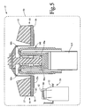
- FIG. 5 another embodiment of the present invention is shown wherein the cathode assembly 55 is located on an opposite side of the x-ray tube 12.
- the back plate 57 of the anode assembly 55 is moved to an opposite side of the front plate 56.
- This in turn also defines the anode surface 55a to be on the opposite side of the front plate 56 as shown.
- the straddle bearing assembly 140 of the present embodiment supports the newly configured anode assembly 55 is substantially the same manner as the bearing assembly 68 shown above in Figs. 2 to 4 except that the positioning of the bearings 90a, 90b in the bearing assembly 140 takes into account the new location of the centre of mass of the rotating assembly 79.
- each bearing is capable of substantially supporting an equal amount of load of the rotating assembly without requiring a large wheelbase between the bearings thereby reducing the amount of thermal compensation needed for the bearing assembly.
- the anode assembly does not substantially move during thermal heating and cooling of components in the x-ray tube thereby maintaining a steady size and location of the focal spot on the anode assembly.
- the bearing closer by way of a thermally conductive path to the anode assembly may be situated to support less load of the rotating assembly than the bearing situated further away from the anode assembly in a straddle bearing assembly.
- the design of the bearing assembly defines a cooling duct whereby oil or other coolant may flow to absorb heat thermally radiated from the anode assembly and cool the outer bearing races.
- the motor 80 is shown to reside on a side of the x-ray tube in which the cathode assembly 59 resides, it is possible to move the motor 80 to the opposite side of the x-ray tube.
- the x-ray tube of the present invention is described to be bipolar, the x-ray tube could optionally be configured with uni-polar characteristics where the cathode is at a -150,000 volt electrical potential and the anode is at ground potential. It is intended that the invention be construed as including all such modifications and alterations insofar as they come within the scope of the appended claims.
Description
- The present invention relates to straddle bearing assemblies, especially in relation to x-ray tube bearing assemblies and will be described with particular reference thereto. It is to be appreciated, however, that the invention may also find application in conjunction with bearing assemblies in other applications.
- Conventional diagnostic use of x-radiation includes the form of radiography, in which a still shadow image of the patient is produced on x-ray film, fluoroscopy, in which a visible real time shadow light image is produced by low intensity x-rays impinging on a fluorescent screen after passing through the patient, and computed tomography (CT) in which complete patient images are electrically reconstructed from x-rays produced by a high powered x-ray tube rotated about a patient's body.
- In a typical x-ray tube, electrons are generated from a filament coil heated to thermionic emission. The electrons are accelerated as a beam from a cathode through an evacuated chamber defined by a glass envelope, toward an anode. When the electrons strike the anode with large kinetic energies and experience a sudden deceleration, x-radiation is produced. An x-ray tube assembly is contained in a housing which includes a window transmissive to x-rays, such that radiation from the anode passes through the window toward a subject undergoing examination or treatment.
- Most x-ray tube designs employ filaments as a source of electrons. A filament is a coil of wire which is electrically energized so that electrons are thermionically emitted from the filament. The electrons are accelerated toward the anode due to a DC electrical potential difference between the cathode and the anode. Often this electrical potential difference is of the order of 150,000 volts, (±75,000 volts to ground) necessitating significant electrical insulation between the various tube components.
- In some low power x-ray tubes, electrons from a cathode filament are drawn at a high voltage to a stationary target anode. The impact of the electrons causes the generation of x-rays as well as significant thermal energy. In higher power x-ray tubes the thermal energy produced at the stationary target anode often becomes so large that the generated heat became a limiting factor in x-ray tube performance.
- In order to distribute the thermal loading and reduce anode temperature a rotating anode configuration has been adopted for many applications. In this configuration, an electron beam is focussed near a peripheral edge of the anode disk at a focal spot. As the anode rotates, a different portion of a circular path around the peripheral edge of the anode passes through the focal spot where x-rays are generated. Each portion along the circular path is heated to a very high temperature during the generation of x-rays and cooled as it is rotated before returning for the generation of x-rays. As higher power x-ray tubes are developed, the diameter and the mass of the rotating anode continues to grow. Further, when x-ray tubes are combined with conventional CT scanners, a gantry holding the x-ray tube is rotated around a patient's body in order to obtain complete images of the patient. Today, typical CT scanners revolve the x-ray tube around the patient's body at a rate of between 60-120 rotations-per-minute (RPM). In order for the x-ray tube to operate properly, the anode needs to be properly supported and stabilized from the effects of its own rotation and, in some instances, from centrifugal forces created by rotation of the x-ray tube about a patient's body.
- Typically, the anode is mounted on a stem and rotated by a motor. The anode, stem and other components rotated by the motor are part of a rotating assembly which is supported by a bearing assembly. The bearing assemblies found in most x-ray tubes today utilize either a cantilevered bearing arrangement or a straddle bearing arrangement. In a cantilevered bearing arrangement, all bearings are located on the same side of the rotating assembly's centre of mass. In a straddle bearing arrangement, bearings are located on both sides of the rotating assembly's centre of mass.
- One drawback to using the cantilevered bearing arrangement is that a bearing closest to the anode experiences a much greater load than the bearing(s) further from the anode. The bearing closest to the anode therefore has greater contact stresses which deleteriously effects the life of the entire bearing assembly and thus the x-ray tube life. If the size of the bearings closest to the anode were increased to distribute the contact stresses, the internal surface speeds of this bearing would increase and the bearing life would decrease due to a faster wear rate. Thus, the bearing closest to the anode would still typically fail first.
- In an effort to more equally distribute the load of the rotating assembly among the bearings, the straddle bearing arrangement was developed. Typical straddle bearing arrangements employ a large bearing-to-bearing distance. The bearing-to-bearing distance is sometimes referred to as a straddle or wheelbase. The large wheelbase is required to thermally insulate the bearings from the anode which is typically very hot. The anode is often in the range of 1200 degrees C. Heat from the anode is thermally conducted to the bearings through the predominantly metal bearing assembly.
- In conventional straddle bearing designs, heat transferred from the anode substantially equally effects each bearing on either side of the anode. This is the case since the bearings are typically symmetrically spaced an equidistance from the anode's centre of mass in order to share the load equally, and since the thermally conductive path between the anode and each bearing is the same length. Because each bearing on either side of the anode must be moved out an equal distance from the anode's centre of mass for thermal insulation purposes, the wheelbase of a conventional straddle bearing assembly is typically much larger than a wheelbase found in a cantilevered bearing arrangement. As discussed above, bearings in a cantilevered bearing arrangement are all on the same side of the anode. Thus, in a cantilevered bearing arrangement, once the bearing closest to the anode is thermally insulated the other bearing(s) can be placed at an appropriate distance further away from the bearing closest to the anode. This is possible since the thermally conductive path to the other bearings is always further than the thermally conductive path to the bearing closest to the anode. Therefore, thermal insulation does not require the large wheelbase in a cantilevered bearing arrangement that it does in a conventional straddle bearing arrangement.
- An unfortunate drawback to having a large wheelbase is that thermal compensation becomes much more difficult. Thermal compensation relates to the accommodations made in the bearing assembly in both the radial and axial directions to account for changes in bearing tolerances caused by temperature variances. The larger the wheelbase, the more thermal growth and shrinkage the bearing assembly design must be able to withstand. Thus, designing for thermal compensation in a straddle bearing assembly is extremely difficult given the large wheelbases dictated by the need to thermally insulate the bearings.
- One common technique used in both cantilevered and straddle bearing arrangements to ensure predictability in the effect temperature swings have on the bearing assembly is to only allow thermal movement in the bearing assembly to occur in one direction as opposed to compensating for thermal movement symmetrically about the bearing. This is typically done by securing in place at least one end of each component of the bearing assembly such that thermal shrinkage and growth occurs in a known direction at the opposite end. As a consequence, as components coupled to the bearing assembly expand and contract due to temperature variances, the anode also moves thereby creating changes to the focal spot. More specifically, as most conventional bearing assemblies restrict thermal expansion and contraction to occur in a direction substantially parallel with an axis of rotation of the anode, thermal movements typically cause the focal spot to change is size. Such change in size to the focal spot is undesirable as it causes blurring to images taken from the x-rays radiating from the anode. Further, such thermal expansion and contraction also causes undesired movement of the focal spot with respect to x-ray detectors outside of the x-ray tube which may additionally deleteriously effect the quality of the images taken.
- Typical implementations of straddle bearing designs also employ an outer bearing race rotation. Inner bearing race rotation is not available in straddle bearing designs as aligning bearings on opposite sides of the anode to handle such inner bearing race rotation has not been achievable. Aligning the bearings is difficult primarily because outer races for each bearing must be independently positioned on opposite sides of the anode in conventional straddle bearing designs and slight deviations from perfectly symmetrically placement of the outer bearings causes the anode supported by the bearing assembly to wobble during operation. Unfortunately, outer bearing race rotation increases surface speeds in the bearing and therefore increases the wear on the bearings. Further, because bearings in a straddle bearing assembly are physically located on both sides of the anode, difficulties arise in electrically isolating the bearings from high voltages. Specifically, if an x-ray tube is configured in a bi-polar arrangement, the cathode would be at a -75,000 volt potential while the anode would be at a +75,000 volt potential. As the bearing assembly is coupled to the anode assembly, the bearings are at the anode voltage potential. However, in a conventional straddle bearing assembly, at least one of the bearings is in close proximity to the cathode and therefor needs to be electrically insulated from the cathode voltage potentials in order to avoid undesirous arcing from occurring. As insulating the bearing from the cathode voltage potential is normally too difficult to accomplish, x-ray tube having a straddle bearing assembly typically implement a single ended configuration where the anode is at ground potential and the cathode is at -150,000 volts. Unfortunately this makes it difficult for such x-ray tubes to be used in a retrofit manner since most x-ray tube generators are configured to handle only a bi-polar topology.
-
JP-A-03/074033 US 3,758,801 describes a rotating anode X-ray tube wherein a cylindrical anode is mounted on a shaft, which shaft is supported by two space bearings.JP-A-62/200642 -
US 5,303,280 describes a large diameter anode X-ray tube with reinforced support. An anode disc is mounted on a rotating shaft held in the manner of cantilever bearing arrangement.US 3,790,836 also describes a rotating anode disc of the cantilever bearing arrangement type. - In order to solve the aforementioned problems, the present invention provides a straddle bearing assembly for an X-ray tube and a method of assembling an X-ray tube as defined in the appended claims.
- Ways of carrying out the invention will now be described in detail, by way of example, with reference to the accompanying drawings, in which:
-
Figure 1 is a diagrammatic illustration of a CT scanner in accordance with the present invention; -
Figure 2 is a top cross sectional view of an x-ray tube in accordance with the present invention; -
Figure 3 is a three-quarters isometric view of a straddle bearing assembly of the x-ray tube shown inFig. 2 ; -
Figure 4 is a top cross sectional view of the straddle bearing assembly ofFig. 3 ; and -
Figure 5 is an x-ray tube in accordance with an alternative embodiment of the present invention. - The present invention will now be described with reference to the drawings in which like reference numerals are used to refer to like elements throughout.
- Referring now to
Fig. 1 , aCT scanner 10 includes aradiation source 12, such as an x-ray tube, for projecting a fan beam of radiation through an examination region or scancircle 14. Thex-ray tube 12 is mounted on arotatable gantry 16 to rotate the fan beam of radiation around theexamination region 14. A collimator and shutterassembly 18 collimates the radiation to one or more planer beams and selectively gates the beams on and off.Radiation detectors 20 are mounted peripherally around theexamination region 14 and detect the radiation for processing. Amotor 24 provides motive power for rotating thegantry 16 continuously around theexamination region 14. - A
patient support 30 supports a patient subject in a reclined position. Thepatient support 30 is advanced through theexamination region 14, preferably at a constant velocity. As thepatient support 30 moves through theexamination region 14, thex-ray tube 12 is rotated about thepatient support 30 to ensure a complete set of information is available for reconstruction. - The
detectors 20 are coupled to viewreconstruction circuitry 30. Theview reconstruction circuitry 30 stores and processes data received from thedetectors 20 and maintains selected slice and volumetric images of the patient. Avideo processor 35 retrieves image information from theview reconstruction circuitry 30 and formats the image data into appropriate formats for display onvideo monitor 40 or the like. - Referring to
Fig. 2 , thex-ray tube 12 of the present invention is shown in more detail. Thex-ray tube 12 includes ahousing 50 filled with a heat transfer and electrically insulating fluid such as oil. Supported within thehousing 50 is anenvelope 52, typically comprised of glass or metal, within which an evacuated chamber or vacuum is defined. Disposed within theenvelope 52 is ananode assembly 55 and acathode assembly 59. Theanode assembly 55 shown is comprised of a molybdenumalloy front plate 56 and a graphite backplate 57. Thefront plate 56 of the anode assembly includes ananode surface 55a facing acathode focussing cup 60 of thecathode assembly 55. A portion of theanode surface 55a closest afocal spot 63 is made of a tungsten and rhenium composite in order to aid in the production of x-rays. Further, thefront plate 56 of theanode assembly 55 includes anelongated neck portion 58 as discussed in more detail below. It will be appreciated, however, that other single or multiple piece anode configurations made of any suitable substances could alternatively be used. - As is well known in the art, a
cathode filament 62 mounted to thecathode focussing cup 60 is energized to emit electrons which are accelerated to theanode assembly 55 to produce x-radiation for diagnostic imaging, therapy treatment and the like. Thecathode focussing cup 60 serves to focus electrons emitted from thecathode filament 62 to thefocal spot 63 on theanode surface 55a. The electrons are emitted from thecathode filament 62 and accelerated toward theanode assembly 55 due to a very large DC electrical potential difference between thecathode focussing cup 60 and theanode assembly 55. In the present embodiment, thecathode focussing cup 60 is at an electrical potential of -75,000 volts with respect to ground, and theanode assembly 55 is at an electrical potential of +75,000 volts with respect to ground thereby providing a bipolar configuration having a total electrical potential difference of 150,000 volts. Impact of the electrons from thecathode filament 62 onto theanode surface 55a typically causes theanode assembly 55 to be heated to a range of between 1100°-1400° C. - Referring now to
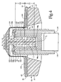
Figs. 2 and3 , the x-raytube anode assembly 55 is mounted for rotation about anaxis 65 via a straddle bearing assembly shown generally at 68. More specifically, thefront plate 56 of theanode assembly 55 is rigidly coupled toshaft 70 androtor 75. Therotor 75 includes arotor body 77 which is coupled toinduction motor 80 for rotating theshaft 70 andanode assembly 55 about theaxis 65. All of the components rotated by themotor 80, including therotor 75,rotor body 77,shaft 70 andanode assembly 55 are hereinafter referred to as rotatingassembly 79. Thestraddle bearing assembly 68 supports the load of the rotatingassembly 79 during rotation. The load of the rotatingassembly 79 includes the weight of all of the components of the rotatingassembly 79 including the weight of theanode assembly 55. - As shown in
Fig. 3 , theshaft 70 defines a pair ofinner races other bearing members 90a are received between theinner bearing race 82a and anouter bearing race 92a defined by anouter bearing member 94a. Similarly, a plurality of ball or other bearingmembers 90b are received between theinner bearing race 82b and anouter bearing race 92b defined by anouter bearing member 94b. Thebearings anode assembly 55 about theaxis 65. Eachbearing assembly 79 along theaxis 65. The centre of mass of the rotatingassembly 79 is shown along dashed line C (Fig. 2 ). - A bearing
housing 100 includes a firstelongated portion 101, a secondelongated portion 102, abase portion 103, and U shapedbend 104. Both the firstelongated portion 101 and the secondelongated portion 102 are substantially parallel to theaxis 65 and pass through the centre of mass C of the rotatingassembly 79. The firstelongated portion 101 and secondelongated portion 102 of the bearinghousing 100 which are coupled together at the U shapedbend 104 define a coolingduct 119. The bearinghousing 100 of the present embodiment is made of copper, however, it will be appreciated that other suitable materials could alternatively be used. - Each
outer bearing member spacer 106. Theouter bearing members spacer 106 are positioned within acavity 107 defined by theelongated portion 102 andbase portion 103 of the bearinghousing 100. A retainingspring 108 is positioned within thecavity 107 adjacent thebase portion 103 of the bearinghousing 100 and asnap ring 105 is rigidly secured to theelongated portion 102 of the bearinghousing 100 at an opposite end of thecavity 107. The retainingspring 108 and thesnap ring 105 serve to frictionally sandwich and secure theouter bearing members spacer 106 within thecavity 107. Similar to the bearinghousing 100, theouter bearing members spacer 106 are made of copper although other suitable materials could alternatively be used. - As best seen in
Fig. 2 , thex-ray tube 12 further includes anoil nozzle 115. Thenozzle 115 serves to pump oil in a direction indicated by arrows A1 through the coolingduct 119. The oil pumped by thenozzle 115 is obtained from a region R1 between theenvelope 52 andx-ray tube housing 50. As the oil travels through the coolingduct 119 along a path adjacent theelongated portion 102 of the bearinghousing 100, the oil serves to remove heat from theouter bearing members bearings duct 119 and passes along a path adjacent theelongated portion 101 of the bearinghousing 100, the oil serves to absorb heat radiated from thefront plate 56 and backplate 57 of theanode assembly 55. The oil flowing thorough the coolingduct 119 is typically flowing at a rate of approximately three gallons per minute although this rate may optionally be varied to obtain desired cooling effects. Further, although the present embodiment describes thenozzle 115 directing the flow of oil in the direction of arrows A1, it will be appreciated that thenozzle 115 may optionally reverse the flow of oil through the coolingduct 119. - As shown in
Fig. 4 , heat from theanode assembly 55 is primarily passed to thebearings paths path 120 begins at a peripheral edge of theanode assembly 55 which comes in contact with the electrons dissipated from thecathode filament 62 and travels along theelongated neck portion 58 of theanode assembly 55 to theshaft 70.Arrowed path 125 runs substantially parallel with theaxis 65 of rotation of theshaft 70 and has two end indicators. The first end indicator is shown at I1 and indicates an end of a full thermally conductive path to thebearing 90b from the peripheral edge of theanode assembly 55. The second end indicator is shown at I2 and indicates an end of a full thermally conductive path to thebearing 90a from the peripheral edge of theanode assembly 55. For purposes of this invention, the term "thermally conductive path" and derivations thereof includes a path by way of which heat is transferred between two points other than a path through a vacuum, air, or gas. - It will be appreciated that in the
straddle bearing assembly 68 of the present invention, the full thermally conductive path to thebearing 90a includes the full thermally conductive path to thebearing 90b. As the thermally conductive path to thebearing 90a is longer then the thermally conductive path to thebearing 90b, thebearing 90a will be at a cooler temperature then thebearing 90b. Therefore, once the bearing 90b is placed a sufficient distance along the thermally conductive path from the peripheral edge of theanode assembly 55 such that the heat dissipated to thebearing 90b in the region around I1 does not place undue temperature stress on thebearing 90b, bearing 90a is likewise protected. Further, because theanode assembly 55 includes theelongated neck portion 58, the thermally conductive path to thebearing 90b includes more area for heat from theanode assembly 55 to be dissipated via oil flowing through the coolingduct 119 thereby reducing thermal stresses placed on thebearings anode assembly 55 travels along theelongated neck portion 58, heat radiated from theelongated neck portion 58 may be absorbed through theelongated portion 101 of the bearinghousing 100 into the oil flowing through the coolingduct 119. Thus, by providing more area between the peripheral edge of theanode assembly 55 and thebearings bearings x-ray tube 12. - The wheelbase of the
straddle bearing assembly 68 of the present invention is shown to be a distance ofD 1 + D2 where D1 represents the distance between thebearing 90a and the centre of mass C of the rotatingassembly 79 and where D2 represents the distance between the bearing 90b and the centre of mass C of the rotatingassembly 79. In the present embodiment the distance D1 and D2 are substantially equal thereby providing that thebearing 90a and the bearing 90b each support a substantially equal load of the rotatingassembly 79. Further, because the full thermally conductive path to thebearing 90a includes the full thermally conductive path to thebearing 90b, the wheelbase D1+D2 for bearings of a desired size, temperature and wear rate is significantly less than a wheelbase needed in a conventional straddle bearing assembly having bearings of similar characteristics. As discussed above, the wheelbase of conventional straddle bearing assemblies were often very large since thermal insulation from the anode assembly required the bearings to be placed along thermally conductive paths from the anode assembly that were opposite in direction from one another. Since the thermally conductive path forbearings assembly 68. As discussed above in the background section, large wheelbases are undesirable since compensating the bearing assembly for thermal expansion and contraction is difficult with larger wheelbases. As the present invention does not require such a large wheel base to obtain similar wear rates on bearings of comparable size and temperature, design difficulties associated with needing to thermally compensate for large temperature variances is avoided. - It will be appreciated, that although the present embodiment shows the distance D1 and D2 between each bearing 90a, 90b, respectively, to be substantially equal in length, the present invention allows for the distances D1 and D2 to be independently varied to desired lengths. For instance, in order to account for the fact that the
bearing 90b is located along a shorter thermally conductive path to the peripheral edge of theanode assembly 55 than thebearing 90a and therefore is subjected to higher thermal stress, thebearing 90a may be moved into a position closer to the centre of mass C of the rotatingassembly 79 than the bearing 90b. In other words distance D1 is shorter than distance D2. Since the distance D1 is shorter than the distance D2, thebearing 90a supports a larger load of the rotatingassembly 79 than the bearing 90b. This in turn offsets some or all of the effects the higher temperature stress has on thebearing 90b thereby providing a bearingassembly 68 in which bothbearings assembly 68 is maximized. - Even though the
bearings assembly 79, thebearings anode assembly 55 relative thefront plate 56. More specifically, as shown inFig. 2 thefront plate 56 of theanode assembly 55 follows along theelongated neck portion 58 and through a junction between theanode assembly 55 and therotor 75. Thus, thebearings front plate 56 of theanode assembly 55 opposite the side facing thecathode cup 60. As such, thex-ray tube 12 may be configured with a bipolar arrangement since neither of thebearings straddle bearing assembly 68 are directly exposed to the electric field of thecathode assembly 55 and therefore additional electrical insulation with respect to thecathode assembly 55 is not necessary. - In operation, the motor 80 (
Fig. 2 ) rotates therotor 75 which is rigidly attached to theanode assembly 55 . Theanode assembly 55 is in turn rigidly attached to theshaft 70. - As such, the
anode assembly 55 andshaft 70 are both rotated about theaxis 65 while supported by thestraddle bearing assembly 68. Thebearings shaft 70. Inner bearing race rotation involves rotating theinner races Fig. 3 ) of the bearingassembly 68 while maintaining theouter races inner races shaft 70, inner bearing race rotation is achieved in the present embodiment by rotating theshaft 70. Inner bearing race rotation minimizes surface speeds leading to wear on thebearings anode assembly 55 causes less movement with respect to thebearings anode assembly 55 only causes rotation of thebearings inner races shaft 70. With outer bearing race rotation, a single rotation of theanode assembly 55 causes rotation of thebearings outer races outer bearing members outer bearing members shaft 70, a single rotation of theanode assembly 55 by way of the inner races provides less rotational movement of thebearings bearings x-ray tube 12. - Inner bearing race rotation is available in the present invention given the relationship between the
straddle bearing assembly 68 and theanode assembly 55. More specifically, thestraddle bearing assembly 68 provides bothbearings anode assembly 55. As such, symmetrically aligning theouter races outer bearing members cavity 107 predefined by the bearinghousing 100. By comparison, in a conventional straddle bearing assembly each bearing is placed on an opposite side of the anode assembly. Therefore, if inner bearing race rotation were attempted, the outer bearing races for each bearing would have to be independently aligned since a one piece bearing housing could not extend to both sides of the anode assembly. As discussed in the background section, such independent alignment of the outer bearing races in a straddle bearing design has not been achievable. - As the
anode assembly 55 heats during operation of thex-ray tube 12, theshaft 70 thermally expands in a direction indicated by arrow A2 (Fig. 2 ). Thermal expansion of theshaft 70 in an opposite direction of arrow A2 is not possible given that an opposite end of theshaft 70 closest to thebearing 90a is situated against thebase portion 103 of the bearinghousing 100 which is fixed in place. As theanode assembly 55 is rigidly coupled to theshaft 70, thermal expansion of theshaft 70 also causes thefront plate 56 of theanode assembly 55 to move in the direction of arrow A2. However, the present invention provides a counterbalance for the thermal expansion in theshaft 70. More specifically, as theelongated neck portion 58 of theanode assembly 55 thermally expands, thefront plate 56 of theanode assembly 55 is caused to move in a direction opposite the direction of arrow A2. Thermal expansion of theelongated neck portion 58 causes expansion in the direction opposite the arrow A2 since thefront plate 56 and backplate 57 of theanode assembly 55 are not fixed or restrained from movement by any component of thex-ray tube 12 in this direction. Thus, the positioning of thefront plate 56 of theanode assembly 55 remains substantially stationary during temperature changes in the x-ray tube. As such, thefocal spot 63 on theanode surface 55a also remains a substantially constant size regardless of the heating and cooling effects of theanode assembly 55 and bearingassembly 68. Further, thefocal spot 63 does not substantially move with respect to x-ray detectors (not shown) outside of thex-ray tube 12. - In an alternative embodiment of the present invention, the bearing
housing 100 of thex-ray tube 12 is made of sections which are glass and sections which are copper to help aid in cooling theanode assembly 55. More specifically, as shown infigure 4 , theelongated portion 101 is made of glass and theelongated portion 102 andbase portion 103 are made of copper. Theelongated portion 101 and theelongated portion 102 are joined together using known techniques such as brazing or welding at ajunction 130 along the U shapedbend 104 of the bearinghousing 100. It will be appreciated, however, that the junction between glass and copper could be made at any desirable location along the elongated stems 101 and 102. By providing the bearinghousing 100 with a glass portion along theelongated portion 101, heat thermally radiated from thefront plate 56 and backplate 57 of theanode assembly 55 is more readily absorbed by the oil flowing through the coolingduct 119. Thus, theanode assembly 55 is better able to be cooled and less heat is thermally conducted and radiated to thebearings - Referring now to
Fig. 5 , another embodiment of the present invention is shown wherein thecathode assembly 55 is located on an opposite side of thex-ray tube 12. To accommodate the new positioning of thecathode assembly 55, theback plate 57 of theanode assembly 55 is moved to an opposite side of thefront plate 56. This in turn also defines theanode surface 55a to be on the opposite side of thefront plate 56 as shown. Thestraddle bearing assembly 140 of the present embodiment supports the newly configuredanode assembly 55 is substantially the same manner as the bearingassembly 68 shown above inFigs. 2 to 4 except that the positioning of thebearings assembly 140 takes into account the new location of the centre of mass of the rotatingassembly 79. - One advantage of the above-described embodiments is that they provide for a straddle bearing design which allows inner bearing race rotation thereby minimizing wear on the bearings. Another advantage is that each bearing is capable of substantially supporting an equal amount of load of the rotating assembly without requiring a large wheelbase between the bearings thereby reducing the amount of thermal compensation needed for the bearing assembly. Still a further advantage is that the anode assembly does not substantially move during thermal heating and cooling of components in the x-ray tube thereby maintaining a steady size and location of the focal spot on the anode assembly. Yet another advantage is that the bearing closer by way of a thermally conductive path to the anode assembly may be situated to support less load of the rotating assembly than the bearing situated further away from the anode assembly in a straddle bearing assembly. Still another advantage is that the design of the bearing assembly defines a cooling duct whereby oil or other coolant may flow to absorb heat thermally radiated from the anode assembly and cool the outer bearing races.
- The invention has been described with reference to the preferred embodiments. Obviously, modifications and alterations will occur to others upon reading and understanding the preceding detailed description. For instance, referring to
Fig. 2 , although themotor 80 is shown to reside on a side of the x-ray tube in which thecathode assembly 59 resides, it is possible to move themotor 80 to the opposite side of the x-ray tube. Further, although the x-ray tube of the present invention is described to be bipolar, the x-ray tube could optionally be configured with uni-polar characteristics where the cathode is at a -150,000 volt electrical potential and the anode is at ground potential. It is intended that the invention be construed as including all such modifications and alterations insofar as they come within the scope of the appended claims.
Claims (10)
- A straddle bearing assembly for an x-ray tube, comprising: a first bearing (90a) and a second bearing (90b) disposed in a bearing housing (100) on opposite sides of a centre of mass (C) of a rotating assembly (79), said rotating assembly including a target (55), wherein the target (55) is a disc type anode assembly; and wherein a first thermally conductive path (I2, 125, 120) between the first bearing (90a) and the target (55) includes a second thermally conductive path (I1, 125, 120) between the second bearing (90b) and the target (55); and wherein the rotating assembly (79) further includes a shaft (70) coupled to the target (55) and the shaft is rotatably supported by the first bearing (90a) and by the second bearing (90b); wherein the bearing housing (100) includes a first elongated portion (101), a second elongated portion (102) coupled to the first elongated portion and a base portion (103) coupled to the second elongated portion; wherein a cooling duct (119) is defined by the first elongated portion (101) and the second elongated portion (102); and wherein the target includes an elongated portion (58) that thermally expands in a direction substantially opposite to a direction of thermal growth of the shaft;
characterized in that the first and the second elongated portions pass through the centre of mass (C) of the rotating assembly. - A straddle bearing assembly as claimed in claim 1, wherein a portion of the bearing housing is made of glass and a portion of the bearing housing is made of metal.
- A straddle bearing assembly as claimed in any one of claims 1 to 2, wherein one of the bearings supports more of the load of the rotating assembly than the other.
- A straddle bearing assembly as claimed in any one of claims 1 to 3, wherein the first bearing (90a) and the second bearing (90b) are positioned on the same side of the anode assembly (55).
- A straddle bearing assembly as claimed in any one of claims 1 to 4, wherein the first elongated portion (101) and the second elongated portion (102) pass through the centre of mass (C) of the rotating assembly (79).
- A straddle bearing assembly as claimed in claim 1, wherein cooling fluid flowing through the cooling duct cools the first bearing and the second bearing.
- A straddle bearing assembly as claimed in claim 6, wherein the cooling fluid is oil.
- A straddle bearing assembly as claimed in claim 1, wherein the shaft (70) defines a first inner race (82a) for receiving the first bearing (90a) and a second inner race (82b) for receiving the second bearing (90b).
- A straddle bearing assembly as claimed in claim 8, wherein the bearing assembly is adapted for providing an inner bearing race rotation.
- A method of assembling an x-ray tube, comprising the steps of: positioning a first bearing (90a) of a bearing assembly on a first side of a centre of mass (C) of a rotating assembly (79), the rotating assembly including a target, wherein the target is a disc type anode assembly (55); and positioning a second bearing (90b) of the bearing assembly on an opposite side of the centre of mass of the rotating assembly such that independent of an amount of load of the rotating assembly supported by the second bearing, the first bearing is in a closer thermal conductive path to the anode assembly than the second bearing;
wherein the rotating assembly (79) further includes a shaft (70) coupled to the target (55) and the shaft is rotatably supported by the first bearing (90a) and by the second bearing (90b);
wherein the bearing housing (100) includes a first elongated portion (101), a second elongated portion (102) coupled to the first elongated portion and a base portion (103) coupled to the second elongated portion; wherein a cooling duct (119) is defined by the first elongated portion (101) and the second elongated portion (102); and
wherein the target includes an elongated portion (58) that thermally expands in a direction substantially opposite to a direction of thermal growth of the shaft; and wherein the first and the second elongated portions pass through the centre of mass (C) of the rotating assembly.
Applications Claiming Priority (2)
| Application Number | Priority Date | Filing Date | Title |
|---|---|---|---|
| US08/967,475 US5978447A (en) | 1997-11-11 | 1997-11-11 | X-ray tube straddle bearing assembly |
| US967475 | 1997-11-11 |
Publications (3)
| Publication Number | Publication Date |
|---|---|
| EP0917176A2 EP0917176A2 (en) | 1999-05-19 |
| EP0917176A3 EP0917176A3 (en) | 2000-01-05 |
| EP0917176B1 true EP0917176B1 (en) | 2010-12-22 |
Family
ID=25512859
Family Applications (1)
| Application Number | Title | Priority Date | Filing Date |
|---|---|---|---|
| EP98307607A Expired - Lifetime EP0917176B1 (en) | 1997-11-11 | 1998-09-18 | Straddle bearing assembly for a rotating anode X-ray tube |
Country Status (4)
| Country | Link |
|---|---|
| US (1) | US5978447A (en) |
| EP (1) | EP0917176B1 (en) |
| JP (1) | JP4298826B2 (en) |
| DE (1) | DE69842062D1 (en) |
Families Citing this family (22)
| Publication number | Priority date | Publication date | Assignee | Title |
|---|---|---|---|---|
| US6335512B1 (en) * | 1999-07-13 | 2002-01-01 | General Electric Company | X-ray device comprising a crack resistant weld |
| JP3663111B2 (en) * | 1999-10-18 | 2005-06-22 | 株式会社東芝 | Rotating anode X-ray tube |
| DE10048488A1 (en) * | 2000-09-29 | 2002-04-25 | Siemens Ag | Setting up the cooling of a surface that rotates about an axis of rotation and faces the axis of rotation |
| JP2002198004A (en) * | 2000-12-26 | 2002-07-12 | Toshiba Corp | Rotary anode x-ray tube, and rotary anode x-ray tube device using the same |
| US6603834B1 (en) | 2001-09-18 | 2003-08-05 | Koninklijke Philips Electronics, N.V. | X-ray tube anode cold plate |
| US6707882B2 (en) * | 2001-11-14 | 2004-03-16 | Koninklijke Philips Electronics, N.V. | X-ray tube heat barrier |
| DE10241178B4 (en) * | 2002-09-05 | 2007-03-29 | Mt Aerospace Ag | Isokinetic gantry arrangement for the isocentric guidance of a particle beam and method for its design |
| US20050226385A1 (en) * | 2004-03-30 | 2005-10-13 | Simpson James E | X-ray tube for a computed tomography system and method |
| US7197115B2 (en) * | 2004-08-10 | 2007-03-27 | General Electric Company | Cantilever and straddle x-ray tube configurations for a rotating anode with vacuum transition chambers |
| JP4846214B2 (en) * | 2004-08-27 | 2011-12-28 | 株式会社東芝 | Rotating anode X-ray tube |
| US20080037703A1 (en) * | 2006-08-09 | 2008-02-14 | Digimd Corporation | Three dimensional breast imaging |
| US7505564B2 (en) * | 2006-10-23 | 2009-03-17 | General Electric Company | Composite coating for improved wear resistance for x-ray tube bearings |
| US7492869B1 (en) * | 2006-10-23 | 2009-02-17 | General Electric Company | Titanium carbide plus silver coated balls for x-ray tube bearings |
| US7397897B2 (en) * | 2006-10-23 | 2008-07-08 | General Electric Company | Composite coating for improved wear resistance for x-ray tube bearings |
| JP2008243694A (en) * | 2007-03-28 | 2008-10-09 | Jtekt Corp | Rolling bearing for x-ray tube and x-ray tube apparatus |
| US7949099B2 (en) | 2007-07-05 | 2011-05-24 | Newton Scientific Inc. | Compact high voltage X-ray source system and method for X-ray inspection applications |
| US8284899B2 (en) * | 2007-11-21 | 2012-10-09 | Varian Medical Systems, Inc. | X-ray tube having a focal spot proximate the tube end |
| US9271689B2 (en) * | 2010-01-20 | 2016-03-01 | General Electric Company | Apparatus for wide coverage computed tomography and method of constructing same |
| WO2012026381A1 (en) * | 2010-08-24 | 2012-03-01 | 株式会社 日立メディコ | X-ray tube device and x-ray ct device |
| JP5942247B2 (en) * | 2011-12-27 | 2016-06-29 | 株式会社日立製作所 | Rotating anode X-ray tube device |
| US9305739B2 (en) * | 2012-10-16 | 2016-04-05 | General Electric Company | Apparatus for ultra high vacuum thermal expansion compensation and method of constructing same |
| DE102013215673B4 (en) * | 2013-08-08 | 2016-05-25 | Siemens Aktiengesellschaft | Single pole X-ray source |
Citations (1)
| Publication number | Priority date | Publication date | Assignee | Title |
|---|---|---|---|---|
| JPH0330247A (en) * | 1989-06-28 | 1991-02-08 | Hitachi Medical Corp | Rotating anode x-ray tube |
Family Cites Families (12)
| Publication number | Priority date | Publication date | Assignee | Title |
|---|---|---|---|---|
| US3758801A (en) * | 1972-05-22 | 1973-09-11 | Machlett Lab Inc | Cylindrical target x-ray tube |
| US3790836A (en) * | 1972-10-02 | 1974-02-05 | M Braun | Cooling means for electrodes |
| FR2235478B1 (en) * | 1973-06-29 | 1977-02-18 | Radiologie Cie Gle | |
| DE2610660C3 (en) * | 1976-03-13 | 1979-02-22 | Philips Patentverwaltung Gmbh, 2000 Hamburg | Rotating anode X-ray tube |
| JPS5578449A (en) * | 1978-12-08 | 1980-06-13 | Toshiba Corp | Rotary anode x-ray tube |
| DE3022618A1 (en) * | 1980-06-16 | 1982-01-21 | Siemens AG, 1000 Berlin und 8000 München | TURNING ANODE TUBE TUBES |
| US4545064A (en) * | 1983-10-28 | 1985-10-01 | Litton Systems, Inc. | X-ray tube rotor mounting |
| JPS62200642A (en) * | 1986-02-27 | 1987-09-04 | Shimadzu Corp | Rotary anode x-ray tube |
| JPH0374033A (en) * | 1989-08-16 | 1991-03-28 | Hitachi Medical Corp | Rotary anode x-ray tube |
| CN1024872C (en) * | 1991-01-31 | 1994-06-01 | 东芝株式会社 | Rotary anode type X-ray tube |
| JPH04370636A (en) * | 1991-06-19 | 1992-12-24 | Hitachi Medical Corp | Rotary anode x-ray tube |
| US5303280A (en) * | 1992-11-27 | 1994-04-12 | Picker International, Inc. | Large diameter anode X-ray tube with reinforced support |
-
1997
- 1997-11-11 US US08/967,475 patent/US5978447A/en not_active Expired - Lifetime
-
1998
- 1998-09-18 EP EP98307607A patent/EP0917176B1/en not_active Expired - Lifetime
- 1998-09-18 DE DE69842062T patent/DE69842062D1/en not_active Expired - Lifetime
- 1998-11-09 JP JP31768398A patent/JP4298826B2/en not_active Expired - Fee Related
Patent Citations (1)
| Publication number | Priority date | Publication date | Assignee | Title |
|---|---|---|---|---|
| JPH0330247A (en) * | 1989-06-28 | 1991-02-08 | Hitachi Medical Corp | Rotating anode x-ray tube |
Also Published As
| Publication number | Publication date |
|---|---|
| JPH11224627A (en) | 1999-08-17 |
| DE69842062D1 (en) | 2011-02-03 |
| EP0917176A2 (en) | 1999-05-19 |
| US5978447A (en) | 1999-11-02 |
| EP0917176A3 (en) | 2000-01-05 |
| JP4298826B2 (en) | 2009-07-22 |
Similar Documents
| Publication | Publication Date | Title |
|---|---|---|
| EP0917176B1 (en) | Straddle bearing assembly for a rotating anode X-ray tube | |
| EP1449232B1 (en) | Rotating anode x-ray tube heat barrier | |
| US6430260B1 (en) | X-ray tube anode cooling device and systems incorporating same | |
| US8520803B2 (en) | Multi-segment anode target for an X-ray tube of the rotary anode type with each anode disk segment having its own anode inclination angle with respect to a plane normal to the rotational axis of the rotary anode and X-ray tube comprising a rotary anode with such a multi-segment anode target | |
| JP5265906B2 (en) | Convection cooled X-ray tube target and manufacturing method thereof | |
| US6041100A (en) | Cooling device for x-ray tube bearing assembly | |
| US5493599A (en) | Off-focal radiation limiting precollimator and adjustable ring collimator for x-ray CT scanners | |
| CN101026077B (en) | Compact source of a high-brightness X-ray beam | |
| US6125169A (en) | Target integral heat shield for x-ray tubes | |
| EP0496945A1 (en) | Rotary-anode type x-ray tube | |
| US6594341B1 (en) | Liquid-free x-ray insert window | |
| EP0330336B1 (en) | High intensity X-ray source using bellows | |
| JP4309290B2 (en) | Liquid metal heat pipe structure for X-ray targets | |
| JP2001216928A (en) | X-ray tube | |
| US6603834B1 (en) | X-ray tube anode cold plate | |
| JP3030069B2 (en) | X-ray tube | |
| KR20230095763A (en) | X-ray tube including rotating anode | |
| JP2001276052A (en) | Cathode scanning type x-ray generator and x-ray ct scanner | |
| JP2001276041A (en) | Cathode scanning type x-ray generator and x-ray ct scanner | |
| JP2001276043A (en) | Cathode scanning type x-ray generator and x-ray ct scanner | |
| JP2001276045A (en) | Cathode scanning type x-ray generator and x-ray ct scanner | |
| JP2001276050A (en) | Cathode scanning type x-ray generator and x-ray ct scanner | |
| JPS6182642A (en) | Rotating anode type x-ray tube |
Legal Events
| Date | Code | Title | Description |
|---|---|---|---|
| PUAI | Public reference made under article 153(3) epc to a published international application that has entered the european phase |
Free format text: ORIGINAL CODE: 0009012 |
|
| AK | Designated contracting states |
Kind code of ref document: A2 Designated state(s): DE FR NL |
|
| AX | Request for extension of the european patent |
Free format text: AL;LT;LV;MK;RO;SI |
|
| PUAL | Search report despatched |
Free format text: ORIGINAL CODE: 0009013 |
|
| AK | Designated contracting states |
Kind code of ref document: A3 Designated state(s): AT BE CH CY DE DK ES FI FR GB GR IE IT LI LU MC NL PT SE |
|
| AX | Request for extension of the european patent |
Free format text: AL;LT;LV;MK;RO;SI |
|
| 17P | Request for examination filed |
Effective date: 20000629 |
|
| AKX | Designation fees paid |
Free format text: DE FR NL |
|
| RAP1 | Party data changed (applicant data changed or rights of an application transferred) |
Owner name: MARCONI MEDICAL SYSTEMS, INC. |
|
| 17Q | First examination report despatched |
Effective date: 20020118 |
|
| RAP1 | Party data changed (applicant data changed or rights of an application transferred) |
Owner name: PHILIPS MEDICAL SYSTEMS (CLEVELAND), INC. |
|
| RAP1 | Party data changed (applicant data changed or rights of an application transferred) |
Owner name: KONINKLIJKE PHILIPS ELECTRONICS N.V. |
|
| GRAP | Despatch of communication of intention to grant a patent |
Free format text: ORIGINAL CODE: EPIDOSNIGR1 |
|
| GRAS | Grant fee paid |
Free format text: ORIGINAL CODE: EPIDOSNIGR3 |
|
| GRAA | (expected) grant |
Free format text: ORIGINAL CODE: 0009210 |
|
| AK | Designated contracting states |
Kind code of ref document: B1 Designated state(s): DE FR NL |
|
| REF | Corresponds to: |
Ref document number: 69842062 Country of ref document: DE Date of ref document: 20110203 Kind code of ref document: P |
|
| REG | Reference to a national code |
Ref country code: DE Ref legal event code: R096 Ref document number: 69842062 Country of ref document: DE Effective date: 20110203 |
|
| REG | Reference to a national code |
Ref country code: NL Ref legal event code: VDEP Effective date: 20101222 |
|
| PG25 | Lapsed in a contracting state [announced via postgrant information from national office to epo] |
Ref country code: NL Free format text: LAPSE BECAUSE OF FAILURE TO SUBMIT A TRANSLATION OF THE DESCRIPTION OR TO PAY THE FEE WITHIN THE PRESCRIBED TIME-LIMIT Effective date: 20101222 |
|
| PLBE | No opposition filed within time limit |
Free format text: ORIGINAL CODE: 0009261 |
|
| STAA | Information on the status of an ep patent application or granted ep patent |
Free format text: STATUS: NO OPPOSITION FILED WITHIN TIME LIMIT |
|
| 26N | No opposition filed |
Effective date: 20110923 |
|
| REG | Reference to a national code |
Ref country code: DE Ref legal event code: R097 Ref document number: 69842062 Country of ref document: DE Effective date: 20110923 |
|
| REG | Reference to a national code |
Ref country code: DE Ref legal event code: R082 Ref document number: 69842062 Country of ref document: DE Representative=s name: VOLMER, GEORG, DIPL.-ING., DE |
|
| REG | Reference to a national code |
Ref country code: DE Ref legal event code: R082 Ref document number: 69842062 Country of ref document: DE Representative=s name: MEISSNER BOLTE PATENTANWAELTE RECHTSANWAELTE P, DE Effective date: 20140331 Ref country code: DE Ref legal event code: R082 Ref document number: 69842062 Country of ref document: DE Representative=s name: VOLMER, GEORG, DIPL.-ING., DE Effective date: 20140331 Ref country code: DE Ref legal event code: R081 Ref document number: 69842062 Country of ref document: DE Owner name: KONINKLIJKE PHILIPS N.V., NL Free format text: FORMER OWNER: KONINKLIJKE PHILIPS ELECTRONICS N.V., EINDHOVEN, NL Effective date: 20140331 |
|
| REG | Reference to a national code |
Ref country code: FR Ref legal event code: CD Owner name: KONINKLIJKE PHILIPS ELECTRONICS N.V., NL Effective date: 20141126 Ref country code: FR Ref legal event code: CA Effective date: 20141126 |
|
| REG | Reference to a national code |
Ref country code: FR Ref legal event code: PLFP Year of fee payment: 18 |
|
| REG | Reference to a national code |
Ref country code: FR Ref legal event code: PLFP Year of fee payment: 19 |
|
| PGFP | Annual fee paid to national office [announced via postgrant information from national office to epo] |
Ref country code: FR Payment date: 20160928 Year of fee payment: 19 |
|
| PGFP | Annual fee paid to national office [announced via postgrant information from national office to epo] |
Ref country code: DE Payment date: 20161130 Year of fee payment: 19 |
|
| REG | Reference to a national code |
Ref country code: DE Ref legal event code: R082 Ref document number: 69842062 Country of ref document: DE Representative=s name: MEISSNER BOLTE PATENTANWAELTE RECHTSANWAELTE P, DE |
|
| REG | Reference to a national code |
Ref country code: DE Ref legal event code: R119 Ref document number: 69842062 Country of ref document: DE |
|
| REG | Reference to a national code |
Ref country code: FR Ref legal event code: ST Effective date: 20180531 |
|
| PG25 | Lapsed in a contracting state [announced via postgrant information from national office to epo] |
Ref country code: DE Free format text: LAPSE BECAUSE OF NON-PAYMENT OF DUE FEES Effective date: 20180404 |
|
| PG25 | Lapsed in a contracting state [announced via postgrant information from national office to epo] |
Ref country code: FR Free format text: LAPSE BECAUSE OF NON-PAYMENT OF DUE FEES Effective date: 20171002 |