EP0916982A2 - Commutateur optique - Google Patents
Commutateur optique Download PDFInfo
- Publication number
- EP0916982A2 EP0916982A2 EP98121317A EP98121317A EP0916982A2 EP 0916982 A2 EP0916982 A2 EP 0916982A2 EP 98121317 A EP98121317 A EP 98121317A EP 98121317 A EP98121317 A EP 98121317A EP 0916982 A2 EP0916982 A2 EP 0916982A2
- Authority
- EP
- European Patent Office
- Prior art keywords
- light
- output
- optical
- deflector
- locations
- Prior art date
- Legal status (The legal status is an assumption and is not a legal conclusion. Google has not performed a legal analysis and makes no representation as to the accuracy of the status listed.)
- Withdrawn
Links
Images


Classifications
-
- G—PHYSICS
- G02—OPTICS
- G02B—OPTICAL ELEMENTS, SYSTEMS OR APPARATUS
- G02B26/00—Optical devices or arrangements for the control of light using movable or deformable optical elements
- G02B26/004—Optical devices or arrangements for the control of light using movable or deformable optical elements based on a displacement or a deformation of a fluid
-
- G—PHYSICS
- G02—OPTICS
- G02B—OPTICAL ELEMENTS, SYSTEMS OR APPARATUS
- G02B6/00—Light guides; Structural details of arrangements comprising light guides and other optical elements, e.g. couplings
- G02B6/24—Coupling light guides
- G02B6/26—Optical coupling means
- G02B6/35—Optical coupling means having switching means
- G02B6/3538—Optical coupling means having switching means based on displacement or deformation of a liquid
-
- G—PHYSICS
- G02—OPTICS
- G02B—OPTICAL ELEMENTS, SYSTEMS OR APPARATUS
- G02B6/00—Light guides; Structural details of arrangements comprising light guides and other optical elements, e.g. couplings
- G02B6/24—Coupling light guides
- G02B6/26—Optical coupling means
- G02B6/35—Optical coupling means having switching means
- G02B6/351—Optical coupling means having switching means involving stationary waveguides with moving interposed optical elements
- G02B6/3522—Optical coupling means having switching means involving stationary waveguides with moving interposed optical elements the optical element enabling or impairing total internal reflection
-
- G—PHYSICS
- G02—OPTICS
- G02B—OPTICAL ELEMENTS, SYSTEMS OR APPARATUS
- G02B6/00—Light guides; Structural details of arrangements comprising light guides and other optical elements, e.g. couplings
- G02B6/24—Coupling light guides
- G02B6/26—Optical coupling means
- G02B6/35—Optical coupling means having switching means
- G02B6/354—Switching arrangements, i.e. number of input/output ports and interconnection types
- G02B6/3554—3D constellations, i.e. with switching elements and switched beams located in a volume
- G02B6/3556—NxM switch, i.e. regular arrays of switches elements of matrix type constellation
Definitions
- the present invention relates to an nxm optical switch for use in an optical system such as a switching network, n being ⁇ 1, m>1.
- Optical matrix switches for example, nxm optical switches, are capable of connecting one or more input fibers to any one of a number of optical output fibers by reflecting a signal on a selected one of an array of reflective means.
- an array of parallel input optical fibers are arranged orthogonal to an array of parallel output optical fibers; however these switches are usually bi-directional such that all ports can function as input/output ports.
- Movable or state changing reflective means are arranged at each of the intersections between the optical paths launched from input and output fibers for selectively coupling a signal from an input fiber to a desired output fiber.
- Switches of this type are constructed using a wide variety of structures, including mechanical, opto-electronic and magnetic actuation.
- An nxn optical matrix switch of this type requires n 2 reflective means to allow n input ports to be connected to n output ports in a non-blocking fashion.
- the slots are filled with a liquid that matches the refractive index of the waveguides.
- Electrodes positioned adjacent to the slots form gas bubbles in a selected slot by electrolysis.
- One of the electrodes catalyses the reformation of the liquid from the bubble components when a voltage pulse is applied.
- Light in the input waveguides is transmitted through an intersection in the presence of liquid, but is reflected into an output waveguide in the presence of bubbles.
- nxm optical matrix switch is disclosed in United States patent No. 4,580,873 to Levinson.
- This mxn optical switch is formed on a semiconductor substrate. Grooves are etched at the edges of the substrate to accommodate input and output optical fibers so that the output fibers are placed orthogonal to the light paths of the input fibers.
- an electromechanically actuated mirror is provided which in one position permits passage of light from its associated input fiber to a subsequent mirror, and in another position deflects the light to its associated output fiber.
- the reflective means in this mxn optical switch matrix comprises an array of gratings formed in a semiconductor heterostructure.
- the gratings have two states. When a refractive index change is induced, the Bragg condition for the light received from an optical signal is met, and a portion of the light is diffracted from the row in which it is propagating into a column toward another optical fiber. In the off state, if the incident light does not satisfy the Bragg condition, the beam propagates unperturbed through the grating to be sampled by a subsequent switch.
- Switches vary in size from the minimum 1x2 to very large matrixes exceeding 100x100.
- a rotatable arm with a collimating lens is attached to the shaft for rotation along the pitch circle, with a small distance therebetween, so that the lens of the arm can be optically connected with the lenses on the faceplate when the rotatable arm is moved by means of the shaft of the stepping motor.
- An optical input fibre is connected to the collimating lens (hereafter called a lens-to-fibre unit) of the arm and a plurality of optical output fibres are attached to the respective collimating lenses on the faceplate for a switching operation when the rotatable arm moves from one position to another.
- optical switches be efficient, fast and compact.
- telecommunication networks have evolved over the years and have become more complex, a need has arisen for a matrix switching system capable of optically coupling any one of a large number of other fibers to another.
- the switching system it is desirable for the switching system to be "non-blocking", i.e. the switching of one input fiber to an output fiber should not interfere with the light transmission of any other input fiber to any other output fiber.
- This invention obviates many of the potential problems associated with Laughlin's disclosed invention.
- an optical switch comprising:
- an optical switch comprising:
- an optical deflection switch comprising: a first light transmissive prism, having a plurality of input ports and having a plurality of sequential deflection regions coupled thereto disposed to receive light launched into any of the plurality of input ports, each deflection region having at least two selectable deflective surfaces disposed, upon selection to reflect the light to a next sequential deflection region so that a beam launched in at least one of the input ports follows one of a plurality of selectable paths to one of a plurality of output locations;
- an optical deflection switch for selectably switching any of n input signals to at least m output locations, comprising: a first module including:
- an optical switch comprising: a prism having n input ports and having a first plurality light reflective regions and a second plurality of light reflective regions, each light reflective region in said first plurality being disposed to receive light from one of the n input ports and to reflect the light to one of the reflective regions in the second plurality of light reflective regions in a first mode of operation;
- an optical deflection switch comprising:
- an optical deflection switch comprising:
- an optical deflection switch comprising:
- a method is provided of switching an optical signal from an input port to one of a plurality of output ports, comprising the step of: launching a beam of light into the input port;
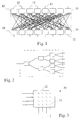
- a single stage switched distribution, switched recombination (SDSR) design is shown wherein each port 12 is connected to a 1xP rotary fibre switch, as is described by Duck et al. mentioned above, where P is the overall dimension of the matrix.
- optical fibres couple each switch on one side of the matrix to each switch on the other side of the matrix.
- each of the 1x8 switches can be formed of 7 1x2 optical switches configured as shown in Fig. 2.
- 2n(n-1) 112 1x2 optical switches would be required.
- FIG. 3 a 4x4 optical matrix switch 30 is shown having 16 movable reflective elements 32. It should be noted that an 8x8 optical switch of a similar architecture requires 64 reflective elements 32.
- a binary optical deflection switch is shown comprised of a trapezoidal shaped block 10 having an input port 6 and having output ports 7a to 7h, wherein ports 7a, 7g, and 7h are shown.
- the block 10 is made of light transmissive material such as glass.
- Light transmissive glass blocks 12, 14 and 16 having three different thicknesses t, 2t, and 4t and having the same refractive index as the trapezoidal shaped block 10 are shown to be adjacent the block 10, and spaced from the block 10 by a thin layer of silicone 15 having a refractive index that is substantially the same as the glass blocks or an equivalent resilient index matching buffer material.
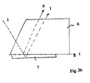
- FIG. 3b A more basic 1x2 optical switch is shown in Fig. 3b having a single input port and two output ports.
- An input beam is launched from the left of the figure into a block of glass 6.
- the glass block 7 (and its buffer material not shown) is optically contacting the block 6, light is routed to port 1.
- the glass block 7 is moved so that it does not contact the block 6, light is routed to port 0.
- the thickness t of the block 7 will determine the spacing between ports 0 and 1.
- the alternate optical paths to the ports 0 and 1 are parallel paths.
- the 8 output ports 0, ... 5, 7 shown in Fig. 3a are evenly spaced. This becomes even more important in the nxn optical switch described hereafter.
- the blocks 12, 14, and 16 are individually controllably movable such that they are in contact with the block 10 (via the elastomer index matching material) or such that they are lifted off of the block 10.
- the lines 18a, 18b, and 18c which lead to ports 0, 5, and 7 respectively.
- the blocks 12, 14, and 16 can be stationary and can be selectively filled with an index matching fluid or filled with air to allow transmission or reflection upon selection thereof.
- This switching actuation is described in greater detail in reference to Figs. 4 to 10.
- selectable optical paths from the block 12 to the block 14 are parallel and selectable optical paths from the block 14 to 16 are also parallel to one another.
- this parallelism ensures that the output beams will also be parallel to one another making the coupling of the output light considerably easier.
- this embodiment is believed to be an improvement over Laughlin's switch which relies on using a wedge
- one disadvantage of this embodiment that is obviated in the switch shown in Fig. 4 is that the blocks 12, 14, and 16 must increase in thickness for the receiving output ports to be evenly spaced. For a 1x64 switch this requires blocks of substantial thickness.
- the difficulty is obviated.
- a first diffractor 41a in the form of a light transmissive prism is optically coupled with a second diffractor 41b in the form of a second light transmissive prism disposed at right angles to the first diffractor 41a.
- the switch can be considerably small allowing an array of input beams to be switched in a first direction to a plurality of intermediate locations, and subsequently in an orthogonal direction to a plurality of output ports, thereby providing a 4x4 non-blocking switch.
- Four input ports 1a through 4a are disposed along an upper face of the prism 41a. However, it should be noted that if ports 2a through 4a were not provided as is shown in Fig. 9b, a 1x16 optical switch would result.
- these ports are formed by coupling four input optical fibres to four predetermined locations about the face of the prism 41a using standard optical fibre tube coupling technology.
- the output ports 1b through 4b are formed along a lower face of the second diffractor 41b.
- the presence of controllable two-state optical switching elements are generally shown as longitudinal rectangular regions at 10a, through 10d, 20a through 20d, 30a through 30d, and 40a through 40d and will be described with reference to Fig. 5 in greater detail with reference to switching elements 10a and 20a.
- the distance “d” is selected in dependence upon the required spacing between the ports on one side of the device.
- a similar arrangement is shown at the next switching element 20a and each of switching elements 20b to 20d (not shown) wherein a standard switching block is sandwiched between an outside face of the prism 41b and a glass block 54b having a thickness of "2d" units.
- the second prism 41b also has similar switching elements each having a standard switching block 52.
- the row of elements 30a to 30d each have a glass block of thickness "d" and the row of elements 40a to 40d each have a glass block of thickness "2d" adjacent a switching block 52, wherein in a linear switch that is not folded by a second prism being orthogonal to the first prism as is the case in this embodiment, the thickness of the glass blocks must increase at each subsequent element.
- blocks 54a, 54b, 54c, and 54d with different thicknesses a beam launched into the port 1a the beam can be switched to different positions A, B, C, or D as shown in Fig. 5 by controlling the two switches 10a and 20a.
- any of the input ports can be switched to any of the output ports of this bi-directional switch by switching blocks 52 to achieve this end.
- Each standard switching block 52 used for each of the 2nLog 2 n switches are made of a light transmissive material preferably having a same refractive index as the prism.
- Each block 52 has therewithin a cavity into which an refractive index matching liquid is pumped in a first transmissive switching mode. In the first switching mode light incident upon the block 52 is transmitted therethrough. Alternatively in a second deflecting switching mode at least some of the index matching fluid is expelled from the cavity so that air is within the cavity and light incident upon the block 52 from the prism is deflected to a next serial block 52.
- a light deflecting region includes a switching element in the form of a glass block 52a having a conduit or longitudinal bore along its length.
- Another glass block 52b of a first dimension "d" or 52bb of dimension substantially about “2d” is placed directly on top of the block 52a.
- Inlet and outlet conduits in the form of tubes 52aa are used to move index matching fluid and the air bubble shown through the longitudinal bore within 52a as is required.
- the beam In operation when a beam launched into the switch is incident upon the bubble, the beam is reflected as is shown in the switch block 52a on the right of the figure; alternatively, as is shown on the left, when the beam is incident on the index matching fluid, the beam is transmitted through the longitudinal bore.
- Fig. 5c illustrates the mechanism for moving the fluid contained within the tube 52aa.
- the exemplary embodiment depicts a solenoid, which can be actuated to move the fluid within the circuit shown, defined by the longitudinal bore and the tube 52aa.
- Fig. 5c The operation of the optical switch of Fig. 4 can more readily be understood while referring to Fig. 5c.
- Fig. 5c is shown to have 3 input/output ports and 4 output/input ports instead of the 4 inputs and 4 outputs shown in the 4x4 switch as shown in Fig. 4.
- the input port in/out 1 can provide its output signal to any one of 4 output locations shown in the row facing the port.
- each of the ports in/out2, and in/out3 can provide an output signal to one of 4 output locations depending upon the selection of the switches.
- the switch is folded to allow any of the beams in the direction from the port in/out1 destined for one of the 4 output ports in the row facing the port in/out1 to be routed orthogonally to one of the output ports.
- g. 6 shows in more detail the alternative paths an input beam may be routed along in switching from a first input port to one of four output locations at an upper face of the prism 41a.
- an input beam launched into the first port 1a can be reflected at location 60a or to the location 61a.
- one of the two beams reflecting from 60a or 61a can be reflected at locations 61b, 61bb, or 60bb or 60b, thereby providing 1 to 4 switching.
- 1 to 4 switching can independently occur for other light beams launched into ports 2a, 3a, and 4a.
- 4 input beams can be switched (in a semi-blocking manner) to 16 output locations 66 shown in dotted outline.
- the 4 input beams can be switched in a non-blocking manner to 4 output locations.
- the second prism 41b provides a means of directing light launched into all of the input ports to any of the 16 output locations 66 shown in Fig. 6 and to any of the output ports 1b, 2b, 3b, or 4b, in a non-blocking manner.
- the prisms 41a and 41b including switching elements are identical.
- the ports 1b to 4b must be accurately optically aligned with the input ports 1a to 4a
- any of the ports 1a through 4a can be switched to any of ports 1b through 4b by controlling appropriate switching elements 52.
- light launched into any of ports 1b through 4b can be switched to ports 1a through 4a through control of the switching elements 52, thereby providing an nxn non-blocking compact bi-directional optical switch having no movable switching elements. Switching is accomplished by the removal or insertion of a fluid into the cavity within a switching element 52.
- the switching elements can be formed within a prism 71 by boring channels 74 parallel to adjacent sides of the prism 71 that can be filled with a fluid or have fluid evacuated therefrom to switch between transmissive and deflective switching modes of operation.
- One of the switching elements 74 is shown to be closer to its adjacent side than the other element 74. This variation in distance allows a single input beam to be switched to any of four output positions A, B, C, and D.
- FIG. 8 depicts a blocking version of the 4x4 optical switch.
- switching elements 110, 120, 130, and 140 are required similar to, but wider than elements 10a, 20a, 30a and 40a shown in Fig. 5.
- Each of the elements 110 through 140 requires a switching block sandwiched between a face of the prism and a light transmissive block of a predetermined thickness.
- Fig. 9 shows yet an alternative embodiment of a 4x4 non-blocking optical switch.
- a deflector prism 90 angled such that light at the 16 output locations 66 are deflected to 16 output locations 96.
- Four additional switching elements 10e through 10h and 20e through 20h are required at two faces of the prism adjacent to the elements 10a through 10d and 20a through 20d to direct light from any of the output locations 96 to any of the output ports 90.
- any beam launched into any of ports 1a through 4a can be coupled to any of ports 1b through 4b.
- the prism 90 is shown to transpose beams at the output locations 91a adjacent the input./output waveguides by providing the beams at the adjacent array of locations 91b.
- Fig. 10 shows an embodiment similar to the one shown in Fig. 9, however an additional prism 100 is directly optically coupled with the larger prism 41a.
- Input/output ports 1a to 8a and output/input ports 1b to 8b are disposed at an end face of the prism 100.
- the diagram illustrates a path of a beam launched into port 1a as it propagates through prisms 100, 41a and 90 to reach output/input port 1b.
- the beam launched into port 1a is shown as a dotted line and entering the location 66a from the below to exit upward to the prism 90.
- the prism 90 reflects (and maps) the beam to a similar location 96a on the array of locations 96.
- the beam then enters location 96 from above and is then directed to output/input port 1b shown by a dashed line.
- means in the form of a prism 90 shown in Figs 9 and 10 or the prism 41b as is shown in Fig. 4 provide a means of changing the direction of a plurality of beams launched into an input port directed to a plurality of first selectable locations so as to physically map those locations to a second plurality of selectable locations that are selectably optically alignable with a plurality of output ports.
Applications Claiming Priority (4)
| Application Number | Priority Date | Filing Date | Title |
|---|---|---|---|
| US84114 | 1993-07-01 | ||
| CA2221200 | 1997-11-14 | ||
| CA002221200A CA2221200A1 (fr) | 1997-11-14 | 1997-11-14 | Commutateur optique reflechissant |
| US09/084,114 US6005993A (en) | 1997-11-14 | 1998-05-26 | Deflection optical matrix switch |
Publications (2)
| Publication Number | Publication Date |
|---|---|
| EP0916982A2 true EP0916982A2 (fr) | 1999-05-19 |
| EP0916982A3 EP0916982A3 (fr) | 2000-08-23 |
Family
ID=25679829
Family Applications (1)
| Application Number | Title | Priority Date | Filing Date |
|---|---|---|---|
| EP98121317A Withdrawn EP0916982A3 (fr) | 1997-11-14 | 1998-11-09 | Commutateur optique |
Country Status (2)
| Country | Link |
|---|---|
| EP (1) | EP0916982A3 (fr) |
| JP (1) | JPH11223777A (fr) |
Cited By (1)
| Publication number | Priority date | Publication date | Assignee | Title |
|---|---|---|---|---|
| DE102017123522A1 (de) * | 2017-10-10 | 2019-04-11 | Carl Zeiss Meditec Ag | Schaltbare Strahlteilervorrichtung |
Citations (4)
| Publication number | Priority date | Publication date | Assignee | Title |
|---|---|---|---|---|
| US3565514A (en) * | 1968-11-15 | 1971-02-23 | Ibm | Light deflector system |
| US4385799A (en) * | 1980-06-26 | 1983-05-31 | Sperry Corporation | Dual array fiber liquid crystal optical switches |
| FR2608784A1 (fr) * | 1986-12-23 | 1988-06-24 | Thomson Csf | Dispositif de commutation optique a plusieurs entrees et plusieurs sorties |
| US5444801A (en) * | 1994-05-27 | 1995-08-22 | Laughlin; Richard H. | Apparatus for switching optical signals and method of operation |
-
1998
- 1998-11-09 EP EP98121317A patent/EP0916982A3/fr not_active Withdrawn
- 1998-11-13 JP JP34114798A patent/JPH11223777A/ja active Pending
Patent Citations (4)
| Publication number | Priority date | Publication date | Assignee | Title |
|---|---|---|---|---|
| US3565514A (en) * | 1968-11-15 | 1971-02-23 | Ibm | Light deflector system |
| US4385799A (en) * | 1980-06-26 | 1983-05-31 | Sperry Corporation | Dual array fiber liquid crystal optical switches |
| FR2608784A1 (fr) * | 1986-12-23 | 1988-06-24 | Thomson Csf | Dispositif de commutation optique a plusieurs entrees et plusieurs sorties |
| US5444801A (en) * | 1994-05-27 | 1995-08-22 | Laughlin; Richard H. | Apparatus for switching optical signals and method of operation |
Cited By (1)
| Publication number | Priority date | Publication date | Assignee | Title |
|---|---|---|---|---|
| DE102017123522A1 (de) * | 2017-10-10 | 2019-04-11 | Carl Zeiss Meditec Ag | Schaltbare Strahlteilervorrichtung |
Also Published As
| Publication number | Publication date |
|---|---|
| EP0916982A3 (fr) | 2000-08-23 |
| JPH11223777A (ja) | 1999-08-17 |
Similar Documents
| Publication | Publication Date | Title |
|---|---|---|
| US6005993A (en) | Deflection optical matrix switch | |
| CA2486742C (fr) | Repartiteur de longueurs d'onde | |
| US6320994B1 (en) | Total internal reflection optical switch | |
| CA2288920A1 (fr) | Mecanisme de commutation optique | |
| US20020067877A1 (en) | Variable optical delay lines and methods for making same | |
| US6865310B2 (en) | Multi-layer thin film optical waveguide switch | |
| EP1239309B1 (fr) | Matrice de commutation photonique | |
| US6658177B1 (en) | Switching device and method of fabricating the same | |
| US6396972B1 (en) | Thermally actuated optical add/drop switch | |
| US6819821B2 (en) | Optical switch with a geometry based on perpendicularly-oriented planar lightwave circuit switches | |
| EP1162856B1 (fr) | Commutateur optique en espace libre avec des lentilles de recollimation de lumière | |
| US5959756A (en) | Optical deflection switch | |
| US7039267B2 (en) | Optical switch | |
| US6768830B1 (en) | Optical add/drop switch utilizing a minimal number of switching crosspoints | |
| JP2005501495A (ja) | 波長分割多重(wdm)電気通信ネットワーク用光スイッチ装置 | |
| WO2003104853A2 (fr) | Repartiteur optique pouvant etre mis a l'echelle et produit a l'echelle industrielle comprenant des cellules a cristaux liquides | |
| EP0916982A2 (fr) | Commutateur optique | |
| JPH0447804B2 (fr) | ||
| EP1080385A1 (fr) | Matrice de commutation optique integree | |
| CA2252134A1 (fr) | Commutateur optique | |
| US6859578B2 (en) | Fault-tolerant fiber-optical multiwavelength processor | |
| US6459828B1 (en) | Rearrangeable optical add/drop multiplexor switch with low loss | |
| US6263125B1 (en) | Integrated optical switch array | |
| US7106924B2 (en) | Optical switching device and optical transmission system | |
| WO1988005995A2 (fr) | Agencement de commutation optique |
Legal Events
| Date | Code | Title | Description |
|---|---|---|---|
| PUAI | Public reference made under article 153(3) epc to a published international application that has entered the european phase |
Free format text: ORIGINAL CODE: 0009012 |
|
| AK | Designated contracting states |
Kind code of ref document: A2 Designated state(s): DE FR GB |
|
| AX | Request for extension of the european patent |
Free format text: AL;LT;LV;MK;RO;SI |
|
| RIN1 | Information on inventor provided before grant (corrected) |
Inventor name: KEYWORTH,BARRIE Inventor name: MACDONALD, ROBERT I. |
|
| PUAL | Search report despatched |
Free format text: ORIGINAL CODE: 0009013 |
|
| AK | Designated contracting states |
Kind code of ref document: A3 Designated state(s): AT BE CH CY DE DK ES FI FR GB GR IE IT LI LU MC NL PT SE |
|
| AX | Request for extension of the european patent |
Free format text: AL;LT;LV;MK;RO;SI |
|
| 17P | Request for examination filed |
Effective date: 20000916 |
|
| 17Q | First examination report despatched |
Effective date: 20010129 |
|
| AKX | Designation fees paid |
Free format text: DE FR GB |
|
| STAA | Information on the status of an ep patent application or granted ep patent |
Free format text: STATUS: THE APPLICATION IS DEEMED TO BE WITHDRAWN |
|
| 18D | Application deemed to be withdrawn |
Effective date: 20011121 |