EP0916435B1 - Casting furnace for automatic molding - Google Patents
Casting furnace for automatic molding Download PDFInfo
- Publication number
- EP0916435B1 EP0916435B1 EP19970500195 EP97500195A EP0916435B1 EP 0916435 B1 EP0916435 B1 EP 0916435B1 EP 19970500195 EP19970500195 EP 19970500195 EP 97500195 A EP97500195 A EP 97500195A EP 0916435 B1 EP0916435 B1 EP 0916435B1
- Authority
- EP
- European Patent Office
- Prior art keywords
- furnace
- metal
- casting
- gas
- casting furnace
- Prior art date
- Legal status (The legal status is an assumption and is not a legal conclusion. Google has not performed a legal analysis and makes no representation as to the accuracy of the status listed.)
- Expired - Lifetime
Links
Images
Classifications
-
- B—PERFORMING OPERATIONS; TRANSPORTING
- B22—CASTING; POWDER METALLURGY
- B22D—CASTING OF METALS; CASTING OF OTHER SUBSTANCES BY THE SAME PROCESSES OR DEVICES
- B22D41/00—Casting melt-holding vessels, e.g. ladles, tundishes, cups or the like
- B22D41/005—Casting melt-holding vessels, e.g. ladles, tundishes, cups or the like with heating or cooling means
- B22D41/01—Heating means
- B22D41/015—Heating means with external heating, i.e. the heat source not being a part of the ladle
-
- B—PERFORMING OPERATIONS; TRANSPORTING
- B22—CASTING; POWDER METALLURGY
- B22D—CASTING OF METALS; CASTING OF OTHER SUBSTANCES BY THE SAME PROCESSES OR DEVICES
- B22D39/00—Equipment for supplying molten metal in rations
- B22D39/06—Equipment for supplying molten metal in rations having means for controlling the amount of molten metal by controlling the pressure above the molten metal
-
- B—PERFORMING OPERATIONS; TRANSPORTING
- B22—CASTING; POWDER METALLURGY
- B22D—CASTING OF METALS; CASTING OF OTHER SUBSTANCES BY THE SAME PROCESSES OR DEVICES
- B22D41/00—Casting melt-holding vessels, e.g. ladles, tundishes, cups or the like
- B22D41/005—Casting melt-holding vessels, e.g. ladles, tundishes, cups or the like with heating or cooling means
- B22D41/01—Heating means
Definitions
- Loading molds on automatic molding lines is mainly carried out by means of gas pressurized furnaces inert, and fitted with electric induction heating. Although there is great variety of systems, this type of oven presents a common problem, associated with the maintenance of inductors for wear or protrusion of the refractory in the coil area.
- This material has the particularity of incorporating into its composition a quantity magnesium, which reacts with certain elements present in the refractory and clean metal. This produces compounds with a melting point. which adhere to the walls of the refractory, especially at the points hotter and greater metal circulation.
- the coupling of the inductors introduces a factor of complexity in the system which prevents the furnace from being switched off, otherwise by running big risks.
- the inductor has the sole function of retaining casting at approximately the molding temperature, and faced with the problems described, which the applicant has deduced that they arise from the use of inductors, it is proposed in this application to replace the induction heating with a heating produced by a high-power thermal plasma.
- the transfer thermal occurs in this case by means of the plasma arc generated by the electric current and stabilized with the same inert gas (argon or nitrogen) which can be the same as that used to pressurize the oven.
- US Patent 5,291,940 shows a tipping bucket in which the energetic contribution to the liquid mass of the metal is made by a plasma torch which operates in the open air, and which acts directly on the metal creating agitation currents which originate pollution from the point of view metallurgical.
- the application of the invention shows a casting furnace in which the energy supply to the liquid mass of the metal is made by a plasma torch, which operates in a closed hood, with gas under pressure, which is both plasma-generating and inert with respect to cast metal (for example N 2 ).
- nitrogen in gaseous form (N 2 ) breaks down into plasma N, which provides energy to the metal, so the action of the plasma torch on the metal is indirect.
- the casting furnace also has means for introducing and keep the gas under pressure in the oven.
- the present invention recommends a casting furnace for molding automatic improved, including in particular a pouring-nozzle hole of loading of the metal in the pre-inoculation state, a pressurization gas in the bucket and, at the very least, a metal pouring and loading nozzle molding and characterized by the fact that above the level of the metal in the grab are arranged in the casting furnace, at the very least, a plasma torch thermal stabilized preferably using the same gas as that used to pressurize the oven and at least one gas inlet / outlet, said gas or gases being both plasma / s and inert / s with respect to the cast metal.
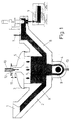
- Figure 1 is a vertical sectional view of the molding furnace already known with a superimposition of a practical realization of the object of the invention, which makes it easier to understand.
- a conventional oven consists of a tap hole (1) for the loading of metal, for example at 1430 ° C., already treated, for example, with ferro-silicon-magnesium, which descends through the loading nozzle (2) to the bucket (3) where an inductor (4) is provided which provides energy maintaining the casting at the desired temperature.
- the bucket (3) is closed by the cover (5) in which an inlet / outlet (11) of a pressurization gas (g), for example N 2, is made .
- a pressurization gas for example N 2
- salts tend to accumulate, for example magnesium silicates which impede circulation of casting and thermal transmission.
- the invention eliminates the inductor (9) with all its consequences and introduces one or more plasma torches as a fundamental element (10).
- the torch (10) is given a movement so that the plasma jet moves on said surface (s).
- the inert gas (N 2 , argon, etc.) used with the plasma can be the same as that of pressurization.
- the lighting of the torch (10) can be delayed as desired.
Description
Le chargement de moules sur les lignes automatiques de moulage se réalise principalement au moyen de fours de coulée pressurisés par un gaz inerte, et dotés de chauffage à induction électrique. Bien qu'il existe une grande variété de systèmes, ce type de fours présente une problématique commune, associée à la maintenance des inducteurs pour usure ou excroissance du réfractaire dans la zone de la bobine.Loading molds on automatic molding lines is mainly carried out by means of gas pressurized furnaces inert, and fitted with electric induction heating. Although there is great variety of systems, this type of oven presents a common problem, associated with the maintenance of inductors for wear or protrusion of the refractory in the coil area.
La fréquence et gravité de ces problèmes est portée à son point maximum dès lors qu'il s'agit de couler de la fonte nodulaire. Ce matériau comporte en effet la particularité d'incorporer dans sa composition une quantité déterminée de magnésium, lequel réagit avec certains éléments présents dans le réfractaire et le métal propre. Il se forme ainsi des composés à point de fusion élevé, lesquels adhèrent aux parois du réfractaire, spécialement aux points les plus chauds et de plus grande circulation de métal.The frequency and severity of these problems is brought to its point maximum when it comes to casting nodular cast iron. This material has the particularity of incorporating into its composition a quantity magnesium, which reacts with certain elements present in the refractory and clean metal. This produces compounds with a melting point. which adhere to the walls of the refractory, especially at the points hotter and greater metal circulation.
L'inducteur et ses zones adjacentes souffrent spécialement de ce problème, puisque que les conduits de chargement et de coulée en arrivent même à se boucher. Il faut alors procéder à un nettoyage exhaustif des tuyères et canaux de l'inducteur. Une telle opération est pénible, délicate et très laborieuse, puisqu'impliquant de surcroít le risque d'endommager le réfractaire qui protège l'inducteur.The inductor and its adjacent areas suffer specially from this problem, since the loading and pouring pipes even arrive to clog up. It is then necessary to carry out an exhaustive cleaning of the nozzles and channels of the inductor. Such an operation is painful, delicate and very laborious, since it also involves the risk of damaging the refractory that protects the inductor.
Par ailleurs, l'accouplement des inducteurs introduit un facteur de complexité dans le système qui empêche l'extinction du four, sinon en courant de gros risques. A cet effet, une fois mis en fonctionnement, on ne peut que le vider de métal pour procéder à la démolition du réfractaire et, dans le meilleur des cas, changer l'inducteur. Ce qui oblige à maintenir le chauffage connecté en permanence, ce qui suppose outre le problème cité auparavant, un important surcoût énergétique. Furthermore, the coupling of the inductors introduces a factor of complexity in the system which prevents the furnace from being switched off, otherwise by running big risks. For this purpose, once put into operation, we can only emptying of metal to demolish the refractory and, in the best cases, change the inductor. This requires keeping the heating connected in permanence, which supposes in addition to the problem mentioned above, an important additional energy cost.
Compte tenu que l'inducteur a pour unique fonction de conserver la coulée à peu près à la température de moulage, et face aux problèmes décrits, dont le demandeur a déduit qu'ils naissent de l'utilisation des inducteurs, il est proposé dans la présente demande de remplacer le chauffage à induction par un chauffage produit par un-plasma thermique à haute puissance. Le transfert thermique se produit dans ce cas au moyen de l'arc au plasma généré par le courant électrique et stabilisé avec le même gaz inerte (argon ou azote) qui peut être le même que celui utilisé pour pressuriser le four.Given that the inductor has the sole function of retaining casting at approximately the molding temperature, and faced with the problems described, which the applicant has deduced that they arise from the use of inductors, it is proposed in this application to replace the induction heating with a heating produced by a high-power thermal plasma. The transfer thermal occurs in this case by means of the plasma arc generated by the electric current and stabilized with the same inert gas (argon or nitrogen) which can be the same as that used to pressurize the oven.
Le brevet US 5 291 940 montre une benne de coulée dans laquelle l'apport énergétique à la masse liquide du métal se fait par une torche au plasma qui fonctionne à ciel ouvert, et qui agit directement sur le métal creant courants d'agitation qui originent pollution du point de vue metallurgique.US Patent 5,291,940 shows a tipping bucket in which the energetic contribution to the liquid mass of the metal is made by a plasma torch which operates in the open air, and which acts directly on the metal creating agitation currents which originate pollution from the point of view metallurgical.
La demande de l'invention montre un four de coulée dans lequel l'apport énergétique à la masse liquide du métal se fait par une torche à plasma, qui fonctionne en hotte fermée, avec du gaz sous pression, qui est à la fois plasmagène et inerte vis a vis du metal coulé (par exemple N2).The application of the invention shows a casting furnace in which the energy supply to the liquid mass of the metal is made by a plasma torch, which operates in a closed hood, with gas under pressure, which is both plasma-generating and inert with respect to cast metal (for example N 2 ).
Si on emploie l'azote comme gaz plasmagène, l'azote sous forme gazeuse (N2) se décompose en N plasmatique, qui apporte l'énergie au métal, ainsí l'action de la torche au plasma sur le métal est indirecte.If nitrogen is used as the plasma gas, nitrogen in gaseous form (N 2 ) breaks down into plasma N, which provides energy to the metal, so the action of the plasma torch on the metal is indirect.
La présence de N plasmatique sous pression induit la stabilisation de l'arc au plasma indispensable à la qualité de la fonte (sans pollution).The presence of plasma N under pressure induces stabilization of the plasma arc essential for the quality of the cast iron (without pollution).
Le four de coulée dispose aussi des moyens pour introduire et maintenir le gaz sous pression dans le four.The casting furnace also has means for introducing and keep the gas under pressure in the oven.
Il est prévu l'installation d'un système multiple de torches qui permette l'utilisation indistincte d'un arc transféré ou pas. L'application de l'un ou l'autre modèle dépendra du type de matériau que l'on prétendra couler. It is planned to install a multiple torch system which allows the indistinct use of a transferred or not transferred arc. The application of one or the other model will depend on the type of material that we pretend to pour.
L'introduction du plasma confère au four de coulée de
l'invention les particularités suivantes :
La présente invention préconise une four de coulée pour moulage automatique perfectionné, comportant notamment un trou de coulée-tuyère de chargement du métal en état de pré-inoculation, un gaz de pressurisation dans la benne et, pour le moins, une tuyère de coulée et de chargement du métal de moulage et se caractérisant par le fait qu'au dessus du niveau du métal dans la benne sont disposés dans le four de coulée, pour le moins, une torche à plasma thermique stabilisé de préférence en employant le même gaz que celui utilisé pour pressuriser le four et, au moins, une entrée/sortie de gaz, ledit ou lesdits gaz étant à la fois plasmagéne/s et inerte/s vis à vis du métal coulé.The present invention recommends a casting furnace for molding automatic improved, including in particular a pouring-nozzle hole of loading of the metal in the pre-inoculation state, a pressurization gas in the bucket and, at the very least, a metal pouring and loading nozzle molding and characterized by the fact that above the level of the metal in the grab are arranged in the casting furnace, at the very least, a plasma torch thermal stabilized preferably using the same gas as that used to pressurize the oven and at least one gas inlet / outlet, said gas or gases being both plasma / s and inert / s with respect to the cast metal.
La figure 1 est une vue en coupe en verticale du four de moulage déjà connu avec une superposition d'une réalisation pratique de l'objet de l'invention, qui en facilite la compréhension.Figure 1 is a vertical sectional view of the molding furnace already known with a superimposition of a practical realization of the object of the invention, which makes it easier to understand.
Un four conventionnel se compose d'un trou de coulée (1) pour le chargement de métal, par exemple à 1430°C, déjà traité, par exemple, au ferro-silicium-magnésium, qui descend par la tuyère de chargement (2) jusqu'à la benne (3) où se dispose inférieurement un inducteur (4) qui apporte de l'énergie en maintenant la coulée à la température souhaitée.A conventional oven consists of a tap hole (1) for the loading of metal, for example at 1430 ° C., already treated, for example, with ferro-silicon-magnesium, which descends through the loading nozzle (2) to the bucket (3) where an inductor (4) is provided which provides energy maintaining the casting at the desired temperature.
La benne (3) est fermée par le couvercle (5) dans lequel est pratiquée une entrée/sortie (11) d'un gaz (g) de pressurisation, par exemple N2.The bucket (3) is closed by the cover (5) in which an inlet / outlet (11) of a pressurization gas (g), for example N 2, is made .
Sous la pression du gaz de pressurisation, la coulée s'élève par la tuyère de coulée (6) vers les moules (7). Le tout dans une gaine de réfractaire.Under the pressure of the pressurizing gas, the flow rises by the pouring nozzle (6) to the molds (7). All in a refractory sheath.
A la jonction (8) de la tuyère de chargement (2) et de la benne (3), ainsi que dans les canaux (9) autour de l'inducteur (4), des sels tendent à s'accumuler, par exemple des silicates de magnésium qui entravent la circulation de la coulée et la transmission thermique.At the junction (8) of the loading nozzle (2) and the bucket (3), as well as in the channels (9) around the inductor (4), salts tend to accumulate, for example magnesium silicates which impede circulation of casting and thermal transmission.
L'invention élimine l'inducteur (9) avec toutes ses conséquences et introduit comme élément fondamental une ou plusieurs torche(s) au plasma (10).The invention eliminates the inductor (9) with all its consequences and introduces one or more plasma torches as a fundamental element (10).
Pour éviter des concentrations énergétiques à la surface (s) de la coulée dans la benne (3) on dote la torche (10) d'un mouvement de sorte que le jet de plasma se déplace sur ladite surface (s).To avoid energetic concentrations on the surface (s) of the poured into the bucket (3) the torch (10) is given a movement so that the plasma jet moves on said surface (s).
Le gaz inerte (N2, argon, etc.) utilisé avec le plasma peut être le même que celui de pressurisation.The inert gas (N 2 , argon, etc.) used with the plasma can be the same as that of pressurization.
Pour augmenter l'économie d'énergie on a prévu que lorsque le four, par exemple un lundi matin, sera froid, on préchauffera grâce à une lance thermique à oxycombustion, que cette phase peut remplacer physiquement la torche dans l'espace (10), c'est-à-dire, qui s'introduit par l'orifice supérieur (12).To increase energy saving, it was planned that when the oven, for example a Monday morning, will be cold, preheat with a lance thermal to oxycombustion, that this phase can physically replace the torch in space (10), that is to say, which is introduced through the upper orifice (12).
Le fonctionnement de l'unité en opération de coulée serait le
suivant
L'allumage de la torche (10) peut se temporiser à volonté.The lighting of the torch (10) can be delayed as desired.
La disposition et le nombre de torches au plasma (10), leur nature, par exemple à électrode de graphite (13), les orifices sur le couvercle (5), les entrées et sorties de gaz, peuvent être d'une sorte ou d'une autre, sans altérer pour autant l'invention telle que définie par les revendications jointes.The arrangement and number of plasma torches (10), their nature, for example with graphite electrode (13), the holes on the cover (5), gas inlets and outlets, may be of one kind or another, without altering provided the invention as defined by the appended claims.
Claims (5)
- Casting furnace for automatic moulding that includes, at least, one melting orifice-loading nozzle for metal in preoinculation state, a pressurisation gas in the vat and, at least, one casting and loading nozzle for moulding metal, which is characterised by the fact that on the level of the metal in the vat there is at least one thermal plasma torch in the casting furnace, stabilised preferably using the same gas as that used to pressurise the furnace, this gas or these gases being in turn plasmageneous and inert with respect to the cast metal and, at least, one gas input/output.
- Casting furnace for automatic moulding according to previous claim, which is characterised by the fact that the casting furnace has a thermal oxicombustion nozzle on the level of the metal in the vat.
- Casting furnace for automatic moulding, according to the previous claims, which is characterised by the fact that the energy jet from the plasma torch moves on the level of the metal.
- Casting furnace for automatic moulding according to previous claims, which is characterised by the fact that the plasma torch is placed on the top of the furnace.
- Automatic moulding procedure, which is characterised by the fact that in a moulding furnace described in claims 1, 2, 3 and 4, it is foreseen that, bearing in mind that the casting furnace is cold, it will be pre-heated with the thermal oxi-combustion fire slice to an appropriate temperature to receive the liquid metal, proceeding, if necessary later with the metal now in the furnace, to the temperature maintenance energy intake by means of the thermal plasma torch and also having the means to introduce and maintain the gas under pressure in the furnace.
Priority Applications (2)
| Application Number | Priority Date | Filing Date | Title |
|---|---|---|---|
| DE1997619035 DE69719035T2 (en) | 1997-11-18 | 1997-11-18 | Pouring furnace for automatic pouring |
| EP19970500195 EP0916435B1 (en) | 1997-11-18 | 1997-11-18 | Casting furnace for automatic molding |
Applications Claiming Priority (1)
| Application Number | Priority Date | Filing Date | Title |
|---|---|---|---|
| EP19970500195 EP0916435B1 (en) | 1997-11-18 | 1997-11-18 | Casting furnace for automatic molding |
Publications (2)
| Publication Number | Publication Date |
|---|---|
| EP0916435A1 EP0916435A1 (en) | 1999-05-19 |
| EP0916435B1 true EP0916435B1 (en) | 2003-02-12 |
Family
ID=8230100
Family Applications (1)
| Application Number | Title | Priority Date | Filing Date |
|---|---|---|---|
| EP19970500195 Expired - Lifetime EP0916435B1 (en) | 1997-11-18 | 1997-11-18 | Casting furnace for automatic molding |
Country Status (2)
| Country | Link |
|---|---|
| EP (1) | EP0916435B1 (en) |
| DE (1) | DE69719035T2 (en) |
Families Citing this family (2)
| Publication number | Priority date | Publication date | Assignee | Title |
|---|---|---|---|---|
| ES2168930B2 (en) * | 1999-12-23 | 2003-06-16 | Fundacion Inasmet | COLADA OVEN FOR MOLDING |
| CN112946013B (en) * | 2021-01-14 | 2022-10-04 | 永嘉工力科技有限公司 | Thermal analysis method for casting alloy |
Family Cites Families (4)
| Publication number | Priority date | Publication date | Assignee | Title |
|---|---|---|---|---|
| DE1288760B (en) * | 1966-06-14 | 1969-02-06 | Coupette | Method for controlling temperature and steel analysis during continuous casting and device for this |
| JPS59202142A (en) * | 1983-04-30 | 1984-11-15 | Nippon Steel Corp | Heating method of nozzle to be immersed into tundish |
| JPS62289363A (en) * | 1986-06-09 | 1987-12-16 | Kawasaki Steel Corp | Pressurization type pouring furnace |
| US5291940A (en) * | 1991-09-13 | 1994-03-08 | Axel Johnson Metals, Inc. | Static vacuum casting of ingots |
-
1997
- 1997-11-18 EP EP19970500195 patent/EP0916435B1/en not_active Expired - Lifetime
- 1997-11-18 DE DE1997619035 patent/DE69719035T2/en not_active Expired - Fee Related
Also Published As
| Publication number | Publication date |
|---|---|
| DE69719035T2 (en) | 2003-12-04 |
| EP0916435A1 (en) | 1999-05-19 |
| DE69719035D1 (en) | 2003-03-20 |
Similar Documents
| Publication | Publication Date | Title |
|---|---|---|
| EP0647598B1 (en) | Method for burning and vitrifying of waste in a pot | |
| FR2772741A1 (en) | Silicon refining process for industrial mass production of photovoltaic cell grade silicon | |
| EP0916435B1 (en) | Casting furnace for automatic molding | |
| EP0875319B1 (en) | Tundish provided with at least one plasma torch for reheating molten metal | |
| EP0649477B1 (en) | Electric furnace for melting scrap iron | |
| FR2582972A1 (en) | CASH POCKET | |
| EP0626549A1 (en) | Metallurgical smelting furnace such as a steelplant electric furnace and process using such a furnace | |
| FR2591135A1 (en) | IMPROVED METHOD OF ADJUSTING CONTINUOUS CASTING CONDITIONS. | |
| WO1995016796A1 (en) | Loading device for feeding liquid metal into an electric furnace | |
| EP0349405B1 (en) | Process and installation for the microwave melting of a material corrosive at an elevated temperature | |
| FR2767081A1 (en) | PROCESS FOR HEATING A LIQUID METAL IN A CONTINUOUS CASTING DISTRIBUTOR USING A PLASMA TORCH, AND DISTRIBUTOR FOR IMPLEMENTING SAME | |
| EP1258303B1 (en) | Novel smelting furnace for molding | |
| EP0468832B1 (en) | Furnace for holding the temperature and for metallurgical treatment | |
| EP0028569B1 (en) | Process for agitating a molten metal by injection of gases | |
| FR2666816A1 (en) | ROTARY FURNACE FOUNDRY INSTALLATION AND OPERATING METHOD. | |
| CA2204137C (en) | Liquid metal heating and casting ladle | |
| FR2658277A1 (en) | METALLURGICAL CONTAINER EQUIPPED WITH AT LEAST ONE ELECTRODE CROSSING ITS WALL. | |
| FR2550326A1 (en) | METHOD AND DEVICE FOR HEATING GAS USING ANOTHER GAS | |
| FR2693135A1 (en) | Continuous casting installation between moving walls, and casting method using the installation. | |
| BE1004483A3 (en) | Heating method for bath liquid steel. | |
| FR2852608A1 (en) | Recuperation of zinc contained in molten iron by vacuum treatment and collection of zinc dust, allowing the use of some zinc coated steel scrap in the iron-making operation | |
| FR2632056A1 (en) | Method and device for protecting heat exchanger tubes against rust | |
| FR2691240A1 (en) | Electric furnace for prodn. of metal e.g. steel - comprising vat limited by lateral wall surrounding bottom covered by sill of refractory material forming crucible | |
| BE435128A (en) | ||
| FR2667877A1 (en) | PROCESS FOR RECOVERING PLATINOUIDS DEPOSITED IN THIN FILMS ON A CERAMIC SUBSTRATE FROM A USED CATALYST. |
Legal Events
| Date | Code | Title | Description |
|---|---|---|---|
| PUAI | Public reference made under article 153(3) epc to a published international application that has entered the european phase |
Free format text: ORIGINAL CODE: 0009012 |
|
| AK | Designated contracting states |
Kind code of ref document: A1 Designated state(s): BE DE DK FR GB GR IT NL PT SE |
|
| AX | Request for extension of the european patent |
Free format text: AL;LT;LV;MK;RO;SI |
|
| 17P | Request for examination filed |
Effective date: 19991105 |
|
| AKX | Designation fees paid |
Free format text: BE DE DK FR GB GR IT NL PT SE |
|
| 17Q | First examination report despatched |
Effective date: 20010419 |
|
| GRAG | Despatch of communication of intention to grant |
Free format text: ORIGINAL CODE: EPIDOS AGRA |
|
| GRAG | Despatch of communication of intention to grant |
Free format text: ORIGINAL CODE: EPIDOS AGRA |
|
| GRAH | Despatch of communication of intention to grant a patent |
Free format text: ORIGINAL CODE: EPIDOS IGRA |
|
| GRAH | Despatch of communication of intention to grant a patent |
Free format text: ORIGINAL CODE: EPIDOS IGRA |
|
| GRAA | (expected) grant |
Free format text: ORIGINAL CODE: 0009210 |
|
| AK | Designated contracting states |
Designated state(s): BE DE DK FR GB GR IT NL PT SE |
|
| PG25 | Lapsed in a contracting state [announced via postgrant information from national office to epo] |
Ref country code: NL Free format text: LAPSE BECAUSE OF FAILURE TO SUBMIT A TRANSLATION OF THE DESCRIPTION OR TO PAY THE FEE WITHIN THE PRESCRIBED TIME-LIMIT Effective date: 20030212 Ref country code: GR Free format text: LAPSE BECAUSE OF FAILURE TO SUBMIT A TRANSLATION OF THE DESCRIPTION OR TO PAY THE FEE WITHIN THE PRESCRIBED TIME-LIMIT Effective date: 20030212 |
|
| REG | Reference to a national code |
Ref country code: GB Ref legal event code: FG4D Free format text: NOT ENGLISH |
|
| REF | Corresponds to: |
Ref document number: 69719035 Country of ref document: DE Date of ref document: 20030320 Kind code of ref document: P |
|
| PG25 | Lapsed in a contracting state [announced via postgrant information from national office to epo] |
Ref country code: PT Free format text: LAPSE BECAUSE OF FAILURE TO SUBMIT A TRANSLATION OF THE DESCRIPTION OR TO PAY THE FEE WITHIN THE PRESCRIBED TIME-LIMIT Effective date: 20030512 Ref country code: DK Free format text: LAPSE BECAUSE OF FAILURE TO SUBMIT A TRANSLATION OF THE DESCRIPTION OR TO PAY THE FEE WITHIN THE PRESCRIBED TIME-LIMIT Effective date: 20030512 |
|
| REG | Reference to a national code |
Ref country code: SE Ref legal event code: TRGR |
|
| GBT | Gb: translation of ep patent filed (gb section 77(6)(a)/1977) | ||
| NLV1 | Nl: lapsed or annulled due to failure to fulfill the requirements of art. 29p and 29m of the patents act | ||
| PGFP | Annual fee paid to national office [announced via postgrant information from national office to epo] |
Ref country code: SE Payment date: 20031105 Year of fee payment: 7 |
|
| PGFP | Annual fee paid to national office [announced via postgrant information from national office to epo] |
Ref country code: FR Payment date: 20031110 Year of fee payment: 7 |
|
| PGFP | Annual fee paid to national office [announced via postgrant information from national office to epo] |
Ref country code: GB Payment date: 20031112 Year of fee payment: 7 |
|
| PGFP | Annual fee paid to national office [announced via postgrant information from national office to epo] |
Ref country code: DE Payment date: 20031127 Year of fee payment: 7 |
|
| PG25 | Lapsed in a contracting state [announced via postgrant information from national office to epo] |
Ref country code: BE Free format text: LAPSE BECAUSE OF NON-PAYMENT OF DUE FEES Effective date: 20031130 |
|
| PLBE | No opposition filed within time limit |
Free format text: ORIGINAL CODE: 0009261 |
|
| STAA | Information on the status of an ep patent application or granted ep patent |
Free format text: STATUS: NO OPPOSITION FILED WITHIN TIME LIMIT |
|
| 26N | No opposition filed |
Effective date: 20031113 |
|
| BERE | Be: lapsed |
Owner name: *FUNDACION INASMET Effective date: 20031130 |
|
| PG25 | Lapsed in a contracting state [announced via postgrant information from national office to epo] |
Ref country code: GB Free format text: LAPSE BECAUSE OF NON-PAYMENT OF DUE FEES Effective date: 20041118 |
|
| PG25 | Lapsed in a contracting state [announced via postgrant information from national office to epo] |
Ref country code: SE Free format text: LAPSE BECAUSE OF NON-PAYMENT OF DUE FEES Effective date: 20041119 |
|
| PG25 | Lapsed in a contracting state [announced via postgrant information from national office to epo] |
Ref country code: DE Free format text: LAPSE BECAUSE OF NON-PAYMENT OF DUE FEES Effective date: 20050601 |
|
| EUG | Se: european patent has lapsed | ||
| GBPC | Gb: european patent ceased through non-payment of renewal fee |
Effective date: 20041118 |
|
| PG25 | Lapsed in a contracting state [announced via postgrant information from national office to epo] |
Ref country code: FR Free format text: LAPSE BECAUSE OF NON-PAYMENT OF DUE FEES Effective date: 20050729 |
|
| REG | Reference to a national code |
Ref country code: FR Ref legal event code: ST |
|
| PG25 | Lapsed in a contracting state [announced via postgrant information from national office to epo] |
Ref country code: IT Free format text: LAPSE BECAUSE OF NON-PAYMENT OF DUE FEES Effective date: 20051118 |