EP0916219B1 - Server and method for automatically delivering messages to a telecommunications device - Google Patents
Server and method for automatically delivering messages to a telecommunications device Download PDFInfo
- Publication number
- EP0916219B1 EP0916219B1 EP98918445A EP98918445A EP0916219B1 EP 0916219 B1 EP0916219 B1 EP 0916219B1 EP 98918445 A EP98918445 A EP 98918445A EP 98918445 A EP98918445 A EP 98918445A EP 0916219 B1 EP0916219 B1 EP 0916219B1
- Authority
- EP
- European Patent Office
- Prior art keywords
- subscriber
- message
- caller
- information
- format
- Prior art date
- Legal status (The legal status is an assumption and is not a legal conclusion. Google has not performed a legal analysis and makes no representation as to the accuracy of the status listed.)
- Expired - Lifetime
Links
Images


Classifications
-
- H—ELECTRICITY
- H04—ELECTRIC COMMUNICATION TECHNIQUE
- H04L—TRANSMISSION OF DIGITAL INFORMATION, e.g. TELEGRAPHIC COMMUNICATION
- H04L51/00—User-to-user messaging in packet-switching networks, transmitted according to store-and-forward or real-time protocols, e.g. e-mail
- H04L51/06—Message adaptation to terminal or network requirements
- H04L51/066—Format adaptation, e.g. format conversion or compression
-
- H—ELECTRICITY
- H04—ELECTRIC COMMUNICATION TECHNIQUE
- H04M—TELEPHONIC COMMUNICATION
- H04M3/00—Automatic or semi-automatic exchanges
- H04M3/42—Systems providing special services or facilities to subscribers
- H04M3/50—Centralised arrangements for answering calls; Centralised arrangements for recording messages for absent or busy subscribers ; Centralised arrangements for recording messages
- H04M3/53—Centralised arrangements for recording incoming messages, i.e. mailbox systems
- H04M3/5307—Centralised arrangements for recording incoming messages, i.e. mailbox systems for recording messages comprising any combination of audio and non-audio components
-
- H—ELECTRICITY
- H04—ELECTRIC COMMUNICATION TECHNIQUE
- H04L—TRANSMISSION OF DIGITAL INFORMATION, e.g. TELEGRAPHIC COMMUNICATION
- H04L51/00—User-to-user messaging in packet-switching networks, transmitted according to store-and-forward or real-time protocols, e.g. e-mail
- H04L51/21—Monitoring or handling of messages
- H04L51/224—Monitoring or handling of messages providing notification on incoming messages, e.g. pushed notifications of received messages
-
- H—ELECTRICITY
- H04—ELECTRIC COMMUNICATION TECHNIQUE
- H04M—TELEPHONIC COMMUNICATION
- H04M2201/00—Electronic components, circuits, software, systems or apparatus used in telephone systems
- H04M2201/60—Medium conversion
-
- H—ELECTRICITY
- H04—ELECTRIC COMMUNICATION TECHNIQUE
- H04M—TELEPHONIC COMMUNICATION
- H04M7/00—Arrangements for interconnection between switching centres
- H04M7/12—Arrangements for interconnection between switching centres for working between exchanges having different types of switching equipment, e.g. power-driven and step by step or decimal and non-decimal
-
- H—ELECTRICITY
- H04—ELECTRIC COMMUNICATION TECHNIQUE
- H04W—WIRELESS COMMUNICATION NETWORKS
- H04W4/00—Services specially adapted for wireless communication networks; Facilities therefor
- H04W4/12—Messaging; Mailboxes; Announcements
Definitions
- the present invention relates generally to messaging systems and more particularly to a universal messaging center or mailbox that notifies subscribers of any type of message that is waiting for them, for example, voice mail, fax mail, e-mail, etc., and allows subscribers to retrieve and respond to the messages in formats independent not only of each other but also of the format in which the message was originally transmitted.
- the present invention further relates to a messaging system and method that automatically transfer messages for display on subscriber equipment.
- messaging services might include voice messaging, facsimile messaging, electronic mail, electronic document interchange, interactive voice response, audio text, speech synthesis, speech recognition, video messaging, video mail, etc.
- the messaging center performs protocol conversions between the format employed by the messaging center and the various telecommunications formats employed by the diverse subscriber equipment.
- U.S. Patent No. 5,497,373 to Hulen et al. describes a system with a host messaging center that supports numerous types of messaging applications and makes the necessary protocol conversions for different telecommunications protocols corresponding to various types of telecommunications media.
- the system uses multiple digital signal processors to perform real time protocol conversions between the different telecommunication protocols and the protocol of the host messaging center.
- Fig. 1 is a block diagram showing how Hulen et al. 's messaging system might connect to multimedia subscribers through various public and private communications networks 110, including, for example, the public switched telephone network (PSTN), a public cellular or mobile telephone network (PLMN), and a packet switched public data network (PSPDN).
- PSTN public switched telephone network
- PLMN public cellular or mobile telephone network
- PSPDN packet switched public data network
- the messaging system includes telephony front end equipment 120, multimedia interface 130, and host messaging center 140.
- Telephony front end 120 interfaces to communications networks 110 and provides the necessary interface between a subscriber's voice or data channel from communications network 110 and the messaging system.
- Multimedia interface 130 performs protocol conversions of the information received in various telecommunications formats so host messaging center 140 can process and store the information in the host's data processing and storage format, typically a compressed data format.
- host messaging center 140 processes the relevant messaging information extracted from the communications channel to deliver the particular messaging or telephony service requested by the subscriber.
- Multimedia interface 130 then converts the information for responding to the subscriber's service request back into the communications protocol format used by the subscriber, and transmits the converted information to the subscriber via telephony front end 120 and communications network 110.
- Multimedia interface 130 includes several parallel digital signal processors dynamically allocated to handle different types of protocol conversion for multiple communications channels.
- Host messaging center 140 downloads appropriate protocol conversion algorithms to selected digital signal processors depending upon the type of services required by a particular subscriber.
- the selected digital signal processors convert and store the information in the format of host messaging center 140 so host messaging center 140 can process the information according to the particular messaging services requested by the subscriber.
- the subscriber retrieves the information in the communications protocol format used by the subscriber.
- Patent WO 87/07801 describes an alternative system where the network has a unified messaging system (UMS) to provide the access point for all messages regardless of the message format/origination.
- UMS unified messaging system
- the user can then access the UMS mailbox using any terminal type.
- the user can also designate a receptor through which the user can be alerted to a received message. However, once alerted to the message the user still has to enter the receptor service using a set of message retrieval commands.
- a server as recited in Claim 1.
- a method for automatically transferring information to subscriber as recited in Claim 10.
- the present invention provides a server in a telecommunications network comprising means for receiving information intended for a subscriber from a caller in a caller format; means for translating the information to a subscriber format compatible with equipment of the subscriber; and means for automatically transferring the translated information to the subscriber equipment independent of any action by the subscriber.
- a universal mailbox is provided by which a subscriber can retrieve a pending message in a format independent of the format used to store the message, and respond to the message in a format independent of the format used to store or retrieve the message.
- the present invention provides a system and method that automatically translate messages to a format used by a subscriber's telecommunications equipment and deliver the translated messages to the subscriber's telecommunications equipment independent of any action by the subscriber.
- the universal mailbox processes messages intended for a subscriber.
- a taller sends a message to the message center in a first caller format.
- the message center stores the message in the first caller format, notifies the subscriber, and awaits a request for the stored message from the subscriber.
- the message center sends the stored message to the subscriber in a first subscriber format independent of the first caller format.
- the subscriber constructs a response to the message and sends it to the message center in a second subscriber format independent of the first caller format and the first subscriber format.
- the message center stores the response in the second subscriber format and sends the stored response to the caller in a second caller format independent of the first caller format and the first and second subscriber formats.
- the system comprises a receiving element, a translating element, and a routing element.
- the receiving element receives messages intended for subscriber equipment from caller equipment in caller formats.
- the translating element translates the messages to a subscriber format compatible with the subscriber equipment.
- the routing element automatically transfers the translated messages to the subscriber equipment without requiring the subscriber to initiate the message transfer.
- subscriber refers to a person that subscribes to the services provided by the systems and methods consistent with the present invention.
- the subscriber can store messages for other subscribers or retrieve messages that have been left for the subscriber.
- Systems and methods in an implementation consistent with the present invention permit subscribers to retrieve and respond to any type of stored message in whatever format the subscribers desire.
- Systems and methods in another implementation consistent with the present invention receive messages intended for subscribers, translate the messages to a form compatible with the subscribers' telecommunications equipment, and automatically transfer the messages to the subscribers' telecommunications equipment without requiring that the subscribers initiate the transfer process.
- Fig. 2 is a block diagram of an exemplary communications network containing the universal mailbox of the present invention.
- Subscribers of the universal mailbox service connect to the network via a variety of telecommunications equipment through analog, digital, and Internet lines, and wireless connections.
- the subscriber equipment includes, but is not limited to, group 1, 2, 3 facsimile machine 211, Plain Old Telephone System (POTS) telephone 212, Analog Display Services Interface (ADSI) telephone 213, group 4 facsimile machine 214, ISDN telephone 215, computer terminal 216, Personal Communications Services (PCS) wireless telephone 217, PCS mobile telephone 218, and analog/digital cellular telephone 219.
- ADSI telephone 213 might include group 3 facsimile machine 213-2 and printer 213-4 connected thereto.
- End offices 220 connect the subscriber equipment, except for Internet terminal 216, to the network.
- Group 1, 2, 3 facsimile machine 211, POTS telephone 212, and ADSI telephone 213 connect to end offices 220 over conventional analog lines.
- Group 4 facsimile machine 214 and ISDN telephone 215 connect over conventional digital lines.
- PCS wireless telephone 217, PCS mobile telephone 218, and analog/digital cellular telephone 219 connect to end offices 220 via conventional wireless connections.
- End office 220 connects to universal mailbox 230 by conventional mechanisms over a Public Telecommunications Network (PTN), such as the Public Switched Telephone Network (PSTN).
- PTN Public Telecommunications Network
- PSTN Public Switched Telephone Network
- Internet terminal 216 connects to universal mailbox 230 by conventional mechanisms over the Internet.
- Universal mailbox 230 includes a computer with conventional connections to the PTN and the Internet, and might include a UNIX-capable computer, such as an HP model or the IBM Risc 6000.
- Fig. 3 is a block diagram of the elements of universal mailbox 230.
- Universal mailbox 230 preferably includes interface 310, service provider 320, subscriber mailbox 330, and message translator 340.
- Interface 310 connects universal mailbox 230 to various telecommunications networks, including the PTN and the Internet.
- Fig. 4 is a block diagram of the elements of interface 310, including transceivers 410, detectors 420, and selectors 430.
- Transceivers 410 interface with the various networks, including the PTN and the Internet, and exchange signals with the subscriber equipment to permit subscribers to store, retrieve, and respond to messages in universal mailbox 230, and to permit universal mailbox 230 to notify the subscribers of pending messages awaiting retrieval.
- Detectors 420 which preferably include conventional signal line detectors, detect the type of telecommunications equipment a subscriber is using based upon the types of signals received by transceivers 410. Detectors 420 send information indicating the equipment type to message translator 340 and a selection signal to selectors 430.
- Selectors 430 which include conventional selectors, such as multiplexers/demultiplexers, route the subscriber signals received by transceivers 410 to service provider 320 using the selection signal from detectors 420, and also route notification signals to the subscribers via transceivers 410.
- service provider 320 connects to interface 310, subscriber mailbox 330. and message translator 340, and provides subscriber services in the various forms as the subscribers require.
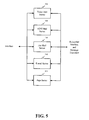
- Fig. 5 is a block diagram of possible elements of service provider 320, including voice mail server 510, ADSI mail server 520, fax mail server 530, e-mail server 540, and page server 550.
- Voice mail server 510 provides voice mail services for a subscriber, including the storage and retrieval of voice messages in subscriber mailbox 330. Upon receipt of a voice call, voice mail server 510 detects information regarding the caller, such as calling line identification (CLID) data, from the voice call signal by conventional mechanisms, and stores the caller information along with the voice message in subscriber mailbox 330.
- CLID calling line identification
- ADSI mail server 520 provides ADSI mail services for the subscriber, including the storage and retrieval of voice, ADSI text, and mixed voice and ADSI text messages in subscriber mailbox 330.
- ADSI mail server 520 Upon receipt of ADSI mail, ADSI mail server 520 detects the caller information from the ADSI mail signal, as described above, and stores the caller information along with the ADSI mail in subscriber 330.
- Fax mail server 530, e-mail server 540, and page server 550 store and retrieve fax, e-mail, and page messages, respectively, for the subscriber in the same manner set forth above.
- servers 510 through 550 also notify the subscribers of pending messages in subscriber mailbox 330 that await retrieval.
- Table 1 shows examples of various forms of subscriber notification based upon the type of telecommunications equipment the subscriber uses to retrieve the pending messages.
- TABLE 1 RETRIEVAL DEVICE POTS Phone ADSI Phone Pager Fax Computer NOTIFICATION TYPES >Phone call >Phone call >Deliver the message. >Deliver the message. >Audible or visual alert on screen >Message waiting light >Message waiting light >Message waiting tone. >Message waiting tone >Deliver the message. >Display message information on screen >Download message to phone (for non-voice messages).
- subscriber mailbox 330 preferably includes a large-capacity memory device, such as a disk array, with connections to service provider 320 and message translator 340. Subscriber mailbox 330 stores subscriber messages in the different subscriber formats. The particular formats of a pending stored message might include the format used by the caller or the subscriber leaving the message and the format typically requested by the subscriber, as described below. Subscriber mailbox 330 preferably stores the pending messages in both of these formats.
- Subscriber mailbox 330 preferably also stores a database of subscriber profile data.
- the subscriber profile data includes subscriber-defined information regarding the subscriber's notification preferences.
- the subscriber profile data might include any of the notification types shown in Table 1, including notifying the subscriber using a message waiting light or tone, or by sending part or all of the message to the subscriber as the notification.
- the subscriber profile data could be more specific.
- the subscriber might associate a notification type with a specific type of telecommunications equipment.
- the subscriber could designate notification by an ADSI text message when retrieving messages using ADSI phone 213.
- Message translator 340 connects to subscriber mailbox 330, interface 310, and service provider 320, and performs translations between the various subscriber message formats.
- Fig. 6 is a block diagram of the elements of message translator 340, including controller 610, plain telephone translator 620, fax machine translator 630, ADSI telephone translator 640, computer translator 650, pager translator 660, and miscellaneous translator 670.
- Controller 610 preferably includes a standard processor that controls the operation of translators 620 through 670. For each message retrieval, controller 610 records the type of telecommunications equipment the subscriber uses based on the subscriber equipment detected by detectors 420 of interface 310. From the recorded equipment type, controller 610 determines a normal retrieval format for each subscriber. If a subscriber typically retrieves pending messages using POTS telephone 212, for example, controller 610 records the subscriber's normal retrieval format as a voice format. Controller 610 stores the subscriber's normal retrieval format in subscriber mailbox 330.
- controller 610 retrieves the pending messages from subscriber mailbox 330, translates them from the stored format to the normal retrieval format using one of the translators 620 through 670, and returns the translated messages to subscriber mailbox 330.
- Translators 620 through 670 execute conventional translation techniques, such as described in U.S. Patent No. 5,497,373 to Hulen et al. , to perform translations from the stored format to the subscriber's normal retrieval format.
- Table 2 shows examples of various translations performed by translators 620 through 670. TABLE 2 RETRIEVAL DEVICE POTS Phone ADSI Phone Fax Computer Pager TRANSLATOR Plain telephone None. Message information can be provided in ADSI text format.
- Voice to ADSI text used for hearing impaired service Voice to text to Fax graphics, and Message information. Voice to sound file (and to text for hearing impaired), and message information. Message information only. Fax machine Fax graphics to text to voice. Fax graphics to ADSI text. None. Fax graphics to computer graphics, and message information. Message information only. ADSI telephone None for voice. ADSI text to voice. None. ADSI text to Fax graphics. ADSI text to text. Message information only. Computer Text to voice. Text to ADSI text. Text to Fax graphics. None. Message information only. Pager Text to voice. Text to ADSI text. Text to Fax graphics. None. None. None.
- Figs. 7-9 are flowcharts illustrating the operation of the universal mailbox consistent with the principles of the present invention.
- Fig. 7 is a flowchart of a process for storing a message in universal mailbox 230. The process begins when a caller sends a message to a subscriber in a caller format. The caller format depends upon the type of telecommunications equipment the caller utilizes to send the message.
- the caller may send the message to universal mailbox 230 or to the subscriber's telecommunications equipment.
- the subscriber's telecommunications equipment would then relay the message to universal mailbox 230 by conventional mechanisms, when the subscriber is unavailable to receive the message.
- interface 310 in universal mailbox 230 receives the message from the caller in the caller format [step 710], and forwards it to service provider 320.
- Service provider 320 analyzes the message to detect information regarding the caller from the message signal, as described above.
- Service provider 320 then stores the message in subscriber mailbox 330 in the caller format along with the detected caller information [step 720], and notifies the subscriber of the pending message [step 730].
- Service provider 320 notifies the subscriber according to the subscriber profile data stored in subscriber mailbox 330.
- the subscriber notification may include a message waiting light or tone on the subscriber's telephone, or the message itself delivered to the subscriber's ADSI telephone, pager, fax, or computer (Table 1).
- message translator 340 determines the subscriber's normal retrieval format from the information stored in subscriber mailbox 330 [step 740]. When the caller format differs from the subscriber's normal retrieval format, message translator 340 translates the message from the caller format to the subscriber's normal retrieval format [step 750]. Message translator 340 then stores the message in subscriber mailbox 330 in the subscriber's normal retrieval format [step 760], preferably without erasing the message in the caller format. As a result, subscriber mailbox 330 stores the message in both the caller format and the subscriber's normal retrieval format.
- the subscriber When the subscriber wants to retrieve a pending message, the process shown by the flowchart in Fig. 8 occurs.
- the subscriber establishes a connection between the subscriber's telecommunications equipment and universal mailbox 230 to request retrieval of the pending message.
- the subscriber might accomplish this by dialing universal mailbox 230's telephone number, or by configuring the subscriber's telecommunications equipment to automatically establish the connection.
- Interface 310 of universal mailbox 230 receives the subscriber's request for retrieval of the pending message [step 810], and detects the type of telecommunications equipment the subscriber used to make the request [step 820]. Because some types of telecommunications equipment permit the subscriber to retrieve the pending message in more than one form, the subscriber must specify the desired retrieval form when using these types of telecommunications equipment. For example, if the subscriber uses ADSI telephone 213 to retrieve the pending message, the subscriber must specify whether the pending message should be downloaded in voice or ADSI text form.
- Interface 310 then routes the request to service provider 320.
- service provider 320 determines the subscriber's retrieval format [step 830].
- Service provider 320 reads the pending message from subscriber mailbox 330 and determines whether the message is already in the retrieval format [step 840]. The message would already be in the retrieval format if the retrieval format is the same as the caller format or the subscriber's normal retrieval format. If the message is already in the retrieval format, then service provider 320 sends the message to the subscriber [step 850].
- service provider 320 If the message is not already in the retrieval format, service provider 320 notifies message translator 340.
- Message translator 340 reads the message from subscriber mailbox 330 and translates the message to the retrieval format [step 860]. After translation, message translator 340 gives the message to service provider 320. Service provider 320, in turn, sends the message to the subscriber in the retrieval format [step 870].
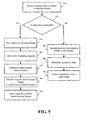
- the subscriber determines what form the response will take, the process shown by the flowchart in Fig. 9 occurs.
- the subscriber generates a response for the caller and sends it to universal mailbox 230.
- Interface 310 receives the response from the subscriber in the response format [step 910], and forwards it to service provider 320.
- the response format may differ from both the caller format and the retrieval format.
- service provider 320 Upon receipt of the response, service provider 320 determines whether the caller is also a subscriber to the universal mailbox services by checking for the caller's identity in subscriber mailbox 330 [step 920]. If the caller is a subscriber, service provider 320 stores the response in subscriber mailbox 330 in the response format [step 930], and notifies the caller of the pending response, in the manner described above [step 940].
- message translator 340 determines the caller's normal retrieval format from the information stored in subscriber mailbox 330 [step 950]. When the response format differs from the caller's normal retrieval format, message translator 340 translates the response from the response format to the caller's normal retrieval format [step 960]. Message translator 340 then stores the response in the caller's normal retrieval format in subscriber mailbox 330 [step 970].
- service provider 320 If the caller is not also a subscriber, service provider 320 notifies message translator 340 to translate the response to the caller format, the same format as the original message sent by the caller [step 980]. After translating the response, message translator 340 returns it to service provider 320. Service provider then determines the location of the caller, including the caller's e-mail address, telephone number, or fax number, from the caller information stored in subscriber mailbox 330 [step 990]. Alternatively, service provider 320 could obtain the caller's location from the subscriber. Service provider 320 might obtain the caller's location from the subscriber when the caller information would not direct the response to the caller's correct location, for example, when the caller originally sent the message from public telecommunications equipment.
- service provider 320 transmits the response to the caller in the caller format [step 995]. This transmission might take the form of a telephone call, a fax, an e-mail, or a page to the caller.
- Tables 1 through 3 show types of notification, translators, and responses, respectively, corresponding to various types of telecommunications equipment. These were presented as examples only and would obviously include other types of notification, translators, responses, and telecommunications equipment, taking advantage of new advancements in the art, as well as the development of new types of telecommunications equipment.
- the subscriber has been described as responding to a retrieved message using the same telecommunications equipment used to retrieve the message. This need not be the case, however.
- the universal mailbox consistent with the principles of the present invention permits a subscriber to respond to a pending message using a different type of telecommunications equipment than was used to retrieve the message without requiring the subscriber to retrieve the message a second time.
- the subscriber need only record the reference number associated with the retrieved message to inform the universal mailbox of the identity of the message to which the subscriber subsequently responds.
- Fig. 10 is a block diagram of communications network 1000 in another implementation consistent with the principles of the present invention.
- a subscriber using, for example, ADSI telephone 1100 receives messages from callers using different types of telecommunications equipment.
- the caller telecommunications equipment might include group 1, 2, 3, or 4 facsimile machine 1210, POTS or ISDN telephone 1220, Global System for Mobile Communications (GSM) mobile unit 1230, and Internet terminal 1240.
- GSM Global System for Mobile Communications
- Fig. 11 is a block diagram of ADSI telephone 1100, which includes processor 2100, memory 2200, input/output interface 2300, display 2400, keys 2500, and telephone handset 2600.
- Processor 2100 is a standard microprocessor that controls operation of ADSI telephone 1100, including the processing of incoming voice calls and text messages.
- Memory 2200 is a conventional memory device, such as a RAM, that stores incoming voice and text messages.
- Input/output interface 2300 connects processor 2100 to input and output devices, such as display 2400, keys 2500, and telephone handset 2600.
- Display 2400 is a conventional flat screen display, such as an LCD display, that displays information to the subscriber.
- Keys 2500 include several function keys and regular telephone alphanumeric keys to permit the subscriber to input information and dial telephone numbers.
- Telephone handset 2600 is a conventional telephone handset that permits the subscriber to make and receive voice calls.
- end offices 1310 and 1320 connect the subscriber and caller telecommunications equipment, except for Internet terminal 1240, to network 1000.
- ADSI telephone 1100, group 1, 2, 3 facsimile machine 1210, and POTS telephone 1220 connect to end offices 1310 and 1320 over conventional analog lines.
- Group 4 facsimile machine 1210 and ISDN telephone 1220 connect over conventional digital lines.
- GSM mobile unit 1230 connects to end offices 1320 via a GSM network.
- End offices 1310 and 1320 are standard Private Branch Exchanges (PBXs) or Class 5 telephone switches that connect to ADSI server 1400 by conventional mechanisms over a public voice network, such as the PSTN.
- PBXs Private Branch Exchanges
- Internet terminal 1240 connects to ADSI server 1400 by conventional mechanisms over a data network, such as the Internet.
- ADSI server 1400 includes a computer with conventional connections to various telecommunications networks, such as the PSTN and the Internet, and might include a UNIX-capable computer, such as an HP model or the IBM Rise 6000.
- ADSI server 1400 translates messages from the callers and presents the translated messages to the subscribers' telecommunications equipment.
- FIG. 12 is a block diagram of elements of ADSI server 1400 consistent with the principles of the present invention.
- ADSI server 1400 preferably includes interface 3100 and ADSI translator 3200.
- Interface 3100 connects ADSI server 1400 to various telecommunications networks, including the PSTN and the Internet.
- Fig. 13 is a block diagram of elements of interface 3100, including transceiver 4100, detector 4200, and selector 4300. While Fig. 13 shows only a single transceiver, detector, and selector, interface 3100 actually includes several of these elements for concurrently handling messages from several different callers.
- Transceiver 4100 interfaces with the various networks, including the PSTN and the Internet, and exchanges signals with the subscribers' and callers' telecommunications equipment to permit callers to transmit messages to ADSI server 1400, and to permit ADSI server 1400 to forward these messages to the subscribers' telecommunications equipment.
- Detector 4200 which preferably includes a conventional signal line detector, detects the type of telecommunications equipment a caller uses based on the type of signal received by transceiver 4100. Detector 4200 sends information indicating the equipment type as a selection signal to selector 4300.
- Selector 4300 which includes a conventional selector such as a multiplexer/demultiplexer, routes the caller signals received by transceiver 4100 to ADSI translator 3200 using the selection signal from detector 4200. Selector 4300 also routes messages to the subscribers via transceiver 4100.
- a conventional selector such as a multiplexer/demultiplexer
- ADSI translator 3200 connects to interface 3100 and performs message translations from the formats used by the callers' telecommunications equipment to the format compatible with the subscribers' telecommunications equipment, or the ADSI text format, according to the implementation shown in Fig. 10.
- Fig. 14 is a block diagram of ADSI translator 3200, including voice translator 5100, fax graphics translator 5200, text translator 5300, and miscellaneous translator 5400.
- Voice translator 5100 includes controller 5120 and several voice translation units 5150 that translate voice messages to ADSI text format.
- controller 5120 Upon receipt of a voice call, controller 5120 detects information regarding the caller, such as calling line identification (CLID) data, from the voice call signal by conventional mechanisms, and records the voice message. Controller 5120 then selects one of the voice translation units 5150 to translate the voice message to ADSI text format. The selected voice translation unit 5150 can use conventional translation software to perform this translation.
- CLID calling line identification
- controller 5120 When the selected voice translation unit 5150 finishes translating the voice message, controller 5120 generates an ADSI text message including the caller information and the translated voice message. Controller 5120 then sends the ADSI text message to interface 3100 for routing to the subscribers' telecommunications equipment.
- Fax graphics translator 5200 includes controller 5220 and several fax graphics translation units 5250 that translate fax graphics of fax transmissions to ADSI text format.
- controller 5220 Upon receipt of a fax transmission, controller 5220 detects information regarding the caller, such as CLID data, from the fax transmission signal by conventional mechanisms, and stores the fax. Controller 5220 then selects one of the fax graphics translation units 5250 to translate fax graphics of the fax to ADSI text format. The selected fax graphics translation unit 5250 can use conventional translation software to perform this translation.
- controller 5220 When the selected fax graphics translation unit 5250 finishes translating the fax, controller 5220 generates an ADSI text message including the caller information and the translated fax. Controller 5220 then sends the ADSI text message to interface 3100 for routing to the subscribers' telecommunications equipment.
- text translator 5300 includes controller 5320 and several text translation units 5350 that translate text messages to ADSI text format.
- controller 5320 Upon receipt of an e-mail, page, or Short Messaging Service (SMS) message, controller 5320 detects information regarding the caller by conventional mechanisms, and stores the message. Controller 5320 then selects one of the text translation units 5350 to translate the message to ADSI text format. The selected text translation unit 5350 can use conventional translation software to perform this translation.
- SMS Short Messaging Service
- controller 5320 When the selected text translation unit 5350 finishes translating the message, controller 5320 generates an ADSI text message including the caller information and the translated message. Controller 5320 then sends the ADSI text message to interface 3100 for routing to the subscribers' telecommunications equipment.
- Miscellaneous translator 5400 includes controller 5420 and backup translation units 5450 or supplementary translation units 5460 for increased message traffic.
- Miscellaneous translator 5400 might, additionally or alternatively, include translation units for translating from formats not specifically mentioned herein.
- Translators 5100-5400 might also include queuing mechanisms that buffer messages awaiting translation or translated messages waiting to be transferred to the subscribers' telecommunications equipment. In this case, the controllers could buffer translated messages and route them to subscribers' telecommunications equipment after a predetermined period of time or during idle periods.
- Fig. 15 is a flowchart of call processing operations occurring at ADSI server 1400 (Fig. 12) in an implementation consistent with the principles of the present invention.
- the call processing operations begin when a caller dials or enters a telephone number for sending a message to a subscriber.
- the caller dials a telephone number corresponding to ADSI server 1400 or corresponding to the subscriber's telecommunications equipment.
- the subscriber's telecommunications equipment relays the call to ADSI server 1400 by conventional mechanisms when the subscriber is unavailable to receive the call.
- the caller interacts with ADSI server 1400 to identify the subscriber to which the caller desires to send a message.
- the caller then sends the message in a format dependent upon the type of telecommunications equipment the caller uses to send the message.
- Interface 3100 in ADSI server 1400 receives the message from the caller in the caller format [step 6100].
- Interface 3100 determines the type of telecommunications equipment the caller uses from the type of signal received with the message [step 6200]. Based on the caller's telecommunications equipment type, interface 3100 sends the message to the appropriate translator within ADSI translator 3200. For example, if interface 3100 determines that the caller is using a facsimile machine, interface 3100 sends the message to fax graphics translator 5200 (Fig. 14) within ADSI translator 3200.
- Controller 5220 within fax graphics translator 5200 analyzes the message to detect information regarding the caller from the message signal, as described above [step 6300]. Controller 5220 then either queues the message until a fax graphics translation unit 5250 becomes available or selects an available fax graphics translation unit to translate the message.
- Controller 5220 appends the caller information to the translated message and generates an ADSI text message from the translated message [step 6500]. Controller 5220 then sends the ADSI text message to interface 3100.
- Interface 3100 routes the ADSI text message to the appropriate subscriber over the PSTN [step 6600]. For example, interface 3100 might accomplish the routing by dialing the telephone number associated with the subscriber's ADSI telephone 1100 (Fig. 10), and attaching a suppressed ringing signal. In this way, interface 3100 transfers the message to ADSI telephone 1100 without any ringing tone to notify the subscriber audibly.
- ADSI server 1400 might also permit callers to attach priority status to their messages, or permit subscribers to prioritize messages by designating messages from particular callers as high priority messages. In such a case, ADSI server 1400 might attach suppressed ringing signals to low priority messages transferred to the subscriber's telecommunications equipment. For high priority messages, however, ADSI server 1400 might send the messages without attaching suppressed ringing signals so that the subscriber can be notified immediately of the transferred high priority messages.
- Fig. 16 is a flowchart of call processing operations occurring at the subscriber's telecommunications equipment in an implementation consistent with the principles of the present invention.
- processor 2100 analyzes data accompanying the call to determine the presence of a suppressed ringing signal [step 7200]. Processor 2100 might use such a determination to distinguish received telephone calls from received text messages.
- processor 2100 stores any message accompanying the call in memory 2200 [step 7300]. If the call is a telephone call, the accompanying message might be the identity of the caller, such as CLID data. Otherwise, the call is a transferred message.
- Processor 2100 then notifies the subscriber of the message [step 7400].
- Processor 2100 might perform the notification using one of several audio or visual mechanisms, such as by turning on or flashing a light, by displaying a message such as "YOU HAVE A MESSAGE" on display 2400, by displaying the message itself, or by presenting an audible ringing tone.
- processor 2100 might find no suppressed ringing signal accompanying the call, and may then notify the subscriber of the incoming call or message with an audible ringing tone.
- Processor 2100 executes a simple software program to permit the subscriber to tailor the handling of messages as desired.
- the subscriber might configure the ADSI telephone 1100 to screen particular messages or messages from certain or unrecognized parties, or to forward particular messages to another location.
- the subscriber might also configure ADSI telephone 1100 to provide a particular type of message notification, such as a ringing tone, a visual display, or no notification at all.
- the subscriber uses different types of telecommunications equipment capable of receiving text messages.
- the subscriber equipment may be a GSM mobile unit.
- the communications network would include a GSM mobile server that would translate messages from the different caller formats to SMS messages for transmission to the GSM mobile unit.
- the subscriber equipment may include an Internet terminal or a facsimile machine.
- a communications network consistent with the present invention might include an Internet server or a fax server to translate messages from the different caller formats to e-mail or fax graphics messages, respectively, for transmission to the Internet terminal or the facsimile machine.
- the subscriber equipment might include a combination of one or more of the previously described telecommunications equipment.
- the communications network would include a server resembling the universal mailbox described above.
- the universal mailbox would record subscriber profile data that identifies the type of telecommunications equipment used by the subscriber. Using the subscriber profile data, the universal mailbox would translate messages from the different caller formats to a format compatible with the type of telecommunications equipment used by the subscriber, as identified by the subscriber's profile data.
- call processing at the respective server and at the subscriber's telecommunications equipment would be similar to the call processing operations described above with respect to Figs. 15 and 16.
- the universal mailbox in an implementation consistent with the present invention permits subscribers to retrieve and respond to messages in any format, independent of the formats used to store, retrieve, and respond to the messages. Furthermore, systems and methods in another implementation consistent with the present invention automatically transfer messages to a subscriber's telecommunications equipment in a format compatible with that equipment without requiring the subscriber to initiate the process.
Abstract
Description
- The present invention relates generally to messaging systems and more particularly to a universal messaging center or mailbox that notifies subscribers of any type of message that is waiting for them, for example, voice mail, fax mail, e-mail, etc., and allows subscribers to retrieve and respond to the messages in formats independent not only of each other but also of the format in which the message was originally transmitted. The present invention further relates to a messaging system and method that automatically transfer messages for display on subscriber equipment.
- The trend in the telecommunications industry is toward providing a wide variety of information and communication services, or messaging services, over various communications networks to remote subscribers having diverse analog and digital communications equipment. These messaging services might include voice messaging, facsimile messaging, electronic mail, electronic document interchange, interactive voice response, audio text, speech synthesis, speech recognition, video messaging, video mail, etc.
- To provide these messaging services, different types of communications equipment and processing protocols connect to a single host system or messaging center that provides the messaging services. The messaging center performs protocol conversions between the format employed by the messaging center and the various telecommunications formats employed by the diverse subscriber equipment.
- Companies that provide messaging services over the public telephone network traditionally use hardwired transceiving and protocol conversion equipment dedicated to a particular type of equipment and communications format and protocol. Unfortunately, this approach suffers from high costs and lack of flexibility and adaptability. The disadvantages arise because dedicated hardware cannot be readily modified to increase data throughput, or handle communication protocols from new telecommunications equipment or services. Supporting multiple types of messaging services for diverse communications equipment thus requires costly module replacements and new designs for dedicated hardware.
- Recently, some developers have proposed digital signal processing and multimedia interfaces to process the communication trunk lines. For example,
U.S. Patent No. 5,497,373 to Hulen et al. describes a system with a host messaging center that supports numerous types of messaging applications and makes the necessary protocol conversions for different telecommunications protocols corresponding to various types of telecommunications media. The system uses multiple digital signal processors to perform real time protocol conversions between the different telecommunication protocols and the protocol of the host messaging center. - Fig. 1 is a block diagram showing how Hulen et al.'s messaging system might connect to multimedia subscribers through various public and
private communications networks 110, including, for example, the public switched telephone network (PSTN), a public cellular or mobile telephone network (PLMN), and a packet switched public data network (PSPDN). The messaging system includes telephonyfront end equipment 120,multimedia interface 130, andhost messaging center 140. - Telephony
front end 120 interfaces tocommunications networks 110 and provides the necessary interface between a subscriber's voice or data channel fromcommunications network 110 and the messaging system.Multimedia interface 130 performs protocol conversions of the information received in various telecommunications formats sohost messaging center 140 can process and store the information in the host's data processing and storage format, typically a compressed data format. - Once converted,
host messaging center 140 processes the relevant messaging information extracted from the communications channel to deliver the particular messaging or telephony service requested by the subscriber.Multimedia interface 130 then converts the information for responding to the subscriber's service request back into the communications protocol format used by the subscriber, and transmits the converted information to the subscriber viatelephony front end 120 andcommunications network 110. -
Multimedia interface 130 includes several parallel digital signal processors dynamically allocated to handle different types of protocol conversion for multiple communications channels.Host messaging center 140 downloads appropriate protocol conversion algorithms to selected digital signal processors depending upon the type of services required by a particular subscriber. The selected digital signal processors convert and store the information in the format ofhost messaging center 140 sohost messaging center 140 can process the information according to the particular messaging services requested by the subscriber. The subscriber retrieves the information in the communications protocol format used by the subscriber. - With this system, a subscriber's responses to the retrieved information were limited to only the precise formats that the information was stored and retrieved. This limited the subscriber's options to retrieve and respond to messages by not allowing use of other telecommunications equipment having different or multiple formats. As a result, it is desirable to take advantage of the capabilities of current telecommunications equipment to provide subscribers with greater flexibility in the formats of retrieval and responses to messages.
- In addition, conventional systems store pending messages until requested by a subscriber. The subscriber must therefore initiate the retrieval of the stored messages before the system delivers the messages to the subscriber's equipment. The subscriber might initiate message retrieval by dialing a telephone number for the messaging service and following a series of menus to retrieve the pending messages. As a result, a need has arisen to promptly notify and deliver messages to the subscriber's telecommunications equipment without requiring the subscriber to initiate retrieval of the messages.
- Patent
WO 87/07801 - In accordance with one aspect of the present invention there is provided a server as recited in Claim 1. In accordance with a second aspect of the present invention there is provided a method for automatically transferring information to subscriber as recited in Claim 10.
- The present invention provides a server in a telecommunications network comprising means for receiving information intended for a subscriber from a caller in a caller format; means for translating the information to a subscriber format compatible with equipment of the subscriber; and means for automatically transferring the translated information to the subscriber equipment independent of any action by the subscriber. In accordance with an implementation consistent with the present invention, a universal mailbox is provided by which a subscriber can retrieve a pending message in a format independent of the format used to store the message, and respond to the message in a format independent of the format used to store or retrieve the message. In addition, the present invention provides a system and method that automatically translate messages to a format used by a subscriber's telecommunications equipment and deliver the translated messages to the subscriber's telecommunications equipment independent of any action by the subscriber.
- In accordance with another implementation consistent with the present invention, the universal mailbox processes messages intended for a subscriber. A taller sends a message to the message center in a first caller format. The message center stores the message in the first caller format, notifies the subscriber, and awaits a request for the stored message from the subscriber. In response to the message request, the message center sends the stored message to the subscriber in a first subscriber format independent of the first caller format.
- If the subscriber desires, the subscriber constructs a response to the message and sends it to the message center in a second subscriber format independent of the first caller format and the first subscriber format. The message center stores the response in the second subscriber format and sends the stored response to the caller in a second caller format independent of the first caller format and the first and second subscriber formats.
- In accordance with another implementation consistent with the present invention, the system comprises a receiving element, a translating element, and a routing element. The receiving element receives messages intended for subscriber equipment from caller equipment in caller formats. The translating element translates the messages to a subscriber format compatible with the subscriber equipment. The routing element automatically transfers the translated messages to the subscriber equipment without requiring the subscriber to initiate the message transfer.
- The accompanying drawings, which are incorporated in and constitute a part of this specification, illustrate an embodiment of the invention and, together with the description, explain the objects, advantages and principles of the invention. In the drawings,
- Fig. 1 is a block diagram of a conventional messaging system;
- Fig. 2 is a block diagram of an exemplary communications network having the universal mailbox of the present invention;
- Fig. 3 is a block diagram of the elements of the universal mailbox shown in Fig. 2;
- Fig. 4 is a block diagram of the elements of the interface shown in Fig. 3;
- Fig. 5 is a block diagram of the elements of the service provider shown in Fig.3;
- Fig. 6 is a block diagram of the elements of the message translator shown in Fig. 3;
- Fig. 7 is a flowchart of a process for storing a message in the universal mailbox consistent with the principles of the present invention;
- Fig. 8 is a flowchart of a process for retrieving a message from the universal mailbox consistent with the principles of the present invention;
- Fig. 9 is a flowchart of a process for responding to a retrieved message consistent with the principles of the present invention;
- Fig. 10 is a block diagram of an exemplary communications network in another implementation consistent with the present invention;
- Fig. 11 is a block diagram of the subscriber equipment shown in Fig. 10;
- Fig. 12 is a block diagram of elements of the ADSI server shown in Fig. 10;
- Fig. 13 is a block diagram of elements of the interface shown in Fig. 12;
- Fig. 14 is a block diagram of elements of the ADSI translator shown in Fig. 12;
- Fig. 15 is a flowchart of call processing operations occurring at the ADSI server in an implementation consistent with the present invention; and
- Fig. 16 is a flowchart of call processing operations occurring at the subscriber's telecommunications equipment in an implementation consistent with the present invention.
- The following detailed description of the invention refers to the accompanying drawings. The same reference numbers in different drawings identify the same or similar elements. Also, the following detailed description does not limit the invention. Instead, the scope of the invention is defined by the appended claims.
- In the detailed description that follows, "subscriber" refers to a person that subscribes to the services provided by the systems and methods consistent with the present invention. The subscriber can store messages for other subscribers or retrieve messages that have been left for the subscriber. A "caller," on the other hand, refers to a person who does not subscribe to the services. The caller's actions are limited to leaving messages for subscribers.
- Systems and methods in an implementation consistent with the present invention permit subscribers to retrieve and respond to any type of stored message in whatever format the subscribers desire.
- Systems and methods in another implementation consistent with the present invention receive messages intended for subscribers, translate the messages to a form compatible with the subscribers' telecommunications equipment, and automatically transfer the messages to the subscribers' telecommunications equipment without requiring that the subscribers initiate the transfer process.
- Fig. 2 is a block diagram of an exemplary communications network containing the universal mailbox of the present invention. Subscribers of the universal mailbox service connect to the network via a variety of telecommunications equipment through analog, digital, and Internet lines, and wireless connections. The subscriber equipment includes, but is not limited to,
group 1, 2, 3facsimile machine 211, Plain Old Telephone System (POTS)telephone 212, Analog Display Services Interface (ADSI)telephone 213,group 4facsimile machine 214,ISDN telephone 215,computer terminal 216, Personal Communications Services (PCS)wireless telephone 217, PCSmobile telephone 218, and analog/digitalcellular telephone 219.ADSI telephone 213 might includegroup 3 facsimile machine 213-2 and printer 213-4 connected thereto. -
End offices 220 connect the subscriber equipment, except forInternet terminal 216, to the network.Group 1, 2, 3facsimile machine 211,POTS telephone 212, andADSI telephone 213 connect to endoffices 220 over conventional analog lines.Group 4facsimile machine 214 andISDN telephone 215 connect over conventional digital lines.PCS wireless telephone 217, PCSmobile telephone 218, and analog/digitalcellular telephone 219 connect to endoffices 220 via conventional wireless connections. -
End office 220 connects touniversal mailbox 230 by conventional mechanisms over a Public Telecommunications Network (PTN), such as the Public Switched Telephone Network (PSTN).Internet terminal 216, on the other hand, connects touniversal mailbox 230 by conventional mechanisms over the Internet.Universal mailbox 230 includes a computer with conventional connections to the PTN and the Internet, and might include a UNIX-capable computer, such as an HP model or the IBM Risc 6000. - Fig. 3 is a block diagram of the elements of
universal mailbox 230.Universal mailbox 230 preferably includesinterface 310,service provider 320,subscriber mailbox 330, andmessage translator 340.Interface 310 connectsuniversal mailbox 230 to various telecommunications networks, including the PTN and the Internet. - Fig. 4 is a block diagram of the elements of
interface 310, includingtransceivers 410,detectors 420, andselectors 430.Transceivers 410 interface with the various networks, including the PTN and the Internet, and exchange signals with the subscriber equipment to permit subscribers to store, retrieve, and respond to messages inuniversal mailbox 230, and to permituniversal mailbox 230 to notify the subscribers of pending messages awaiting retrieval. -
Detectors 420, which preferably include conventional signal line detectors, detect the type of telecommunications equipment a subscriber is using based upon the types of signals received bytransceivers 410.Detectors 420 send information indicating the equipment type tomessage translator 340 and a selection signal toselectors 430. -
Selectors 430, which include conventional selectors, such as multiplexers/demultiplexers, route the subscriber signals received bytransceivers 410 toservice provider 320 using the selection signal fromdetectors 420, and also route notification signals to the subscribers viatransceivers 410. - Returning to Fig. 3,
service provider 320 connects to interface 310,subscriber mailbox 330. andmessage translator 340, and provides subscriber services in the various forms as the subscribers require. Fig. 5 is a block diagram of possible elements ofservice provider 320, includingvoice mail server 510,ADSI mail server 520,fax mail server 530,e-mail server 540, andpage server 550. -
Voice mail server 510 provides voice mail services for a subscriber, including the storage and retrieval of voice messages insubscriber mailbox 330. Upon receipt of a voice call,voice mail server 510 detects information regarding the caller, such as calling line identification (CLID) data, from the voice call signal by conventional mechanisms, and stores the caller information along with the voice message insubscriber mailbox 330. -
ADSI mail server 520 provides ADSI mail services for the subscriber, including the storage and retrieval of voice, ADSI text, and mixed voice and ADSI text messages insubscriber mailbox 330. Upon receipt of ADSI mail,ADSI mail server 520 detects the caller information from the ADSI mail signal, as described above, and stores the caller information along with the ADSI mail insubscriber 330.Fax mail server 530,e-mail server 540, andpage server 550 store and retrieve fax, e-mail, and page messages, respectively, for the subscriber in the same manner set forth above. - In addition to storing and retrieving the various forms of subscriber messages,
servers 510 through 550 also notify the subscribers of pending messages insubscriber mailbox 330 that await retrieval. Table 1 shows examples of various forms of subscriber notification based upon the type of telecommunications equipment the subscriber uses to retrieve the pending messages.TABLE 1 RETRIEVAL DEVICE POTS Phone ADSI Phone Pager Fax Computer NOTIFICATION TYPES >Phone call >Phone call >Deliver the message. >Deliver the message. >Audible or visual alert on screen >Message waiting light >Message waiting light >Message waiting tone. >Message waiting tone >Deliver the message. >Display message information on screen >Download message to phone (for non-voice messages). - Returning to Fig. 3,
subscriber mailbox 330 preferably includes a large-capacity memory device, such as a disk array, with connections toservice provider 320 andmessage translator 340.Subscriber mailbox 330 stores subscriber messages in the different subscriber formats. The particular formats of a pending stored message might include the format used by the caller or the subscriber leaving the message and the format typically requested by the subscriber, as described below.Subscriber mailbox 330 preferably stores the pending messages in both of these formats. -
Subscriber mailbox 330 preferably also stores a database of subscriber profile data. The subscriber profile data includes subscriber-defined information regarding the subscriber's notification preferences. The subscriber profile data might include any of the notification types shown in Table 1, including notifying the subscriber using a message waiting light or tone, or by sending part or all of the message to the subscriber as the notification. - The subscriber profile data could be more specific. The subscriber might associate a notification type with a specific type of telecommunications equipment. For example, the subscriber could designate notification by an ADSI text message when retrieving messages using
ADSI phone 213. -
Message translator 340 connects tosubscriber mailbox 330,interface 310, andservice provider 320, and performs translations between the various subscriber message formats. Fig. 6 is a block diagram of the elements ofmessage translator 340, includingcontroller 610,plain telephone translator 620,fax machine translator 630,ADSI telephone translator 640,computer translator 650,pager translator 660, andmiscellaneous translator 670. -
Controller 610 preferably includes a standard processor that controls the operation oftranslators 620 through 670. For each message retrieval,controller 610 records the type of telecommunications equipment the subscriber uses based on the subscriber equipment detected bydetectors 420 ofinterface 310. From the recorded equipment type,controller 610 determines a normal retrieval format for each subscriber. If a subscriber typically retrieves pending messages usingPOTS telephone 212, for example,controller 610 records the subscriber's normal retrieval format as a voice format.Controller 610 stores the subscriber's normal retrieval format insubscriber mailbox 330. - During idle periods, as the pending messages reside in
subscriber mailbox 330,controller 610 retrieves the pending messages fromsubscriber mailbox 330, translates them from the stored format to the normal retrieval format using one of thetranslators 620 through 670, and returns the translated messages tosubscriber mailbox 330.Translators 620 through 670 execute conventional translation techniques, such as described inU.S. Patent No. 5,497,373 to Hulen et al. , to perform translations from the stored format to the subscriber's normal retrieval format. Table 2 shows examples of various translations performed bytranslators 620 through 670.TABLE 2 RETRIEVAL DEVICE POTS Phone ADSI Phone Fax Computer Pager TRANSLATOR Plain telephone None. Message information can be provided in ADSI text format. Voice to ADSI text used for hearing impaired service. Voice to text to Fax graphics, and Message information. Voice to sound file (and to text for hearing impaired), and message information. Message information only. Fax machine Fax graphics to text to voice. Fax graphics to ADSI text. None. Fax graphics to computer graphics, and message information. Message information only. ADSI telephone None for voice. ADSI text to voice. None. ADSI text to Fax graphics. ADSI text to text. Message information only. Computer Text to voice. Text to ADSI text. Text to Fax graphics. None. Message information only. Pager Text to voice. Text to ADSI text. Text to Fax graphics. None. None. - Figs. 7-9 are flowcharts illustrating the operation of the universal mailbox consistent with the principles of the present invention. Fig. 7 is a flowchart of a process for storing a message in
universal mailbox 230. The process begins when a caller sends a message to a subscriber in a caller format. The caller format depends upon the type of telecommunications equipment the caller utilizes to send the message. - The caller may send the message to
universal mailbox 230 or to the subscriber's telecommunications equipment. The subscriber's telecommunications equipment would then relay the message touniversal mailbox 230 by conventional mechanisms, when the subscriber is unavailable to receive the message. - In any event,
interface 310 inuniversal mailbox 230 receives the message from the caller in the caller format [step 710], and forwards it toservice provider 320.Service provider 320 analyzes the message to detect information regarding the caller from the message signal, as described above.Service provider 320 then stores the message insubscriber mailbox 330 in the caller format along with the detected caller information [step 720], and notifies the subscriber of the pending message [step 730].Service provider 320 notifies the subscriber according to the subscriber profile data stored insubscriber mailbox 330. The subscriber notification may include a message waiting light or tone on the subscriber's telephone, or the message itself delivered to the subscriber's ADSI telephone, pager, fax, or computer (Table 1). - Off-line, during idle periods,
message translator 340 determines the subscriber's normal retrieval format from the information stored in subscriber mailbox 330 [step 740]. When the caller format differs from the subscriber's normal retrieval format,message translator 340 translates the message from the caller format to the subscriber's normal retrieval format [step 750].Message translator 340 then stores the message insubscriber mailbox 330 in the subscriber's normal retrieval format [step 760], preferably without erasing the message in the caller format. As a result,subscriber mailbox 330 stores the message in both the caller format and the subscriber's normal retrieval format. - When the subscriber wants to retrieve a pending message, the process shown by the flowchart in Fig. 8 occurs. The subscriber establishes a connection between the subscriber's telecommunications equipment and
universal mailbox 230 to request retrieval of the pending message. The subscriber might accomplish this by dialinguniversal mailbox 230's telephone number, or by configuring the subscriber's telecommunications equipment to automatically establish the connection. - Interface 310 of
universal mailbox 230 receives the subscriber's request for retrieval of the pending message [step 810], and detects the type of telecommunications equipment the subscriber used to make the request [step 820]. Because some types of telecommunications equipment permit the subscriber to retrieve the pending message in more than one form, the subscriber must specify the desired retrieval form when using these types of telecommunications equipment. For example, if the subscriber usesADSI telephone 213 to retrieve the pending message, the subscriber must specify whether the pending message should be downloaded in voice or ADSI text form. -
Interface 310 then routes the request toservice provider 320. Based on the detected type of subscriber telecommunications equipment and any subscriber specified retrieval format,service provider 320 determines the subscriber's retrieval format [step 830].Service provider 320 reads the pending message fromsubscriber mailbox 330 and determines whether the message is already in the retrieval format [step 840]. The message would already be in the retrieval format if the retrieval format is the same as the caller format or the subscriber's normal retrieval format. If the message is already in the retrieval format, thenservice provider 320 sends the message to the subscriber [step 850]. - If the message is not already in the retrieval format,
service provider 320 notifiesmessage translator 340.Message translator 340 reads the message fromsubscriber mailbox 330 and translates the message to the retrieval format [step 860]. After translation,message translator 340 gives the message toservice provider 320.Service provider 320, in turn, sends the message to the subscriber in the retrieval format [step 870]. - If the subscriber wants to respond to the retrieved message, the subscriber must first determine what form the response should take. Table 3 shows examples of various responses permitted by some types of telecommunications equipment.
TABLE 3 RETRIEVAL DEVICE POTS Phone ADSI Phone Pager Fax Computer RESPONSE TYPES >Phone call. >Phone call >Message information. >Phone call >E-mail >Text message. >Fax. >E-mail with voice file attachment. - Once the subscriber determines what form the response will take, the process shown by the flowchart in Fig. 9 occurs. The subscriber generates a response for the caller and sends it to
universal mailbox 230.Interface 310 receives the response from the subscriber in the response format [step 910], and forwards it toservice provider 320. The response format may differ from both the caller format and the retrieval format. - Upon receipt of the response,
service provider 320 determines whether the caller is also a subscriber to the universal mailbox services by checking for the caller's identity in subscriber mailbox 330 [step 920]. If the caller is a subscriber,service provider 320 stores the response insubscriber mailbox 330 in the response format [step 930], and notifies the caller of the pending response, in the manner described above [step 940]. - Off-line, during idle periods,
message translator 340 determines the caller's normal retrieval format from the information stored in subscriber mailbox 330 [step 950]. When the response format differs from the caller's normal retrieval format,message translator 340 translates the response from the response format to the caller's normal retrieval format [step 960].Message translator 340 then stores the response in the caller's normal retrieval format in subscriber mailbox 330 [step 970]. - If the caller is not also a subscriber,
service provider 320 notifiesmessage translator 340 to translate the response to the caller format, the same format as the original message sent by the caller [step 980]. After translating the response,message translator 340 returns it toservice provider 320. Service provider then determines the location of the caller, including the caller's e-mail address, telephone number, or fax number, from the caller information stored in subscriber mailbox 330 [step 990]. Alternatively,service provider 320 could obtain the caller's location from the subscriber.Service provider 320 might obtain the caller's location from the subscriber when the caller information would not direct the response to the caller's correct location, for example, when the caller originally sent the message from public telecommunications equipment. - Once
service provider 320 obtains the caller's correct location,service provider 320 transmits the response to the caller in the caller format [step 995]. This transmission might take the form of a telephone call, a fax, an e-mail, or a page to the caller. - Tables 1 through 3 show types of notification, translators, and responses, respectively, corresponding to various types of telecommunications equipment. These were presented as examples only and would obviously include other types of notification, translators, responses, and telecommunications equipment, taking advantage of new advancements in the art, as well as the development of new types of telecommunications equipment.
- Furthermore, the subscriber has been described as responding to a retrieved message using the same telecommunications equipment used to retrieve the message. This need not be the case, however. The universal mailbox consistent with the principles of the present invention permits a subscriber to respond to a pending message using a different type of telecommunications equipment than was used to retrieve the message without requiring the subscriber to retrieve the message a second time. The subscriber need only record the reference number associated with the retrieved message to inform the universal mailbox of the identity of the message to which the subscriber subsequently responds.
- Fig. 10 is a block diagram of
communications network 1000 in another implementation consistent with the principles of the present invention. A subscriber using, for example,ADSI telephone 1100 receives messages from callers using different types of telecommunications equipment. The caller telecommunications equipment might includegroup facsimile machine 1210, POTS orISDN telephone 1220, Global System for Mobile Communications (GSM)mobile unit 1230, andInternet terminal 1240. - Fig. 11 is a block diagram of
ADSI telephone 1100, which includesprocessor 2100,memory 2200, input/output interface 2300,display 2400,keys 2500, andtelephone handset 2600.Processor 2100 is a standard microprocessor that controls operation ofADSI telephone 1100, including the processing of incoming voice calls and text messages.Memory 2200 is a conventional memory device, such as a RAM, that stores incoming voice and text messages. - Input/
output interface 2300 connectsprocessor 2100 to input and output devices, such asdisplay 2400,keys 2500, andtelephone handset 2600.Display 2400 is a conventional flat screen display, such as an LCD display, that displays information to the subscriber.Keys 2500 include several function keys and regular telephone alphanumeric keys to permit the subscriber to input information and dial telephone numbers.Telephone handset 2600 is a conventional telephone handset that permits the subscriber to make and receive voice calls. - Returning to Fig. 10,
end offices Internet terminal 1240, tonetwork 1000.ADSI telephone 1100,group 1, 2, 3facsimile machine 1210, andPOTS telephone 1220 connect to endoffices Group 4facsimile machine 1210 andISDN telephone 1220 connect over conventional digital lines. GSMmobile unit 1230 connects to endoffices 1320 via a GSM network. -
End offices ADSI server 1400 by conventional mechanisms over a public voice network, such as the PSTN.Internet terminal 1240, on the other hand, connects toADSI server 1400 by conventional mechanisms over a data network, such as the Internet. -
ADSI server 1400 includes a computer with conventional connections to various telecommunications networks, such as the PSTN and the Internet, and might include a UNIX-capable computer, such as an HP model or the IBM Rise 6000.ADSI server 1400 translates messages from the callers and presents the translated messages to the subscribers' telecommunications equipment. - Fig. 12 is a block diagram of elements of
ADSI server 1400 consistent with the principles of the present invention.ADSI server 1400 preferably includesinterface 3100 andADSI translator 3200.Interface 3100 connectsADSI server 1400 to various telecommunications networks, including the PSTN and the Internet. - Fig. 13 is a block diagram of elements of
interface 3100, includingtransceiver 4100,detector 4200, andselector 4300. While Fig. 13 shows only a single transceiver, detector, and selector,interface 3100 actually includes several of these elements for concurrently handling messages from several different callers. -
Transceiver 4100 interfaces with the various networks, including the PSTN and the Internet, and exchanges signals with the subscribers' and callers' telecommunications equipment to permit callers to transmit messages toADSI server 1400, and to permitADSI server 1400 to forward these messages to the subscribers' telecommunications equipment. -
Detector 4200, which preferably includes a conventional signal line detector, detects the type of telecommunications equipment a caller uses based on the type of signal received bytransceiver 4100.Detector 4200 sends information indicating the equipment type as a selection signal toselector 4300. -
Selector 4300, which includes a conventional selector such as a multiplexer/demultiplexer, routes the caller signals received bytransceiver 4100 toADSI translator 3200 using the selection signal fromdetector 4200.Selector 4300 also routes messages to the subscribers viatransceiver 4100. - Returning to Fig. 12,
ADSI translator 3200 connects to interface 3100 and performs message translations from the formats used by the callers' telecommunications equipment to the format compatible with the subscribers' telecommunications equipment, or the ADSI text format, according to the implementation shown in Fig. 10. Fig. 14 is a block diagram ofADSI translator 3200, includingvoice translator 5100,fax graphics translator 5200,text translator 5300, andmiscellaneous translator 5400. -
Voice translator 5100 includescontroller 5120 and severalvoice translation units 5150 that translate voice messages to ADSI text format. Upon receipt of a voice call,controller 5120 detects information regarding the caller, such as calling line identification (CLID) data, from the voice call signal by conventional mechanisms, and records the voice message.Controller 5120 then selects one of thevoice translation units 5150 to translate the voice message to ADSI text format. The selectedvoice translation unit 5150 can use conventional translation software to perform this translation. - When the selected
voice translation unit 5150 finishes translating the voice message,controller 5120 generates an ADSI text message including the caller information and the translated voice message.Controller 5120 then sends the ADSI text message to interface 3100 for routing to the subscribers' telecommunications equipment. -
Fax graphics translator 5200 includescontroller 5220 and several faxgraphics translation units 5250 that translate fax graphics of fax transmissions to ADSI text format. Upon receipt of a fax transmission,controller 5220 detects information regarding the caller, such as CLID data, from the fax transmission signal by conventional mechanisms, and stores the fax.Controller 5220 then selects one of the faxgraphics translation units 5250 to translate fax graphics of the fax to ADSI text format. The selected faxgraphics translation unit 5250 can use conventional translation software to perform this translation. - When the selected fax
graphics translation unit 5250 finishes translating the fax,controller 5220 generates an ADSI text message including the caller information and the translated fax.Controller 5220 then sends the ADSI text message to interface 3100 for routing to the subscribers' telecommunications equipment. - Similar to voice and
fax graphics translators text translator 5300 includescontroller 5320 and severaltext translation units 5350 that translate text messages to ADSI text format. Upon receipt of an e-mail, page, or Short Messaging Service (SMS) message,controller 5320 detects information regarding the caller by conventional mechanisms, and stores the message.Controller 5320 then selects one of thetext translation units 5350 to translate the message to ADSI text format. The selectedtext translation unit 5350 can use conventional translation software to perform this translation. - When the selected
text translation unit 5350 finishes translating the message,controller 5320 generates an ADSI text message including the caller information and the translated message.Controller 5320 then sends the ADSI text message to interface 3100 for routing to the subscribers' telecommunications equipment. -
Miscellaneous translator 5400 includescontroller 5420 andbackup translation units 5450 orsupplementary translation units 5460 for increased message traffic.Miscellaneous translator 5400 might, additionally or alternatively, include translation units for translating from formats not specifically mentioned herein. - Translators 5100-5400 might also include queuing mechanisms that buffer messages awaiting translation or translated messages waiting to be transferred to the subscribers' telecommunications equipment. In this case, the controllers could buffer translated messages and route them to subscribers' telecommunications equipment after a predetermined period of time or during idle periods.
- Fig. 15 is a flowchart of call processing operations occurring at ADSI server 1400 (Fig. 12) in an implementation consistent with the principles of the present invention. The call processing operations begin when a caller dials or enters a telephone number for sending a message to a subscriber. The caller dials a telephone number corresponding to
ADSI server 1400 or corresponding to the subscriber's telecommunications equipment. When the caller dials the telephone number of the subscriber's telecommunications equipment, the subscriber's telecommunications equipment relays the call toADSI server 1400 by conventional mechanisms when the subscriber is unavailable to receive the call. - The caller interacts with
ADSI server 1400 to identify the subscriber to which the caller desires to send a message. The caller then sends the message in a format dependent upon the type of telecommunications equipment the caller uses to send the message.Interface 3100 inADSI server 1400 receives the message from the caller in the caller format [step 6100]. -
Interface 3100 determines the type of telecommunications equipment the caller uses from the type of signal received with the message [step 6200]. Based on the caller's telecommunications equipment type,interface 3100 sends the message to the appropriate translator withinADSI translator 3200. For example, ifinterface 3100 determines that the caller is using a facsimile machine,interface 3100 sends the message to fax graphics translator 5200 (Fig. 14) withinADSI translator 3200. -
Controller 5220 withinfax graphics translator 5200 analyzes the message to detect information regarding the caller from the message signal, as described above [step 6300].Controller 5220 then either queues the message until a faxgraphics translation unit 5250 becomes available or selects an available fax graphics translation unit to translate the message. - Eventually, one of the fax
graphics translation units 5250 translates the message to ADSI text format [step 6400].Controller 5220 appends the caller information to the translated message and generates an ADSI text message from the translated message [step 6500].Controller 5220 then sends the ADSI text message tointerface 3100. -
Interface 3100 routes the ADSI text message to the appropriate subscriber over the PSTN [step 6600]. For example,interface 3100 might accomplish the routing by dialing the telephone number associated with the subscriber's ADSI telephone 1100 (Fig. 10), and attaching a suppressed ringing signal. In this way,interface 3100 transfers the message toADSI telephone 1100 without any ringing tone to notify the subscriber audibly. -
ADSI server 1400 might also permit callers to attach priority status to their messages, or permit subscribers to prioritize messages by designating messages from particular callers as high priority messages. In such a case,ADSI server 1400 might attach suppressed ringing signals to low priority messages transferred to the subscriber's telecommunications equipment. For high priority messages, however,ADSI server 1400 might send the messages without attaching suppressed ringing signals so that the subscriber can be notified immediately of the transferred high priority messages. - Fig. 16 is a flowchart of call processing operations occurring at the subscriber's telecommunications equipment in an implementation consistent with the principles of the present invention. When a call is received by ADSI telephone 1100 (Fig. 11) [step 7100],
processor 2100 analyzes data accompanying the call to determine the presence of a suppressed ringing signal [step 7200].Processor 2100 might use such a determination to distinguish received telephone calls from received text messages. - After the data analysis,
processor 2100 stores any message accompanying the call in memory 2200 [step 7300]. If the call is a telephone call, the accompanying message might be the identity of the caller, such as CLID data. Otherwise, the call is a transferred message. -
Processor 2100 then notifies the subscriber of the message [step 7400].Processor 2100 might perform the notification using one of several audio or visual mechanisms, such as by turning on or flashing a light, by displaying a message such as "YOU HAVE A MESSAGE" ondisplay 2400, by displaying the message itself, or by presenting an audible ringing tone. For example, based on the data analysis,processor 2100 might find no suppressed ringing signal accompanying the call, and may then notify the subscriber of the incoming call or message with an audible ringing tone. -
Processor 2100 executes a simple software program to permit the subscriber to tailor the handling of messages as desired. Usingkeys 2500, the subscriber might configure theADSI telephone 1100 to screen particular messages or messages from certain or unrecognized parties, or to forward particular messages to another location. The subscriber might also configureADSI telephone 1100 to provide a particular type of message notification, such as a ringing tone, a visual display, or no notification at all. - While one implementation consistent with the principles of the present invention has described the subscriber telecommunications equipment as an ADSI telephone and the network server as an ADSI server, this need not be the case. In other implementations consistent with the present invention, the subscriber uses different types of telecommunications equipment capable of receiving text messages. For example, the subscriber equipment may be a GSM mobile unit. In this case, the communications network would include a GSM mobile server that would translate messages from the different caller formats to SMS messages for transmission to the GSM mobile unit.
- In still other implementations, the subscriber equipment may include an Internet terminal or a facsimile machine. In these cases, a communications network consistent with the present invention might include an Internet server or a fax server to translate messages from the different caller formats to e-mail or fax graphics messages, respectively, for transmission to the Internet terminal or the facsimile machine.
- In yet another implementation, the subscriber equipment might include a combination of one or more of the previously described telecommunications equipment. In this case, the communications network would include a server resembling the universal mailbox described above. The universal mailbox would record subscriber profile data that identifies the type of telecommunications equipment used by the subscriber. Using the subscriber profile data, the universal mailbox would translate messages from the different caller formats to a format compatible with the type of telecommunications equipment used by the subscriber, as identified by the subscriber's profile data.
- In any of the implementations described above, call processing at the respective server and at the subscriber's telecommunications equipment would be similar to the call processing operations described above with respect to Figs. 15 and 16.
- While the systems and methods in this implementation consistent with the present invention have been described as including a server that automatically transfers messages to subscriber equipment. These systems and methods are equally applicable to subscriber equipment that automatically retrieves messages from a server without the aid of the subscriber. Such subscriber equipment would periodically call the server to retrieve messages pending for the subscriber, and would retrieve these messages without intervention by the subscriber. In this case, a universal mailbox similar to the one described above would be desirable as the server.
- The universal mailbox in an implementation consistent with the present invention permits subscribers to retrieve and respond to messages in any format, independent of the formats used to store, retrieve, and respond to the messages. Furthermore, systems and methods in another implementation consistent with the present invention automatically transfer messages to a subscriber's telecommunications equipment in a format compatible with that equipment without requiring the subscriber to initiate the process.
- The foregoing description of preferred embodiments of the present invention provides illustrations and descriptions, but is not intended to be exhaustive nor limit the invention to the precise form disclosed. Modifications and variations are possible in light of the above teachings or may be acquired from practice of the invention. The scope of the invention is defined by the claims and their equivalents.
Claims (18)
- A server (400) in a telecommunications network comprising:means for receiving information intended for a subscriber from a caller in a caller format, the server (400) comprisingmeans (340) for translating the information to a subscriber format compatible with equipment of the subscriber (212,219); and the server being characterised bymeans for automatically transferring the translated information to the subscriber equipment independent of any action by the subscriber wherein the transferring means includes:means for sending suppressed ringing signals with the translated information to the subscriber equipment.
- The server (1400) of claim 1, wherein the receiving means includes:means for detecting signals from the caller, andmeans for determining the caller format from the detected signals.
- The server (1400) of claim 1, wherein the receiving means includes:means for detecting caller data, andmeans for identifying the caller based on the detected caller data.
- The server (1400) of claim 3, wherein the translating means includes:means for generating a subscriber message from the detected caller data and the translated information.
- The server (1400) of claim 4, wherein the transferring means includes:means for transmitting the subscriber message for display on the subscriber equipment (212-219).
- The server (1400) of claim 1 wherein the receiving means includes:means for prioritizing the received information; andwherein the transferring means further includes:means for transmitting suppressed ringing signals to the subscriber equipment when the prioritizing means prioritizes the received information as a predetermined type of priority information.
- The server (1400) of claim 1, further comprising:means for storing subscriber profile data indicating a type of the subscriber equipment.
- The server (1400) of claim 7, wherein the translating means includes:means (340) for translating the information to a subscriber format compatible with the subscriber equipment type indicated in the stored subscriber profile data.
- The server (1400) of claim 1, wherein the transferring means includes:means for receiving periodic polling requests from the subscriber equipment (212-219), andmeans for sending the translated information to the subscriber equipment (212-219) in response to the polling requests.
- A method for automatically transferring information to subscriber equipment (212-219), comprising the steps of:receiving information intended for a subscriber from a caller in a caller format, the method comprising the steps oftranslating the information to a subscriber format compatible with the subscriber equipment (212-219); and the method being characterised by the steps ofautomatically transferring the translated information to the subscriber equipment (212-219) independent of any action by the subscriber, wherein the transferring step includes the substep of:sending suppressed ringing signals with the translated information to the subscriber equipment (212-219).
- The method of claim 10, wherein the receiving step includes the substeps of:detecting signals from the caller, anddetermining the caller format from the detected signals.
- The method of claim 10, wherein the receiving step includes the substeps of:detecting caller data, andidentifying the caller based on the detected caller data.
- The method of claim 12, wherein the translating step includes the substep ofgenerating a subscriber message from the detected caller data and the translated information.
- The method of claim 13, wherein the transferring step includes the substep of:transmitting the subscriber message for display on the subscriber equipment (212-219).
- The method of claim 10, wherein the receiving step includes the substep of:prioritizing the received information; andwherein the transferring step further includes the substep of:transmitting suppressed ringing signals to the subscriber equipment (212-219) when the received information is prioritized as a predetermined type of priority information.
- The method of claim 10, further comprising the step of:storing subscriber profile data indicating a type of the subscriber equipment (212-219).
- The method of claim 16, wherein the translating step includes the substep of:translating the information to a subscriber format compatible with the subscriber equipment type indicated in the stored subscriber profile data.
- The method of claim 10, wherein the transferring step includes the substeps of:receiving periodic polling requests from the subscriber equipment (212-219), andsending the translated information to the subscriber equipment (212-219) in response to the polling requests.
Priority Applications (1)
| Application Number | Priority Date | Filing Date | Title |
|---|---|---|---|
| EP06010649A EP1699214B1 (en) | 1997-04-23 | 1998-04-22 | Universal mailbox and system for automatically delivering messages to a telecommunications device |
Applications Claiming Priority (5)
| Application Number | Priority Date | Filing Date | Title |
|---|---|---|---|
| US841516 | 1997-04-23 | ||
| US08/841,516 US5987100A (en) | 1997-04-23 | 1997-04-23 | Universal mailbox |
| US998222 | 1997-12-24 | ||
| US08/998,222 US6203192B1 (en) | 1997-04-23 | 1997-12-24 | System and method for automatically delivering messages to a telecommunications device |
| PCT/US1998/007886 WO1998048560A1 (en) | 1997-04-23 | 1998-04-22 | Universal mailbox and system for automatically delivering messages to a telecommunications device |
Related Child Applications (1)
| Application Number | Title | Priority Date | Filing Date |
|---|---|---|---|
| EP06010649A Division EP1699214B1 (en) | 1997-04-23 | 1998-04-22 | Universal mailbox and system for automatically delivering messages to a telecommunications device |
Publications (2)
| Publication Number | Publication Date |
|---|---|
| EP0916219A1 EP0916219A1 (en) | 1999-05-19 |
| EP0916219B1 true EP0916219B1 (en) | 2007-07-25 |
Family
ID=27126264
Family Applications (1)
| Application Number | Title | Priority Date | Filing Date |
|---|---|---|---|
| EP98918445A Expired - Lifetime EP0916219B1 (en) | 1997-04-23 | 1998-04-22 | Server and method for automatically delivering messages to a telecommunications device |
Country Status (5)
| Country | Link |
|---|---|
| US (1) | US6594349B2 (en) |
| EP (1) | EP0916219B1 (en) |
| CA (1) | CA2257642C (en) |
| DE (1) | DE69838125T2 (en) |
| WO (1) | WO1998048560A1 (en) |
Families Citing this family (42)
| Publication number | Priority date | Publication date | Assignee | Title |
|---|---|---|---|---|
| US6219694B1 (en) | 1998-05-29 | 2001-04-17 | Research In Motion Limited | System and method for pushing information from a host system to a mobile data communication device having a shared electronic address |
| FI108982B (en) | 1998-06-15 | 2002-04-30 | Nokia Corp | Message service in a wireless communication system |
| DE19911693A1 (en) * | 1999-03-16 | 2000-09-28 | Siemens Ag | Telecommunications system and method for operating the system |
| DE19911694A1 (en) * | 1999-03-16 | 2000-09-28 | Siemens Ag | Telecommunications system and method for operating the system |
| EP1830527A1 (en) | 1999-04-19 | 2007-09-05 | Nokia Corporation | Method for delivering messages |
| CN101110800B (en) * | 1999-04-19 | 2012-07-04 | 诺基亚公司 | Communication system and method for sending multimedia message in communication network |
| EP1067741A1 (en) * | 1999-07-05 | 2001-01-10 | CANAL+ Société Anonyme | Method and apparatus for use with E-mail |
| SE517437C2 (en) | 1999-07-06 | 2002-06-04 | Ericsson Telefon Ab L M | Procedure, system and memory for determining when a voice message has been received in a voicemail system |
| JP2001318823A (en) * | 2000-02-28 | 2001-11-16 | Kizna Corp | Client server system and communicating method using the same system |
| CA2343555C (en) * | 2000-04-10 | 2007-08-07 | Research In Motion Limited | Notification system and method for a mobile data communication device |
| FI111899B (en) * | 2000-06-16 | 2003-09-30 | Nokia Corp | Method for allocating billing in message delivery system, delivery system, server and terminal |
| US7574486B1 (en) * | 2000-11-06 | 2009-08-11 | Telecommunication Systems, Inc. | Web page content translator |
| US6654601B2 (en) * | 2000-11-30 | 2003-11-25 | Pitney Bowes Inc. | Method and system for remote retrieval of messages using spontaneous networking technology |
| JP2002202936A (en) * | 2000-12-18 | 2002-07-19 | Kizna Corp | Information collecting server, information collecting method and recording medium |
| EP1344353B1 (en) | 2000-12-22 | 2014-11-19 | BlackBerry Limited | Wireless router system and method |
| US20020107003A1 (en) * | 2001-02-02 | 2002-08-08 | Martin Ronald Bruce | Method and apparatus for leaving a multimedia mail message without ringing a wireless phone |
| DE20102259U1 (en) * | 2001-02-09 | 2002-02-21 | Materna Gmbh Information & Com | SMS short message system |
| US7433967B2 (en) * | 2001-02-16 | 2008-10-07 | Microsoft Corporation | Method and system for routing SMS messages |
| JP4123331B2 (en) * | 2001-03-16 | 2008-07-23 | 日本電気株式会社 | Portable wireless communication terminal capable of multimedia communication with multimedia communication system and message transmission / reception method |
| DE10130089A1 (en) * | 2001-06-21 | 2003-01-02 | Tenovis Gmbh & Co Kg | Telecommunication system and operating method of such with message input / output via a connected terminal |
| EP1271858A1 (en) * | 2001-06-21 | 2003-01-02 | Alcatel | Method and system for editing or displaying a message |
| US7072473B2 (en) * | 2001-07-12 | 2006-07-04 | Pitney Bowes Inc. | Method and system for secure delivery and retrieval of documents utilizing a facsimile machine |
| US7113300B2 (en) * | 2001-07-12 | 2006-09-26 | Pitney Bowes Inc. | Method and system for secure delivery and printing of documents |
| DE10139866A1 (en) * | 2001-08-14 | 2003-03-13 | Siemens Ag | Method and device for transmitting messages in an intelligent network |
| EP1221803A1 (en) * | 2001-08-30 | 2002-07-10 | Siemens Aktiengesellschaft | Coordination service for a Short Message Service |
| US6996235B2 (en) * | 2001-10-08 | 2006-02-07 | Pitney Bowes Inc. | Method and system for secure printing of documents via a printer coupled to the internet |
| US7317699B2 (en) | 2001-10-26 | 2008-01-08 | Research In Motion Limited | System and method for controlling configuration settings for mobile communication devices and services |
| DE60214590T2 (en) | 2001-12-07 | 2007-09-13 | Research In Motion Ltd., Waterloo | METHOD AND DEVICE FOR CONTROLLING INFORMATION DISTRIBUTION TO MOBILE STATIONS |
| US7116994B2 (en) * | 2001-12-21 | 2006-10-03 | Nokia Corporation | Mobile network message to email redirection |
| DE10209061A1 (en) * | 2002-02-28 | 2003-09-11 | Deutsche Telekom Ag | Open modular portal architecture |
| JP4405815B2 (en) * | 2002-04-22 | 2010-01-27 | クゥアルコム・インコーポレイテッド | SMS format mapping for different mobile systems |
| US7321920B2 (en) * | 2003-03-21 | 2008-01-22 | Vocel, Inc. | Interactive messaging system |
| US7171190B2 (en) * | 2003-06-25 | 2007-01-30 | Oracle International Corporation | Intelligent messaging |
| FR2866503A1 (en) * | 2004-02-12 | 2005-08-19 | France Telecom | MULTIMEDIA MESSAGING SYSTEM |
| US8161117B2 (en) | 2004-09-03 | 2012-04-17 | Oracle International Corporation | Multi-media messaging |
| DE102005001351A1 (en) | 2005-01-11 | 2006-07-20 | Teles Ag Informationstechnologien | Method for transmitting data to at least one communication end system and communication device for carrying out the method |
| CA2606193C (en) | 2005-04-18 | 2015-03-17 | Research In Motion Limited | Method for providing wireless application privilege management |
| US8179872B2 (en) | 2007-05-09 | 2012-05-15 | Research In Motion Limited | Wireless router system and method |
| US8396928B2 (en) * | 2007-09-21 | 2013-03-12 | Smartbrief, Inc. | Methods and systems for handling electronic message content for electronic communications devices |
| US8407296B2 (en) * | 2007-09-24 | 2013-03-26 | Smartbrief, Inc. | Multiple and multi-part message methods and systems for handling electronic message content for electronic communications devices |
| US9286528B2 (en) | 2013-04-16 | 2016-03-15 | Imageware Systems, Inc. | Multi-modal biometric database searching methods |
| CA2911719A1 (en) | 2013-04-16 | 2014-10-23 | Imageware Systems, Inc. | Conditional and situational biometric authentication and enrollment |
Family Cites Families (32)
| Publication number | Priority date | Publication date | Assignee | Title |
|---|---|---|---|---|
| US4837798A (en) * | 1986-06-02 | 1989-06-06 | American Telephone And Telegraph Company | Communication system having unified messaging |
| US4902881A (en) | 1988-06-10 | 1990-02-20 | Faxplus Corporation | Parallel process communications terminal and network |
| WO1990003074A1 (en) | 1988-09-06 | 1990-03-22 | Capricom S.A. | System for the automatic notification of message reception in an electronic messaging system |
| US5033077A (en) | 1989-11-27 | 1991-07-16 | Pitney Bowes Inc. | Voice message delivery to unattended station |
| JP2783630B2 (en) | 1990-02-15 | 1998-08-06 | キヤノン株式会社 | Terminal device |
| US5351276A (en) * | 1991-02-11 | 1994-09-27 | Simpact Associates, Inc. | Digital/audio interactive communication network |
| JP3077222B2 (en) | 1991-03-19 | 2000-08-14 | 富士通株式会社 | Linked mail system |
| JP2756392B2 (en) | 1992-08-27 | 1998-05-25 | 富士通株式会社 | Computer with the function of linking e-mail and telephone |
| JPH06319005A (en) | 1993-01-13 | 1994-11-15 | Canon Inf Syst Inc | Method and equipment for alloting message |
| US5479411A (en) | 1993-03-10 | 1995-12-26 | At&T Corp. | Multi-media integrated message arrangement |
| US5416831A (en) | 1993-04-15 | 1995-05-16 | Bellsouth Corporation | System for communicating with an ADSI-compatible telephone via a service circuit node |
| EP0631419B1 (en) | 1993-06-22 | 1996-03-27 | Vmx Inc. | An electronic mail system having integrated voice messages |
| JPH0787221A (en) | 1993-09-14 | 1995-03-31 | Sony Corp | Telephone system, information processor, and information communication terminal |
| US5524137A (en) | 1993-10-04 | 1996-06-04 | At&T Corp. | Multi-media messaging system |
| US5513126A (en) * | 1993-10-04 | 1996-04-30 | Xerox Corporation | Network having selectively accessible recipient prioritized communication channel profiles |
| US5475738A (en) | 1993-10-21 | 1995-12-12 | At&T Corp. | Interface between text and voice messaging systems |
| US5479408A (en) | 1994-02-22 | 1995-12-26 | Will; Craig A. | Wireless personal paging, communications, and locating system |
| US5497373A (en) | 1994-03-22 | 1996-03-05 | Ericsson Messaging Systems Inc. | Multi-media interface |
| US5675507A (en) * | 1995-04-28 | 1997-10-07 | Bobo, Ii; Charles R. | Message storage and delivery system |
| US5873068A (en) * | 1994-06-14 | 1999-02-16 | New North Media Inc. | Display based marketing message control system and method |
| US5579381A (en) * | 1994-08-25 | 1996-11-26 | Northern Telecom Limited | Methods and apparatus for providing suppressed ringing access |
| US5740231A (en) | 1994-09-16 | 1998-04-14 | Octel Communications Corporation | Network-based multimedia communications and directory system and method of operation |
| JP2814936B2 (en) | 1994-12-15 | 1998-10-27 | 日本電気株式会社 | Email sending device |
| US5781614A (en) | 1996-01-19 | 1998-07-14 | Lucent Technologies Inc. | Message retrieval via alternative access |
| US5740230A (en) | 1996-05-31 | 1998-04-14 | Octel Communications Corporation | Directory management system and method |
| US6072862A (en) * | 1996-07-02 | 2000-06-06 | Srinivasan; Thiru | Adaptable method and system for message delivery |
| US5838768A (en) * | 1996-10-03 | 1998-11-17 | Telefonaktiebolaget L M Ericsson | System and method for controlled media conversion in an intelligent network |
| US5822404A (en) | 1996-09-30 | 1998-10-13 | Intervoice Limited Partnership | System and method for identifying remote communications formats |
| US5999526A (en) * | 1996-11-26 | 1999-12-07 | Lucent Technologies Inc. | Method and apparatus for delivering data from an information provider using the public switched network |
| US5870454A (en) * | 1997-04-01 | 1999-02-09 | Telefonaktiebolaget L M Ericsson | Telecommunications speech/text conversion and message delivery system |
| US5987100A (en) | 1997-04-23 | 1999-11-16 | Northern Telecom Limited | Universal mailbox |
| US6333973B1 (en) * | 1997-04-23 | 2001-12-25 | Nortel Networks Limited | Integrated message center |
-
1998
- 1998-04-22 EP EP98918445A patent/EP0916219B1/en not_active Expired - Lifetime
- 1998-04-22 DE DE69838125T patent/DE69838125T2/en not_active Expired - Lifetime
- 1998-04-22 CA CA002257642A patent/CA2257642C/en not_active Expired - Fee Related
- 1998-04-22 WO PCT/US1998/007886 patent/WO1998048560A1/en active IP Right Grant
-
2001
- 2001-02-23 US US09/790,705 patent/US6594349B2/en not_active Expired - Lifetime
Non-Patent Citations (1)
| Title |
|---|
| None * |
Also Published As
| Publication number | Publication date |
|---|---|
| EP0916219A1 (en) | 1999-05-19 |
| WO1998048560A1 (en) | 1998-10-29 |
| CA2257642A1 (en) | 1998-10-29 |
| US6594349B2 (en) | 2003-07-15 |
| CA2257642C (en) | 2005-09-20 |
| DE69838125T2 (en) | 2008-04-10 |
| US20010017914A1 (en) | 2001-08-30 |
| DE69838125D1 (en) | 2007-09-06 |
Similar Documents
| Publication | Publication Date | Title |
|---|---|---|
| EP0916219B1 (en) | Server and method for automatically delivering messages to a telecommunications device | |
| EP1699214B1 (en) | Universal mailbox and system for automatically delivering messages to a telecommunications device | |
| EP0387341B1 (en) | Telephone answering service with integrated voice and textual message storage | |
| US6404860B1 (en) | System and method for internet call management with text-to-speech messaging | |
| CA2256289C (en) | System and method for managing incoming communication events using multiple media options | |
| US6493431B1 (en) | Method and system for capturing telephone calls | |
| AU725370C (en) | Integrated voice, facsimile and electronic mail messaging system | |
| KR100245238B1 (en) | Method and apparatus for delivery of a response in a messaging system | |
| US5469491A (en) | Telephone answering service with integrated voice and textual message storage | |
| US5930700A (en) | System and method for automatically screening and directing incoming calls | |
| US20030095643A1 (en) | Universal mailbox | |
| US5113429A (en) | Telephone answering service with integrated voice and textual message storage | |
| US7254220B1 (en) | Methods and apparatus for obtaining and distributing voice mail information | |
| EP1767007A1 (en) | System and method for transferring voice message | |
| JPH08298546A (en) | Telephone response control method | |
| JPH09130476A (en) | Connection processing method to plural terminal users and device therefor | |
| JP3405915B2 (en) | Information notification method in mobile telephone communication system | |
| JP3455472B2 (en) | Incomplete call notification method and communication control device | |
| JPH06232976A (en) | Delivery system for electronic mail | |
| JPH1168830A (en) | Communication equipment | |
| JP2000332906A (en) | Communication terminal device having incoming information notifying function and its incoming information notifying method |
Legal Events
| Date | Code | Title | Description |
|---|---|---|---|
| PUAI | Public reference made under article 153(3) epc to a published international application that has entered the european phase |
Free format text: ORIGINAL CODE: 0009012 |
|
| AK | Designated contracting states |
Kind code of ref document: A1 Designated state(s): DE FR GB |
|
| 17P | Request for examination filed |
Effective date: 19990429 |
|
| RAP3 | Party data changed (applicant data changed or rights of an application transferred) |
Owner name: NORTEL NETWORKS CORPORATION |
|
| RAP1 | Party data changed (applicant data changed or rights of an application transferred) |
Owner name: NORTEL NETWORKS LIMITED |
|
| RAP1 | Party data changed (applicant data changed or rights of an application transferred) |
Owner name: NORTEL NETWORKS LIMITED |
|
| 17Q | First examination report despatched |
Effective date: 20030924 |
|
| GRAP | Despatch of communication of intention to grant a patent |
Free format text: ORIGINAL CODE: EPIDOSNIGR1 |
|
| RTI1 | Title (correction) |
Free format text: SERVER AND METHOD FOR AUTOMATICALLY DELIVERING MESSAGES TO A TELECOMMUNICATIONS DEVICE |
|
| GRAS | Grant fee paid |
Free format text: ORIGINAL CODE: EPIDOSNIGR3 |
|
| GRAA | (expected) grant |
Free format text: ORIGINAL CODE: 0009210 |
|
| AK | Designated contracting states |
Kind code of ref document: B1 Designated state(s): DE FR GB |
|
| REG | Reference to a national code |
Ref country code: GB Ref legal event code: FG4D |
|
| REF | Corresponds to: |
Ref document number: 69838125 Country of ref document: DE Date of ref document: 20070906 Kind code of ref document: P |
|
| ET | Fr: translation filed | ||
| PLBE | No opposition filed within time limit |
Free format text: ORIGINAL CODE: 0009261 |
|
| STAA | Information on the status of an ep patent application or granted ep patent |
Free format text: STATUS: NO OPPOSITION FILED WITHIN TIME LIMIT |
|
| 26N | No opposition filed |
Effective date: 20080428 |
|
| PGFP | Annual fee paid to national office [announced via postgrant information from national office to epo] |
Ref country code: GB Payment date: 20140416 Year of fee payment: 17 |
|
| PGFP | Annual fee paid to national office [announced via postgrant information from national office to epo] |
Ref country code: DE Payment date: 20140430 Year of fee payment: 17 Ref country code: FR Payment date: 20140409 Year of fee payment: 17 |
|
| REG | Reference to a national code |
Ref country code: DE Ref legal event code: R119 Ref document number: 69838125 Country of ref document: DE |
|
| GBPC | Gb: european patent ceased through non-payment of renewal fee |
Effective date: 20150422 |
|
| PG25 | Lapsed in a contracting state [announced via postgrant information from national office to epo] |
Ref country code: GB Free format text: LAPSE BECAUSE OF NON-PAYMENT OF DUE FEES Effective date: 20150422 Ref country code: DE Free format text: LAPSE BECAUSE OF NON-PAYMENT OF DUE FEES Effective date: 20151103 |
|
| REG | Reference to a national code |
Ref country code: FR Ref legal event code: ST Effective date: 20151231 |
|
| PG25 | Lapsed in a contracting state [announced via postgrant information from national office to epo] |
Ref country code: FR Free format text: LAPSE BECAUSE OF NON-PAYMENT OF DUE FEES Effective date: 20150430 |