EP0916180B1 - Sensorless step recognition process for stepping motors - Google Patents
Sensorless step recognition process for stepping motors Download PDFInfo
- Publication number
- EP0916180B1 EP0916180B1 EP97933690A EP97933690A EP0916180B1 EP 0916180 B1 EP0916180 B1 EP 0916180B1 EP 97933690 A EP97933690 A EP 97933690A EP 97933690 A EP97933690 A EP 97933690A EP 0916180 B1 EP0916180 B1 EP 0916180B1
- Authority
- EP
- European Patent Office
- Prior art keywords
- motor winding
- current
- motor
- response signal
- supply
- Prior art date
- Legal status (The legal status is an assumption and is not a legal conclusion. Google has not performed a legal analysis and makes no representation as to the accuracy of the status listed.)
- Expired - Lifetime
Links
- 238000000034 method Methods 0.000 title claims abstract description 60
- 238000004804 winding Methods 0.000 claims abstract description 78
- 230000000737 periodic effect Effects 0.000 claims description 2
- 238000005259 measurement Methods 0.000 abstract description 6
- 238000001514 detection method Methods 0.000 description 11
- 238000011156 evaluation Methods 0.000 description 4
- 239000000463 material Substances 0.000 description 2
- 238000004458 analytical method Methods 0.000 description 1
- 230000000903 blocking effect Effects 0.000 description 1
- 230000002596 correlated effect Effects 0.000 description 1
- 230000006735 deficit Effects 0.000 description 1
- 238000013461 design Methods 0.000 description 1
- 238000010586 diagram Methods 0.000 description 1
- 230000005611 electricity Effects 0.000 description 1
- 230000002349 favourable effect Effects 0.000 description 1
- 238000011031 large-scale manufacturing process Methods 0.000 description 1
- 230000010355 oscillation Effects 0.000 description 1
- 230000005855 radiation Effects 0.000 description 1
- 230000006641 stabilisation Effects 0.000 description 1
- 238000011105 stabilization Methods 0.000 description 1
- 230000001629 suppression Effects 0.000 description 1
- 238000012549 training Methods 0.000 description 1
- 230000001960 triggered effect Effects 0.000 description 1
- 239000002918 waste heat Substances 0.000 description 1
Images

Classifications
-
- H—ELECTRICITY
- H02—GENERATION; CONVERSION OR DISTRIBUTION OF ELECTRIC POWER
- H02P—CONTROL OR REGULATION OF ELECTRIC MOTORS, ELECTRIC GENERATORS OR DYNAMO-ELECTRIC CONVERTERS; CONTROLLING TRANSFORMERS, REACTORS OR CHOKE COILS
- H02P8/00—Arrangements for controlling dynamo-electric motors rotating step by step
- H02P8/34—Monitoring operation
Definitions
- the invention relates to a method for sensorless step detection Stepper motors by analyzing the motor current.
- stepper motors For determining the position of systems driven by stepper motors are according to known various possibilities in the prior art. One can, for example the position of the driven component using absolute value position sensors capture immediately. While this version is not limited to stepper motors, differs in most cases because of the high material and Cost out.
- stepper motors Due to the property of stepper motors, discrete steps, i.e. Angle increments can be carried out simply by determining the position take place from a spatially defined starting point by means of an electronic Counter monitors the number of steps performed, i.e. is counted. For one Such position detection essentially have the following requirements be realized: On the one hand, the actual starting point, usually a End stop, to be recognized as the starting point of the movement and to the other must be continuously monitored, whether with each step motor winding energization a step has actually been taken.
- Such a method and a device for motion detection of a Multi-phase stepper motor is known for example from DE 40 35 970 A1.
- the voltages of two phases i.e. those on the motor windings Voltages, evaluated by means of a microcomputer.
- Blocking case voltage dips in the phase voltages that registered become.
- the method is said to be insensitive to radio frequency interference, however, has a number of other disadvantages: namely, motion detection is only on multi-phase, unipolar stepper motors and not on bipolar stepper motors possible.
- the voltage dips can only be measured if the Power source is relatively high impedance; usually shunt resistors be used. Of course, this requires a considerable amount of components and also an unfavorable energy balance due to the implementation of the resistor Waste heat.
- EP 0 462 050 A1 also contains a method and a circuit for detecting described the stepping down of a stepping motor.
- the one by the Current flowing through motor windings is tapped at a shunt resistor and evaluated.
- You also have the same as in the aforementioned publication Problems from using the shunt resistor, another difficulty is that current measurements under certain operating conditions, for example at Voltage fluctuations, as they often occur in vehicle electrical systems, are relatively susceptible to errors, which is only possible through complex interference suppression and Stabilization measures can be compensated.
- the method should be as insensitive to interference as possible and Ensure safe operation in all operating conditions. They are also said to be unipolar and bipolar stepper motors can be used equally.
- the vibration state i.e. the so-called Toggle
- the method according to the invention also recognizes such operating states.
- the method according to the invention is in the case of toggle at the stop much less sensitive to conducted interference.
- the method according to the invention is carried out according to a Reversal of current direction of the motor winding energization of a first motor winding, i.e. after the completion of a step pulse, on a second motor winding defined current impressed.
- the amount of electricity should usually be less than the typical operating current.
- a preferred embodiment of the method provides for this before that the winding ends are only short-circuited to one another in a defined time become. As a result, the coil current is resisted by the ohmic portion of the game reduced a certain value.
- one winding end of the second motor winding becomes high-resistance switched, i.e. the circuit is opened and the one winding end to the potential-free input of evaluation electronics connected.
- the evaluation electronics switch in the high-resistance circuit connected motor winding induces a pulse called a response signal.
- the length of this pulse is correlated with the motor type used and the operating mode.
- the method according to the invention takes advantage of this fact in such a way that Differences in the duration of the response impulses are already a clear indication of one deviating rotor position, i.e. as a step loss.
- Measuring the duration of the response pulse requires only a relatively small amount circuit complexity. The measurement is in contrast to absolute Current measurements largely insensitive to voltage fluctuations in the System and other disorders.
- the second motor winding switched back to the supply lines, so that motor winding energization depending after the result of the previous evaluation can be continued. Doing so expediently interrupted the energization cycle when a blockage is detected. This means that a limit switch can be used in electromechanical systems be saved; at the same time, the noise pollution caused by oscillation on mechanical stop and mechanical overload avoided.
- the motor winding is preferably opposed Ground (GND) short-circuited and then according to a specified one Time interval the duration of the high pulse measured.
- GND Ground
- the response signal has a high pulse, the duration of which is information allowed over the operating state.
- An advantage of the method according to the invention lies in its particular flexibility, so that an application is equally advantageous with 1 or 2-strand energization as well as on bipolar and unipolar stepper motors.
- the modulation according to the invention in the energization cycle has compared to that Step impulses are so short that there is practically no measurable influence the torque characteristic or the running properties.
- the defined current is not through the Current direction reversal of a motor winding triggered, but by any external trigger signal.
- this trigger signal from a Signal generator originate, which emits periodic impulses depending on the respective Requirements can have a higher or a lower frequency than for example the typical current impulses.
- the particular advantage arises from the fact that the trigger signal, which initiates the remaining process steps, is independent of a reversal of the current direction of the motor winding energization and thus regardless of whether the motor is actively powered, d. H. through the Energizing a drive torque or a holding torque is generated. So that results the possibility for the first time, using an ordinary stepper motor of any kind Design to also detect inactive motor movements.
- the step detection essentially takes place as before already described for triggering by an external trigger signal.
- the triggering is now carried out by a high-low edge of the current in one Motor winding, as for example in the case of a reversal of the current direction in the course of Motor energization clock cycle inevitably occurs.
- a time delay is set any motor winding connection in the manner already described switched high impedance to then capture the response pulse and evaluate, as also already described.
- this training of Process the advantage that only one step detection Motor winding is used.
- no external trigger signal is required, it is rather as in the configuration of the method according to the invention in the motor winding energization existing high-low edges, each by the reversal of the current direction are caused.
- the interference radiation is less and also less Torque loss occurs as if the detection of the response signal on a second motor winding takes place.
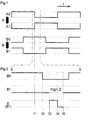
- Fig. 1 shows the typical energization scheme of a bipolar stepper motor 2-strand power supply in full step process
- Fig. 1 In the upper part of Fig. 1 is next to the schematic representation of a first Motor winding A with the winding connections A0 and A1 the sequence of the step energization pulses represented over time t. Below is the same in the form Current supply for the second motor winding B with the connections B0 and B1 specified.
- the second motor winding B is connected to the Current supply lines connected, so that the current supply according to FIG. 1 can continue.
- the time interval t1 - t5 is short against the duration of one Step pulse, so that no impairment of the torque behavior or Step execution occurs with the stepper motor.
- Figure 3 shows in the same representation as Figure 2 a section of the Current supply scheme according to FIG. 1.
- the response pulse is detected.
- the winding energization of the motor winding A is as usual continued.
- the inventive method is equally in full, half and Micro step method applicable.
- the circuit implementation of the method according to the invention is relative simple, since no A-D converters are required, just a simple pulse counter circuit, which enables the measurement of the duration of the response pulse t3-t4.
Landscapes
- Engineering & Computer Science (AREA)
- Power Engineering (AREA)
- Control Of Stepping Motors (AREA)
- Eye Examination Apparatus (AREA)
Abstract
Description
Die Erfindung betrifft ein Verfahren zur sensorlosen Schritterkennung bei Schrittmotoren durch Analyse der Motorbestromung.The invention relates to a method for sensorless step detection Stepper motors by analyzing the motor current.
Zur Positionsbestimmung von mit Schrittmotoren angetriebenen Systemen sind nach dem Stand der Technik verschiedene Möglichkeiten bekannt. Man kann beispielsweise die Position des angetriebenen Bauteils mittels Absolutwert-Positionssensoren unmittelbar erfassen. Diese Version ist zwar nicht auf Schrittmotoren beschränkt, scheidet jedoch in den meisten Fällen wegen des hohen Material- und Kostenaufwandes aus.For determining the position of systems driven by stepper motors are according to known various possibilities in the prior art. One can, for example the position of the driven component using absolute value position sensors capture immediately. While this version is not limited to stepper motors, differs in most cases because of the high material and Cost out.
Durch die Eigenschaft von Schrittmotoren, jeweils diskrete Schritte, d.h. Winkelinkremente, auszuführen, kann die Positionsbestimmung einfach dadurch erfolgen, daß von einem räumlich definierten Startpunkt mittels eines elektronischen Zählers die Anzahl der ausgeführten Schritte überwacht, d.h. gezählt wird. Für eine derartige Positionserkennung müssen im wesentlichen die folgenden Voraussetzungen realisiert werden: Zum einen muß der tatsächliche Startpunkt, in der Regel ein Endanschlag, als Ausgangspunkt der Bewegung erkannt werden und zum anderen muß laufend überwacht werden, ob bei jeder Schritt-Motorwicklungsbestromung tatsächlich ein Schritt ausgeführt worden ist.Due to the property of stepper motors, discrete steps, i.e. Angle increments can be carried out simply by determining the position take place from a spatially defined starting point by means of an electronic Counter monitors the number of steps performed, i.e. is counted. For one Such position detection essentially have the following requirements be realized: On the one hand, the actual starting point, usually a End stop, to be recognized as the starting point of the movement and to the other must be continuously monitored, whether with each step motor winding energization a step has actually been taken.
Diese beiden Voraussetzungen lassen sich mit externen Sensoren, beispielsweise Endschaltern und Kodierscheiben, kontrollieren, was allerdings aufwendig und kostenintensiv ist. Alternativ sind sensorlose Verfahren zur Schritterkennung bekannt, bei dem der Speisestrom oder die Speisespannung während der Bestromung der Motorwicklungen analysiert wird.These two requirements can be met with external sensors, for example Limit switches and coding disks, check, which is complicated and is expensive. Alternatively, sensorless methods for step detection are known in which the supply current or the supply voltage during energization of the Motor windings is analyzed.
Ein derartiges Verfahren und eine Vorrichtung zur Bewegungserkennung eines mehrphasigen Schrittmotors ist beispielsweise aus der DE 40 35 970 A1 bekannt. Darin werden die Spannungen zweier Phasen, d.h. die an den Motorwicklungen anliegenden Spannungen, mittels eines Mikrocomputers ausgewertet. Im einzelnen treten im Blockierfall Spannungseinbrüche bei den Phasenspannungen auf, die registriert werden. Das Verfahren soll zwar gegen Hochfrequenzstörungen unempfindlich sein, weist jedoch eine Reihe anderer Nachteile auf: Die Bewegungserkennung ist nämlich nur an mehrphasigen, unipolaren Schrittmotoren und nicht an bipolaren Schrittmotoren möglich. Außerdem sind die Spannungseinbrüche nur dann meßbar, wenn die Stromquelle relativ hochohmig ist; in der Regel müssen also Shunt-Widerstände eingesetzt werden. Dies bedingt natürlich einen erheblichen Bauteileaufwand und zudem eine ungünstige Energiebilanz aufgrund der am Widerstand umgesetzten Verlustwärme.Such a method and a device for motion detection of a Multi-phase stepper motor is known for example from DE 40 35 970 A1. In this the voltages of two phases, i.e. those on the motor windings Voltages, evaluated by means of a microcomputer. In detail occur in Blocking case voltage dips in the phase voltages that registered become. Although the method is said to be insensitive to radio frequency interference, however, has a number of other disadvantages: namely, motion detection is only on multi-phase, unipolar stepper motors and not on bipolar stepper motors possible. In addition, the voltage dips can only be measured if the Power source is relatively high impedance; usually shunt resistors be used. Of course, this requires a considerable amount of components and also an unfavorable energy balance due to the implementation of the resistor Waste heat.
In der EP 0 462 050 A1 ist ebenfalls ein Verfahren und eine Schaltung zum Erfassen des Außertrittfallens eines Schrittmotors beschrieben. Der jeweils durch die Motorwicklungen fließende Strom wird an einem Shunt-Widerstand abgegriffen und ausgewertet. Dabei hat man ebenfalls wie in der vorgenannten Druckschrift die Probleme durch die Verwendung des Shunt-Widerstands, Eine weitere Schwierigkeit ist, daß Strommessungen unter bestimmten Betriebsbedingungen, beispielsweise bei Spannungsschwankungen, wie sie häufig in Bordnetzen von Kraftfahrzeugen auftreten, relativ fehleranfällig sind, was nur durch aufwendige Entstör- und Stabilisierungsmaßnahmen ausgeglichen werden kann.EP 0 462 050 A1 also contains a method and a circuit for detecting described the stepping down of a stepping motor. The one by the Current flowing through motor windings is tapped at a shunt resistor and evaluated. You also have the same as in the aforementioned publication Problems from using the shunt resistor, another difficulty is that current measurements under certain operating conditions, for example at Voltage fluctuations, as they often occur in vehicle electrical systems, are relatively susceptible to errors, which is only possible through complex interference suppression and Stabilization measures can be compensated.
In der EP 0 402 220 A1 und der EP 0 574 339 A 2 sind ebenfalls Verfahren zur Schritterkennung bei Schrittmotoren erläutert, welche allerdings ebenfalls die vorgenannten Unzulänglichkeiten aufweisen.Methods are also described in EP 0 402 220 A1 and EP 0 574 339 A 2 Step detection for stepper motors explained, which, however, also the have the aforementioned shortcomings.
Daraus ergibt sich die Aufgabe der Erfindung, die vorgenannten Probleme zu vermeiden. Insbesondere soll das Verfahren möglichst störungsunempfindlich sein und sicheren Betrieb bei allen Betriebszuständen gewährleisten. Außerdem sollen unipolare und bipolare Schrittmotoren gleichermaßen einsetzbar sein. This results in the object of the invention, the aforementioned problems avoid. In particular, the method should be as insensitive to interference as possible and Ensure safe operation in all operating conditions. They are also said to be unipolar and bipolar stepper motors can be used equally.
Zur Lösung dieser Probleme schlägt die Erfindung ein Verfahren mit folgenden Verfahrensschritten vor:
- Einprägen eines definierten Stroms auf eine zweite Motorwicklung nach einer Stromrichtungsumkehr Motorwicklungs-Bestromung einer ersten Motorwicklung;
- Hochohmig-Schalten eines Motorwicklungsanschlusses der zweiten Motorwicklung;
- Erfassen des Antwortsignals an dem hochohmig geschalteten Motorwicklungsanschluß;
- Auswerten der Dauer des Antwortsignals.
- Impressing a defined current on a second motor winding after a reversal of current direction motor winding energizing a first motor winding;
- High-resistance switching of a motor winding connection of the second motor winding;
- Detecting the response signal at the high-resistance switched motor winding connection;
- Evaluate the duration of the response signal.
Bei der Durchführung des erfindungsgemäßen Verfahrens erfolgt eine modulierte Bestromung der einzelnen Motorwicklungen. Vorteile ergeben sich daraus, daß keine Strommessungen vorgenommen werden, wodurch keine Shunt-Widerstände und die zur Auswertung notwendigen Analogkomponenten benötigt werden, so daß die gesamte Schaltung im Gegensatz zu nach dem Stand der Technik bekannten Verfahren vorteilhafter auf einem integrierten Schaltkreis, beispielsweise auf einem ASIC (Application Specific Intergrated Circuit), integrierbar ist.When carrying out the method according to the invention, there is a modulated one Powering the individual motor windings. Advantages result from the fact that none Current measurements are made, eliminating any shunt resistors and the Analog components required for evaluation are required so that the entire circuit in contrast to known in the prior art Method more advantageously on an integrated circuit, for example on a ASIC (Application Specific Integrated Circuit), can be integrated.
Im Gegensatz zu nach dem Stand der Technik bekannten Verfahren, die zum Erkennen eines Schrittverlustes den Schwingungszustand, d.h. das sogenannte Toggeln, an einem festen oder elastischen Anschlag benötigen und somit eine Vollblockierung der Welle in einem fixen Zustand nicht erkennen können, ermöglicht das erfindungsgemäße Verfahren eine Erkennung auch solcher Betriebszustände. Dabei ist das erfindungsgemäße Verfahren im Falle des Toggelns am Anschlag wesentlich unempfindlicher gegen leitungsgebundene Störungen.In contrast to methods known from the prior art which are used for Detection of a step loss the vibration state, i.e. the so-called Toggle, need at a fixed or elastic stop and therefore one Full blockage of the shaft in a fixed state cannot be detected the method according to the invention also recognizes such operating states. The method according to the invention is in the case of toggle at the stop much less sensitive to conducted interference.
Im einzelnen wird zur Durchführung des erfindungsgemäßen Verfahrens nach einer Stromrichtungsumkehr der Motorwicklungs-Bestromung einer ersten Motorwicklung, d.h. nach der Beendigung eines Schrittimpulses, auf eine zweite Motorwicklung ein definierter Strom eingeprägt. Der Betrag des Stroms sollte in der Regel kleiner sein als der typische Betriebsstrom. Eine bevorzugte Ausführung des Verfahrens sieht dazu vor, daß die Wicklungsenden lediglich zeitlich definiert miteinander kurzgeschlossen werden. Dadurch wird der Spulenstrom durch den ohmschen Wilderstandsanteil auf einen bestimmten Wert reduziert.In detail, the method according to the invention is carried out according to a Reversal of current direction of the motor winding energization of a first motor winding, i.e. after the completion of a step pulse, on a second motor winding defined current impressed. The amount of electricity should usually be less than the typical operating current. A preferred embodiment of the method provides for this before that the winding ends are only short-circuited to one another in a defined time become. As a result, the coil current is resisted by the ohmic portion of the game reduced a certain value.
Im nächsten Schritt wird ein Wicklungsende der zweiten Motorwicklung hochohmig geschaltet, d.h. der Stromkreis wird geöffnet und das eine Wicklungsende an den potentialfreien Eingang einer Auswerteelektronik angeschlossen.In the next step, one winding end of the second motor winding becomes high-resistance switched, i.e. the circuit is opened and the one winding end to the potential-free input of evaluation electronics connected.
Durch ihre Induktivität wird in der hochohmig geschalteten, mit der Auswerteelektronik verbundenen Motorwicklung ein als Antwortsignal bezeichneter Impuls induziert. Die Länge dieses Impulses ist mit dem verwendeten Motortyp und der Betriebsart korreliert. Das erfindungsgemäße Verfahren macht sich diesen Umstand derart zunutze, daß Differenzen in der Dauer der Antwortimpulse bereits als eindeutiger Hinweis auf eine abweichende Rotorposition gewertet werden, d.h. als Schrittverlust.Due to its inductance, the evaluation electronics switch in the high-resistance circuit connected motor winding induces a pulse called a response signal. The The length of this pulse is correlated with the motor type used and the operating mode. The method according to the invention takes advantage of this fact in such a way that Differences in the duration of the response impulses are already a clear indication of one deviating rotor position, i.e. as a step loss.
Die Messung der Zeitdauer des Antwortimpulses erfordert nur einen relativ geringen schaltungstechnischen Aufwand. Dabei ist die Messung im Gegensatz zu absoluten Strommessungen weitgehend unempfindlich gegen Spannungsschwankungen im System und sonstige Störungen.Measuring the duration of the response pulse requires only a relatively small amount circuit complexity. The measurement is in contrast to absolute Current measurements largely insensitive to voltage fluctuations in the System and other disorders.
Nach der Auswertung der Dauer des Antwortsignals wird die zweite Motorwicklung wieder an die Versorgungsleitungen geschaltet, so daß Motorwicklungs-Bestromung je nach Ergebnis der vorangegangenen Auswertung fortgesetzt werden kann. Dabei wird zweckmäßigerweise der Bestromungszyklus unterbrochen, wenn eine Blockierung detektiert wird. Damit kann in elektromechanischen Systemen ein Endschalter eingespart werden; zugleich wird die Lärmbelästigung durch Oszillieren am mechanischen Anschlag sowie mechanische Überlast vermieden.After evaluating the duration of the response signal, the second motor winding switched back to the supply lines, so that motor winding energization depending after the result of the previous evaluation can be continued. Doing so expediently interrupted the energization cycle when a blockage is detected. This means that a limit switch can be used in electromechanical systems be saved; at the same time, the noise pollution caused by oscillation on mechanical stop and mechanical overload avoided.
Vorzugsweise wird bei dem erfindungsgemäßen Verfahren die Motorwicklung gegen Masse (GND) kurzgeschlossen und anschließend nach einem vorgegebenen Zeitintervall die Dauer des High-lmpulses gemessen. Durch den Kurzschluß gegen Masse erfolgt eine störungsfreie Festsetzung des Motorwicklungs-Stroms. In dieser Beschaltung weist das Antwortsignal einen High-Impuls auf, dessen Dauer Aufschluß über den Betriebszustand erlaubt. In the method according to the invention, the motor winding is preferably opposed Ground (GND) short-circuited and then according to a specified one Time interval the duration of the high pulse measured. By short circuit against Ground takes place a trouble-free fixing of the motor winding current. In this Circuitry, the response signal has a high pulse, the duration of which is information allowed over the operating state.
Ein Vorzug des erfindungsgemäßen Verfahrens liegt in seiner besonderen Flexibilität, so daß eine Anwendung gleichermaßen vorteilhaft ist bei 1- oder 2-Strang-Bestromung sowie an bipolaren wie auch an unipolaren Schrittmotoren.An advantage of the method according to the invention lies in its particular flexibility, so that an application is equally advantageous with 1 or 2-strand energization as well as on bipolar and unipolar stepper motors.
Dadurch, daß gegenüber herkömmlichen Analyseverfahren weder Shunt-Widerstände noch andere Analogkomponenten erforderlich sind, bietet sich erstmals die besonders vorteilhafte Möglichkeit, alle Bauelemente der Schaltungsanordnung zur Durchführung des erfindungsgemäßen Verfahrens in einem ASIC zu integrieren. Insbesondere bei der Großserienfertigung ergibt sich ein ausgesprochen günstiger Arbeits-, Material- und Kostenaufwand.The fact that compared to conventional analysis methods, neither shunt resistors for the first time, other analog components are required advantageous way to carry out all components of the circuit arrangement to integrate the method according to the invention in an ASIC. Especially at the large-scale production results in an extremely favorable work, material and Cost.
Die erfindungsgemäße Modulation im Bestromungszyklus hat im Vergleich zu den Schrittimpulsen eine so kurze Zeitdauer, daß sich praktisch kein meßbarer Einfluß auf die Drehmomentcharakteristik oder die Laufeigenschaften ergibt.The modulation according to the invention in the energization cycle has compared to that Step impulses are so short that there is practically no measurable influence the torque characteristic or the running properties.
Eine besonders vorteilhafte Alternative des erfindungsgemäßen Verfahrens ist durch folgende Verfahrensschritte gekennzeichnet:
- Einprägen eines definierten Stroms auf eine Motorwicklung auf ein externes Triggersignal;
- Hochohmig-Schalten eines Motorwicklungsanschlusses der Motorwicklung;
- Erfassen des Antwortsignals an den hochohmig geschalteten Motorwicklungsanschluß;
- Auswerten der Dauer des Antwortsignals.
- Impressing a defined current on a motor winding onto an external trigger signal;
- High-resistance switching of a motor winding connection of the motor winding;
- Detecting the response signal at the high-resistance motor winding connection;
- Evaluate the duration of the response signal.
In dieser Verfahrensaiternative wird der definierte Strom nicht durch die Stromrichtungsumkehr einer Motorwicklung getriggert, sondern duch ein beliebiges externes Triggersignal. Beispielsweise kann dieses Triggersignal von einem Signalgeber stammen, der periodische Impulse abgibt, die je nach den jeweiligen Anforderungen eine höhere oder auch eine niedrigere Frequenz aufweisen können als beispielsweise die typischen Bestromungsimpulse. Der besondere Vorteil ergibt sich daraus, daß das Triggersignal, welches die übrigen Verfahrensschritte einleitet, unabhängig von einer Stromrichtungsumkehr der Motorwicklungs-Bestromung ist und somit auch unabhängig davon, ob der Motor aktiv bestromt wird, d. h. durch die Bestromung ein Antriebsdrehmoment oder ein Haltemoment erzeugt wird. Damit ergibt sich erstmals die Möglichkeit, mittels eines gewöhnlichen Schrittmotors gleich welcher Bauart, auch nichtaktive Motorbewegungen zu erfassen. Dieser Fail liegt regelmäßig dann vor, wenn auf den Motor eine externe Bewegung eingeprägt wird, die von dem vorgesehenen Bestromungsschema abweicht. Hierbei können mehrere Fälle unterschieden werden: Dies ist einmal die Bewegung eines nicht aktiv bestromten Motors von außen. Zweitens erfaßt dies die aufgezwungene Bewegung eines Motors mit Haltebestromung und drittens handelt es sich um von außen aufgezwungene Bewegungen, deren Geschwindigkeit oder Drehsinn von der jeweils vorgegebenen Motorbestromung abweicht.In this process alternative, the defined current is not through the Current direction reversal of a motor winding triggered, but by any external trigger signal. For example, this trigger signal from a Signal generator originate, which emits periodic impulses depending on the respective Requirements can have a higher or a lower frequency than for example the typical current impulses. The particular advantage arises from the fact that the trigger signal, which initiates the remaining process steps, is independent of a reversal of the current direction of the motor winding energization and thus regardless of whether the motor is actively powered, d. H. through the Energizing a drive torque or a holding torque is generated. So that results the possibility for the first time, using an ordinary stepper motor of any kind Design to also detect inactive motor movements. This fail is regular then, if an external movement is impressed on the motor by the provided the current supply scheme deviates. There can be several cases to be distinguished: This is the movement of someone who is not actively energized Motors from the outside. Second, this senses the forced movement of an engine with holding current and third, it is imposed from the outside Movements, their speed or direction of rotation from the given one Motor current deviates.
Die externe Triggerung ermöglicht die Messung der aktuellen Rotorposition mittels des erfindungsgemäßen lmpulsdauer-Meßverfahrens. Dies bedeutet nichts anderes, als daß der Schrittmotor als Drehwinkelgeber betrieben wird. Dabei wird nicht nur die Erfassung der Drehbewegung ermöglicht, sondern anhand der Phasenlage an den einzelnen Spulen auch die Drehrichtung.External triggering enables the current rotor position to be measured using the pulse duration measuring method according to the invention. This means nothing else than that the stepper motor is operated as a rotary encoder. Not only that Allows detection of the rotary movement, but based on the phase position of the individual coils also the direction of rotation.
Eine weitere, besonders vorteilhafte Alternative des erfindungsgemäßen Verfahrens sieht folgende Verfahrensschritte vor:
- Hochohmig-Schalten eines Motorwicklungsanschlusses, nachdem in der Bestromung einer Motorwicklung eine High-Low-Flanke aufgetreten ist;
- Erfassen des Antwortsignals an dem hochohmig geschalteten Motorwicklungsanschluß;
- Auswerten der Dauer des Anwortsignals.
- High-resistance switching of a motor winding connection after a high-low edge has occurred in the current supply to a motor winding;
- Detecting the response signal at the high-resistance switched motor winding connection;
- Evaluate the duration of the response signal.
Im wesentlichen erfolgt die Schritterkennung bei dieser Verfahrensvariante wie zuvor bereits für die Triggerung durch ein externes Triggersignal beschrieben. Im Unterschied dazu erfolgt die Triggerung nunmehr durch eine High-Low-Flanke des Stroms in einer Motorwicklung, wie sie beispielsweise bei einer Stromrichtungsumkehr im Verlauf des Motorbestromungs-Taktzyklus zwangsläufig auftritt. Danach wird zeitverzögert ein beliebiger Motorwicklungsanschluß in der bereits zuvor beschriebenen Weise hochohmig geschaltet, um anschließend den Antwortimpuls zu erfassen und auszuwerten, wie ebenfalls bereits beschrieben.In this method variant, the step detection essentially takes place as before already described for triggering by an external trigger signal. The difference for this purpose the triggering is now carried out by a high-low edge of the current in one Motor winding, as for example in the case of a reversal of the current direction in the course of Motor energization clock cycle inevitably occurs. Then a time delay is set any motor winding connection in the manner already described switched high impedance to then capture the response pulse and evaluate, as also already described.
Wie bei der vorbeschriebenen externen Triggerung hat diese Ausbildung des Verfahrens den Vorteil, das für eine Schritterkennung lediglich eine einzige Motorwicklung genutzt wird. Dabei ist jedoch kein externes Triggersignal erforderlich, es wird vielmehr wie in der an erster Stelle beschriebenen Ausgestaltung des erfindungsgemäßen Verfahrens auf die bei der Motorwicklungsbestromung vorhandenen High-Low-Flanken, die durch die Stromrichtungsumkehr jeweils hervorgerufen werden, zurückgegriffen. Dadurch, daß die bevorzugte Möglichkeit gegeben ist, nach dem Auftreten einer High-Low-Flanke in einer Motorwicklung an derselben Motorwicklung den Antwortimpuls zu erfassen, wobei alle anderen Motorwicklungen vollkommen ungestört bestromt bleiben, ergeben sich als besondere Vorteile, daß die Störabstrahlung geringer ist und außerdem ein geringerer Drehmomentverlust auftritt, als wenn die Erfassung des Antwortsignals an einer zweiten Motorwicklung erfolgt.As with the external trigger described above, this training of Process the advantage that only one step detection Motor winding is used. However, no external trigger signal is required, it is rather as in the configuration of the method according to the invention in the motor winding energization existing high-low edges, each by the reversal of the current direction are caused. By being the preferred option is given after the occurrence of a high-low edge in a motor winding the same motor winding to detect the response pulse, all others Motor windings remain completely undisturbed, are special Advantages that the interference radiation is less and also less Torque loss occurs as if the detection of the response signal on a second motor winding takes place.
Im folgenden wird das erfindungsgemäße Verfahren anhand der Zeichnungen näher erläutert.The method according to the invention is described in more detail below with reference to the drawings explained.
Es zeigen im einzelnen:
- Fig. 1
- ein typisches Bestromungsschema der Motorwicklungen;
- Fig. 2
- den gestrichelt eingezeichneten Zeitausschnitt aus Fig. 1 in vergrößerter Darstellung;
- Fig. 3
- den gestrichelt eingezeichneten Zeitausschnitt aus Fig. 1 in vergrößerter Darstellung bei einer zweiten Ausführungsform des erfindungsgemäßen Verfahrens.
- Fig. 1
- a typical energization scheme of the motor windings;
- Fig. 2
- the dashed time section from Figure 1 in an enlarged view.
- Fig. 3
- the dashed time section from FIG. 1 in an enlarged view in a second embodiment of the method according to the invention.
Fig. 1 zeigt das typische Bestromungsschema eines bipolaren Schrittmotors mit 2-Strang-Bestromung im VollschrittverfahrenFig. 1 shows the typical energization scheme of a bipolar stepper motor 2-strand power supply in full step process
Im oberen Teil von Fig. 1 ist neben der schematischen Darstellung einer ersten Motorwicklung A mit den Wicklungsanschlüssen A0 und A1 die Abfolge der Schritt-Bestromungsimpulse über der Zeit t dargestellt. Darunter ist in derselben Form die Bestromung für die zweite Motorwicklung B mit den Anschlüssen B0 und B1 angegeben.In the upper part of Fig. 1 is next to the schematic representation of a first Motor winding A with the winding connections A0 and A1 the sequence of the step energization pulses represented over time t. Below is the same in the form Current supply for the second motor winding B with the connections B0 and B1 specified.
Fig. 2 zeigt in zeitlich gedehnter Darstellung zum einen das Bestromungsschema an den Anschlüssen B0 und B1 der zweiten Motorwicklung B im Bereich der Stromrichtungsumkehr an der ersten Motorwicklung A und zusätzlich den Signalverlauf S, der während der Hochohmig-Schaltung an B1 gemessen wird,2 shows, on the one hand, the current flow diagram in a time-expanded representation the connections B0 and B1 of the second motor winding B in the area of Reversal of current direction on the first motor winding A and additionally the signal curve S, which is measured at B1 during the high-resistance circuit,
Die Stromrichtungsumkehr der Motorwicklungs-Bestromung der Motorwicklung A erfolgt zum Zeitpunkt t1. Nach einer voreingestellten Verzögerung, zum Zeitpunkt t2 werden die Wicklungsenden B0 und B1 der zweiten Motorwicklung B gegen Masse (GND) kurzgeschlossen. Nach einer weiteren, voreingestellten Verzögerung wird der Anschluß B1 zum Zeitpunkt t3 hochohmig geschaltet, d.h. an dem potentialfreien Eingang einer hochohmigen Meßschaltung. Nunmehr wird an B1 das Signal S erfaßt, welches im dargestellten Beispiel ein High-lmpuls ist. Dieser beginnt zur Zeit t3 und endet zum Zeitpunkt t4. Die Zeitdauer dieses Anwortsignals ist durch den verwendeten Schrittmotor und die Betriebsbedingungen eindeutig definiert.The reversal of the current direction of the motor winding energization of the motor winding A takes place at time t1. After a preset delay, at time t2 the winding ends B0 and B1 of the second motor winding B become ground (GND) shorted. After a further, preset delay, the Connection B1 switched to high resistance at time t3, i.e. on the potential-free Input of a high-resistance measuring circuit. The signal S is now detected at B1, which is a high pulse in the example shown. This begins at time t3 and ends at time t4. The duration of this response signal is by the one used Stepper motor and the operating conditions clearly defined.
Zum späteren Zeitpunkt t5 wird die zweite Motorwicklung B wieder an die Bestromungsleitungen angeschlossen, so daß die Bestromung gemäß Fig. 1 fortgesetzt werden kann. Dabei ist das Zeitintervall t1 - t5 kurz gegen die Dauer eines Schrittimpulses, so daß keine Beeinträchtigung des Drehmomentverhaltens oder der Schrittausführung bei dem Schrittmotor auftritt.At a later time t5, the second motor winding B is connected to the Current supply lines connected, so that the current supply according to FIG. 1 can continue. The time interval t1 - t5 is short against the duration of one Step pulse, so that no impairment of the torque behavior or Step execution occurs with the stepper motor.
Sobald eine Abweichung bei der erfaßten Zeitdauer des Antwortsignals t3 - t4 auftritt, ist dies ein Zeichen dafür, daß bei der vorangegangenen Stromrichtungsumkehr in der ersten Motorwicklung kein vollständiger Schritt ausgeführt wurde, d.h. eine Blockierung vorliegt. Dies kann beispielsweise dann der Fall sein, wenn der Schrittmotor gegen einen Anschlag gefahren ist. As soon as a deviation occurs in the detected time duration of the response signal t3-t4, this is a sign that the previous reversal of the current direction in the no complete step has been carried out after the first motor winding, i.e. a blockage is present. This can be the case, for example, if the stepper motor counteracts drove an attack.
Figur 3 zeigt in derselben Darstellung wie Figur 2 einen Ausschnitt aus dem Bestromungsschema gemäß Figur 1. Im Unterschied zu dem Verfahren gemäß Figur 2 wird nach dem Auftreten einer High-Low-Flanke zum Zeitpunkt t1 am Wicktungsanschluß A0 zum Zeitpunkt t3 der Wicklungsanschluß A1 derselben Motorwicklung A hochohmig geschaltet. Dann wird wiederum zwischen den Zeitpunkten t3 und t4, wie bereits zuvor erläutert, der Antwortimpuls erfaßt. Zu einem späteren Zeitpunkt t5 wird die Wicklungsbestromung der Motorwicklung A wie gewohnt fortgesetzt.Figure 3 shows in the same representation as Figure 2 a section of the Current supply scheme according to FIG. 1. In contrast to the method according to FIG. 2 is after the occurrence of a high-low edge at time t1 Winding connection A0 at the time t3 of the winding connection A1 of the same Motor winding A switched high impedance. Then again between the At times t3 and t4, as already explained above, the response pulse is detected. To a at a later point in time t5, the winding energization of the motor winding A is as usual continued.
In der zuletzt beschriebenen erfindungsgemäßen Verfahrensweise wird die andere Motorwicklung B vollkommen ungestört bestromt. Dadurch wird während der Erfassung des Antwortimpulses das Drehmoment praktisch nicht verringert; außerdem ist die Störabstrahlung geringer.In the procedure according to the invention described last, the other Motor winding B energized completely undisturbed. This will during the capture the response pulse practically does not reduce the torque; besides, that is Noise emission lower.
Das erfindungsgemäße Verfahren ist gleichermaßen im Voll-, Halb- und Mikroschrittverfahren anwendbar.The inventive method is equally in full, half and Micro step method applicable.
Die schaltungstechnische Realisierung des erfindungsgemäßen Verfahrens ist relativ simpel, da keine A-D-Wandler benötigt werden, sondern nur eine einfache impuls-Zählschaltung, die die Messung der Zeitdauer des Antwortimpulses t3-t4 ermöglicht.The circuit implementation of the method according to the invention is relative simple, since no A-D converters are required, just a simple pulse counter circuit, which enables the measurement of the duration of the response pulse t3-t4.
Claims (12)
- A method for sensor-free step recognition in step motors by analysing the supply of current to the motor, characterised by the method steps:impressing a defined current upon a second motor winding following a reversal in the current direction of the motor winding current supply of a first motor winding;high-impedance connecting of a motor winding connection of the second motor winding;detecting the response signal at the motor winding connection connected at high-impedance;evaluating the duration of the response signal.
- A method according to Claim 1, characterised in that the current is impressed by time-defined short-circuiting of the motor winding.
- A method according to Claim 1, characterised in that the motor winding is short-circuited in response to mass (GND) and the length of the high-impulse is then measured after a predetermined time interval.
- A method for sensor-free step recognition in step motors by analysing the supply of current to the motor, characterised by the method steps:impressing a defined current upon a motor winding following an external trigger signal;high-impedance connecting of a motor winding connection;detecting the response signal at the motor winding connection connected at high-impedance;evaluating the duration of the response signal.
- A method according to Claim 4, characterised in that the external trigger signal is periodic.
- A method for sensor-free step recognition in step motors by analysing the supply of current to the motor, characterised by the method steps:high-impedance connection of a motor winding connection after a high-low-flank has occurred in the supply of current to a motor winding;detecting the response signal at the motor winding connection connected at high-impedance;evaluating the duration of the response signal.
- A method according to Claim 6, characterised in that the response signal is perceived with a time delay at a motor winding connection to the motor winding, in whose supply of current there has previously been a high-low-flank.
- A method according to one of Claims 1, 4 or 6, characterised in that the method is carried out in the presence of 1-line-current supply.
- A method according to one of Claims 1, 4 or 6, characterised in that the method is carried out in the presence of 2-line-current supply.
- A method according to one of Claims 1, 4 or 6, characterised in that the method is carried out on a bipolar step motor.
- A method according to one of Claims 1, 4 or 6, characterised in that the method is carried out on a unipolar step motor.
- A circuit arrangement for implementation of the method according to one of Claims 1, 4 or 6, characterised in that all components are integrated in an ASIC.
Applications Claiming Priority (5)
| Application Number | Priority Date | Filing Date | Title |
|---|---|---|---|
| DE19630591 | 1996-07-30 | ||
| DE19630591 | 1996-07-30 | ||
| DE19653460 | 1996-12-20 | ||
| DE19653460A DE19653460C2 (en) | 1996-07-30 | 1996-12-20 | Process for sensorless step detection in stepper motors |
| PCT/EP1997/003923 WO1998005116A1 (en) | 1996-07-30 | 1997-07-21 | Sensorless step recognition process for stepping motors |
Publications (2)
| Publication Number | Publication Date |
|---|---|
| EP0916180A1 EP0916180A1 (en) | 1999-05-19 |
| EP0916180B1 true EP0916180B1 (en) | 2003-10-08 |
Family
ID=26027926
Family Applications (1)
| Application Number | Title | Priority Date | Filing Date |
|---|---|---|---|
| EP97933690A Expired - Lifetime EP0916180B1 (en) | 1996-07-30 | 1997-07-21 | Sensorless step recognition process for stepping motors |
Country Status (8)
| Country | Link |
|---|---|
| US (1) | US6285156B1 (en) |
| EP (1) | EP0916180B1 (en) |
| JP (1) | JP2000516079A (en) |
| AT (1) | ATE251815T1 (en) |
| BR (1) | BR9711817B1 (en) |
| DE (2) | DE19653460C2 (en) |
| DK (1) | DK0916180T3 (en) |
| WO (1) | WO1998005116A1 (en) |
Families Citing this family (3)
| Publication number | Priority date | Publication date | Assignee | Title |
|---|---|---|---|---|
| US7338260B2 (en) * | 2004-03-17 | 2008-03-04 | Baxier International Inc. | System and method for controlling current provided to a stepping motor |
| KR101114739B1 (en) * | 2006-03-17 | 2012-03-29 | 니혼 서보 가부시키가이샤 | Stepping motor control apparatus |
| JP2012527209A (en) * | 2009-05-13 | 2012-11-01 | エルモス セミコンダクター エーゲー | Method for detecting faults in an electrically commutated electric motor |
Family Cites Families (18)
| Publication number | Priority date | Publication date | Assignee | Title |
|---|---|---|---|---|
| US4282471A (en) * | 1979-05-14 | 1981-08-04 | Qwint Systems Inc. | Control system for a multi-phase motor |
| US4319174A (en) * | 1980-03-31 | 1982-03-09 | International Business Machines Corporation | Stepper motor drive system |
| JPS56158978A (en) * | 1980-05-13 | 1981-12-08 | Citizen Watch Co Ltd | Electronic watch |
| EP0046722A3 (en) * | 1980-08-25 | 1982-11-17 | United Technologies Corporation | Stepper motor motion sensor |
| US4717866A (en) * | 1986-04-23 | 1988-01-05 | Archive Corporation | Stepping motor excitation sequences |
| JPH0640423B2 (en) * | 1986-10-13 | 1994-05-25 | 富士通株式会社 | Positioning control method for information storage device |
| JPS63140694A (en) * | 1986-12-01 | 1988-06-13 | Janome Sewing Mach Co Ltd | Stepping motor driving device |
| US4843292A (en) * | 1987-03-02 | 1989-06-27 | Yokogawa Electric Corporation | Direct drive motor system |
| US4772839A (en) * | 1987-10-27 | 1988-09-20 | General Electric Company | Rotor position estimator for switched reluctance motor |
| US4855660A (en) * | 1988-02-18 | 1989-08-08 | Siemens-Bendix Automotive Electronics L.P. | Microstepping of an unipolar stepping motor |
| US4929879A (en) * | 1988-02-18 | 1990-05-29 | Siemens-Bendix Automotive Electronics L.P. | Microstepping of an unipolar stepping motor |
| US4851755A (en) | 1988-03-01 | 1989-07-25 | Ampex Corporation | Low power stepper motor drive system and method |
| US4999556A (en) * | 1988-03-31 | 1991-03-12 | Scott Motors, Inc. | Pulse width modulator motor control |
| DE69017269T2 (en) * | 1989-06-07 | 1995-06-22 | Valeo Thermique Habitacle | Method and device for controlling a stepper motor. |
| DE4035970A1 (en) * | 1989-11-29 | 1991-06-06 | Uher Ag | Recognition of movement of polyphase unipolar stepping motor - is based on multiple samples of voltage taken from successive phases for comparison with desired value |
| CH680547A5 (en) * | 1990-06-12 | 1992-09-15 | Saia Ag | |
| FR2692417B1 (en) * | 1992-06-12 | 1995-07-28 | Sextant Avionique | SYNCHRONOUS MOTOR CONTROL SYSTEM WITH MAGNET ROTOR. |
| ES2131899T3 (en) * | 1995-09-13 | 1999-08-01 | Valeo Electronique | CONTROL DEVICE OF A SINGLE-POLE STEP-BY-STEP MOTOR THAT ALLOWS THE DETECTION OF THE ROTOR LOCK. |
-
1996
- 1996-12-20 DE DE19653460A patent/DE19653460C2/en not_active Expired - Fee Related
-
1997
- 1997-07-21 BR BRPI9711817-6A patent/BR9711817B1/en not_active IP Right Cessation
- 1997-07-21 JP JP10508462A patent/JP2000516079A/en active Pending
- 1997-07-21 AT AT97933690T patent/ATE251815T1/en not_active IP Right Cessation
- 1997-07-21 DK DK97933690T patent/DK0916180T3/en active
- 1997-07-21 DE DE59710836T patent/DE59710836D1/en not_active Expired - Lifetime
- 1997-07-21 WO PCT/EP1997/003923 patent/WO1998005116A1/en active IP Right Grant
- 1997-07-21 US US09/230,693 patent/US6285156B1/en not_active Expired - Lifetime
- 1997-07-21 EP EP97933690A patent/EP0916180B1/en not_active Expired - Lifetime
Also Published As
| Publication number | Publication date |
|---|---|
| ATE251815T1 (en) | 2003-10-15 |
| DE19653460C2 (en) | 1999-10-28 |
| BR9711817A (en) | 2000-04-25 |
| BR9711817B1 (en) | 2009-08-11 |
| EP0916180A1 (en) | 1999-05-19 |
| DE19653460A1 (en) | 1998-02-05 |
| WO1998005116A1 (en) | 1998-02-05 |
| JP2000516079A (en) | 2000-11-28 |
| DE59710836D1 (en) | 2003-11-13 |
| DK0916180T3 (en) | 2004-01-19 |
| US6285156B1 (en) | 2001-09-04 |
Similar Documents
| Publication | Publication Date | Title |
|---|---|---|
| DE69603643T2 (en) | Position transmitter | |
| DE3706659C2 (en) | ||
| EP2105713B1 (en) | Positioning device and method for its operation | |
| DE2837187C2 (en) | ||
| DE4131128C1 (en) | ||
| DE102005047366A1 (en) | Rotary drive`s e.g. window lift drive, reversal of rotation direction determining device for motor vehicle, has sensor wheel with coded structure that is formed by coded sector of width and reference coded sector pair with another width | |
| DE69908691T2 (en) | Method for detecting the jamming of an object of a window drive device | |
| EP0916180B1 (en) | Sensorless step recognition process for stepping motors | |
| DE2545325B2 (en) | Circuit arrangement for measuring the insulation resistance of floating power circuits | |
| EP0890217B1 (en) | System for detecting abutment and blocking in a stepped motor | |
| DE19538163C1 (en) | Rotation rate and rotation direction detection method e.g. for water meter | |
| EP0898368B1 (en) | Sensor device | |
| DE69012069T2 (en) | TEST DEVICE OF THE STEERING WHEEL OF A VEHICLE. | |
| DE3321530C2 (en) | ||
| DE3608632C2 (en) | ||
| DE19632457C1 (en) | Switching circuit for function monitoring for vehicle wheel RPM measuring sensor | |
| DE10207338A1 (en) | Method and device for detecting the motor position of an electric motor | |
| DE19948892C2 (en) | Pulse detector and method for the detection of sinusoidal pulses | |
| EP1391735B1 (en) | Evaluation circuit for oscillator circuit sensors | |
| DE2144537C3 (en) | Signaling system | |
| DE102004055156A1 (en) | Device to detect the rotational position for starting commutation and excess current recognition for a brushless electric motor has phase comparator control logic and memory | |
| EP0351638A1 (en) | Method for safeguarding against loss of phase of constant-range phase-displaced phase voltages of a multi-phase tachogenerator, and circuit arrangement for performing said method | |
| WO2000039530A1 (en) | Sensor device for detecting a physical measured quantity | |
| DE69602144T2 (en) | Control device for a unipolar stepper motor to detect rotor blocking | |
| DE2828198C2 (en) | Circuit arrangement for the correct polarity control of the stepper motor of an electronically controlled analog clock after the frequency divider circuit that drives the stepper motor has been reset |
Legal Events
| Date | Code | Title | Description |
|---|---|---|---|
| PUAI | Public reference made under article 153(3) epc to a published international application that has entered the european phase |
Free format text: ORIGINAL CODE: 0009012 |
|
| 17P | Request for examination filed |
Effective date: 19990129 |
|
| AK | Designated contracting states |
Kind code of ref document: A1 Designated state(s): AT BE CH DE DK ES FI FR GB GR IE IT LI LU MC NL PT SE |
|
| RAP1 | Party data changed (applicant data changed or rights of an application transferred) |
Owner name: ELMOS SEMICONDUCTOR AG |
|
| GRAH | Despatch of communication of intention to grant a patent |
Free format text: ORIGINAL CODE: EPIDOS IGRA |
|
| GRAS | Grant fee paid |
Free format text: ORIGINAL CODE: EPIDOSNIGR3 |
|
| GRAA | (expected) grant |
Free format text: ORIGINAL CODE: 0009210 |
|
| AK | Designated contracting states |
Kind code of ref document: B1 Designated state(s): AT BE CH DE DK ES FI FR GB GR IE IT LI LU MC NL PT SE |
|
| PG25 | Lapsed in a contracting state [announced via postgrant information from national office to epo] |
Ref country code: NL Free format text: LAPSE BECAUSE OF FAILURE TO SUBMIT A TRANSLATION OF THE DESCRIPTION OR TO PAY THE FEE WITHIN THE PRESCRIBED TIME-LIMIT Effective date: 20031008 Ref country code: FR Free format text: LAPSE BECAUSE OF FAILURE TO SUBMIT A TRANSLATION OF THE DESCRIPTION OR TO PAY THE FEE WITHIN THE PRESCRIBED TIME-LIMIT Effective date: 20031008 |
|
| REG | Reference to a national code |
Ref country code: GB Ref legal event code: FG4D Free format text: NOT ENGLISH |
|
| REG | Reference to a national code |
Ref country code: CH Ref legal event code: EP |
|
| REG | Reference to a national code |
Ref country code: IE Ref legal event code: FG4D Free format text: GERMAN |
|
| REF | Corresponds to: |
Ref document number: 59710836 Country of ref document: DE Date of ref document: 20031113 Kind code of ref document: P |
|
| PG25 | Lapsed in a contracting state [announced via postgrant information from national office to epo] |
Ref country code: SE Free format text: LAPSE BECAUSE OF FAILURE TO SUBMIT A TRANSLATION OF THE DESCRIPTION OR TO PAY THE FEE WITHIN THE PRESCRIBED TIME-LIMIT Effective date: 20040108 Ref country code: GR Free format text: LAPSE BECAUSE OF FAILURE TO SUBMIT A TRANSLATION OF THE DESCRIPTION OR TO PAY THE FEE WITHIN THE PRESCRIBED TIME-LIMIT Effective date: 20040108 |
|
| PG25 | Lapsed in a contracting state [announced via postgrant information from national office to epo] |
Ref country code: ES Free format text: LAPSE BECAUSE OF FAILURE TO SUBMIT A TRANSLATION OF THE DESCRIPTION OR TO PAY THE FEE WITHIN THE PRESCRIBED TIME-LIMIT Effective date: 20040119 |
|
| REG | Reference to a national code |
Ref country code: DK Ref legal event code: T3 |
|
| GBT | Gb: translation of ep patent filed (gb section 77(6)(a)/1977) |
Effective date: 20040115 |
|
| REG | Reference to a national code |
Ref country code: CH Ref legal event code: NV Representative=s name: LUCHS & PARTNER PATENTANWAELTE |
|
| NLV1 | Nl: lapsed or annulled due to failure to fulfill the requirements of art. 29p and 29m of the patents act | ||
| PG25 | Lapsed in a contracting state [announced via postgrant information from national office to epo] |
Ref country code: LU Free format text: LAPSE BECAUSE OF NON-PAYMENT OF DUE FEES Effective date: 20040721 Ref country code: FI Free format text: LAPSE BECAUSE OF NON-PAYMENT OF DUE FEES Effective date: 20040721 Ref country code: AT Free format text: LAPSE BECAUSE OF NON-PAYMENT OF DUE FEES Effective date: 20040721 |
|
| PGFP | Annual fee paid to national office [announced via postgrant information from national office to epo] |
Ref country code: FR Payment date: 20040729 Year of fee payment: 8 |
|
| PG25 | Lapsed in a contracting state [announced via postgrant information from national office to epo] |
Ref country code: MC Free format text: LAPSE BECAUSE OF NON-PAYMENT OF DUE FEES Effective date: 20040731 |
|
| PG25 | Lapsed in a contracting state [announced via postgrant information from national office to epo] |
Ref country code: DK Free format text: LAPSE BECAUSE OF NON-PAYMENT OF DUE FEES Effective date: 20040802 |
|
| PLBE | No opposition filed within time limit |
Free format text: ORIGINAL CODE: 0009261 |
|
| STAA | Information on the status of an ep patent application or granted ep patent |
Free format text: STATUS: NO OPPOSITION FILED WITHIN TIME LIMIT |
|
| 26N | No opposition filed |
Effective date: 20040709 |
|
| EN | Fr: translation not filed | ||
| REG | Reference to a national code |
Ref country code: DK Ref legal event code: EBP |
|
| PG25 | Lapsed in a contracting state [announced via postgrant information from national office to epo] |
Ref country code: PT Free format text: LAPSE BECAUSE OF NON-PAYMENT OF DUE FEES Effective date: 20040308 |
|
| PGFP | Annual fee paid to national office [announced via postgrant information from national office to epo] |
Ref country code: IE Payment date: 20081209 Year of fee payment: 12 |
|
| REG | Reference to a national code |
Ref country code: CH Ref legal event code: PL Ref country code: CH Ref legal event code: AEN Free format text: DAS PATENT IST AUFGRUND DES WEITERBEHANDLUNGSANTRAGS VOM 03.02.2009 REAKTIVIERT WORDEN. |
|
| PGFP | Annual fee paid to national office [announced via postgrant information from national office to epo] |
Ref country code: BE Payment date: 20081211 Year of fee payment: 12 |
|
| BERE | Be: lapsed |
Owner name: *ELMOS SEMICONDUCTOR A.G. Effective date: 20090731 |
|
| REG | Reference to a national code |
Ref country code: CH Ref legal event code: PL Ref country code: CH Ref legal event code: AEN Free format text: DAS PATENT IST AUFGRUND DES WEITERBEHANDLUNGSANTRAGS VOM 25.02.2010 REAKTIVIERT WORDEN. |
|
| REG | Reference to a national code |
Ref country code: IE Ref legal event code: MM4A |
|
| PG25 | Lapsed in a contracting state [announced via postgrant information from national office to epo] |
Ref country code: BE Free format text: LAPSE BECAUSE OF NON-PAYMENT OF DUE FEES Effective date: 20090731 |
|
| PG25 | Lapsed in a contracting state [announced via postgrant information from national office to epo] |
Ref country code: IE Free format text: LAPSE BECAUSE OF NON-PAYMENT OF DUE FEES Effective date: 20090721 |
|
| REG | Reference to a national code |
Ref country code: DE Ref legal event code: R082 Ref document number: 59710836 Country of ref document: DE Representative=s name: SCHNEIDERS & BEHRENDT RECHTS- UND PATENTANWAEL, DE |
|
| REG | Reference to a national code |
Ref country code: DE Ref legal event code: R082 Ref document number: 59710836 Country of ref document: DE Representative=s name: SCHNEIDERS & BEHRENDT RECHTS- UND PATENTANWAEL, DE Effective date: 20150108 Ref country code: DE Ref legal event code: R081 Ref document number: 59710836 Country of ref document: DE Owner name: ELMOS SEMICONDUCTOR AKTIENGESELLSCHAFT, DE Free format text: FORMER OWNER: ELMOS SEMICONDUCTOR AG, 44227 DORTMUND, DE Effective date: 20150108 |
|
| PGFP | Annual fee paid to national office [announced via postgrant information from national office to epo] |
Ref country code: IT Payment date: 20160721 Year of fee payment: 20 Ref country code: GB Payment date: 20160722 Year of fee payment: 20 Ref country code: DE Payment date: 20160731 Year of fee payment: 20 Ref country code: CH Payment date: 20160726 Year of fee payment: 20 |
|
| REG | Reference to a national code |
Ref country code: DE Ref legal event code: R071 Ref document number: 59710836 Country of ref document: DE |
|
| REG | Reference to a national code |
Ref country code: CH Ref legal event code: PL |
|
| REG | Reference to a national code |
Ref country code: GB Ref legal event code: PE20 Expiry date: 20170720 |
|
| PG25 | Lapsed in a contracting state [announced via postgrant information from national office to epo] |
Ref country code: GB Free format text: LAPSE BECAUSE OF EXPIRATION OF PROTECTION Effective date: 20170720 |