EP0913122B1 - Examination table, particularly in machines for nuclear magnetic resonance image detection - Google Patents
Examination table, particularly in machines for nuclear magnetic resonance image detection Download PDFInfo
- Publication number
- EP0913122B1 EP0913122B1 EP98116280A EP98116280A EP0913122B1 EP 0913122 B1 EP0913122 B1 EP 0913122B1 EP 98116280 A EP98116280 A EP 98116280A EP 98116280 A EP98116280 A EP 98116280A EP 0913122 B1 EP0913122 B1 EP 0913122B1
- Authority
- EP
- European Patent Office
- Prior art keywords
- examination table
- examination
- footrest
- axis
- plane
- Prior art date
- Legal status (The legal status is an assumption and is not a legal conclusion. Google has not performed a legal analysis and makes no representation as to the accuracy of the status listed.)
- Expired - Lifetime
Links
Images



Classifications
-
- A—HUMAN NECESSITIES
- A61—MEDICAL OR VETERINARY SCIENCE; HYGIENE
- A61B—DIAGNOSIS; SURGERY; IDENTIFICATION
- A61B5/00—Measuring for diagnostic purposes; Identification of persons
- A61B5/70—Means for positioning the patient in relation to the detecting, measuring or recording means
- A61B5/704—Tables
-
- A—HUMAN NECESSITIES
- A61—MEDICAL OR VETERINARY SCIENCE; HYGIENE
- A61B—DIAGNOSIS; SURGERY; IDENTIFICATION
- A61B5/00—Measuring for diagnostic purposes; Identification of persons
- A61B5/05—Detecting, measuring or recording for diagnosis by means of electric currents or magnetic fields; Measuring using microwaves or radio waves
- A61B5/055—Detecting, measuring or recording for diagnosis by means of electric currents or magnetic fields; Measuring using microwaves or radio waves involving electronic [EMR] or nuclear [NMR] magnetic resonance, e.g. magnetic resonance imaging
Definitions
- the invention relates to an examination table, particularly in Nuclear Magnetic Resonance image detecting machines of the so-called dedicated type, i.e. designed for detecting images of specific body parts which table shows the combination of features of the preamble of claim 1.
- Document US 4,681,308 discloses a diagnostic patient support structure showing the combination of features of the preamble of claim 1 and including a base and a table top structure.
- the table top structure includes a central section for supporting the patient torso and discrete leg extension sections diverging therefrom at an acute angle for supporting the patients respective legs.
- the central section for supporting the patient torso is mounted to a table base which has support bearings engaging a track along which the said table base is slidable.
- the table top and the table base are pivotably interconnected so that the table top can be rotated about a vertical axis of rotation.
- the invention has the object to provide an examination table of the type according to the preamble of claim which allows, by simple and inexpensive arrangements, for easy and fast patient positioning operations, requiring a minimum number of adjustments, without affecting the comfort of the patient during the image detection process.
- the invention achieves the above objects by providing an examination table according to the preamble of claim 1 which is included in dedicated machines for detecting Nuclear Magnetic Resonance images of specific body parts, and comprising the features of the characterising part of claim 1.
- the vertical axis of rotation is provided at the top of a supporting column, which has a lower carriage with at least three points of support, i.e. at least one central sliding wheel, associated to the guide, and at least two lateral wheels, touching the ground, and being also rotatable about a vertical axis.
- At least two wheels associated to the guide one behind the other in the median vertical plane of the examination table.
- the examination table has a stationary part, whose length substantially corresponds to the average length of the trunk, and an overturning extension, provided at one end, having the function of a footrest.
- the footrest may be overturned into a projecting position, in which it extends the examination table, and into a rest position, in which it is substantially parallel to, or possibly partially hidden in the corresponding end side of the examination table.
- the examination table is anatomically curved, the curved region being moved towards the end side with the two wheels, i.e. in the area intended to receive the pelvis.
- the vertical axis of rotation of the examination table corresponding to the third point of support thereof, is provided in the region associated to the upper back.
- the substantially plane back-supporting area extends with a predetermined inclination with respect to the wholly horizontal orientation, i.e. with a rising inclination from the lowest zone of the hollow formed by the curve.
- the opposite, much shorter branch, associated to legs, and provided with the overturning footrest, is also oriented with a certain rising inclination towards the end side of the examination table associated thereto.
- the examination table according to the invention has a very simple, stout, safe, comfortable and cost-effective construction.
- the parts to be jointed to the examination table are only the footrest, the wheels and the vertical axis of rotation.
- Patient positioning, for performing examinations of different limbs, particularly arms and legs, may be obtained by simply rotating the examination table about the vertical axis.
- the examination table according to the invention is particularly provided in combination with a Nuclear Magnetic Resonance image detecting machine having a tubular detection cavity, i.e. of the type for alternatively detecting images of different parts of a leg and foot, and of an arm and hand.
- a Nuclear Magnetic Resonance image detecting machine having a tubular detection cavity, i.e. of the type for alternatively detecting images of different parts of a leg and foot, and of an arm and hand.
- the guide and hence the translation movement of the examination table in the direction of insertion/extraction of the body part in and from the detection cavity are oriented parallel to the axis of the tubular detection cavity and are contained in the vertical plane also containing the central axis thereof.
- the overturning footrest allows the patient to take a sufficiently comfortable position, so that he can keep the part under examination still, be it a part of an arm or of a leg.
- the footrest may be turned outwardly into the operating position, while, in order to examine a leg part, especially a knee, it must be turned into the retracted position, substantially flush with the examination table end facing the detection cavity. In this way, the examination table may be approached to the cavity to the extent required to bring the knee in the imaging zone, without forcing the patient to take an uncomfortable position.
- the invention relates to other improvements, which form the subject of the dependent claims.
- a Nuclear Magnetic Resonance Image detecting machine 1 of the type designed for detecting images of specific body parts or limbs, like a leg, a knee, a foot, an elbow, a hand, an arm, etc. has a tubular detection cavity 101, wherein the limb or the body part, i.e. the arm or the leg, are inserted in a direction parallel or approximately parallel to the axis of the tubular detection cavity 101.
- the patient is always meant to stay outside the image detection cavity 101.
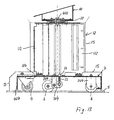
- an examination table 2 which is mounted in such a way as to be able to slide on wheels 3, 4 on a translation guide 5 which is integral with the machine 1, and oriented towards the axis of the tubular detection cavity 101, preferably and particularly being contained in the vertical plane which passes through the central axis of said detection cavity 101.
- the guide 5 has a predetermined length and is shaped so as to ensure that the shoes, or particularly the accordingly shaped wheel/s 6, which are provided in a corresponding position in a carriage 7 of the examination table, do not perform transversely staggered movements, but only one translation movement longitudinal to the guide.
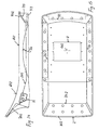
- the examination table consists of a supporting plane 102, having an upper hollow, in the form of a tub 202, of the type which flaringly tapers towards the bottom, and being meant to receive a rear projection, accordingly flared 108, of a mattress 8, there being provided removable means for fastening the mattress 8 to the supporting plane 102.
- These means may be of any type, for example in the form of snap fasteners, or consisting of fastening tapes of the type known under the name of Velcro, or similar.
- the total height of the examination table substantially corresponds to the height of the lower side of the detection cavity 101, there being provided that position tolerances with respect to height are positively uncritical for patient positioning, so that the patient is always able to introduce the limb to be examined into the detection cavity 101, while being in a lying position.
- the bearing plane 102 and, accordingly, the mattress 8 are concave, with the axis of curvature being transverse to the longitudinal extension of the examination table, and with the lower and curved zone being provided closer to one of the two examination table ends 2, i.e. the one which will be referred to, hereafter and in claims, as feet end.
- the bearing plane 102 and the mattress 8 are substantially straight, or slightly concavely curved, and are anyway oriented on a plane which is inclined with respect to the horizontal plane, in a rising direction towards the associated end.
- the examination table 102 has such a length that the feet end terminates substantially on the same level as a statistically intermediate point of the leg, particularly between the knee and the trunk. Obviously, the patient may be positioned either slightly staggered with respect to the feet end, or slightly staggered with respect to the head end, according to the type of limb to be examined.
- the feet end has two vertical legs 302, each having, at its end, a wheel 3, provided with brakes 103, and rotatable not only about a horizontal axis, but also about a vertical axis.
- the examination table i.e. the plane 102 is supported by a fulcrum 402, which coincides with the longitudinal median axis thereof, and around which the plane 102 may rotate about a vertical axis.
- a fulcrum 402 which coincides with the longitudinal median axis thereof, and around which the plane 102 may rotate about a vertical axis.
- An upper plate 10 is attached to the lower side of the bearing plane 102, or to a flange associated thereto, by means of a wedge-shaped spacer 11, which acts as a support, whose inclination corresponds to that provided for the bearing plane 102 in said attachment point.
- the other plate, the lower plate 9 is carried at the top of a vertical column 12, extending upwards from a lower carriage 7.
- the carriage 7 has two successive translation rollers in the median area and in line along the guide 5, said rollers being shaped so as to be complementary to the cross section of the guide.
- the rollers are supported, by an upper plate 107 of the carriage 7 through forks 207.
- the rollers may be also elastically supported by elastic means, for example springs 13, interposed between a support bracket 307, for example an equalizer or a bracket being able to swing or slide vertically and a matching member, integral with the plate 107.
- the springs 13 may be associated to means 14 for adjusting their preloading state, for example screw means for generating a certain precompression of the swinging arm 307 on the spring 14.
- the carriage 7 also has two transverse wings 407, which are substantially symmetrical with respect to the longitudinal median axis, each one bearing, at a certain distance from said axis and symmetrically thereto, one wheel 4, which is to touch the ground and to rotate both about a horizontal axis and about a vertical axis.
- the wheels 4 may be also provided with braking or locking means 104.
- the bearing plane 102, the carriage 7 and the column 12 all have a construction provided with an inner load bearing core, for example made of metal, like sheet metal, or similar, or of any material suiting its mechanical characteristics, said core having mounts 112 for fastening coverings or cases 15, made of a material unfit for bearing structures.
- an inner load bearing core for example made of metal, like sheet metal, or similar, or of any material suiting its mechanical characteristics, said core having mounts 112 for fastening coverings or cases 15, made of a material unfit for bearing structures.
- the bearing plane of the examination table also has a load bearing core 702, only shown by way of indication, which is covered by a case, providing it with the desired exterior shape.
- the bearing plane 102 has one mount for each side, for one armrest 17 respectively.
- the armrests consist of elements having an approximately trapezoid shape, when seen in a side view.
- the means for removable attachment thereof to the plane 102 of the examination table 2 consist of a pair of transverse pins 117, which are meant to engage in holes 116 matching the pins 16 on the sides of the plane 102 of the examination table.
- One pin being radially larger, acts as a support pin, and the other has the function to prevent the armrest 17 from rotating about the support pin.
- a footrest 20 is attached to the two legs 302 at the corners of the examination table end, associated to feet.
- the footrest is supported so as to overturn about a horizontal axis, between at least one outwardly projecting operating position, and an idle position, in which it is substantially parallel to the plane subtended by the two legs 302 of the examination table, or may be even retracted so as to be hidden in a recess formed between the two legs, and partially in the two legs 302, appropriately shaped.
- the footrest 20 is hinged about a horizontal axis, transverse to the longitudinal axis of the examination table 2, and located at an intermediate height between the ground and the plane 102.
- the height of the hinging axis is chosen in such a way that the patient may have his trunk laid, while the lower part of the leg, from the knee down, is substantially vertical and the foot rests on the footrest 20. This allows the patient to be in a relatively comfortable and stable position, i.e. with his body on the same axis as the detection cavity 5, when images of a foot region, or of the leg region below the knee are to be detected.
- the footrest 20 is turned to the idle position, allowing the examination table 2 to get closer to the machine 1, while the leg under examination rests on the structure of the machine 1, and the other leg is kept slightly bent in a relatively comfortable position, forming an inverted V, with the knee up, or kept sideways, in said inverted V position.
- the vertical position of the hinging axis may be easily adjustable, by providing that the hinge is mounted on a sliding saddle, and that it may be locked in its position in two lateral guides, each fixed to a leg 720.
- the hinging axis may be fixed, as in the present example.
- the footrest 20 has a central extension 120, forming a first fork 220, on the side designed to be jointed.
- the first fork 220 has, on its two branches, two through holes, for the passage of a horizontal and transverse hinging pin, which passes through coincident holes formed on the two branches of a second fork 802, projecting out of the examination table end 102, and whose branches superpose the inner faces of the two branches of the first fork 220.
- the latter have means for attachment to the branches of the second fork 802, for example pins or pegs, schematically shown by their axis, indicated as 23, the hole for the passage of the hinging pin 21 and a hole 24, at a predetermined radial and angular distance from the hinging axis 21, for engaging a locking tooth or pin 25, which is alternately movable in the axial direction of the hole 24 to a position in which it is retracted from the hole 24 and to a position in which it is engaged in the hole 24, said engagement position corresponding the footrest 20 being locked in the outwardly overturned operating position.
- pins or pegs schematically shown by their axis, indicated as 23, the hole for the passage of the hinging pin 21 and a hole 24, at a predetermined radial and angular distance from the hinging axis 21, for engaging a locking tooth or pin 25, which is alternately movable in the axial direction of the hole 24 to a position in which it is retracted from the hole 24 and to a position in which it
- the locking pin 25 is slidably supported in a tubular guide 26, integral with the corresponding branch of the first fork 220, and is subject to the action of an elastic member, preferably a spring 27, which stably pushes it into the position in which it is retracted from the hole 24, and against a retraction end-of-stroke matching member 28.
- the latter extends beyond the diameter of the pin and forms, together with an annular enlarged wall, a guide for a driving rod 29, which has, at its free end, a wedge-shaped surface having the function of a cam 129.
- the rod 29 extends up to the lateral area of the footrest 20, which is shaped like a box, and the end opposite to the cam 129 is jointed into an intermediate point of an operating lever 30, whose fulcrum 31 corresponds to its end inside the footrest 20, whereas it projects by a driving button or shaped end, at its free end, into a lateral niche 320 of the footrest 20.
- the lever 30, and thereafter the rod 29 and the cam 120 are stably pushed into the position in which the pin 25 is engaged in the hole 24 against the action of the spring 27, by another spring 32.
- the lever 30 need only be driven to disengage the locking pin 25 from the hole 24, in order to unlock the footrest 20 from the operating position, and to bring it into the inwardly turned idle position, against the legs 302.
- the figures show another characteristic, consisting in that the plane 102 of the examination table 2 has several cavities, recesses or niches, both on its ends and sides. These hollows are indicated as 35, 36 and handle elements 33 are fastened thereat.
- the handle elements 33 and the niches 35, 36 are so shaped that the former may be easily and comfortably grasped, although they do not protrude or project out of the space occupied by the plane 102, unless to an insignificant extent.
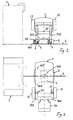
- Figs. 2 and 3 and 4 and 5 show the potentialities and functions of the examination table according to the invention.
- the examination table is oriented transverse, particularly perpendicular to the axis of the detection cavity 101, and hence of the translation guide 5.
- the footrest 20 may be set in any position, as the patient desires.
- This arrangement of the examination table is particularly recommended for the treatment of arms and hands.
- a part of the patient body comfortably lays on the examination table, whereas the arm to be treated, or the one associated to the hand to be treated, is outwardly oriented, in the natural position in which it is held out transverse to the body, which position is also substantially on the same axis as the detection cavity 101. So, the patient takes a perfectly comfortable position, corresponding to the functional characteristics of the limb.
- the introduction and the extraction of the arm into and from the detection cavity 101 is simply obtained by translating the examination table 2 along the guide 5. Thanks to the fact that the examination table 2 may be rotated about the vertical axis 102, the orientation of the examination table 2 may be adjusted with respect to that of the detection cavity 101 without interruption and in such a way as to obtain the best patient positioning.
- the examination table 2 In order to detect images of one leg or parts thereof, the examination table 2 is rotated until its longitudinal axis takes a position substantially parallel to the axis of the detection cavity 101. In this position, the patient, on the examination table 2 is oriented in such a way that his legs are substantially aligned with the detection cavity 101. The leg is introduced in the correct position into the detection cavity 101 and extracted therefrom, by a translation movement along the guide 5. This case also provides that the examination table 2 may be angularly displaced to be adjusted with respect to the axis of the detection cavity 101.
- the footrest 20 is in the operating position, or turned to the idle position.
- the footrest 20 may be kept in the operating position when a foot or a heel are to be examined.
- the footrest is to be brought to the idle position, so that the examination table may be further approached to the opening of the detection cavity 101.
Landscapes
- Health & Medical Sciences (AREA)
- Life Sciences & Earth Sciences (AREA)
- Physics & Mathematics (AREA)
- Molecular Biology (AREA)
- Heart & Thoracic Surgery (AREA)
- Nuclear Medicine, Radiotherapy & Molecular Imaging (AREA)
- Biophysics (AREA)
- Pathology (AREA)
- Engineering & Computer Science (AREA)
- Biomedical Technology (AREA)
- Veterinary Medicine (AREA)
- Medical Informatics (AREA)
- Public Health (AREA)
- Surgery (AREA)
- Animal Behavior & Ethology (AREA)
- General Health & Medical Sciences (AREA)
- High Energy & Nuclear Physics (AREA)
- Radiology & Medical Imaging (AREA)
- Magnetic Resonance Imaging Apparatus (AREA)
Description
Claims (18)
- An examination table, particularly in Nuclear Magnetic Resonance image detecting machines of the so-called dedicated type, i.e. designed for detecting images of specific body parts, the examination table (2) having an at least one-degree-of-freedom constraint (5, 6) to the machine (1), and support means (6, 7, 12, 402, 302) which allow the examination table (2) to be moved in at least one, preferably two or more degrees of freedom,
the examination table being mounted in such a way as to be able to slide (7, 6) on a stationary guide (5) which is fixed with a predetermined orientation with respect to a detection cavity (101) of the machine (1) and it may be further translated in both senses along said guide (5) and rotated (11, 12) about a vertical axis (402) of rotation perpendicular to the direction it follows while sliding on the guide (5),
the support means comprising a point of support, coinciding with the said vertical axis of rotation (402) which corresponds to the median longitudinal axis at the opposite end side of the examination table (2),
characterized in that
the examination table has supporting means with three points of support, comprising further two wheels (302), which coincide with two corners of one end side of the examination table said wheels (3) being also rotatable about a vertical axis, - An examination table as claimed in claim 1, characterized in that the stationary guide (5) is for rectilinear translation and is oriented in the direction of insertion/extraction of one part of the patient body in or from the detection cavity (101) by a simple straight-line translation movement, while the examination table (2) may be also rotated (11, 12) about an axis perpendicular to said translation direction.
- An examination table as claimed in claim 2, characterized in that the stationary guide (5) is horizontal, while the axis of rotation (402) of the examination table is vertical.
- An examination table as claimed in claim 1, characterized in that the vertical axis of rotation (402) is provided at the top of a supporting column (12), which has a lower carriage (7) with at least three points of support, i.e. at least one central sliding wheel (6), associated to the stationary guide (5), and at least two lateral wheels (4), touching the ground, and being also rotatable about a vertical axis.
- An examination table as claimed in claim 4, characterized in that there are at least two wheels (6) associated to the stationary guide (5), aligned one behind the other in the median vertical plane of the examination table (2).
- An examination table as claimed in one or more of the preceding claims, characterized in that it has a stationary part (102), whose length substantially corresponds to the average length of the human trunk, and an overturning extension (20), provided at one end, having the function of a footrest, which footrest (20) can be alternately overturned and locked, by removable locking means (23, 24, 25, 26, 27, 28, 29, 30, 31, 32), into a projecting position, in which it extends the examination table (2), and into a rest position, in which it is substantially parallel to, or possibly partially hidden along the corresponding end side of the examination table (2). '
- An examination table as claimed in one or more of the preceding claims, characterized in that it is anatomically curved, the curved region (602) being moved towards the end side with the two wheels (3), i.e. in the area intended to receive the pelvis.
- An examination table as claimed in claim 6 or 7, characterized in that the said stationary part (102) forms a bearing plane of the examination table (2) and has, at its top, the form of a tub (202), there being provided a mattress (8), which is shaped so as to correspond to the said bearing plane and said mattress (8) has a projection (108) on the bottom side, whose shape and size substantially correspond to the upper tub-like hollow (202) of the said bearing plane.
- An examination table as claimed in one or more of the preceding claims, characterized in that it has at least one, preferably a pair of armrests (17), removably mounted (116, 117) on each side of the examination table (2).
- An examination table as claimed in claim 9, characterized in that each armrest has a pair of supporting pins (117), which are meant to be inserted in corresponding holes (116) of an attachment plate (16) on each side wall of the said stationary part (102).
- An examination table as claimed in claims 9 or 10, characterized in that the armrests (17) are provided on the two sides of the pelvis area, i.e. at the curved zone (602) of the said stationary port (102).
- An examination table as claimed in one or more of the preceding claims, characterized in that the vertical axis of rotation (402) of the examination table (2), corresponding to the third point of support thereof, is located in the area of the examination table (2), which is associated to the upper back, while the opposite end side has two legs (302) each at one corner, a footrest (20) being provided which is hinged between, the said two legs (302) and said end side being provided substantially at the knees.
- An examination table as claimed in one or more of the preceding claims 7 to 12, characterized in that the stationary part (102) of the examination table has a substantially plane back-supporting part extending with a predetermined inclination with respect to the wholly horizontal orientation, i.e. with a rising inclination from the lowest zone of the hollow formed by the said curved region (602).
- An examination table as claimed in claim 13, characterized in that opposite to the plane back-supporting part as much shorter branch, associated to legs (302) is provided which branch being, provided with the overturning footrest (20) and being also oriented with a certain rising inclination towards the end side of the examination table (2) associated thereto.
- An examination table as claimed in the preceding claims 8 to 14 characterized in that the footrest (20) is located at an intermediate height with respect to the said bearing plane of the examination table, so that the patient may lay his feet thereon, while laying and with bent knees.
- An examination table as claimed in one or more of the preceding claims, characterized in that it has a core made of bearing and rigid material, particularly of metal (702, 112, 107), having covering elements (15) being mounted thereon, with different exterior shapes and functions (35, 36).
- An examination table as claimed in one or more of the preceding claims, characterized in that it may take two angular positions, rotated 90° with respect to each other and with respect to the stationary guide (5) for moving in the direction of insertion/extraction of the body part in or from the said detection cavity (101), in which two positions the longitudinal axis of the examination table is substantially parallel to the said stationary guide (5) , or transverse, substantially perpendicular to said stationary guide (5), the former position being used for detecting images of one or both legs, and the latter being used for detecting images of one or both arms, or parts thereof, said, arms being disposed, in the second position, perpendicular to the trunk.
- An examination table as claimed in one or more of the preceding claims, and in combination with a machine (1) for detecting Nuclear Magnetic Resonance images, characterized in that the machine has a tubular detection cavity (101), the stationary guide (5) being aligned with the central axis of the said cavity (101) on the same vertical plane.
Applications Claiming Priority (2)
| Application Number | Priority Date | Filing Date | Title |
|---|---|---|---|
| IT97SV000040A IT1298015B1 (en) | 1997-09-16 | 1997-09-16 | TABLE IN PARTICULAR IN MACHINES FOR IMAGE DETECTION IN NUCLEAR MAGNETIC RESONANCE. |
| ITSV970040 | 1997-09-16 |
Publications (2)
| Publication Number | Publication Date |
|---|---|
| EP0913122A1 EP0913122A1 (en) | 1999-05-06 |
| EP0913122B1 true EP0913122B1 (en) | 2005-04-20 |
Family
ID=11408236
Family Applications (1)
| Application Number | Title | Priority Date | Filing Date |
|---|---|---|---|
| EP98116280A Expired - Lifetime EP0913122B1 (en) | 1997-09-16 | 1998-08-28 | Examination table, particularly in machines for nuclear magnetic resonance image detection |
Country Status (5)
| Country | Link |
|---|---|
| US (2) | US6345193B2 (en) |
| EP (1) | EP0913122B1 (en) |
| DE (1) | DE69829820T2 (en) |
| ES (1) | ES2236852T3 (en) |
| IT (1) | IT1298015B1 (en) |
Cited By (1)
| Publication number | Priority date | Publication date | Assignee | Title |
|---|---|---|---|---|
| EP1262145B2 (en) † | 2001-05-28 | 2011-07-06 | Esaote S.p.A. | Apparatus for imaging the inner part of a body |
Families Citing this family (28)
| Publication number | Priority date | Publication date | Assignee | Title |
|---|---|---|---|---|
| DE19940778B4 (en) | 1999-08-27 | 2005-12-22 | Bruker Biospin Mri Gmbh | Apparatus for performing nuclear magnetic resonance measurements on a body part of a large animal |
| DE10114013B4 (en) * | 2001-03-22 | 2005-06-23 | Siemens Ag | magnetic resonance system |
| ITSV20010020A1 (en) * | 2001-06-08 | 2002-12-08 | Esaote Spa | MACHINE FOR THE ACQUISITION OF IMAGES OF THE INTERNAL AREA OF A BODY IN PARTICULAR FOR THE ACQUISITION OF DIAGNOSTIC IMAGES |
| US6934574B1 (en) | 2001-06-21 | 2005-08-23 | Fonar Corporation | MRI scanner and method for modular patient handling |
| US6776527B1 (en) * | 2001-07-16 | 2004-08-17 | Analogic Corporation | Patient table docking system and method for tomography scanners |
| US6944492B1 (en) * | 2001-10-01 | 2005-09-13 | Fonar Corporation | Patient bed support for an open MRI system |
| US10213168B2 (en) * | 2003-03-07 | 2019-02-26 | Siemens Medical Solutions Usa, Inc. | Reclining patient chair for nuclear medicine system |
| EP1495718B1 (en) * | 2003-07-11 | 2006-06-14 | Esaote S.p.A. | Apparatus for magnetic resonance imaging |
| US6971132B2 (en) * | 2003-09-16 | 2005-12-06 | Feinsod Fred M | Mattress with hand supports |
| US20050066861A1 (en) * | 2003-09-29 | 2005-03-31 | The Brewer Company, Llc | Lifting column for a medical examination table |
| US7083355B2 (en) | 2003-09-29 | 2006-08-01 | The Brewer Company, Llc | Stirrup support indexer for a medical examination table |
| US7350249B2 (en) | 2003-09-29 | 2008-04-01 | The Brewer Company, Llc | Leg rest and kneeler assembly for a medical examination table |
| US7093313B2 (en) | 2003-09-29 | 2006-08-22 | The Brewer Company, Llc | Headrest linkage |
| DE102005034159A1 (en) * | 2005-07-21 | 2007-02-01 | Siemens Ag | Patient table and computed tomography device comprising a patent table |
| USD569520S1 (en) | 2005-07-28 | 2008-05-20 | Debraal Jack A | Medical examination table cabinet |
| USD574960S1 (en) | 2005-07-28 | 2008-08-12 | Parrish Vanessa B | Medical examination table top |
| US7513000B2 (en) | 2005-07-28 | 2009-04-07 | The Brewer Company, Llc | Medical examination table |
| USD535544S1 (en) | 2005-07-28 | 2007-01-23 | The Brewer Company, Llc | Grab bar |
| USD574959S1 (en) | 2005-07-28 | 2008-08-12 | Debraal Jack A | Medical examination table |
| US9038216B2 (en) | 2005-07-28 | 2015-05-26 | The Brewer Company, Llc | Medical examination table |
| US20080039714A1 (en) * | 2006-08-08 | 2008-02-14 | Intermagnetics General Corporation | Magnetic resonance imaging system, a gradient coil, and a method of using the system |
| US20080125641A1 (en) * | 2006-08-08 | 2008-05-29 | Intermagnetics General Corporation | Seat, a chair including a seat, and a method of using a magnetic resonance imaging system including a seat |
| ATE418738T1 (en) | 2006-09-29 | 2009-01-15 | Esaote Spa | MAGNETIC RESONANCE IMAGING DEVICE AND MAGNETIC RESONANCE IMAGING METHOD USING SUCH DEVICE |
| JP4924672B2 (en) * | 2008-07-23 | 2012-04-25 | 株式会社デンソー | Rotation detection device signal processing circuit |
| US20120084919A1 (en) * | 2010-10-09 | 2012-04-12 | Fmi Technologies, Inc. | Patient positioning apparatus |
| CN103040482A (en) * | 2011-10-09 | 2013-04-17 | 明峰医疗系统股份有限公司 | Patient positioning apparatus |
| US9572516B1 (en) * | 2013-08-06 | 2017-02-21 | Babak Sheikh | Application and method for producing images of moving joints |
| CN118236058B (en) * | 2024-05-28 | 2024-08-30 | 默拓(江苏)电气驱动技术有限公司 | Driving device for nuclear magnetic resonance lifting table |
Family Cites Families (8)
| Publication number | Priority date | Publication date | Assignee | Title |
|---|---|---|---|---|
| SE462013B (en) | 1984-01-26 | 1990-04-30 | Kjell Olov Torgny Lindstroem | TREATMENT TABLE FOR RADIOTHERAPY OF PATIENTS |
| US4681308A (en) | 1985-07-16 | 1987-07-21 | Paul Rice | Diagnostic patient support apparatus |
| JPH01209053A (en) | 1988-02-17 | 1989-08-22 | Hitachi Ltd | Patient table installing mechanism for mr imaging device |
| JPH0217038A (en) | 1988-07-06 | 1990-01-22 | Toshiba Corp | Magnetic resonance imaging apparatus |
| US6044289A (en) * | 1991-12-04 | 2000-03-28 | Bonutti; Peter M. | Apparatus and method for controlling bending of a joint of a patient during imaging |
| US5305749B1 (en) * | 1992-09-24 | 2000-05-02 | Univ California | Side-loading of patient into mri c-magnet while maintaining adjacent open accessibility to patient |
| US5735278A (en) * | 1996-03-15 | 1998-04-07 | National Research Council Of Canada | Surgical procedure with magnetic resonance imaging |
| IT1306601B1 (en) * | 1996-08-22 | 2001-06-18 | Esaote Spa | ELECTROMAGNETIC SHIELDING ARRANGEMENT FOR NUCLEAR MAGNETIC ARISONANCE EQUIPMENT |
-
1997
- 1997-09-16 IT IT97SV000040A patent/IT1298015B1/en active IP Right Grant
-
1998
- 1998-08-27 US US09/141,260 patent/US6345193B2/en not_active Expired - Lifetime
- 1998-08-28 ES ES98116280T patent/ES2236852T3/en not_active Expired - Lifetime
- 1998-08-28 DE DE69829820T patent/DE69829820T2/en not_active Expired - Lifetime
- 1998-08-28 EP EP98116280A patent/EP0913122B1/en not_active Expired - Lifetime
-
2001
- 2001-11-07 US US09/986,169 patent/US6374133B1/en not_active Expired - Lifetime
Cited By (1)
| Publication number | Priority date | Publication date | Assignee | Title |
|---|---|---|---|---|
| EP1262145B2 (en) † | 2001-05-28 | 2011-07-06 | Esaote S.p.A. | Apparatus for imaging the inner part of a body |
Also Published As
| Publication number | Publication date |
|---|---|
| DE69829820D1 (en) | 2005-05-25 |
| EP0913122A1 (en) | 1999-05-06 |
| IT1298015B1 (en) | 1999-12-20 |
| ES2236852T3 (en) | 2005-07-16 |
| US6374133B1 (en) | 2002-04-16 |
| US20010003789A1 (en) | 2001-06-14 |
| ITSV970040A1 (en) | 1999-03-16 |
| ITSV970040A0 (en) | 1997-09-16 |
| DE69829820T2 (en) | 2006-03-02 |
| US20020028992A1 (en) | 2002-03-07 |
| US6345193B2 (en) | 2002-02-05 |
Similar Documents
| Publication | Publication Date | Title |
|---|---|---|
| US6345193B2 (en) | Examination table, particularly in machines for nuclear magnetic resonance image detection | |
| US9888865B2 (en) | Magnetic resonance imaging apparatus | |
| US6802564B2 (en) | Examination and treatment chair | |
| EP2450019B1 (en) | Siderail assembly for patient support apparatus | |
| US4541622A (en) | Reclining bed for childbirth | |
| EP0984293B1 (en) | Nuclear magnetic resonance imaging apparatus | |
| FI77570B (en) | FOERFARANDE OCH ANORDNING FOER ATT UTAN TUNGA LYFT FOERA EN ROERELSEHAEMMAD PERSON FRAON SITTANDE TILL LIGGANDE STAELLNING. | |
| US4865382A (en) | Surgeon's operating stool | |
| JP3821560B2 (en) | Medical table | |
| US5829766A (en) | Device for dressing and undressing and for the cleaning and care of the body of a handicapped person | |
| CN107809991B (en) | Medical and/or nursing beds and side rails therefor | |
| KR101982873B1 (en) | Exercise appartus with prone position | |
| JP2011156255A (en) | Chairing appliance | |
| JP2017047091A (en) | Transfer car | |
| JP4504176B2 (en) | Wheelchair for bathing | |
| CN212382894U (en) | Multifunctional anorectal operating bed | |
| JP6628463B1 (en) | Defecation support device for Western toilets | |
| CN212261821U (en) | A special chair for thoracocentesis | |
| CA1232102A (en) | Reclining bed for childbirth | |
| WO1989007432A1 (en) | Transport chair for disabled persons | |
| CN223627714U (en) | A shifting machine that can open at an angle | |
| JP2960718B1 (en) | Bath stretcher | |
| JP3986605B2 (en) | Bath chair for care recipient | |
| JPS639867B2 (en) | ||
| JP3533331B2 (en) | Gynecological angry grip device |
Legal Events
| Date | Code | Title | Description |
|---|---|---|---|
| PUAI | Public reference made under article 153(3) epc to a published international application that has entered the european phase |
Free format text: ORIGINAL CODE: 0009012 |
|
| AK | Designated contracting states |
Kind code of ref document: A1 Designated state(s): DE ES FR GB IT |
|
| AX | Request for extension of the european patent |
Free format text: AL;LT;LV;MK;RO;SI |
|
| 17P | Request for examination filed |
Effective date: 19991105 |
|
| AKX | Designation fees paid |
Free format text: DE ES FR GB IT |
|
| 17Q | First examination report despatched |
Effective date: 20031223 |
|
| GRAP | Despatch of communication of intention to grant a patent |
Free format text: ORIGINAL CODE: EPIDOSNIGR1 |
|
| GRAS | Grant fee paid |
Free format text: ORIGINAL CODE: EPIDOSNIGR3 |
|
| GRAA | (expected) grant |
Free format text: ORIGINAL CODE: 0009210 |
|
| AK | Designated contracting states |
Kind code of ref document: B1 Designated state(s): DE ES FR GB IT |
|
| REG | Reference to a national code |
Ref country code: GB Ref legal event code: FG4D |
|
| REF | Corresponds to: |
Ref document number: 69829820 Country of ref document: DE Date of ref document: 20050525 Kind code of ref document: P |
|
| REG | Reference to a national code |
Ref country code: ES Ref legal event code: FG2A Ref document number: 2236852 Country of ref document: ES Kind code of ref document: T3 |
|
| PG25 | Lapsed in a contracting state [announced via postgrant information from national office to epo] |
Ref country code: IT Free format text: LAPSE BECAUSE OF NON-PAYMENT OF DUE FEES Effective date: 20050828 |
|
| PLBE | No opposition filed within time limit |
Free format text: ORIGINAL CODE: 0009261 |
|
| STAA | Information on the status of an ep patent application or granted ep patent |
Free format text: STATUS: NO OPPOSITION FILED WITHIN TIME LIMIT |
|
| ET | Fr: translation filed | ||
| 26N | No opposition filed |
Effective date: 20060123 |
|
| REG | Reference to a national code |
Ref country code: FR Ref legal event code: CA |
|
| PGRI | Patent reinstated in contracting state [announced from national office to epo] |
Ref country code: IT Effective date: 20091201 |
|
| PGFP | Annual fee paid to national office [announced via postgrant information from national office to epo] |
Ref country code: ES Payment date: 20100730 Year of fee payment: 13 |
|
| PGFP | Annual fee paid to national office [announced via postgrant information from national office to epo] |
Ref country code: FR Payment date: 20100915 Year of fee payment: 13 |
|
| PGFP | Annual fee paid to national office [announced via postgrant information from national office to epo] |
Ref country code: GB Payment date: 20100728 Year of fee payment: 13 |
|
| GBPC | Gb: european patent ceased through non-payment of renewal fee |
Effective date: 20110828 |
|
| REG | Reference to a national code |
Ref country code: FR Ref legal event code: ST Effective date: 20120430 |
|
| PG25 | Lapsed in a contracting state [announced via postgrant information from national office to epo] |
Ref country code: FR Free format text: LAPSE BECAUSE OF NON-PAYMENT OF DUE FEES Effective date: 20110831 Ref country code: GB Free format text: LAPSE BECAUSE OF NON-PAYMENT OF DUE FEES Effective date: 20110828 |
|
| REG | Reference to a national code |
Ref country code: ES Ref legal event code: FD2A Effective date: 20130604 |
|
| PG25 | Lapsed in a contracting state [announced via postgrant information from national office to epo] |
Ref country code: ES Free format text: LAPSE BECAUSE OF NON-PAYMENT OF DUE FEES Effective date: 20110829 |
|
| REG | Reference to a national code |
Ref country code: DE Ref legal event code: R082 Ref document number: 69829820 Country of ref document: DE Representative=s name: BISCHOF & PARTNER RECHTSANWAELTE PARTNERSCHAFT, DE |
|
| PGFP | Annual fee paid to national office [announced via postgrant information from national office to epo] |
Ref country code: IT Payment date: 20170728 Year of fee payment: 20 Ref country code: DE Payment date: 20170731 Year of fee payment: 20 |
|
| REG | Reference to a national code |
Ref country code: DE Ref legal event code: R071 Ref document number: 69829820 Country of ref document: DE |