EP0912324B1 - Process for making an optical disc master - Google Patents
Process for making an optical disc master Download PDFInfo
- Publication number
- EP0912324B1 EP0912324B1 EP96924464A EP96924464A EP0912324B1 EP 0912324 B1 EP0912324 B1 EP 0912324B1 EP 96924464 A EP96924464 A EP 96924464A EP 96924464 A EP96924464 A EP 96924464A EP 0912324 B1 EP0912324 B1 EP 0912324B1
- Authority
- EP
- European Patent Office
- Prior art keywords
- lamina
- disc
- partially reflective
- pits
- laser
- Prior art date
- Legal status (The legal status is an assumption and is not a legal conclusion. Google has not performed a legal analysis and makes no representation as to the accuracy of the status listed.)
- Expired - Lifetime
Links
Images


Classifications
-
- G—PHYSICS
- G11—INFORMATION STORAGE
- G11B—INFORMATION STORAGE BASED ON RELATIVE MOVEMENT BETWEEN RECORD CARRIER AND TRANSDUCER
- G11B7/00—Recording or reproducing by optical means, e.g. recording using a thermal beam of optical radiation by modifying optical properties or the physical structure, reproducing using an optical beam at lower power by sensing optical properties; Record carriers therefor
- G11B7/24—Record carriers characterised by shape, structure or physical properties, or by the selection of the material
- G11B7/26—Apparatus or processes specially adapted for the manufacture of record carriers
- G11B7/261—Preparing a master, e.g. exposing photoresist, electroforming
Definitions
- This invention relates to a process for making an optical disc master.
- Optical disc (OD) Masters are articles from which prerecorded mass produced consumer OD's are subsequently molded.
- the master is a first article in the OD manufacturing process having data or information recorded on a disc or platter that can be read by optical means. All subsequent OD manufacturing and duplication processes transfer that identical form, format and data from the original first article by various means including: vacuum deposition; electroforming/plating; or injection molding processes.
- Past techniques for producing masters combined existing technologies from various industries. The most prominent of these techniques is the photo resist concept of the semiconductor industry.
- the master had formed on it a series of pits which serve to optically record information.
- the pits form a spiral line or track starting at a central portion of the disc and continuing to the outer periphery of the disc.
- the pits are approximately 0.6 um (10 -8 meters) wide, 0.9 to 3.3. um long, 0.12 um deep, and are separated from neighborhood tracks, on either side thereof, by 1.6 um center to center.
- a lamina of photoresist material is spun upon a very smooth, polished circular plate of glass.
- the glass plate with photoresist lamina is then placed in an oven to cure the photoresist.
- the cured, photoresist coated, glass plate is next set upon a turntable which is caused to spin.
- a data modulated laser optical system is focused on the glass plate, while suspended by a relatively large and complex translational mechanism, to cause the focused spot laser to move very gradually, at a steady radial rate, outwardly from the center of the spinning glass plate while concomitantly radiating the surface of the plate. The affect being to produce a spiral track of data in the photoresist material.
- the turntable spins at either a constant angular velocity (CAV) or a constant linear velocity (CLV) while any point on the surface of the plate is being radiated by a laser.
- CAV constant angular velocity
- CLV constant linear velocity
- This process is referred to as mastering, wherein, data is recorded by creating pits in the optical disc from the exposure to laser light along the spiral path as the plate rotates.
- the plate is placed in at least one bath of developing solution, typically a process that requires multiple steps, whereby, the exposed areas in the photoresist are etched out leaving a series of pits.
- the glass plate with etched photoresist is then oven dried, followed by metalization of the photoresist lamina by vacuum deposition of a thin conductive lamina of metal thereon, which yields the desired master.
- the master is finally subjected to an analysis and validation process prior to electroforming to make a stamper and replication.
- the foregoing type of mastering system is quite expensive in terms of capital equipment involved, labor, space, sensitivity to motion and shock, time and costs. Operating costs to produce a single master can be relatively expensive.
- NPR non-photo resist
- DPF dry process formula
- DMM direct metal mastering
- a major objective in recording optical disc masters is to control the geometry of the pits used to record data on the disc. Poor pit geometry makes the separation of duplicate discs from the disc stampers difficult. Also, data transmission can be affected by pits having raised areas surrounding the pit called berms, which are a common result in the dry process formula (DPF).
- An ideal pit is one formed with a complementary surrounding area.
- Much modem research and development has been devoted to creating recorded optical discs having ideal pit shapes.
- some of the conventional techniques, discussed above have not developed a manner of recording optical discs without generating the variable berm areas surrounding the pits used to record data.
- Applicant's earlier invention covered under US Patent 5,283,159 addressed improved pit formation and the berm build up problem in optical disc mastering by application of a semi transparent, very thin, metallic, thermo conductive layer for dissipation of heat accumulation around a pit at the moment of pit creation.
- a semi transparent, very thin, metallic, thermo conductive layer for dissipation of heat accumulation around a pit at the moment of pit creation.
- the present invention provides a process for making an optical disc master from which an optical disc stamper can be made, characterised by the features of claim 1.
- the invention provides a process useful in recording data on and in the manufacture of optical discs, wherein, laser tracking is improved and pits, used to record data, have their geometry and berm buildup controlled in a simple, effective and inexpensive manner.
- the invention utilizes an optically transparent (either polycarbonate or glass) disc substrate having an optical tracking groove molded or etched on a side, thereof. While in a cleanroom environment, a very thin layer (on the order of 30 to 50 Angstroms) of a substrate having different optical characteristics from that of the disc substrate is applied to the grooved side of the substrate, such that partial reflectivity is obtained.
- An optically active lamina is then spin coated on top the partially reflective layer.
- the active lamina is encoded with data by laser means configured to focus a data modulated beam along the tracking groove causing ablation andlor consumption of the optically active lamina.
- the partially reflective layer has an index of refraction that is different from either the disc substrate or the optically active lamina, which both have a similar index of refraction.
- a laser can more effectively track the junction area between the optically transparent disc substrate and optically active lamina layer due to the optical feedback received from partially reflective layer.
- the desired pit size and geometry is achieved by selecting the laser power in conjunction with the thickness of the partially reflective layer.
- the partially reflective layer affects the characteristics of the exothermic reaction when the optically active lamina is subjected to a focused laser. While the laser is focused on optically active lamina creating heat, the partially reflective layer will also be focused on by the laser, and will cause additional heat to be generated. These effects have shown in related tests to result in a pit geometry that is virtually ideal.
- An ideal pit is one that has limited variability in berms or raised areas immediately surrounding the pit. The cause of these berms is not positively known, although is thought that these berm raised areas are caused by a failure to ablate all of optically active lamina from the circumferential portions of desired pit area or due to heat build up around the periphery of each pit.
- an additional step of Ultra Violet (UV) Curing of the reactive layer is utilized. After data is recorded, i.e. after pit creation, the reactive layer is subjected to one or more passes under or through a high intensity UV light. The UV curing step tends to level out if not totally eradicate the undesirable berm typically associated with laser pit formation.
- UV Ultra Violet
- Another object of the invention is to provide a fast and inexpensive method of recording data in a controlled manner on optical discs.
- Another object of the invention is to disclose an OD Mastering system capable of improved pit geometry and increased laser tracking that uses commercially available optical head, laser means and optically transparent substrate to avoid the need for expensive capital equipment found in prior OD Mastering systems.
- Another object of the invention is to provide improved pit formation on optical discs by increasing the tracking and focusing potential for disc substrates such that a data modulated laser beam may accurately be focused upon and radiate from either side of the disc and cause improved consumption, ablation and sublimation of the optically active layer.
- Yet another object of the invention is to lower operating expenses encountered in producing an optical disc recording or an OD Master having ideal pit geometry's and increased laser tracking.
- the following description is provided in order to enable any person skilled in the arts of optical disc mastering and optical disc recordings to make and use the invention, and sets forth the best modes contemplated by the inventors for carrying out the invention.
- the invention as disclosed, herein, can be used with a variety of embodiments. There are three categories that determine the various embodiments that can possibly be used with the invention.
- the first category concerns optical backing paths.
- the present invention can be embodied on optical recording disc substrates with a raised optical tracking path as well as those that are flat and without any tracking path.
- the specific embodiments necessary for systems that record optical disc masters using discs substrates having an optical tracking path differ from those systems that record on disc substrates with no optical tracking path.
- the second category relates to recording data on either a first (external lamina/layer) surface or a second surface of the optical disc.
- the present invention is useful in systems that focus a laser directly on a first surface upon which laser light is incident as well as for systems that focus laser light through the disc on a second inner lamina/layer surface to record data.
- the third category relates to systems employing a glass disc substrate instead of those that employ a plastic disc substrate. Again, the invention is useful in embodiments employing either a glass or plastic substrate.
- the various combinations of these three categories yields eight (8) types of embodiments that are possible with the present invention. Only those embodiments most preferred by the inventors shall be discussed herein.
- FIG. 1 an illustration of disc 1 is typical of an unrecorded optical disc manufactured according to the concepts of the present invention.
- Fig. 2 illustrates a cross-sectional view of disc 1 as seen in Fig. 1 along the plane defined by the diameter and displays the various layers on disc 1 that constitute the present invention.
- a partially reflective layer 16 is deposited on top of disc substrate 10 on the surface of disc 1 used to record data.
- An optically active layer 18 is formed immediately on top of partially reflective layer 16.
- the novel placement of partially reflective layer 16 is an essential feature of one embodiment of the invention since it provides increased reflectance useful in laser tracking. Additionally, it has been discovered that partially reflective layer 16 provides a means of controlling the geometry of the pits used to record data within optically active lamina 18.
- An alternate, second embodiment utilizes no reflective, thermo conductive layer whatsoever.
- Partially reflective layer 16 is formed by taking a material that is normally considered opaque and applying such an extremely thin layer on to disc substrate 10 that partially reflective 16 reflects and absorbs only a very small percentage of incident light.
- the extreme thinness of partially reflective layer 16 is also an essential part of the present invention. By applying partially reflective layer 16 in a layer having a thickness measured in tens of A, most of the incident light can pass through partially reflective layer 16. However, a small percentage, on the order of one percent, of the incident light will be reflected or absorbed.
- Optically active lamina 18 is used to store data on optical disc 1 as pits formed within optically active lamina 18 as a result of irradiation from laser light.
- the use of an optically active lamina to store data in an optical disc is well known to art of optical disc mastering.
- One feature of the present invention is the use of partially reflective layer 16 to improve laser tracking and control of pit geometry.
- the presence of partially reflective layer 16 assists to improve laser tracking and control of pit geometry.
- the presence of partially reflective layer 16 provides an additional junction for laser beam focusing; a useful feature in both read and write modes. By having light pass through mediums of differing refractive indices, a reflection of the incident light occurs at each junction.
- partially reflective layer 16 assists in the formation of pits within optically active lamina 18 that are ideal in shape, having little or no raised areas surrounding the pit, but instead, have virtually all of optically active lamina 18 removed from the pit target area by a combination of ablation, consumption and/or sublimation.
- These ideal pit shapes are especially useful in mass production of duplicate optical discs from the resulting optical disc master due to the attenuation if not total elimination of the raised "berm" areas surrounding the pits which would otherwise cause complications in the manufacturing process.
- Disc substrate 10 can have either an optical tracking path molded in, etched on the writing surface or may simply be a flat/planar disc depending on the specific embodiment.
- Disc substrate can be either transparent polycarbonate, a transparent polymethylmethacrylate (PMMA) or any other transparent substrate capable of carrying a tracking path. Glass would suffice for those embodiments employing an optical tracking path.
- Transparency of disc 10 is not an essential ingredient to the present invention in those embodiments where recording is accomplished by focusing a laser on the first surface of the disc to record data.
- Conventional mastering techniques used in the optical disc industry write to optical disc surfaces without focusing through the disc substrates. The present invention is equally useful for those conventional systems as well as embodiments where the laser focuses through transparent disc 10 and reflective layer 16, and onto reactive layer 18 as illustrated in Fig. 5.
- FIG. 3 a diagram of pits created using conventional disc mastering techniques employing optical disc 30 substrate having an optically active lamina 38 applied to the disc surface.
- the pits 34 indicated by the dotted line, that result from laser irradiation of optically active lamina 38 have berms 36 surrounding the pit 34. These berms result in undesirable problems in laser tracking and especially in reproducing the recorded disc that has these defects. Berms in a master disc create a situation where it is difficult to separate the duplicate copies from a mold, which in turn makes mass production difficult.
- One method as seen in Fig. 4 employs a partially reflective layer 16 to create pits 24, indicated by the dotted line, within optically active lamina 18 with nominal berms 37, in what is widely considered throughout the industry as a preferred pit shape.
- the only difference in the structure of this disc compared to conventional mastering techniques discussed above is the presence of partially reflective layer 16.
- heat generated within optically active lamina 18 is not directly absorbed within disc substrate 10, because partially reflective layer 16 acts as a heat barrier preventing that heat generated from escaping into disc substrate 10.
- the ablative thermal process of creating pits 24 still tends to create a residual berm 37 along the pit edge.
- the additional step and process of the present invention was conceived to further attenuate and effectively totally eliminate the undesirable berm build up in pit formation with or without any metallic, thermo conductive layer disposed therein.
- the necessary and additional step of this invention includes irradiating the active layer with ultra violet (UV) light after the data pits are recorded by laser means in the active layer and before addition or application of any subsequent layer such as the vapor deposition of Silver or Nickel to effectively complete the disc master process.
- UV ultra violet
- the UV irradiating and reflowing process is performed by passing the recently recorded disc with the exposed active layer face up, i.e. facing the UV illumination, and lying on a conveyer belt that will carry the disc under or through a UV light for one or more passes.
- the UV irradiating and reflowing process can be performed by application of a Porta Cure Model 1000F at 120V and 230V or a Porta Cure Portable Mini that can be purchased from American Ultraviolet of Santa Ana, CA.
- the Mini model utilizes a portable mini UV source at 185 to 400 nanometer UV wavelength with a bulb length of 6 inches and power of 200 watts per linear inch yielding a 30 inch arc length at the disc surface.
- the disc is carried by a conveyer belt moving at 10 feet per minute and at a distance of approximately 5 inches under the UV light. At this power and settings, it is necessary to make 4 to 5 passes of the disc under the UV source while turning the disc one quarter turn on each successive pass to effectively reach a required "transition point" to sufficiently soften but not totally melt the surface of the active layer and thereby lower and totally eliminate the berm build up. Not reaching the transition point will not soften the active layer sufficiently enough to eliminate the berm, and going past the transition point will melt the active layer sufficiently enough to destroy the pit entirely.
- the novel improvement and process of the invention disclosed herein dictates an additional step to the existing optical disc mastering process. That step includes irradiating the recently recorded active layer with UV illumination before any additional layer is applied to the disc.
- the UV irradiating and reflowing process sufficiently softens the active surface to somewhat "melt" the berm without melting the active layer in to which would destroy the pits already formed. In melting the berm, the berm diminishes in size and height and flattens out to effectively disappear.
- the OD Master is completed by the last step of vacuum deposition, or other equivalent process, wherein a thin layer, approximately 1000 angstroms (A), of an electrically conductive and optically reflective lamina 16, is placed on the disc.
- the lamina 30 is silver (Ag).
- the resultant OD Master can then be electroplated by conventional means to form a stamper for replication of many identical discs.
- the first preferred embodiment of the invention as shown in Fig. 5, illustrates data recording by means of a disc spinning above an optical head 22 with laser beam 26 passing through disc substrate 10, which in this embodiment is a transparent polycarbonate material, to irradiate upon the optically active lamina 18.
- This orientation is a second surface type of orientation that is typically used in reading prerecorded Compact Discs (CDs), and reading and writing with Write Once Read Many (WORM) discs.
- the present invention writes to optical discs in a novel manner which can then be used in making a first article master disc for CD's.
- first article master discs are created by focusing a laser on the first surface of the optical disc rather than focusing a laser through the disc to write on the second surface.
- the embodiment shown in Fig. 5 employs a disc as shown in Fig. 6 that has tracking path 12 created upon the writing surface 20 of polycarbonate disc substrate 10.
- Partially reflective layer 16 is made from tellurium, gold or any other substance having the proper characteristics of partial reflectivity.
- Optically active lamina 18 is made from a nitrocellulose material containing an optically active dye compound. Without the dye the nitrocellulose is optically transparent.
- the invention has many advantages.
- Partially reflective layer 16 allows for significantly improved tracking and focusing on the junction area between the disc substrate 10 and optically active lamina 18.
- Optical head 22 focuses laser 26 on partially reflective layer 16 and optically active lamina 18 causing the absorption of energy and a corresponding generation of heat.
- Optical head 22 situated below disc substrate 10, causes laser beam 26 to pass through disc substrate 10, and finely focus on the junction area between partially reflective layer 16 and optically active lamina 18.
- the nitrocellulose dye compound in optically active lamina 18 and the tellurium in partially reflective layer 16 reflect and absorb laser light resulting in the production of substantial heat energy in both reflective layer 16 and optically active lamina 18 which in turn generates a rapid chemical reaction in optically active lamina 18 which is thereby consumed, ablated and sublimated to form pits 24.
- Optical head 22 is tangentially stationary, yet tracking path 12, indicated by arrow 28, is moving relative to optical head 22, in Fig. 6b, enabling a series of data to be recorded thereon.
- Optical head 22 moves radically outward in a straight line from the center to the periphery of disc 10, while tracking spiral tracking path 12 and disc 10 spins at a steadily declining rate to maintain a constant linear velocity (CLV) of approximately 1.2 meters per second for a point on the surface of the disc that is being irradiated by laser focused laser light 26.
- CLV linear velocity
- Fig. 7 illustrates a top view of data recorded along tracking path 12 as indicated by ablated pits 24 which typically are 1/4 of a laser wavelength deep, 0.7 um wide and 0.9 to 3.3 um long.
- the variance in length represents data recorded in CD format as channel bits in lengths commonly termed 3T to 11T, which represents the run length limited (RLL) code of recorded data.
- RLL run length limited
- Fig. 8a is a magnified view of a cross sectional area of the disc 1 displaying tracking path 12 in sufficient detail to discuss the relationship between the geometry of tracking path 12 and the creation of pits 24 used to record data.
- the dimensions of tracking path 12 and the resulting pit 24 are nominally as indicated in Fig. 8a discounting the possibility of any nominal residual reactive lamina not ablated.
- tracking path 12 has width 13 equal to 0.78 um, depth 14 being equal to 0.076 um and track pitch 15, i.e. the distance (including the "land" 38) between successive tracks or grooves, equal to 1.6 um. For a 780nm laser, these tracking dimensions will yield a pit approximately 1/4 of a laser wavelength deep.
- a very thin (on the order of 25 to 50 A) partially reflective layer 16 is applied to the grooved surface of the disc upon which tracking path 12 is delineated by any of the conventional techniques capable of applying such a thin layer sputtering technique; thermal deposition; electron beam; or chemical deposition.
- an optically active layer 18 approximately 130 nm to 140 nm thick, consisting of a nitrocellulose compound having a dye solution sensitive to the recording laser's wavelength.
- Partially reflective layer 16 has a different index of refraction from either disc substrate 10 or optically active lamina 18. This difference in the index of refraction results in reflection which significantly increases the signal to noise ratio achieved in laser tracking of tracking path 12.
- the materials used in forming partially reflective layer 16 are normally considered opaque in greater thicknesses. However, the extreme thinness of partially reflective layer 16 results in partial optical transparency. Many substances can be used to create the partially reflective layer. Optimum results have been achieved, so far, by creating the partially reflective layer 16 from tellurium, or gold, although, other minerals or metals could be employed as reflective layer 16.
- the novelty of the present invention is not the particular element used as reflective layer 16, inasmuch as the location and thinness of partially reflective layer 16.
- the geometry and dimensions of pits 24 formed on grooved surface 2 imprinted on disc 10 can be formed to approach the shape of tracking path 12.
- the dimensions of tracking path 12 can be determined by various means customary in the art, including, mechanical/physical etching, photo resist etching and even continuous ablation of a laser by means of a continuous wave (CW) laser beam. Predictable results are obtained by operating within the confines of the tracking path 12 to create pits 24. Usage of optical tracking path 12 assists in obtaining the desired path and pitch for recorded data.
- the control of pit geometry results from conjunctive variance of the thickness of partially reflective layer 16 and optically active lamina 18 with laser power focus and wavelength.
- optically active lamina 18 By having a laser focus on the area defined by partially reflective layer 16 and optically active lamina 18, heat is generated consistently throughout the target area. The affect is that none or very little of optically active lamina 18 remains within the area of tracking path 12 that has been subjected to laser irradiation. Pit formation leaves only the grooved walls 20 or a nominal residual layer of optically active lamina 18, with essentially no surrounding berm area, yielding pits that are ideal to shape.
- the optical laser head 22 used in the foregoing process is preferably a 780 nm wavelength laser, although another wavelength laser could be used, mounted in an optical head which has a single spot tracking capability. It should be understood that different laser wavelengths would dictate different groove and pit geometry.
- the optical head 22 has a lens 23 with a numerical aperture of 0.6 such that the laser may be focused to a spot on tracking path 12 which spot has a diameter approximately equal to the width 0.7 um of the groove when laser beam 26 passes through polymer substrate 10. Once lens 23 is focused, optical tracking path 12 provides a means by which optical laser head 22 can track on disc 10 and follow the spiral path necessary for optical disc encoding.
- the operating system utilizes conventional servo means to adjust the speed of spinning disc 10 to the radial translational movement of optical head 22 in such fashion that laser beam 26 is able to follow the spiral tracking path 12 with a constant linear velocity (CLV) from the inner most groove radius (r') to the outermost groove radius (r"),
- CLV constant linear velocity
- the laser diode used in the invention is a diode having sufficient power to ablate the optically active lamina.
- the diode during recording is modulated with the desired data stream and by such means forms the series of ablated pits 24 of various length aligned along tracking path 12.
- the second preferred embodiment of the invention as shown in Fig. 9, illustrates data recording by means of a disc spinning below an optical head 52 with laser beam 56 focusing on optically active lamina 48 from above disc 40.
- This configuration is similar to those used in conventional disc mastering techniques, and similarly employs a disc substrate 40 made from highly polished glass, having one side used as a writing surface 44.
- a very thin, partially reflective layer 46 (on the order of 30-50 Angstroms) is deposited on surface 44, in accordance with the overall concept of the invention.
- Optically active lamina 48 is then deposited in a uniform layer on partially reflective layer 46.
- the second embodiment employs a glass disc substrate 40 with laser beam 56 focused from above disc 40 onto disc surface 44 where there is no optical tracking path.
- the second embodiment is, therefore, illustrative of the usefulness of the present invention in conventional systems used to make first surface master discs. By focusing a laser on the first surface of the optical disc rather than focusing through a disc, as in the previous embodiment, the invention is operative within these conventional systems.
- partially reflective layer 46 is preferably made from tellurium or gold
- optically active lamina 48 is made from nitrocellulose material containing a dye compound to make it optically active.
- partially reflective layer 46 allows for significantly improved tracking and focusing on the area including disc substrate 40 and optically active lamina 48.
- Optical head 52 focuses laser 56 on partially reflective layer 46 and optically active lamina 48 causing absorption of energy and a resulting generation of heat.
- Conventional techniques rely on dye within optically active lamina to generate heat.
- the present invention uses partially reflective layer 46 as well as the dye within optically active lamina 48 to generate the heat used to create pits 54.
- the nitrocellulose dye compound in optically active lamina 48 and the tellurium in partially reflective layer 46 reflect and absorb laser light resulting in substantial heat energy in both reflective layer 16 and optically active lamina 48 which in turn generates a rapid chemical reaction within optically active lamina 48, which causes consumption, ablation and/or sublimation of optically active lamina 48 to form pits 54.
- this head is distributed within the target area in a manner that results in pits being formed that are without berms surrounding pits 54, in an ideal shape.
- the data is recorded in a pattern that can be used as a tracking path for reading of the recorded data by a read laser.
- laser source 52 appears stationary to disc 40 during recording but actually moves radically outward in a straight line from the center to the periphery of disc 40 while disc 40 spins at a steadily declining rate to maintain a constant linear velocity (CLV) of approximately 1.2 meters per second for a point on the surface of the disc that is being radiated by laser beam 58.
- Pits 54 can be recorded in preferably a spiral manner.
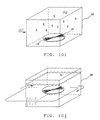
- Fig. 10 is a detailed visual step by step process for making an optical disc master in accord with the teachings of this patent.
- Fig 10a illustrates a perspective view of the formation of the transparent disc substrate 10.
- Polycarbonate pellets 70 are melted in an oven 72 and forced under pressure into a compression mold consisting of a tracking grooved side 74 and a smooth, planar side 76.
- Fig. 10b indicates the opening of the compression mold to release a transparent, polycarbonate disc substrate 1.
- a metalization process 80 is then performed to yield a reflective, thermo conductive layer 16 whereby a very thin layer of gold (Au) is deposited by conventional vapor deposition or sputtering means over the entire grooved side 12 of the disc.
- Au gold
- the photoreactive, nitrocellulose solution layer 18 is spin coated onto the grooved side 12 of disc 1 on top of the semitransparent metallic layer 16.
- FIG. 10f indicates an alternate embodiment or step in lieu of maintaining a clean room environment.
- a disc cover 82 is applied to the active side 18 of disc 1 and removably sealed thereto by a rubber or plastic grommet 84.
- the sealed and protected disc is then placed in a protective carrying tray 86.
- Fig. 10g illustrates the laser recording process wherein data pits are recorded by a laser modulating an focusing means 88 in the active layer 18 sealed and enclosed in disc cover 82 while both disc an cover spin about a spindle 90.
- FIG. 10h illustrates the novel improvement delineated in this invention whereby the disc 1 with recorded and active side face up on a conveyer belt 92 moving from left to right under and through an ultra violet light 94 which irradiates the active surface 18 and thereby eliminates any residual berm build up.
- Fig. 10l concludes the disc mastering process by vapor deposition process 96 of an electrically conductive silver (Ag) layer. From this optical disc (OD) master an OD stamper is formed in Fig. 10 by passing the disc master through a Galvanic bath/chamber to create a family series by building a nickel layer through an electroforming process 98 to make a "father” having bumps instead of the disc master "mother” with pits.
- OD optical disc
Landscapes
- Engineering & Computer Science (AREA)
- Manufacturing & Machinery (AREA)
- Optical Recording Or Reproduction (AREA)
- Optical Record Carriers And Manufacture Thereof (AREA)
- Manufacturing Optical Record Carriers (AREA)
Abstract
Description
Claims (9)
- A process for making an optical disc master from which an optical disc stamper can be made, comprising the steps of:forming a planar optical disc substrate (10; 40) having at least one surface for recording data;applying a partially reflective lamina (16; 46) to said recording surface, said reflective lamina (16; 46) having a thickness of less than about 50 Å, said partially reflective lamina (16; 46) being constructed from an opaque substance and applied in such an extremely thin manner that said partially reflective lamina (16; 46) is substantially transparent;applying an optically active lamina (18; 48) to said partially reflective lamina (16; 46);writing data to said optically active lamina (18; 48) by focusing a laser (22) to form a series of pits (24) in said optically active lamina (18; 48);heating, softening, and reflowing said optically active lamina (18; 48) by illuminating said active lamina (18; 48) with ultra violet radiation from at least one portion of the electromagnetic spectrum and thereby substantially eliminating any raised, berm areas typically around said pits (24; 54); andapplying a conductive lamina to said reflowed active lamina (18; 48) to complete an optical disc master.
- The process as defined by claim 1, wherein said step of writing data further consists of focusing a data modulated laser (22) in an area defined by said partially reflective lamina (16; 46) in said optically active lamina (18; 48).
- The process as defined by claim 2, wherein said recording surface has an optical tracking path (12) disposed thereon.
- The process as defined by claim 3, wherein the step of writing data consists of focusing said laser (22) on said optical tracking path (12) to form said pits (24).
- The process as defined by claim 4, wherein said substance used to create said partially reflective lamina (16) is a mineral.
- The process as defined by claim 5, wherein said substance used to create said partially reflective lamina (16) is a metal.
- The process as defined by claim 1, wherein said disc substrate (10; 40) is a polymer.
- The process as defined by claim 2, wherein said laser (22) means is disposed to focus through said disc substrate (10) to form pits (24) in said optically active lamina (18).
- An optical disc mastering process that utilizes the process of:wherein an additional step (dd) between steps d and e above is applied as follows:a- forming a transparent disc substrate (10);b- applying a lamina (16) of semi-transparent, semi-absorptive, and semi-reflective substance to said disc substrate(10);c- applying a lamina (18) of an optically active substance to said transparent, absorptive, reflective lamina (16);d- recording data by modulated laser (22) means passing through said transparent substrate (10) and through said transparent, absorptive, reflective lamina (16) to said active lamina (18); ande- applying a conductive lamina to said recorded, active lamina (18) to complete a disc master.dd- illuminating, radiating, softening, and reflowing said recorded, active lamina (18) to flatten and eliminate berm buildup prior to application of a conductive lamina.
Applications Claiming Priority (3)
| Application Number | Priority Date | Filing Date | Title |
|---|---|---|---|
| US08/648,532 US5741627A (en) | 1996-05-15 | 1996-05-15 | Optical recording medium and method for eliminating berm buildup |
| US648532 | 1996-05-15 | ||
| PCT/US1996/011618 WO1997043112A1 (en) | 1996-05-15 | 1996-07-11 | Optical recording medium and method for eliminating berm buildup |
Publications (3)
| Publication Number | Publication Date |
|---|---|
| EP0912324A1 EP0912324A1 (en) | 1999-05-06 |
| EP0912324A4 EP0912324A4 (en) | 2001-01-10 |
| EP0912324B1 true EP0912324B1 (en) | 2003-02-12 |
Family
ID=24601169
Family Applications (1)
| Application Number | Title | Priority Date | Filing Date |
|---|---|---|---|
| EP96924464A Expired - Lifetime EP0912324B1 (en) | 1996-05-15 | 1996-07-11 | Process for making an optical disc master |
Country Status (6)
| Country | Link |
|---|---|
| US (1) | US5741627A (en) |
| EP (1) | EP0912324B1 (en) |
| AT (1) | ATE232459T1 (en) |
| AU (1) | AU6490596A (en) |
| DE (1) | DE69626225D1 (en) |
| WO (1) | WO1997043112A1 (en) |
Families Citing this family (14)
| Publication number | Priority date | Publication date | Assignee | Title |
|---|---|---|---|---|
| US6022604A (en) * | 1998-01-16 | 2000-02-08 | Odme | Optical disk mastering system |
| US6814897B2 (en) | 1998-03-27 | 2004-11-09 | Discovision Associates | Method for manufacturing a molding tool used for substrate molding |
| US6207247B1 (en) * | 1998-03-27 | 2001-03-27 | Nikon Corporation | Method for manufacturing a molding tool used for sustrate molding |
| US6372175B1 (en) * | 1999-09-17 | 2002-04-16 | General Electric Company | Resin pellets for injection molding |
| US7016295B2 (en) * | 2000-04-26 | 2006-03-21 | Optical Disc Corporation | Hybrid discs displaying certain dimensional values |
| US6570840B1 (en) | 2000-04-26 | 2003-05-27 | Optical Disc Corporation | Figure of merit in optical recording structures |
| JP2002109875A (en) * | 2000-09-29 | 2002-04-12 | Nec Corp | Shadow ram cell using ferroelectric capacitor, and nonvolatile memory device and its control method |
| CN1582472B (en) * | 2001-10-31 | 2012-07-11 | 光盘公司 | Improved figure of merit in optical recording structure |
| AU2003266613A1 (en) * | 2002-10-10 | 2004-05-04 | Sony Corporation | Method of producing optical disk-use original and method of producing optical disk |
| EP1471510A1 (en) * | 2003-04-26 | 2004-10-27 | Optical Disc Corporation | Optical recording structures |
| WO2006072859A2 (en) * | 2005-01-06 | 2006-07-13 | Koninklijke Philips Electronics N.V. | Mastering based on heat-induced shrinkage of organic dyes |
| ATE472798T1 (en) | 2006-05-05 | 2010-07-15 | Moser Baer India Ltd | METHOD FOR PRINTING ON A PLATE |
| JP5098633B2 (en) * | 2007-12-27 | 2012-12-12 | ソニー株式会社 | Disc master, disc master manufacturing method, stamper, disc substrate, optical disc, optical disc manufacturing method |
| CN103594624B (en) * | 2013-11-07 | 2015-12-09 | 电子科技大学 | A kind of organic field effect tube and preparation method thereof |
Family Cites Families (12)
| Publication number | Priority date | Publication date | Assignee | Title |
|---|---|---|---|---|
| JPH0114038B2 (en) * | 1977-12-19 | 1989-03-09 | Eastman Kodak Co | |
| US4270130A (en) * | 1979-01-08 | 1981-05-26 | Eastman Kodak Company | Thermal deformation record device with bleachable dye |
| US4308337A (en) * | 1980-03-10 | 1981-12-29 | Rca Corporation | Uniform light exposure of positive photoresist for replicating spiral groove in plastic substrate |
| US4306013A (en) * | 1980-03-10 | 1981-12-15 | Rca Corporation | Asymmetrical radiation exposure of spin coated photoresist to obtain uniform thickness coating used to replicate spiral grooves in plastic substrate |
| US4613966A (en) * | 1983-06-30 | 1986-09-23 | International Business Machines Corporation | Sealed encapsulation for floppy disk using centrifugal force to flatten disk |
| US4646103A (en) * | 1985-03-20 | 1987-02-24 | Hitachi, Ltd. | Optical recording method |
| JPS63153743A (en) * | 1986-07-10 | 1988-06-27 | Hitachi Maxell Ltd | Optical information recording medium and its production |
| JPH0246538A (en) * | 1988-08-05 | 1990-02-15 | Sharp Corp | Optical memory element |
| US5099469A (en) * | 1990-02-20 | 1992-03-24 | Del Mar Avionics | Process for manufacturing an optical disc master |
| JP2852792B2 (en) * | 1990-07-05 | 1999-02-03 | 三菱電機株式会社 | Optical disk drive |
| NL9002594A (en) * | 1990-11-28 | 1992-06-16 | Philips & Du Pont Optical | MASTER PLATE. |
| EP0611473B1 (en) * | 1991-10-03 | 1997-05-02 | Del Mar Avionics | Optical disc master |
-
1996
- 1996-05-15 US US08/648,532 patent/US5741627A/en not_active Expired - Fee Related
- 1996-07-11 EP EP96924464A patent/EP0912324B1/en not_active Expired - Lifetime
- 1996-07-11 AU AU64905/96A patent/AU6490596A/en not_active Abandoned
- 1996-07-11 DE DE69626225T patent/DE69626225D1/en not_active Expired - Lifetime
- 1996-07-11 WO PCT/US1996/011618 patent/WO1997043112A1/en not_active Ceased
- 1996-07-11 AT AT96924464T patent/ATE232459T1/en not_active IP Right Cessation
Also Published As
| Publication number | Publication date |
|---|---|
| DE69626225D1 (en) | 2003-03-20 |
| AU6490596A (en) | 1997-12-05 |
| ATE232459T1 (en) | 2003-02-15 |
| EP0912324A1 (en) | 1999-05-06 |
| WO1997043112A1 (en) | 1997-11-20 |
| EP0912324A4 (en) | 2001-01-10 |
| US5741627A (en) | 1998-04-21 |
Similar Documents
| Publication | Publication Date | Title |
|---|---|---|
| US6022604A (en) | Optical disk mastering system | |
| US5741627A (en) | Optical recording medium and method for eliminating berm buildup | |
| EP0447711B1 (en) | Process for manufacturing an optical disk master | |
| JP2564638B2 (en) | Compact disc manufacturing method | |
| US5283159A (en) | Optical recording medium and method for improved pit geometry and increased laser tracking | |
| WO1998048417A1 (en) | Optical recording medium and its substrate | |
| JP4511787B2 (en) | Multilayer optical disc and method for producing multilayer optical disc | |
| US6665260B2 (en) | Optical recording medium including protruding winding parts used as prepits | |
| JPH10275365A (en) | Information storage medium and information reproducing apparatus | |
| CN100395835C (en) | Information storage medium, stamper, disk device and management information playback method | |
| JP2006085791A (en) | Optical information recording medium | |
| JP4064871B2 (en) | Optical disc and optical disc manufacturing method | |
| TW591639B (en) | Optical recording medium and optical recording method | |
| JP2001202659A (en) | Recording type optical disk and method of manufacturing the same | |
| JP4288818B2 (en) | Optical recording medium | |
| JP2002184032A (en) | Optical disk and method of manufacturing the same | |
| JP2006172688A (en) | Optical information recording medium | |
| JP2517470B2 (en) | Method and device for manufacturing optical disc master | |
| HK1033197A (en) | Optical disc mastering system | |
| JPWO2003023775A1 (en) | Method of manufacturing master for recording medium and method of manufacturing stamper | |
| JPH04307441A (en) | Information recording medium | |
| JP2005310320A (en) | Optical information recording medium | |
| JPH02266978A (en) | Optical information recording medium | |
| JP2001216655A (en) | Optical recording medium, master for producing optical recording medium, and recording / reproducing method | |
| JP2002175647A (en) | Device for manufacturing substrate for information recording carrier, method of manufacturing substrate information recording carrier and method of manufacturing information recording carrier |
Legal Events
| Date | Code | Title | Description |
|---|---|---|---|
| PUAI | Public reference made under article 153(3) epc to a published international application that has entered the european phase |
Free format text: ORIGINAL CODE: 0009012 |
|
| 17P | Request for examination filed |
Effective date: 19981215 |
|
| AK | Designated contracting states |
Kind code of ref document: A1 Designated state(s): AT BE CH DE DK ES FI FR GB GR IE IT LI LU MC NL PT SE |
|
| A4 | Supplementary search report drawn up and despatched |
Effective date: 20001129 |
|
| AK | Designated contracting states |
Kind code of ref document: A4 Designated state(s): AT BE CH DE DK ES FI FR GB GR IE IT LI LU MC NL PT SE |
|
| RIC1 | Information provided on ipc code assigned before grant |
Free format text: 7B 29D 17/00 A, 7G 03C 1/73 B, 7G 03C 5/16 B, 7G 03C 5/56 B, 7G 11B 7/26 B |
|
| RAP1 | Party data changed (applicant data changed or rights of an application transferred) |
Owner name: ODME INTERNATIONAL B.V. |
|
| RAP1 | Party data changed (applicant data changed or rights of an application transferred) |
Owner name: OTB GROUP B.V. |
|
| 17Q | First examination report despatched |
Effective date: 20011214 |
|
| GRAG | Despatch of communication of intention to grant |
Free format text: ORIGINAL CODE: EPIDOS AGRA |
|
| RTI1 | Title (correction) |
Free format text: PROCESS FOR MAKING AN OPTICAL DISC MASTER |
|
| RTI1 | Title (correction) |
Free format text: PROCESS FOR MAKING AN OPTICAL DISC MASTER |
|
| GRAG | Despatch of communication of intention to grant |
Free format text: ORIGINAL CODE: EPIDOS AGRA |
|
| GRAG | Despatch of communication of intention to grant |
Free format text: ORIGINAL CODE: EPIDOS AGRA |
|
| GRAH | Despatch of communication of intention to grant a patent |
Free format text: ORIGINAL CODE: EPIDOS IGRA |
|
| GRAH | Despatch of communication of intention to grant a patent |
Free format text: ORIGINAL CODE: EPIDOS IGRA |
|
| GRAA | (expected) grant |
Free format text: ORIGINAL CODE: 0009210 |
|
| AK | Designated contracting states |
Designated state(s): AT BE CH DE DK ES FI FR GB GR IE IT LI LU MC NL PT SE |
|
| PG25 | Lapsed in a contracting state [announced via postgrant information from national office to epo] |
Ref country code: NL Free format text: LAPSE BECAUSE OF FAILURE TO SUBMIT A TRANSLATION OF THE DESCRIPTION OR TO PAY THE FEE WITHIN THE PRESCRIBED TIME-LIMIT Effective date: 20030212 Ref country code: LI Free format text: LAPSE BECAUSE OF FAILURE TO SUBMIT A TRANSLATION OF THE DESCRIPTION OR TO PAY THE FEE WITHIN THE PRESCRIBED TIME-LIMIT Effective date: 20030212 Ref country code: IT Free format text: LAPSE BECAUSE OF FAILURE TO SUBMIT A TRANSLATION OF THE DESCRIPTION OR TO PAY THE FEE WITHIN THE PRESCRIBED TIME-LIMIT;WARNING: LAPSES OF ITALIAN PATENTS WITH EFFECTIVE DATE BEFORE 2007 MAY HAVE OCCURRED AT ANY TIME BEFORE 2007. THE CORRECT EFFECTIVE DATE MAY BE DIFFERENT FROM THE ONE RECORDED. Effective date: 20030212 Ref country code: GR Free format text: LAPSE BECAUSE OF FAILURE TO SUBMIT A TRANSLATION OF THE DESCRIPTION OR TO PAY THE FEE WITHIN THE PRESCRIBED TIME-LIMIT Effective date: 20030212 Ref country code: FR Free format text: LAPSE BECAUSE OF FAILURE TO SUBMIT A TRANSLATION OF THE DESCRIPTION OR TO PAY THE FEE WITHIN THE PRESCRIBED TIME-LIMIT Effective date: 20030212 Ref country code: FI Free format text: LAPSE BECAUSE OF FAILURE TO SUBMIT A TRANSLATION OF THE DESCRIPTION OR TO PAY THE FEE WITHIN THE PRESCRIBED TIME-LIMIT Effective date: 20030212 Ref country code: CH Free format text: LAPSE BECAUSE OF FAILURE TO SUBMIT A TRANSLATION OF THE DESCRIPTION OR TO PAY THE FEE WITHIN THE PRESCRIBED TIME-LIMIT Effective date: 20030212 Ref country code: BE Free format text: LAPSE BECAUSE OF FAILURE TO SUBMIT A TRANSLATION OF THE DESCRIPTION OR TO PAY THE FEE WITHIN THE PRESCRIBED TIME-LIMIT Effective date: 20030212 Ref country code: AT Free format text: LAPSE BECAUSE OF FAILURE TO SUBMIT A TRANSLATION OF THE DESCRIPTION OR TO PAY THE FEE WITHIN THE PRESCRIBED TIME-LIMIT Effective date: 20030212 |
|
| REG | Reference to a national code |
Ref country code: GB Ref legal event code: FG4D |
|
| REG | Reference to a national code |
Ref country code: CH Ref legal event code: EP |
|
| REF | Corresponds to: |
Ref document number: 69626225 Country of ref document: DE Date of ref document: 20030320 Kind code of ref document: P |
|
| PG25 | Lapsed in a contracting state [announced via postgrant information from national office to epo] |
Ref country code: SE Free format text: LAPSE BECAUSE OF FAILURE TO SUBMIT A TRANSLATION OF THE DESCRIPTION OR TO PAY THE FEE WITHIN THE PRESCRIBED TIME-LIMIT Effective date: 20030512 Ref country code: PT Free format text: LAPSE BECAUSE OF FAILURE TO SUBMIT A TRANSLATION OF THE DESCRIPTION OR TO PAY THE FEE WITHIN THE PRESCRIBED TIME-LIMIT Effective date: 20030512 Ref country code: DK Free format text: LAPSE BECAUSE OF FAILURE TO SUBMIT A TRANSLATION OF THE DESCRIPTION OR TO PAY THE FEE WITHIN THE PRESCRIBED TIME-LIMIT Effective date: 20030512 |
|
| PG25 | Lapsed in a contracting state [announced via postgrant information from national office to epo] |
Ref country code: DE Free format text: LAPSE BECAUSE OF FAILURE TO SUBMIT A TRANSLATION OF THE DESCRIPTION OR TO PAY THE FEE WITHIN THE PRESCRIBED TIME-LIMIT Effective date: 20030513 |
|
| NLV1 | Nl: lapsed or annulled due to failure to fulfill the requirements of art. 29p and 29m of the patents act | ||
| REG | Reference to a national code |
Ref country code: IE Ref legal event code: FG4D |
|
| PG25 | Lapsed in a contracting state [announced via postgrant information from national office to epo] |
Ref country code: LU Free format text: LAPSE BECAUSE OF NON-PAYMENT OF DUE FEES Effective date: 20030711 Ref country code: IE Free format text: LAPSE BECAUSE OF NON-PAYMENT OF DUE FEES Effective date: 20030711 Ref country code: GB Free format text: LAPSE BECAUSE OF NON-PAYMENT OF DUE FEES Effective date: 20030711 |
|
| PG25 | Lapsed in a contracting state [announced via postgrant information from national office to epo] |
Ref country code: MC Free format text: LAPSE BECAUSE OF NON-PAYMENT OF DUE FEES Effective date: 20030731 |
|
| PG25 | Lapsed in a contracting state [announced via postgrant information from national office to epo] |
Ref country code: ES Free format text: LAPSE BECAUSE OF FAILURE TO SUBMIT A TRANSLATION OF THE DESCRIPTION OR TO PAY THE FEE WITHIN THE PRESCRIBED TIME-LIMIT Effective date: 20030828 |
|
| REG | Reference to a national code |
Ref country code: CH Ref legal event code: PL |
|
| PLBE | No opposition filed within time limit |
Free format text: ORIGINAL CODE: 0009261 |
|
| STAA | Information on the status of an ep patent application or granted ep patent |
Free format text: STATUS: NO OPPOSITION FILED WITHIN TIME LIMIT |
|
| EN | Fr: translation not filed | ||
| 26N | No opposition filed |
Effective date: 20031113 |
|
| GBPC | Gb: european patent ceased through non-payment of renewal fee |
Effective date: 20030711 |
|
| REG | Reference to a national code |
Ref country code: IE Ref legal event code: MM4A |