EP0912009A2 - Date rate conversion using repetition codes - Google Patents
Date rate conversion using repetition codes Download PDFInfo
- Publication number
- EP0912009A2 EP0912009A2 EP98308693A EP98308693A EP0912009A2 EP 0912009 A2 EP0912009 A2 EP 0912009A2 EP 98308693 A EP98308693 A EP 98308693A EP 98308693 A EP98308693 A EP 98308693A EP 0912009 A2 EP0912009 A2 EP 0912009A2
- Authority
- EP
- European Patent Office
- Prior art keywords
- symbols
- data rate
- block
- frame
- signal
- Prior art date
- Legal status (The legal status is an assumption and is not a legal conclusion. Google has not performed a legal analysis and makes no representation as to the accuracy of the status listed.)
- Withdrawn
Links
Images


Classifications
-
- H—ELECTRICITY
- H04—ELECTRIC COMMUNICATION TECHNIQUE
- H04L—TRANSMISSION OF DIGITAL INFORMATION, e.g. TELEGRAPHIC COMMUNICATION
- H04L1/00—Arrangements for detecting or preventing errors in the information received
- H04L1/0001—Systems modifying transmission characteristics according to link quality, e.g. power backoff
- H04L1/0002—Systems modifying transmission characteristics according to link quality, e.g. power backoff by adapting the transmission rate
-
- H—ELECTRICITY
- H04—ELECTRIC COMMUNICATION TECHNIQUE
- H04L—TRANSMISSION OF DIGITAL INFORMATION, e.g. TELEGRAPHIC COMMUNICATION
- H04L1/00—Arrangements for detecting or preventing errors in the information received
- H04L1/004—Arrangements for detecting or preventing errors in the information received by using forward error control
- H04L1/0056—Systems characterized by the type of code used
- H04L1/0067—Rate matching
- H04L1/0068—Rate matching by puncturing
-
- H—ELECTRICITY
- H04—ELECTRIC COMMUNICATION TECHNIQUE
- H04J—MULTIPLEX COMMUNICATION
- H04J3/00—Time-division multiplex systems
- H04J3/22—Time-division multiplex systems in which the sources have different rates or codes
-
- H—ELECTRICITY
- H04—ELECTRIC COMMUNICATION TECHNIQUE
- H04L—TRANSMISSION OF DIGITAL INFORMATION, e.g. TELEGRAPHIC COMMUNICATION
- H04L1/00—Arrangements for detecting or preventing errors in the information received
- H04L1/0001—Systems modifying transmission characteristics according to link quality, e.g. power backoff
- H04L1/0009—Systems modifying transmission characteristics according to link quality, e.g. power backoff by adapting the channel coding
- H04L1/0013—Rate matching, e.g. puncturing or repetition of code symbols
-
- H—ELECTRICITY
- H04—ELECTRIC COMMUNICATION TECHNIQUE
- H04L—TRANSMISSION OF DIGITAL INFORMATION, e.g. TELEGRAPHIC COMMUNICATION
- H04L1/00—Arrangements for detecting or preventing errors in the information received
- H04L1/004—Arrangements for detecting or preventing errors in the information received by using forward error control
- H04L1/0056—Systems characterized by the type of code used
- H04L1/0071—Use of interleaving
-
- H—ELECTRICITY
- H04—ELECTRIC COMMUNICATION TECHNIQUE
- H04L—TRANSMISSION OF DIGITAL INFORMATION, e.g. TELEGRAPHIC COMMUNICATION
- H04L1/00—Arrangements for detecting or preventing errors in the information received
- H04L1/08—Arrangements for detecting or preventing errors in the information received by repeating transmission, e.g. Verdan system
Definitions
- the present invention relates to data rate conversion and, in particular, relates to a method and device for converting a digital signal having a first data rate to a digital signal having a second, higher or lower, data rate.
- One embodiment of the invention relates to a method for converting a signal data rate from a lower data rate to a higher data rate in a digital data transmission system, wherein a signal is transmitted by using frames of a given length, which length corresponds to the higher data rate, in which method the signal is grouped to a first block the length of which corresponds to the lower data rate, and wherein symbols to be transmitted are subjected to repetition coding.
- Another embodiment of the invention relates to a method for converting a signal data rate from a higher data rate to a lower data rate in a digital data transmission system, wherein a signal is transmitted by using frames of a given length, which length corresponds to the lower data rate, in which method the signal is grouped to a first block the length of which corresponds to the higher data rate, and wherein symbols to be transmitted are subjected to removal coding.
- wireless data transmission systems have been used to transmit only speech.
- the increasing number of different services to be transmitted means especially in wireless systems that a system must be able to transmit signals with different capacities over the radio path, for example to transmit speech at the data rate of 8 kbps and data at the rate of 64 kbps.
- a typical example is a video connection where the image requires a high data rate and a high quality level, but the voice can be transmitted at a lower data rate and with a lower quality level. Therefore, a data transmission system should be able to operate effectively in an environment where transmissions of several different data rates, quality levels and service types are forwarded.
- a data rate can be either increased or decreased, as required.
- the best known and the simplest method of increasing the data rate is repetition coding, wherein user data symbols are repeated as many times as there are free symbol positions in the frame.
- the data rate is decreased in the simplest manner by removing user data symbols until the remaining symbols fit in the available frame.
- the problem in the prior art arrangement is how to select the symbols to be repeated or removed so that they are distributed evenly among the symbols to be transmitted. It is an object of the invention to address this problem.
- a method for converting a signal data rate from a lower data rate to a higher data rate in a digital data transmission system wherein a signal is transmitted by using frames of a given length, which length corresponds to the higher data rate, in which method the signal is grouped to a first block the length of which corresponds to the lower data rate, and wherein symbols to be transmitted are subjected to repetition coding, the method comprising the steps of:
- a method for converting a signal data rate from a higher data rate to a lower data rate in a digital data transmission system wherein a signal is transmitted by using frames of a given length, which length corresponds to the lower data rate, in which method the signal is grouped to a first block the length of which corresponds to the higher data rate, and wherein symbols to be transmitted are subjected to removal coding, the method comprising the steps of:
- the calculation of the number of symbols missing from the frame in step A2 may be carried out by subtracting the frame length from the number of symbols in the first block.
- a transmitter in a digital data transmission system comprising means (200 - 204, 456 - 460) for generating a signal (206 - 210, 400 - 404) having a first data rate, and means (214, 422) for forming the signal in frames of a given length that corresponds to a second data rate, and means (214, 422) for grouping the signal (206 - 210, 400 - 404) in a first block the length of which corresponds to the first data rate, the transmitter comprising:
- a processor, a transmitter or a receiver may be arranged to carry out the method of data rate conversion and the step of determining whether symbols should be added or removed.
- the processor may be used in a transmitter or a receiver.
- a processor may be arranged to carry out data rate conversion. Such a processor may be used in a transmitter or a receiver.
- the preferred embodiments of the invention are disclosed in the dependent claims.
- the method and the transmitter according to the invention provide several advantages.
- the symbols to be repeated or removed can be selected as evenly as possible from among the symbols to be transmitted. In this manner the quality of the coding is the best possible.
- the method according to the invention enables flexible rate adaptation between data rates of different types.
- the method according to the invention enables unambiguous repetition or removal, so that it is possible to deduce the repeated symbols at the receiving end if the algorithm is known.
- Figure 1 illustrates a digital data transmission system where the arrangement according to the invention can be applied.
- This system is a part of a cellular radio system comprising a base station 100 that communicates via a bidirectional connection 102 to 106 with subscriber terminals 108 to 112.
- the digital data transmission system used as an example is a cellular radio system, and the invention will be described in the following when it is applied in a cellular radio system but without restricting the invention thereto, as it is evident for a person skilled in the art.
- the invention is also applicable in other systems.
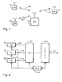
- FIG. 2 is a block diagram illustrating a possible structure of a transmitter implementing the arrangement according to the invention.
- the transmitter comprises a number of data sources 200 to 204, which may be provided for example for speech transmission or different data services.
- the information is subjected to channel coding.
- Signals 206 to 210 from the data sources are in the form of frames and their data rates differ from one another.
- the transmitter further comprises a switch or a multiplexer 212, which selects or combines the signal from the active data source(s) to coding means 214.
- Control means 216 control the operation of the switch or the multiplexer 212 and the other parts of the transmitter.
- the control and coding means 214, 216 are implemented most preferably with a processor by means of software.
- a signal 218 supplied from the coding means 214 is in the form of a frame.
- the data rates of the signals from the data sources are adapted to the frame by using either repetition or removal coding by means of the arrangement according to the invention.
- the transmitter of Figure 2 only comprises components that are essential for describing the invention.
- An actual transmitter also comprises other parts, such as filters and amplifiers, that are evident for a person skilled in the art, but they are not described herein for the sake of clarity.
- Figures 3a to 3d illustrate the arrangement according to the invention by means of different frame alternatives.
- FIG. 3a shows a data frame 300 of a channel, and a frame 302 of a data source.
- the channel data rate N T is higher than the information data rate N C .
- Figure 3b shows the data frame 300 of the channel and the frame 304 of the data source. In the example of Figure 3b, the channel data rate N T is lower than the information data rate N C .
- a first block S 0 ⁇ d 1 , d 2 , ..., d ns ⁇ is formed of the N c symbols to be transmitted.
- n s is the number of symbols in the block S 0
- n s N c .
- the purpose is to convert the lower data rate into a higher data rate by repeating N T - N C symbols from the block S 0 , such that after the repetition the block size is N T symbols.
- the repetitions are preferably distributed as evenly as possible in the frame to be transmitted.
- the number of symbols y missing from the frame is calculated first by subtracting from the frame length N T the number of symbols N C in the first block. If the number of missing symbols is one, the first symbol in the block is repeated and the procedure is over. Otherwise term i is defined, such that wherein n S is the number of symbols in the block S 0 . In other words, i is determined as the nearest bigger or an equal integer when the number of symbols in the first block is divided by the number of symbols missing from the frame.
- the first step of the repetition coding is carried out by repeating every ith symbol in the block S 0 .
- the number n R of the repeated symbols is obtained by determining the nearest smaller or an equal integer when the number of symbols in the block is divided by i , i.e.
- the block S 0 is updated next by removing therefrom the symbols that have been repeated. After this, the number of symbols missing from the frame to be transmitted is updated by subtracting from it the number of the symbols that have been repeated, and the above-described procedure is repeated until all the symbol positions in the frame to be transmitted are in use.
- a first block S 0 ⁇ d 1 , d 2 , ..., d ns ⁇ is formed of the N C symbols to be transmitted.
- n s is the number of symbols in the block S 0
- n s N C .
- the purpose is to convert the higher data rate into a lower data rate by removing N C - N T symbols from the block S 0 , such that after the removals the block size is N T symbols.
- the removals are preferably distributed as evenly as possible in the frame to be transmitted.
- the number of symbols y that do not fit in the frame is calculated by subtracting the frame length N T from the number of symbols N C in the first block. If the number of symbols is one, the last symbol in the block is removed and the procedure is over. Otherwise term i is defined, such that wherein n S is the number of symbols in the block S 0 . In other words, i is determined as the nearest bigger or an equal integer when the number of symbols in the first block is divided by the number of symbols that do not fit in the frame.
- the first step of the removal coding is carried out by removing every ith symbol in the block S 0 .
- the number n R of the removed symbols is obtained by determining the nearest smaller or an equal integer when the number of symbols in the block is divided by i , i.e.
- the block S 0 is updated next to consist of the symbols that have not been removed. After this, the number of symbols that do not fit in the frame to be transmitted is updated by subtracting therefrom the number of the symbols that have been removed, and the above-described procedure is repeated until the symbols to be transmitted fit in the frame to be transmitted.
- Figure 3c shows a data frame 300 of the channel and a frame 306 of the data source.
- the channel data rate N T is higher than the information data rate N C , such that N T - N C N C > 1, i.e. the size of the frame to be transmitted is more than double the number of symbols in the information to be transmitted.
- each symbol to be transmitted is repeated a sufficient number of times and the first block S 0 is formed of this symbol group. After this, the procedure is as described above.
- the channel data rate N T is lower than the information data rate N C , such that N C - N T N C ⁇ A, wherein A is a predetermined positive constant from (0,1).
- A may be for example 0.2.
- Figure 3d shows a frame 310 of a data source and two frames 300, 308 of different lengths that are used in the system and that contain N T and N T1 symbols, such that N T ⁇ N T1 .
- the adaptation is carried out by selecting for signal transmission the larger frame, which is subjected to repetition coding.
- the symbols in the frame 310 of the data source are not transmitted through puncturing in the shorter frame 300, but the larger frame 308 is selected for use and the repetition coding is executed with the method described above. In this manner it is possible to avoid a large number of removals that might deteriorate the signal quality.
- Another alternative in the situation of Figure 3d is to divide the symbols in the frame 310 of the data source into two smaller frames 300 where the repetition coding according to the invention is carried out.
- FIG. 4 is a block diagram illustrating a possible structure of a transmitter implementing the arrangement according to the invention.
- the transmitter used as an example in the figure utilizes the CDMA multiple access method, but the idea of the invention can naturally also be applied in other types of transmitters.
- the transmitter according to the invention therefore comprises a number of data sources 456 to 460, which have output signals 400 to 404 with different quality level requirements and different data rates, and which may produce signals that are to be transmitted simultaneously.
- Possible data transmitters typically include a speech coder, a telefax terminal, a video coder or some other source producing digital information.
- the transmitter according to the invention further comprises first coders 406, 408 for subjecting at least some of the signals to be transmitted to external coding, such that due to the coding the quality level requirement of the signals coded in this manner equals the lowest quality level requirement of the active data sources. Therefore, all the signals to be transmitted are provided with the same quality level requirement.
- the coding to be used can be carried out in known manners and it is preferable to use the Reed-Solomon coding method.
- the transmitter may also comprise first interleavers 410, 412 for interleaving the coded signals, which means that the positions of the symbols in the signal are changed according to a known algorithm.
- the signals 400, 416, 418 that are obtained from all the data sources and that have thus a common quality level requirement are supplied to a multiplexer 414, wherein the signals are combined on a time domain into frames of equal length that contain bits in numbers that may vary from frame to frame, depending on the signals at the input of the multiplexer.
- the output of the multiplexer 414 is functionally connected to a second coder 420, where the signal is subjected to internal coding.
- This coder 420 may be any desired coder.
- the preferred embodiment utilizes a convolutional coder with which it is possible to lower the common quality level requirement.
- the signal 450 coded in this manner is supplied to means 422, where the frames to be transmitted are subjected to equalization of the number of symbols, such that the length of the symbols to be transmitted in each frame equals a multiple of a known time span that is substantially shorter than the symbol length. In connection with the CDMA method, this may be a multiple of the bit length or chip length of the spreading code.
- the number of the symbols can be equalized by either repeating or removing symbols in the above-described manner according to the invention.
- the means 422 can be preferably implemented by means of software through signal processing with a signal processor.
- the symbols of the signal are grouped into a first block the length of which corresponds to a desired equalized data rate.
- the difference between the symbols in the frame and the desired number of symbols is calculated by subtracting the desired number from the number of symbols in the first block.
- the difference is equalized in the means 422 by removing or repeating every ith symbol in the first block, i being determined as the nearest bigger or an equal integer when the number of symbols in the first block is divided by the difference calculated.
- the means 422 form the first block so that it consists of the symbols that have not been repeated or have not been removed, and they repeat the above-described procedure until the desired number of symbols is achieved.
- the transmitter it is also possible to form frames of different lengths, and when the higher data rate exceeds the lower data rate by a certain threshold, a larger frame is selected for signal transmission, and repetition coding is carried out.
- the transmitter according to the invention further comprises a multiplexer 434, which combines data about the frame structure of each frame, e.g. about the bit rate, to the signal frames that are to be transmitted and that contain an equal number of symbols.
- the data 426 concerning the frame structure is supplied first to a coder 432, where the desired coding is executed to protect the information against transmission errors, and the coded signal is supplied to the multiplexer 434.
- This data may comprise, for example, a description of the frame structure of the frame in question or the next frame to be transmitted.
- the signal 452 combined in this manner is supplied further to an interleaver 436.
- the transmitter may comprise a multiplexer 438, where the interleaved signal is supplemented with additional information, such as power control data 428 or reference symbols 430 for coherent reception.
- additional information such as power control data 428 or reference symbols 430 for coherent reception.
- the transmitter is a CDMA transmitter
- the combined signal 440 is supplied to a multiplier 442, where the signal is multiplied by a spreading code characteristic of the connection, so that the signal spreads to the entire frequency band used.
- the signal multiplied in this manner is supplied further to radio-frequency parts, where the signal is converted into a radio frequency and amplified for transmission by an antenna 446.
- the transmitter comprises control means 454, which control the operation of the above-described parts and which may be implemented for example by means of a microprocessor, separate logic circuits or the like.
- the control means 454 also provide control to the radio-frequency parts 444 concerning the transmit power of each frame to be transmitted, and this power may depend on the number of symbols in the frame after the multiplexer 414.
- the transmitter according to the invention naturally also comprises other components, such as filters and converters, as it is evident for a person skilled in the art, but for the sake of clarity they are not mentioned in Figure 4 and in the description related thereto.
Abstract
The invention relates to a method for converting a signal data rate and to a transmitter
in a digital data transmission system, the transmitter comprising a number of data
sources (200 - 204) that generate a signal (206 - 210) having a first data rate, and a
coder (214) for forming the signal into frames of a given length, which length
corresponds to a second data rate, and a coder (214) for grouping the signal (206 -
210) into a first block the length of which corresponds to the first data rate. In order to
convert the data rate flexibly, the transmitter comprises a coder (214), which
calculates the difference between the frame and the number of symbols in the first
block by subtracting the frame length from the number of symbols in the first block,
which equalizes the difference by removing or repeating every ith symbol in the first
block, i being determined as the nearest bigger or an equal integer when the number
of symbols in the first block is divided by the absolute value of the difference that was
calculated, which updates the number of the symbols that do not fit in the frame by
subtracting therefrom the number of the symbols that have been repeated, and which
forms the first block to consist of the symbols that have not been repeated or
removed.
Description
- The present invention relates to data rate conversion and, in particular, relates to a method and device for converting a digital signal having a first data rate to a digital signal having a second, higher or lower, data rate.
- One embodiment of the invention relates to a method for converting a signal data rate from a lower data rate to a higher data rate in a digital data transmission system, wherein a signal is transmitted by using frames of a given length, which length corresponds to the higher data rate, in which method the signal is grouped to a first block the length of which corresponds to the lower data rate, and wherein symbols to be transmitted are subjected to repetition coding.
- Another embodiment of the invention relates to a method for converting a signal data rate from a higher data rate to a lower data rate in a digital data transmission system, wherein a signal is transmitted by using frames of a given length, which length corresponds to the lower data rate, in which method the signal is grouped to a first block the length of which corresponds to the higher data rate, and wherein symbols to be transmitted are subjected to removal coding.
- The requirements set for data transmission systems continue to increase. This concerns especially wireless data transmission systems, such as cellular radio systems, which are required to provide more and more varied services, including different data and video services.
- Traditionally, wireless data transmission systems have been used to transmit only speech. The increasing number of different services to be transmitted means especially in wireless systems that a system must be able to transmit signals with different capacities over the radio path, for example to transmit speech at the data rate of 8 kbps and data at the rate of 64 kbps. It is also necessary to transmit signals with different quality levels, which typically require different data rates simultaneously. A typical example is a video connection where the image requires a high data rate and a high quality level, but the voice can be transmitted at a lower data rate and with a lower quality level. Therefore, a data transmission system should be able to operate effectively in an environment where transmissions of several different data rates, quality levels and service types are forwarded.
It is typical of digital data transmission systems that signals are transmitted in frames and that the size of a frame is predetermined. when different data rates are used, it is not always possible to select for all data rates a frame which is exactly of the correct size and which has space for the symbols to be transmitted, but it is necessary to change the data rate so that the information to be transmitted can be forwarded in the available frames. - A data rate can be either increased or decreased, as required. The best known and the simplest method of increasing the data rate is repetition coding, wherein user data symbols are repeated as many times as there are free symbol positions in the frame. Correspondingly, the data rate is decreased in the simplest manner by removing user data symbols until the remaining symbols fit in the available frame. The problem in the prior art arrangement is how to select the symbols to be repeated or removed so that they are distributed evenly among the symbols to be transmitted. It is an object of the invention to address this problem.
- According to one aspect of the present invention there is provided a method for converting a signal data rate from a lower data rate to a higher data rate in a digital data transmission system, wherein a signal is transmitted by using frames of a given length, which length corresponds to the higher data rate, in which method the signal is grouped to a first block the length of which corresponds to the lower data rate, and wherein symbols to be transmitted are subjected to repetition coding, the method comprising the steps of:
- A1) calculating the number of symbols missing from the frame, and if the number of the missing symbols is greater than one,
- B1) repeating every ith symbol of the first block, i being determined as the nearest bigger or an equal integer when the number of symbols in the first block is divided by the number of symbols missing from the frame,
- C1) updating the first block by removing therefrom the symbols that have been repeated,
- D1) updating the number of symbols missing from the frame by subtracting therefrom the number of the symbols that have been repeated, and if the number of the missing symbols is greater than one,
- E1) proceeding to step B1). The calculation of the number of symbols missing from the frame in step A1 may be carried out by subtracting from the frame length the number of symbols in the first block.
-
- According to another aspect of the present invention there is provided a method for converting a signal data rate from a higher data rate to a lower data rate in a digital data transmission system, wherein a signal is transmitted by using frames of a given length, which length corresponds to the lower data rate, in which method the signal is grouped to a first block the length of which corresponds to the higher data rate, and wherein symbols to be transmitted are subjected to removal coding, the method comprising the steps of:
- A2) calculating the number of symbols that do not fit in the frame, and if the calculated number of symbols is greater than one,
- B2) removing every ith symbol of the first block, i being determined as the nearest bigger or an equal integer when the number of symbols in the first block is divided by the number of symbols that do not fit in the frame,
- C2) forming the first block to consist of the symbols that have not been removed,
- D2) updating the number of symbols that do not fit in the frame by subtracting therefrom the number of the removed symbols, and if the updated number of symbols is greater than one,
- E2) proceeding to step B2).
-
- The calculation of the number of symbols missing from the frame in step A2 may be carried out by subtracting the frame length from the number of symbols in the first block.
- According to a further aspect of the present invention there is provided a transmitter in a digital data transmission system, comprising means (200 - 204, 456 - 460) for generating a signal (206 - 210, 400 - 404) having a first data rate, and means (214, 422) for forming the signal in frames of a given length that corresponds to a second data rate, and means (214, 422) for grouping the signal (206 - 210, 400 - 404) in a first block the length of which corresponds to the first data rate, the transmitter comprising:
- means (214, 422) for calculating the difference between the frame and the number of symbols in the first block,
- means (214, 422) for equalizing the difference by removing or repeating every ith symbol of the first block, i being determined as the nearest bigger or an equal integer when the number of symbols in the first block is divided by the absolute value of the difference that was calculated,
- means (214, 422) for updating the number of symbols that do not fit in the frame by subtracting therefrom the number of the symbols that have been repeated or have been removed, and
- means (214, 422) for forming the first block to consist of the symbols that have not been repeated or have not been removed.
-
- According to another aspect of the present invention there is provided a method for converting a digital signal comprising symbols and having a first data rate to a second data rate by either repeating symbols or by removing symbols, wherein the signal having the first data rate is grouped in a block having a length corresponding to the first data rate and the signal having the second data rate uses a frame having a length corresponding to the second data rate, comprising the steps of:
- a) determining whether symbols should be repeated or removed to effect said
conversion;
and, if symbols should be repeated then :- - b) calculating the number of symbols missing from the frame on conversion and if the calculated number is greater than one;
- c) repeating every ith symbol of the block, i being determined as the nearest bigger or an equal integer when the number of symbols in the block is divided by the number of symbols missing from the frame;
- d) updating the block by removing therefrom the symbols that have been repeated ; and
- e) updating the number of symbols missing from the frame and if the number of the
missing symbols is greater than one, proceeding to step c),
and, if symbols should be removed, then :- - f) calculating the number of symbols that would not fit in the frame on conversion, and if the calculated number is greater than one;
- g) removing every ith symbol of the block, i being determined as the nearest bigger or an equal integer when the number of symbols in the block is divided by the number of symbols which do not fit in the frame;
- h) updating the block by removing therefrom the symbols that have been removed; and
- i) updating the number of symbols that do not fit in the frame and if the number of the missing symbols is greater than one, proceeding to step g).
-
- A processor, a transmitter or a receiver may be arranged to carry out the method of data rate conversion and the step of determining whether symbols should be added or removed. The processor may be used in a transmitter or a receiver.
- According to another aspect of the present invention there is provided a method for converting a digital signal comprising symbols and having a first data rate to a second higher data rate by repeating symbols, wherein the signal having the first data rate is grouped in a block having a length corresponding to the first data rate and the signal having the second data rate uses a frame having a length corresponding to the second data rate, comprising the steps of:
- a) calculating the number of symbols missing from the frame on conversion and if the calculated number is greater than one then;
- b) repeating every ith symbol of the block, i being determined as the nearest bigger or an equal integer when the number of symbols in the block is divided by the number of symbols missing from the frame;
- c) updating the block by removing therefrom the symbols that have been repeated ; and
- d) updating the number of symbols missing from the frame and if the number of the missing symbols is greater than one, proceeding to step b).
-
- According to another aspect of the present invention there is provided a method for converting a digital signal comprising symbols and having a first data rate to a second lower data rate by removing symbols, wherein the signal having the first data rate is grouped in a block having a length corresponding to the first data rate and the signal having the second data rate uses a frame having a length corresponding to the second data rate, comprising the steps of:
- a) calculating the number of symbols that do not fit in the frame on conversion, and if the calculated number is greater than one then;
- b) removing every ith symbol of the block, i being determined as the nearest bigger or an equal integer when the number of symbols in the block is divided by the number of symbols which do not fit in the frame;
- c) updating the block by removing therefrom the symbols that have been removed; and
- d) updating the number of symbols that do not fit in the frame and if the number of the missing symbols is greater than one, proceeding to step b).
-
- A processor may be arranged to carry out data rate conversion. Such a processor may be used in a transmitter or a receiver.
- The preferred embodiments of the invention are disclosed in the dependent claims. The method and the transmitter according to the invention provide several advantages. By means of the method according to the invention, the symbols to be repeated or removed can be selected as evenly as possible from among the symbols to be transmitted. In this manner the quality of the coding is the best possible. The method according to the invention enables flexible rate adaptation between data rates of different types. On the other hand, the method according to the invention enables unambiguous repetition or removal, so that it is possible to deduce the repeated symbols at the receiving end if the algorithm is known.
- The invention will be described in greater detail in connection with the preferred embodiments and with reference to the accompanying drawings, in which
- Figure 1 shows an example of a wireless data transmission system where the method according to the invention can be applied,
- Figure 2 is a block diagram illustrating a possible structure of a transmitter implementing the arrangement according to the invention,
- Figures 3a to 3d illustrate the arrangement according to the invention by means of different frame alternatives,
- Figure 4 is a block diagram illustrating the structure of another transmitter according to the invention.
-
- Figure 1 illustrates a digital data transmission system where the arrangement according to the invention can be applied. This system is a part of a cellular radio system comprising a
base station 100 that communicates via abidirectional connection 102 to 106 withsubscriber terminals 108 to 112. The digital data transmission system used as an example is a cellular radio system, and the invention will be described in the following when it is applied in a cellular radio system but without restricting the invention thereto, as it is evident for a person skilled in the art. The invention is also applicable in other systems. - Assume that in the system the terminal equipments can transmit information at several different data rates depending on the data transmission capacity required. Figure 2 is a block diagram illustrating a possible structure of a transmitter implementing the arrangement according to the invention. The transmitter comprises a number of
data sources 200 to 204, which may be provided for example for speech transmission or different data services. In the data sources, the information is subjected to channel coding.Signals 206 to 210 from the data sources are in the form of frames and their data rates differ from one another. The transmitter further comprises a switch or amultiplexer 212, which selects or combines the signal from the active data source(s) to coding means 214. Control means 216 control the operation of the switch or themultiplexer 212 and the other parts of the transmitter. The control and coding means 214, 216 are implemented most preferably with a processor by means of software. Asignal 218 supplied from the coding means 214 is in the form of a frame. In the coding means 214, the data rates of the signals from the data sources are adapted to the frame by using either repetition or removal coding by means of the arrangement according to the invention. It should be noted that the transmitter of Figure 2 only comprises components that are essential for describing the invention. An actual transmitter also comprises other parts, such as filters and amplifiers, that are evident for a person skilled in the art, but they are not described herein for the sake of clarity. Figures 3a to 3d illustrate the arrangement according to the invention by means of different frame alternatives. The purpose is to convert the data rate of the signal to be transmitted into a data rate that is suitable for the length of the available frame. The number of symbols that fit in the frame is denoted by NT and the number of symbols in the signal to be transmitted after the channel coding is denoted by NC. Figure 3a shows adata frame 300 of a channel, and aframe 302 of a data source. In the example of Figure 3a, the channel data rate NT is higher than the information data rate NC. This requires the implementation of repetition coding so that the channel frame can be filled with symbols. Figure 3b shows thedata frame 300 of the channel and theframe 304 of the data source. In the example of Figure 3b, the channel data rate NT is lower than the information data rate NC. This requires the implementation of removal coding or puncturing so that the information could be transmitted in the desired frame. Examine the arrangement according to the invention in case of repetition coding, i.e. in the situation shown in Figure 3a, where NT > NC. A first block S0 = {d1, d2, ..., dns} is formed of the Nc symbols to be transmitted. Here ns is the number of symbols in the block S0, and at the beginning of the procedure ns = Nc. The purpose is to convert the lower data rate into a higher data rate by repeating NT - NC symbols from the block S0, such that after the repetition the block size is NT symbols. The repetitions are preferably distributed as evenly as possible in the frame to be transmitted. - The number of symbols y missing from the frame is calculated first by subtracting from the frame length NT the number of symbols NC in the first block. If the number of missing symbols is one, the first symbol in the block is repeated and the procedure is over. Otherwise term i is defined, such thatwherein nS is the number of symbols in the block S0. In other words, i is determined as the nearest bigger or an equal integer when the number of symbols in the first block is divided by the number of symbols missing from the frame. The first step of the repetition coding is carried out by repeating every ith symbol in the block S0. The number nR of the repeated symbols is obtained by determining the nearest smaller or an equal integer when the number of symbols in the block is divided by i, i.e.


- The block S0 is updated next by removing therefrom the symbols that have been repeated. After this, the number of symbols missing from the frame to be transmitted is updated by subtracting from it the number of the symbols that have been repeated, and the above-described procedure is repeated until all the symbol positions in the frame to be transmitted are in use.
- Examine the arrangement according to the invention in case of removal coding or puncturing, i.e. in the situation shown in Figure 3b, where NT < NC. A first block S0 = {d1, d2, ..., dns} is formed of the NC symbols to be transmitted. Here ns is the number of symbols in the block S0, and at the beginning of the procedure ns = NC. The purpose is to convert the higher data rate into a lower data rate by removing NC - NT symbols from the block S0, such that after the removals the block size is NT symbols. The removals are preferably distributed as evenly as possible in the frame to be transmitted.
- The number of symbols y that do not fit in the frame is calculated by subtracting the frame length NT from the number of symbols NC in the first block. If the number of symbols is one, the last symbol in the block is removed and the procedure is over. Otherwise term i is defined, such thatwherein nS is the number of symbols in the block S0. In other words, i is determined as the nearest bigger or an equal integer when the number of symbols in the first block is divided by the number of symbols that do not fit in the frame. The first step of the removal coding is carried out by removing every ith symbol in the block S0. The number nR of the removed symbols is obtained by determining the nearest smaller or an equal integer when the number of symbols in the block is divided by i, i.e.


- The block S0 is updated next to consist of the symbols that have not been removed. After this, the number of symbols that do not fit in the frame to be transmitted is updated by subtracting therefrom the number of the symbols that have been removed, and the above-described procedure is repeated until the symbols to be transmitted fit in the frame to be transmitted.
Figure 3c shows adata frame 300 of the channel and aframe 306 of the data source. In the example shown in Figure 3c, the channel data rate NT is higher than the information data rate NC, such that - In the example of Figure 3d, the channel data rate NT is lower than the information data rate NC, such that
frame 310 of a data source and twoframes frame 310 of the data source are not transmitted through puncturing in theshorter frame 300, but thelarger frame 308 is selected for use and the repetition coding is executed with the method described above. In this manner it is possible to avoid a large number of removals that might deteriorate the signal quality. Another alternative in the situation of Figure 3d is to divide the symbols in theframe 310 of the data source into twosmaller frames 300 where the repetition coding according to the invention is carried out. - Figure 4 is a block diagram illustrating a possible structure of a transmitter implementing the arrangement according to the invention. The transmitter used as an example in the figure utilizes the CDMA multiple access method, but the idea of the invention can naturally also be applied in other types of transmitters. The transmitter according to the invention therefore comprises a number of
data sources 456 to 460, which haveoutput signals 400 to 404 with different quality level requirements and different data rates, and which may produce signals that are to be transmitted simultaneously. Possible data transmitters typically include a speech coder, a telefax terminal, a video coder or some other source producing digital information. - The transmitter according to the invention further comprises
first coders first interleavers - The
signals multiplexer 414, wherein the signals are combined on a time domain into frames of equal length that contain bits in numbers that may vary from frame to frame, depending on the signals at the input of the multiplexer. The output of themultiplexer 414 is functionally connected to asecond coder 420, where the signal is subjected to internal coding. Thiscoder 420 may be any desired coder. The preferred embodiment utilizes a convolutional coder with which it is possible to lower the common quality level requirement. - The
signal 450 coded in this manner is supplied tomeans 422, where the frames to be transmitted are subjected to equalization of the number of symbols, such that the length of the symbols to be transmitted in each frame equals a multiple of a known time span that is substantially shorter than the symbol length. In connection with the CDMA method, this may be a multiple of the bit length or chip length of the spreading code. - The number of the symbols can be equalized by either repeating or removing symbols in the above-described manner according to the invention. The means 422 can be preferably implemented by means of software through signal processing with a signal processor. In the
means 422, the symbols of the signal are grouped into a first block the length of which corresponds to a desired equalized data rate. In themeans 422, the difference between the symbols in the frame and the desired number of symbols is calculated by subtracting the desired number from the number of symbols in the first block. The difference is equalized in themeans 422 by removing or repeating every ith symbol in the first block, i being determined as the nearest bigger or an equal integer when the number of symbols in the first block is divided by the difference calculated. The means 422 form the first block so that it consists of the symbols that have not been repeated or have not been removed, and they repeat the above-described procedure until the desired number of symbols is achieved. - In the transmitter according to the invention, it is also possible to form frames of different lengths, and when the higher data rate exceeds the lower data rate by a certain threshold, a larger frame is selected for signal transmission, and repetition coding is carried out.
- The transmitter according to the invention further comprises a
multiplexer 434, which combines data about the frame structure of each frame, e.g. about the bit rate, to the signal frames that are to be transmitted and that contain an equal number of symbols. Thedata 426 concerning the frame structure is supplied first to acoder 432, where the desired coding is executed to protect the information against transmission errors, and the coded signal is supplied to themultiplexer 434. This data may comprise, for example, a description of the frame structure of the frame in question or the next frame to be transmitted. Thesignal 452 combined in this manner is supplied further to aninterleaver 436. - The transmitter may comprise a
multiplexer 438, where the interleaved signal is supplemented with additional information, such aspower control data 428 orreference symbols 430 for coherent reception. When the transmitter is a CDMA transmitter, the combinedsignal 440 is supplied to amultiplier 442, where the signal is multiplied by a spreading code characteristic of the connection, so that the signal spreads to the entire frequency band used. The signal multiplied in this manner is supplied further to radio-frequency parts, where the signal is converted into a radio frequency and amplified for transmission by anantenna 446. - The transmitter according to the invention comprises control means 454, which control the operation of the above-described parts and which may be implemented for example by means of a microprocessor, separate logic circuits or the like. The control means 454 also provide control to the radio-
frequency parts 444 concerning the transmit power of each frame to be transmitted, and this power may depend on the number of symbols in the frame after themultiplexer 414. - The transmitter according to the invention naturally also comprises other components, such as filters and converters, as it is evident for a person skilled in the art, but for the sake of clarity they are not mentioned in Figure 4 and in the description related thereto.
- Even though the invention is described above with reference to an example according to the accompanying drawings, it is clear that the invention is not restricted thereto but it can be modified in several ways within the scope of the inventive idea disclosed in the appended claims.
Claims (17)
- A method for converting a signal data rate from a lower data rate to a higher data rate in a digital data transmission system, wherein a signal is transmitted by using frames of a given length, which length corresponds to the higher data rate, in which method the signal is grouped to a first block the length of which corresponds to the lower data rate, and wherein symbols to be transmitted are subjected to repetition coding, characterized in that the method comprises the steps ofA1) calculating the number of symbols missing from the frame, and if the number of the missing symbols is greater than one,B1) repeating every ith symbol of the first block, i being determined as the nearest bigger or an equal integer when the number of symbols in the first block is divided by the number of symbols missing from the frame,C1) updating the first block by removing therefrom the symbols that have been repeated,D1) updating the number of symbols missing from the frame by subtracting therefrom the number of the symbols that have been repeated, and if the number of the missing symbols is greater than one,E1) proceeding to step B1).
- A method for converting a signal data rate from a higher data rate to a lower data rate in a digital data transmission system, wherein a signal is transmitted by using frames of a given length, which length corresponds to the lower data rate, in which method the signal is grouped to a first block the length of which corresponds to the higher data rate, and wherein symbols to be transmitted are subjected to removal coding, characterized in that the method comprises the steps ofA2) calculating the number of symbols that do not fit in the frame, and if the calculated number of symbols is greater than one,B2) removing every ith symbol of the first block, i being determined as the nearest bigger or an equal integer when the number of symbols in the first block is divided by the number of symbols that do not fit in the frame,C2) forming the first block to consist of the symbols that have not been removed,D2) updating the number of symbols that do not fit in the frame by subtracting therefrom the number of the removed symbols, and if the updated number of symbols is greater than one,E2) proceeding to step B2).
- A method according to claim 1, characterized in that if the number of symbols missing from the frame is one after step A1), the first symbol in the block is repeated.
- A method according to claim 1, characterized by determining after step B1) the number of the repeated symbols by determining the nearest smaller or an equal integer when the number of symbols in the block is divided by i.
- A method according to claim 2, characterized in that if the number of symbols that do not fit in the frame is one after step A2), the last symbol in the block is removed.
- A method according to claim 2, characterized by determining after step B2) the number of the symbols that have been removed by determining the nearest smaller or an equal integer when the number of symbols in the block is divided by i.
- A method according to claims 1 and 2, characterized in that frames of different lengths are used in the system, and that when the higher data rate exceeds the lower data rate by a certain threshold, adaptation is carried out by selecting for signal transmission a larger frame, which is subjected to repetition coding.
- A method according to claims 1 and 2, characterized in that when the higher data rate exceeds the data rate corresponding to the smaller frame by a certain threshold, adaptation is carried out by distributing the symbols to be transmitted into several frames that are subjected to repetition coding.
- A method according to claim 1, characterized in that if the frame length is at least double the number of the symbols to be transmitted, all the symbols are repeated at least once.
- A transmitter in a digital data transmission system, comprising means (200 - 204, 456 - 460) for generating a signal (206 - 210, 400 - 404) having a first data rate, and means (214, 422) for forming the signal in frames of a given length that corresponds to a second data rate, and means (214, 422) for grouping the signal (206 - 210, 400 - 404) in a first block the length of which corresponds to the first data rate, characterized in that the transmitter comprisesmeans (214, 422) for calculating the difference between the frame and the number of symbols in the first block,means (214, 422) for equalizing the difference by removing or repeating every ith symbol of the first block, i being determined as the nearest bigger or an equal integer when the number of symbols in the first block is divided by the absolute value of the difference that was calculated,means (214, 422) for updating the number of symbols that do not fit in the frame by subtracting therefrom the number of the symbols that have been repeated or have been removed, andmeans (214, 422) for forming the first block to consist of the symbols that have not been repeated or have not been removed.
- A transmitter according to claim 10, characterized in that the means (214, 422) form frames of different lengths, and that when the higher data rate exceeds the lower data rate by a certain threshold, the means (214, 422, 216, 454) select a larger frame for signal transmission and carry out repetition coding.
- A transmitter according to claim 10, characterized in that the transmitter is a subscriber terminal in a cellular radio system.
- A transmitter according to claim 10, characterized in that the transmitter is a transmitter of a base station in a cellular radio system.
- A method for converting a digital signal comprising symbols and having a first data rate to a second data rate by either repeating symbols or by removing symbols, wherein the signal having the first data rate is grouped in a block having a length corresponding to the first data rate and the signal having the second data rate uses a frame having a length corresponding to the second data rate, comprising the steps of:c) determining whether symbols should be repeated or removed to effect said conversion;
if symbols should be repeated then :-d) calculating the number of symbols missing from the frame on conversion and if the calculated number is greater than one;c) repeating every ith symbol of the block, i being determined as the nearest bigger or an equal integer when the number of symbols in the block is divided by the number of symbols missing from the frame ;d) updating the block by removing therefrom the symbols that have been repeated ; ande) updating the number of symbols missing from the frame and if the number of the missing symbols is greater than one, proceeding to step c),
if symbols should be removed, then :-f) calculating the number of symbols that would not fit in the frame on conversion, and if the calculated number is greater than one;g) removing every ith symbol of the block, i being determined as the nearest bigger or an equal integer when the number of symbols in the block is divided by the number of symbols which do not fit in the frame;h) updating the block by removing therefrom the symbols that have been removed; andi) updating the number of symbols that do not fit in the frame and if the number of the missing symbols is greater than one, proceeding to step g). - A method for converting a digital signal comprising symbols and having a first data rate to a second higher data rate by repeating symbols, wherein the signal having the first data rate is grouped in a block having a length corresponding to the first data rate and the signal having the second data rate uses a frame having a length corresponding to the second data rate, comprising the steps of:a) calculating the number of symbols missing from the frame on conversion and if the calculated number is greater than one then;b) repeating every ith symbol of the block, i being determined as the nearest bigger or an equal integer when the number of symbols in the block is divided by the number of symbols missing from the frame ;c) updating the block by removing therefrom the symbols that have been repeated ; andd) updating the number of symbols missing from the frame and if the number of the missing symbols is greater than one, proceeding to step b).
- A method for converting a digital signal comprising symbols and having a first data rate to a second lower data rate by removing symbols, wherein the signal having the first data rate is grouped in a block having a length corresponding to the first data rate and the signal having the second data rate uses a frame having a length corresponding to the second data rate, comprising the steps of:a) calculating the number of symbols that do not fit in the frame on conversion, and if the calculated number is greater than one then;b) removing every ith symbol of the block, i being determined as the nearest bigger or an equal integer when the number of symbols in the block is divided by the number of symbols which do not fit in the frame;c) updating the block by removing therefrom the symbols that have been removed; andd) updating the number of symbols that do not fit in the frame and if the number of the missing symbols is greater than one, proceeding to step b).
- A processor arranged to carry out the method of any one of claims 13, 14 or 15 or a transmitter or receiver having a processor arranged to carry out the method of any one of claims 13, 14 or 15.
Applications Claiming Priority (2)
| Application Number | Priority Date | Filing Date | Title |
|---|---|---|---|
| FI974052A FI104673B (en) | 1997-10-24 | 1997-10-24 | Method of transforming the data rate of a signal and transmitter |
| FI974052 | 1997-10-24 |
Publications (1)
| Publication Number | Publication Date |
|---|---|
| EP0912009A2 true EP0912009A2 (en) | 1999-04-28 |
Family
ID=8549799
Family Applications (1)
| Application Number | Title | Priority Date | Filing Date |
|---|---|---|---|
| EP98308693A Withdrawn EP0912009A2 (en) | 1997-10-24 | 1998-10-23 | Date rate conversion using repetition codes |
Country Status (8)
| Country | Link |
|---|---|
| US (1) | US6332005B1 (en) |
| EP (1) | EP0912009A2 (en) |
| JP (1) | JPH11239194A (en) |
| KR (1) | KR19990037202A (en) |
| CN (1) | CN1226110A (en) |
| BR (1) | BR9804020A (en) |
| FI (1) | FI104673B (en) |
| RU (1) | RU98119311A (en) |
Cited By (6)
| Publication number | Priority date | Publication date | Assignee | Title |
|---|---|---|---|---|
| EP1091517A1 (en) * | 1999-10-07 | 2001-04-11 | Siemens Aktiengesellschaft | Communication method and apparatus using punctured or repeated data |
| WO2001039420A1 (en) * | 1999-11-25 | 2001-05-31 | Siemens Aktiengesellschaft | Method for adapting the bit rate in a communications device and a corresponding communications device |
| WO2001039422A2 (en) * | 1999-11-25 | 2001-05-31 | Siemens Aktiengesellschaft | Method and device for adjusting the bitrate by means of pointing and/or bit-multiplication |
| WO2001095500A1 (en) * | 2000-06-02 | 2001-12-13 | Qualcomm Incorporated | Method and apparatus for puncturing code symbols in a communications system |
| KR100720772B1 (en) * | 1999-03-19 | 2007-05-22 | 지멘스 악티엔게젤샤프트 | Method and apparatus for matching transmission rate |
| KR100771029B1 (en) | 2000-06-02 | 2007-10-29 | 퀄컴 인코포레이티드 | Method and apparatus for puncturing code symbols in a communications system |
Families Citing this family (6)
| Publication number | Priority date | Publication date | Assignee | Title |
|---|---|---|---|---|
| US20020042899A1 (en) * | 2000-06-16 | 2002-04-11 | Tzannes Marcos C. | Systems and methods for LDPC coded modulation |
| US6675347B1 (en) * | 2000-07-19 | 2004-01-06 | Qualcomm, Incorporated | Method and apparatus for combined puncturing and repeating of code symbols in a communications system |
| CN1160918C (en) * | 2000-10-21 | 2004-08-04 | 三星电子株式会社 | Transmitting packet data in mobile communication systems |
| FR2849514A1 (en) * | 2002-12-26 | 2004-07-02 | Canon Kk | CODE OF ALGEBRA GEOMETRY ADAPTED TO RAFALE ERRORS |
| US7269783B2 (en) * | 2003-04-30 | 2007-09-11 | Lucent Technologies Inc. | Method and apparatus for dedicated hardware and software split implementation of rate matching and de-matching |
| US8352843B2 (en) * | 2007-03-16 | 2013-01-08 | Qualcomm Incorporated | Method and apparatus for coding a communication signal |
Family Cites Families (10)
| Publication number | Priority date | Publication date | Assignee | Title |
|---|---|---|---|---|
| FI84866C (en) | 1990-03-12 | 1992-01-27 | Nokia Mobile Phones Ltd | FOERBAETTRING AV EN VITERBI-ALGORITM. |
| US5170396A (en) | 1990-06-14 | 1992-12-08 | Introtek International, L.P. | Data valid detector circuit for manchester encoded data |
| US5430740A (en) | 1992-01-21 | 1995-07-04 | Nokia Mobile Phones, Ltd. | Indication of data blocks in a frame received by a mobile phone |
| US5396653A (en) | 1992-06-05 | 1995-03-07 | Nokia Mobile Phones Ltd. | Cellular telephone signalling circuit operable with different cellular telephone systems |
| FI91579C (en) | 1992-08-20 | 1994-07-11 | Nokia Mobile Phones Ltd | Decoding using linear metrics and estimating the interference |
| ATE271293T1 (en) | 1993-11-01 | 2004-07-15 | Qualcomm Inc | METHOD AND DEVICE FOR TRANSMITTING VARIABLE RATE DIGITAL DATA |
| US5784392A (en) | 1995-06-26 | 1998-07-21 | Nokia Mobile Phones Ltd. | Viterbi decoder with l=2 best decoding paths |
| US5796757A (en) | 1995-09-15 | 1998-08-18 | Nokia Mobile Phones Ltd. | Methods and apparatus for performing rate determination with a variable rate viterbi decoder |
| US5883923A (en) * | 1995-09-18 | 1999-03-16 | Oki Electric Industry Co., Ltd. | Data receiver with symbol rate discrimination and statistical analysis functions |
| US6137779A (en) * | 1997-05-22 | 2000-10-24 | Integrated Device Technology, Inc. | Transmission rate calculation scheme using table-lookup |
-
1997
- 1997-10-24 FI FI974052A patent/FI104673B/en active
-
1998
- 1998-10-19 KR KR1019980043688A patent/KR19990037202A/en not_active Application Discontinuation
- 1998-10-20 BR BR9804020-0A patent/BR9804020A/en not_active Application Discontinuation
- 1998-10-22 US US09/177,246 patent/US6332005B1/en not_active Expired - Fee Related
- 1998-10-23 EP EP98308693A patent/EP0912009A2/en not_active Withdrawn
- 1998-10-23 RU RU98119311/09A patent/RU98119311A/en not_active Application Discontinuation
- 1998-10-24 CN CN98122823A patent/CN1226110A/en active Pending
- 1998-10-26 JP JP10303604A patent/JPH11239194A/en active Pending
Cited By (18)
| Publication number | Priority date | Publication date | Assignee | Title |
|---|---|---|---|---|
| KR100720772B1 (en) * | 1999-03-19 | 2007-05-22 | 지멘스 악티엔게젤샤프트 | Method and apparatus for matching transmission rate |
| KR100735991B1 (en) | 1999-10-07 | 2007-07-06 | 지멘스 악티엔게젤샤프트 | Method and device for transmitting data frames and a method and a device for adapting data rates |
| WO2001026274A1 (en) * | 1999-10-07 | 2001-04-12 | Siemens Aktiengesellschaft | Method and device for transmitting data frames and a method and a device for adapting data rates |
| CN102215088B (en) * | 1999-10-07 | 2015-04-29 | 西门子公司 | Method for adapting data rate |
| CN1808957B (en) * | 1999-10-07 | 2013-09-18 | 西门子公司 | A method and a device for adapting data rates |
| EP1091517A1 (en) * | 1999-10-07 | 2001-04-11 | Siemens Aktiengesellschaft | Communication method and apparatus using punctured or repeated data |
| US8064525B2 (en) | 1999-10-07 | 2011-11-22 | Siemens Aktiengesellschaft | Method and apparatus for transmitting data frames, and a method and apparatus for data rate matching |
| CN1409905B (en) * | 1999-10-07 | 2011-07-13 | 西门子公司 | Method and device for transmitting data frames and method and device for adapting data rate |
| US7346646B1 (en) | 1999-10-07 | 2008-03-18 | Siemens Aktiengesellschaft | Method and apparatus for transmitting data frames, and a method and apparatus for data rate matching |
| WO2001039422A3 (en) * | 1999-11-25 | 2001-11-22 | Siemens Ag | Method and device for adjusting the bitrate by means of pointing and/or bit-multiplication |
| US7082565B1 (en) | 1999-11-25 | 2006-07-25 | Siemens Aktiengesellschanft | Method for matching the bit rate in a communication device, and a corresponding communication device |
| WO2001039422A2 (en) * | 1999-11-25 | 2001-05-31 | Siemens Aktiengesellschaft | Method and device for adjusting the bitrate by means of pointing and/or bit-multiplication |
| WO2001039420A1 (en) * | 1999-11-25 | 2001-05-31 | Siemens Aktiengesellschaft | Method for adapting the bit rate in a communications device and a corresponding communications device |
| KR100771029B1 (en) | 2000-06-02 | 2007-10-29 | 퀄컴 인코포레이티드 | Method and apparatus for puncturing code symbols in a communications system |
| KR100782317B1 (en) | 2000-06-02 | 2007-12-06 | 퀄컴 인코포레이티드 | Method and apparatus for puncturing code symbols in a communications system |
| KR100782316B1 (en) | 2000-06-02 | 2007-12-06 | 퀄컴 인코포레이티드 | Method and apparatus for puncturing code symbols in a communications system |
| US6690734B1 (en) | 2000-06-02 | 2004-02-10 | Qualcomm, Incorporated | Method and apparatus for puncturing code symbols in a communications system |
| WO2001095500A1 (en) * | 2000-06-02 | 2001-12-13 | Qualcomm Incorporated | Method and apparatus for puncturing code symbols in a communications system |
Also Published As
| Publication number | Publication date |
|---|---|
| FI104673B (en) | 2000-04-14 |
| US6332005B1 (en) | 2001-12-18 |
| CN1226110A (en) | 1999-08-18 |
| JPH11239194A (en) | 1999-08-31 |
| KR19990037202A (en) | 1999-05-25 |
| FI974052A0 (en) | 1997-10-24 |
| FI974052A (en) | 1999-04-25 |
| RU98119311A (en) | 2000-08-20 |
| BR9804020A (en) | 1999-12-21 |
Similar Documents
| Publication | Publication Date | Title |
|---|---|---|
| EP1241796B1 (en) | Communication system employing rate matching | |
| US5949790A (en) | Data transmission method, and transmitter | |
| EP1154588A1 (en) | Method for matching transport channels within a composite channel, corresponding device and base station | |
| US9009572B2 (en) | Method for adapting the data blocks to be supplied to a turbo coder and corresponding communications apparatus | |
| EP1746731B1 (en) | Interleaving method and system comprising a memory bank for a MBOA/UWB OFDM system | |
| WO2000065446A1 (en) | A system and method employing a rate matching algorithm in a communication network | |
| EP0912009A2 (en) | Date rate conversion using repetition codes | |
| JP2002527937A (en) | Apparatus and method for transmitting punctured or repeated data | |
| EP1091517A1 (en) | Communication method and apparatus using punctured or repeated data | |
| FI104023B (en) | Communication method and system | |
| US7082565B1 (en) | Method for matching the bit rate in a communication device, and a corresponding communication device | |
| US20020031168A1 (en) | Method and apparatus for flexible data rate matching by symbol insertion for a data communication system | |
| CN115118388B (en) | Multichannel multiplexing FEC encoding and decoding method and device | |
| KR100686013B1 (en) | Method of multiplexing transport channels in mobile communications system | |
| EP0981220A2 (en) | Method and apparatus for encoding rate control information in a data transmission system |
Legal Events
| Date | Code | Title | Description |
|---|---|---|---|
| PUAI | Public reference made under article 153(3) epc to a published international application that has entered the european phase |
Free format text: ORIGINAL CODE: 0009012 |
|
| AK | Designated contracting states |
Kind code of ref document: A2 Designated state(s): AT BE CH CY DE DK ES FI FR GB GR IE IT LI LU MC NL PT SE |
|
| AX | Request for extension of the european patent |
Free format text: AL;LT;LV;MK;RO;SI |
|
| STAA | Information on the status of an ep patent application or granted ep patent |
Free format text: STATUS: THE APPLICATION HAS BEEN WITHDRAWN |
|
| 18W | Application withdrawn |
Withdrawal date: 20000912 |