EP0911666A2 - Improvements in or relating to optical devices - Google Patents
Improvements in or relating to optical devices Download PDFInfo
- Publication number
- EP0911666A2 EP0911666A2 EP98308553A EP98308553A EP0911666A2 EP 0911666 A2 EP0911666 A2 EP 0911666A2 EP 98308553 A EP98308553 A EP 98308553A EP 98308553 A EP98308553 A EP 98308553A EP 0911666 A2 EP0911666 A2 EP 0911666A2
- Authority
- EP
- European Patent Office
- Prior art keywords
- lens
- image
- screen
- lens element
- anamorphic
- Prior art date
- Legal status (The legal status is an assumption and is not a legal conclusion. Google has not performed a legal analysis and makes no representation as to the accuracy of the status listed.)
- Withdrawn
Links
Images

Classifications
-
- G—PHYSICS
- G02—OPTICS
- G02B—OPTICAL ELEMENTS, SYSTEMS OR APPARATUS
- G02B27/00—Optical systems or apparatus not provided for by any of the groups G02B1/00 - G02B26/00, G02B30/00
- G02B27/09—Beam shaping, e.g. changing the cross-sectional area, not otherwise provided for
- G02B27/0938—Using specific optical elements
- G02B27/095—Refractive optical elements
- G02B27/0955—Lenses
-
- G—PHYSICS
- G02—OPTICS
- G02B—OPTICAL ELEMENTS, SYSTEMS OR APPARATUS
- G02B13/00—Optical objectives specially designed for the purposes specified below
- G02B13/08—Anamorphotic objectives
-
- G—PHYSICS
- G02—OPTICS
- G02B—OPTICAL ELEMENTS, SYSTEMS OR APPARATUS
- G02B13/00—Optical objectives specially designed for the purposes specified below
- G02B13/08—Anamorphotic objectives
- G02B13/12—Anamorphotic objectives with variable magnification
-
- G—PHYSICS
- G02—OPTICS
- G02B—OPTICAL ELEMENTS, SYSTEMS OR APPARATUS
- G02B27/00—Optical systems or apparatus not provided for by any of the groups G02B1/00 - G02B26/00, G02B30/00
- G02B27/09—Beam shaping, e.g. changing the cross-sectional area, not otherwise provided for
-
- G—PHYSICS
- G02—OPTICS
- G02B—OPTICAL ELEMENTS, SYSTEMS OR APPARATUS
- G02B27/00—Optical systems or apparatus not provided for by any of the groups G02B1/00 - G02B26/00, G02B30/00
- G02B27/09—Beam shaping, e.g. changing the cross-sectional area, not otherwise provided for
- G02B27/0911—Anamorphotic systems
Definitions
- This invention generally relates to optical devices and more particularly to an anamorphic lens that resizes the image to a wider aspect ratio than that of a spatial light modulator for a display system.
- One type of display system is a projection display system, where a projection lens is used to project the image to a screen.
- Movie theaters are one example of such display systems on a large scale.
- television sets and digital cinema systems have been developed that also use projection lenses.
- the projection lens may be for either front or rear projection, depending on whether the lens is on the viewer side of the screen or behind the screen.
- SLMs Spatial light modulators
- SLMs are a type of display device that may use a projection lens.
- SLMs are arrays of pixel-generating elements that emit or reflect light to the display screen via the projection lens.
- the SLM modulates light by turning the pixel-generating elements "ON” or "OFF".
- An example of an SLM is a DMD (digital micro-mirror device).
- a DMD is an electromechanical device, whose pixel-generating elements form an array of hundreds or thousands of tiny tilting mirrors. To permit the mirrors to tilt, each is attached to one or more hinges mounted on support posts, and spaced by means of an air gap over underlying control circuitry.
- the control circuitry provides electrostatic forces, which cause each mirror to selectively tilt. Incident light on the mirror array is reflected by the "ON” mirrors in one direction and by the "OFF” mirrors in the other direction. The pattern of "ON" versus “OFF” mirrors forms an image. In most applications, the light from the DMD is projected by a projection lens to a screen.
- the size of the array of an SLM's pixel-generating elements determines the aspect ratio of the image it generates.
- an SLM might have an array size of 1024 x 768, thereby generating images with an aspect ratio of 4:3. This 4:3 aspect ratio is consistent with NTSC television broadcast signals as well as those used for personal computer displays.
- Each type of source data may have its own format, that is, its own aspect ratio and vertical and horizontal resolution.
- One advance is the availability of "digital cinema", in which movie films are digitized for display. Movie films are characterized by a wide aspect ratio, such as 2:1.
- Another advance is high definition television with wide aspect ratios, such as the 16:9 format.
- Another approach is to use an SLM that has a different aspect ratio but to forego use of the entire array.
- An example of this approach is the "letterbox" display, where a movie image is displayed with blank bands at the top and bottom.
- this approach is inefficient and the picture is distracting.
- a third approach is to use an anamorphic lens to stretch the image to fit the desired aspect ratio.
- anamorphic lens is designed for a particular projection lens and are not likely to operate with a different projection lens.
- existing anamorphic lenses are designed for large scale projectors where compactness and cost are not overriding considerations.
- One aspect of the invention is an anamorphic lens for use in a display system having a spatial light modulator for generating images and a projection lens for projecting the image to a screen.
- the spatial light modulator has an associated aspect ratio, which need not match the aspect ratio of the images to be displayed, and generates an image that is "squeezed" in one dimension.
- the anamorphic lens has a series of lens elements in the optical path between screen and the projector.
- the first lens element is a bi-concave lens.
- a second lens element is spaced from the first lens element and has a first surface that is convex.
- a third lens element also has a first surface that is convex, and the second lens and third lens form a doublet.
- a fourth lens element is spaced from the third lens element, thereby forming an air space, and has a first surface that is planar.
- a fifth lens element has a first surface that is concave, and the fourth lens and the fifth lens also form a doublet.
- the anamorphic lens is operable to "unsqueeze" the image to fill one dimension of a desired aspect ratio.
- An advantage of the invention is that it permits a single SLM to be used for a variety of display formats. For example, a 4:3 SLM can be used to display 2:1 movie films. The picture quality of the anamorphically stretched image is comparable to that produced by conventional movie projection lenses.
- the anamorphic lens can have a particular optical prescription (lens radii, glass type, etc) that is adjustable for use with different projection lenses. Specifically, a particular prescription has been tested to be useful with projection lenses having throw ratios in a range of 7:1 down to 3:1.
- the same basic five-element lens configuration can be used with SLMs having different aspect ratios.
- the same basic configuration has been implemented in a 1.5:1 form for use with both 4:3 and 5:4 SLMs to provide 2:1 and 1.85:1 images, respectively.
- the invention provides a versatile, low cost, compact, and efficient solution to the problem of displaying wide images on SLMs.
- the following description is directed to an anamorphic lens that is used with a display system that uses at least one SLM to generate the image.
- the invention recognizes that the image can be "squeezed" when generated by the SLM and then optically widened to provide wide-screen images, such as those associated with movie films.
- the anamorphic lens permits the entire SLM array to be active.
- the same SLM can be used to display both "television” and movie images without loss of picture size and light efficiency.
- FIGURE 1 illustrates a portion of a typical display system 10, with which the anamorphic lens 11 may be used.
- An SLM 12 generates an image, which is projected by a projection lens 13 through the anamorphic lens 11 to the screen 14.
- anamorphic lens 11 is in the optical path between projection lens 13 and the screen 14.
- SLM 12 has an associated aspect ratio.
- the aspect ratio of SLM 12 is 4:3.
- the anamorphic lens 11 has an aspect ratio modification ratio, which in the example of FIGURE 1, is 1.5:1.
- the displayed image has an aspect ratio of 2:1.
- the invention is not limited to a 4:3 display device. Nor is it limited to a lens 11 with a modification ratio of 1.5:1.
- SLM 12 is assumed to be capable of generating an image that is "squeezed" in the horizontal dimension, that is, an image that requires an anamorphic lens in order to look normal.
- the squeezed image could be the result of the manner in which the source image is recorded or it could be the result of some sort of processing within the display system 10.
- the amount that the image is squeezed substantially corresponds to the modification factor of the lens 11.
- the 4:3 image generated by SLM 12 is squeezed in the horizontal dimension by a factor of 1.5.
- DMD's a type of SLM
- SLM digital light-emitting diode
- Examples of DMD-based display systems, without the anamorphic lens disclosed herein, are described in U.S. Patent No. 5,079,544, entitled “Standard Independent Digitized Video System," in U.S. Patent No. 5,526,051, entitled “Digital Television System,” and in U.S. Patent No. 5,452,024, entitled “DMD Display System”.
- U.S. Patent No. 5,796,442 entitled “A Multi-Format Television Architecture” describes various processing techniques associated with displaying different formats with the same DMD. Each of these inventions is assigned to Texas Instruments Incorporated, and each is incorporated by referenced herein.
- a single SLM 12 generates the image, and can provide full-color images by means of a color wheel (not shown).
- a color wheel not shown
- an alternative method of providing color images is to use multiple DMD's and combine their images optically.
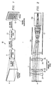
- FIGUREs 2 and 3 are a top view and an isometric view, respectively, of an anamorphic lens 11. It is placed in front of a projection lens 13, which has a primary lens 13a and prism 13b. The image is displayed on screen 14.
- Primary lens 13a puts the image on screen 14 at a desired throw ratio. For example, if primary lens 13a has a 7:1 throw ratio, a viewer 35 feet from the lens would see a 5 foot wide picture.
- the throw ratio associated with projection lens 13a is changed when anamorphic lens 11 is used. In the example of this description, where anamorphic lens 11 has a modification ratio of 1.5:1, the throw ratio is reduced by a factor of 1.5.
- Prism 13b is used with a display system having three spatial light modulators, which each concurrently generate a different color of the same image, red, green, or blue.
- Prism lens 13b combines the three images to provide a single full-color image.
- prism lens 13b would not be used.
- Anamorphic lens 11 is comprised of a series of five cylindrical lens elements 21 - 25. Elements 22 and 23 comprise a doublet, as do elements 24 and 25. The use of doublet elements is a feature that reduces light loss within the display system and increases the contrast ratio of the displayed image. In fact, lens 11 has been experimentally determined to have a transmission ratio of 96%.
- Element 21 is a cylindrical bi-concave lens.
- Elements 22 and 23 are a "meniscus", that is, a combination of convex and concave surfaces, as are elements 24 and 25.
- FIGURE 4 is a table that sets out the lens characteristics for the 1.5:1 embodiment of this description. Each of the surfaces is listed, and each surface corresponds to a surface in FIGUREs 2 and 3, from left to right.
- the surface type "toroidal" is a generic classification that includes the cylindrical surface type of lens elements 21 - 25. The various dimensions are in millimeters.
- the "diameter" parameter is for purposes of example and primarily affects the size of the image to be displayed.
- anamorphic lens 11 modifies the aspect of the image it receives (herein referred to as its aspect modification ratio) is determined by a number of factors. These include the radius, thickness, and type of glass of each element of lens 11. Thus, the same configuration of lens elements 21 - 25 could be modified so as to have a different optical prescription thereby providing other modification ratios.
- the air space between lenses 23 and 24 varies from approximately 64 to 72 millimeters. Adjustment of this air space permits the displayed image to be focussed in the horizontal dimension.
- the image from projection lens 13 is first focussed without anamorphic lens 11. The image will be focussed in both dimensions but squeezed in the horizontal dimension. Then, lens 11 is placed in the optical path. The image focus in the vertical dimension will not be affected, but by varying the air space, the focus in the horizontal dimension is adjusted and the image is stretched (“unsqueezed”) horizontally.
- the adjustability of the air space permits the same prescription of lens 11 to be used with a variety of projection lenses 13.
- lens 11 can be focussed to accommodate a particular projection lenses 13.
- the projection lens throw ratio may vary anywhere from 10:1 to 3:1.
- a further feature is that the same prescription can be used for SLMs having different aspect ratios.
- a 1.5:1 lens 11 has been satisfactorily tested with both a 4:3 and a 5:4 DMD, providing 2:1 and 1.85: images, respectively.
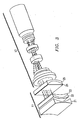
- FIGURE 5 is another example of lens 11, for a projection lens 13 having a different throw ratio than that of FIGURE 3.
- FIGURE 5 further illustrates that one or more elements of lens 11 may be round as well as square.
- elements 24 and 25 are round. This design choice is a function of the size of the image to be displayed. The dimensions of each element are also illustrated.
- the optical prescription is the same except for an adjustment of the air space between elements 23 and 24.
- the same lens 11 can provide the same modification ratio to an image projected by a different projection lens.
Landscapes
- Physics & Mathematics (AREA)
- General Physics & Mathematics (AREA)
- Optics & Photonics (AREA)
- Lenses (AREA)
- Projection Apparatus (AREA)
Abstract
Description
- This invention generally relates to optical devices and more particularly to an anamorphic lens that resizes the image to a wider aspect ratio than that of a spatial light modulator for a display system.
- One type of display system is a projection display system, where a projection lens is used to project the image to a screen. Movie theaters are one example of such display systems on a large scale. More recently, television sets and digital cinema systems have been developed that also use projection lenses. The projection lens may be for either front or rear projection, depending on whether the lens is on the viewer side of the screen or behind the screen.
- Spatial light modulators (SLMs) are a type of display device that may use a projection lens. In general, SLMs are arrays of pixel-generating elements that emit or reflect light to the display screen via the projection lens. The SLM modulates light by turning the pixel-generating elements "ON" or "OFF".
- An example of an SLM is a DMD (digital micro-mirror device). A DMD is an electromechanical device, whose pixel-generating elements form an array of hundreds or thousands of tiny tilting mirrors. To permit the mirrors to tilt, each is attached to one or more hinges mounted on support posts, and spaced by means of an air gap over underlying control circuitry. The control circuitry provides electrostatic forces, which cause each mirror to selectively tilt. Incident light on the mirror array is reflected by the "ON" mirrors in one direction and by the "OFF" mirrors in the other direction. The pattern of "ON" versus "OFF" mirrors forms an image. In most applications, the light from the DMD is projected by a projection lens to a screen.
- The size of the array of an SLM's pixel-generating elements determines the aspect ratio of the image it generates. For example, an SLM might have an array size of 1024 x 768, thereby generating images with an aspect ratio of 4:3. This 4:3 aspect ratio is consistent with NTSC television broadcast signals as well as those used for personal computer displays.
- As display systems become more advanced, the variety of source data that they are capable of displaying has increased. Each type of source data may have its own format, that is, its own aspect ratio and vertical and horizontal resolution. For example, one advance is the availability of "digital cinema", in which movie films are digitized for display. Movie films are characterized by a wide aspect ratio, such as 2:1. Another advance is high definition television with wide aspect ratios, such as the 16:9 format.
- The obvious approach to using an SLM to display images having a desired aspect ratio is to use an SLM that has the same aspect ratio. Thus, a 2:1 image would be displayed with a 2:1 SLM. However, this approach requires a different SLM to be manufactured for each format having a different aspect ratio.
- Another approach is to use an SLM that has a different aspect ratio but to forego use of the entire array. An example of this approach is the "letterbox" display, where a movie image is displayed with blank bands at the top and bottom. However, this approach is inefficient and the picture is distracting.
- A third approach is to use an anamorphic lens to stretch the image to fit the desired aspect ratio. However, a problem with existing anamorphic lenses is that they are designed for a particular projection lens and are not likely to operate with a different projection lens. Also, existing anamorphic lenses are designed for large scale projectors where compactness and cost are not overriding considerations.
- One aspect of the invention is an anamorphic lens for use in a display system having a spatial light modulator for generating images and a projection lens for projecting the image to a screen. The spatial light modulator has an associated aspect ratio, which need not match the aspect ratio of the images to be displayed, and generates an image that is "squeezed" in one dimension. The anamorphic lens has a series of lens elements in the optical path between screen and the projector. The first lens element is a bi-concave lens. A second lens element is spaced from the first lens element and has a first surface that is convex. A third lens element also has a first surface that is convex, and the second lens and third lens form a doublet. A fourth lens element is spaced from the third lens element, thereby forming an air space, and has a first surface that is planar. A fifth lens element has a first surface that is concave, and the fourth lens and the fifth lens also form a doublet. The anamorphic lens is operable to "unsqueeze" the image to fill one dimension of a desired aspect ratio.
- An advantage of the invention is that it permits a single SLM to be used for a variety of display formats. For example, a 4:3 SLM can be used to display 2:1 movie films. The picture quality of the anamorphically stretched image is comparable to that produced by conventional movie projection lenses.
- The anamorphic lens can have a particular optical prescription (lens radii, glass type, etc) that is adjustable for use with different projection lenses. Specifically, a particular prescription has been tested to be useful with projection lenses having throw ratios in a range of 7:1 down to 3:1.
- Furthermore, the same basic five-element lens configuration can be used with SLMs having different aspect ratios. For example, the same basic configuration has been implemented in a 1.5:1 form for use with both 4:3 and 5:4 SLMs to provide 2:1 and 1.85:1 images, respectively.
- Therefore, the invention provides a versatile, low cost, compact, and efficient solution to the problem of displaying wide images on SLMs.
- The present invention will now be further described, by way of example, with reference to the accompanying drawings in which:
- FIGURE 1 illustrates a portion of a projection display system that has an anamorphic lens;
- FIGUREs 2 and 3 are a top view and isometric view, respectively, of the anamorphic lens of FIGURE 1.
- FIGURE 4 is a table that sets out the optical characteristics of the anamorphic lens of FIGURE 1.
- FIGURE 5 is another example of the anamorphic lens of FIGURE 1.
-
- The following description is directed to an anamorphic lens that is used with a display system that uses at least one SLM to generate the image. In general, the invention recognizes that the image can be "squeezed" when generated by the SLM and then optically widened to provide wide-screen images, such as those associated with movie films. The anamorphic lens permits the entire SLM array to be active. Thus, the same SLM can be used to display both "television" and movie images without loss of picture size and light efficiency.
- FIGURE 1 illustrates a portion of a
typical display system 10, with which theanamorphic lens 11 may be used. An SLM 12 generates an image, which is projected by aprojection lens 13 through theanamorphic lens 11 to the screen 14. Thus,anamorphic lens 11 is in the optical path betweenprojection lens 13 and the screen 14. - As stated in the Background,
SLM 12 has an associated aspect ratio. In the example of FIGURE 1, the aspect ratio ofSLM 12 is 4:3. Theanamorphic lens 11 has an aspect ratio modification ratio, which in the example of FIGURE 1, is 1.5:1. As a result, the displayed image has an aspect ratio of 2:1. However, the invention is not limited to a 4:3 display device. Nor is it limited to alens 11 with a modification ratio of 1.5:1. -
SLM 12 is assumed to be capable of generating an image that is "squeezed" in the horizontal dimension, that is, an image that requires an anamorphic lens in order to look normal. The squeezed image could be the result of the manner in which the source image is recorded or it could be the result of some sort of processing within thedisplay system 10. The amount that the image is squeezed substantially corresponds to the modification factor of thelens 11. Thus, in the example of FIGURE 1, the 4:3 image generated bySLM 12 is squeezed in the horizontal dimension by a factor of 1.5. - DMD's, a type of SLM, are especially suited for use with
anamorphic lens 11. Examples of DMD-based display systems, without the anamorphic lens disclosed herein, are described in U.S. Patent No. 5,079,544, entitled "Standard Independent Digitized Video System," in U.S. Patent No. 5,526,051, entitled "Digital Television System," and in U.S. Patent No. 5,452,024, entitled "DMD Display System". U.S. Patent No. 5,796,442, entitled "A Multi-Format Television Architecture", describes various processing techniques associated with displaying different formats with the same DMD. Each of these inventions is assigned to Texas Instruments Incorporated, and each is incorporated by referenced herein. - In the example of FIGURE 1, a
single SLM 12 generates the image, and can provide full-color images by means of a color wheel (not shown). However, as explained below in connection with FIGURE 2, an alternative method of providing color images is to use multiple DMD's and combine their images optically. - FIGUREs 2 and 3 are a top view and an isometric view, respectively, of an
anamorphic lens 11. It is placed in front of aprojection lens 13, which has a primary lens 13a andprism 13b. The image is displayed on screen 14. - Primary lens 13a puts the image on screen 14 at a desired throw ratio. For example, if primary lens 13a has a 7:1 throw ratio, a viewer 35 feet from the lens would see a 5 foot wide picture. The throw ratio associated with projection lens 13a is changed when
anamorphic lens 11 is used. In the example of this description, whereanamorphic lens 11 has a modification ratio of 1.5:1, the throw ratio is reduced by a factor of 1.5. -
Prism 13b is used with a display system having three spatial light modulators, which each concurrently generate a different color of the same image, red, green, or blue.Prism lens 13b combines the three images to provide a single full-color image. For a display system that uses a single spatiallight modulator 12, such assystem 10 of FIGURE 1,prism lens 13b would not be used. -
Anamorphic lens 11 is comprised of a series of five cylindrical lens elements 21 - 25.Elements elements lens 11 has been experimentally determined to have a transmission ratio of 96%. -
Element 21 is a cylindrical bi-concave lens.Elements elements - FIGURE 4 is a table that sets out the lens characteristics for the 1.5:1 embodiment of this description. Each of the surfaces is listed, and each surface corresponds to a surface in FIGUREs 2 and 3, from left to right. The surface type "toroidal" is a generic classification that includes the cylindrical surface type of lens elements 21 - 25. The various dimensions are in millimeters.
- As indicated in FIGURE 4, there are a number of surfaces, with an air space between
elements elements - The extent to which
anamorphic lens 11 modifies the aspect of the image it receives (herein referred to as its aspect modification ratio) is determined by a number of factors. These include the radius, thickness, and type of glass of each element oflens 11. Thus, the same configuration of lens elements 21 - 25 could be modified so as to have a different optical prescription thereby providing other modification ratios. - The air space between
lenses projection lens 13 is first focussed withoutanamorphic lens 11. The image will be focussed in both dimensions but squeezed in the horizontal dimension. Then,lens 11 is placed in the optical path. The image focus in the vertical dimension will not be affected, but by varying the air space, the focus in the horizontal dimension is adjusted and the image is stretched ("unsqueezed") horizontally. - The adjustability of the air space permits the same prescription of
lens 11 to be used with a variety ofprojection lenses 13. By changing the distance of the variable air space,lens 11 can be focussed to accommodate aparticular projection lenses 13. For example, it has been experimentally determined that the projection lens throw ratio may vary anywhere from 10:1 to 3:1. - A further feature is that the same prescription can be used for SLMs having different aspect ratios. For example, a 1.5:1
lens 11 has been satisfactorily tested with both a 4:3 and a 5:4 DMD, providing 2:1 and 1.85: images, respectively. - FIGURE 5 is another example of
lens 11, for aprojection lens 13 having a different throw ratio than that of FIGURE 3. FIGURE 5 further illustrates that one or more elements oflens 11 may be round as well as square. Here,elements elements same lens 11 can provide the same modification ratio to an image projected by a different projection lens. - Although the invention has been described with reference to specific embodiments, this description is not meant to be construed in a limiting sense. Various modifications of the disclosed embodiments, as well as alternative embodiments, will be apparent to persons skilled in the art.
Claims (6)
- An anamorphic lens for use in a display system having a spatial light modulator for generating images and a projection lens for projecting the image to a screen, said spatial light modulator having an associated aspect ratio, and said screen and said projection lens having an optical path between them, comprising:a plurity of lens elements disposed in an optical path between the screen and the projection lens, said plurality comprising:a first lens element that is a bi-concave lens;a second lens element spaced from said first lens element and having a first surface that is convex;a third lens element having a first surface that is convex, said second lens and said third lens forming a doublet;a fourth lens element spaced from said third lens element, thereby forming an air space, and having a first surface that is planar; anda fifth lens element having a first surface that is concave, wherein said fourth lens and said fifth lens form a doublet.
- The anamorphic lens of Claim 1, wherein said lens is arranged for use in a spatial light modulator having a 4:3 aspect ratio.
- The anamorphic lens of Claim 1, wherein said lens is arranged for use in a spatial light modulator having a 5:4 aspect ratio.
- The anamorphic lens of any of Claims 1 to 3, wherein said anamorphic lens modifies said aspect ratio of said spatial light modulator by 1.5:1.
- The anamorphic lens of any of Claims 1 to 4, wherein said air space between said third lens element and said fourth lens element may be adjusted to accommodate a projection lens having a throw ratio substantially in the range of 7:1 to 3:1.
- A method of displaying a wide-screen image with a display system having a spatial light modulator for generating the image and a projection lens for projecting the image to a screen, said spatial light modulator having an associated aspect ratio, and said screen and said projection lens having an optical path there between, comprising:arranging a plurality of lens elements in an optical path between the screen and the projection lens, wherein said arranging step comprises;providing a first lens element that is a bi-concave lens;spacing a second lens element said first lens element having a first surface that is convex;forming a meniscus with a third lens element having a first surface that is convex, and with said second lens;spacing a fourth lens element from said third lens element, thereby forming an air space, said fourth lens element having a first surface that is planar; andforming a meniscus with a fifth lens element having a first surface that is concave, wherein said fourth lens element; andadjusting said air space between said third lens and said fourth lens.
Applications Claiming Priority (2)
| Application Number | Priority Date | Filing Date | Title |
|---|---|---|---|
| US6287297P | 1997-10-21 | 1997-10-21 | |
| US62872P | 1997-10-21 |
Publications (2)
| Publication Number | Publication Date |
|---|---|
| EP0911666A2 true EP0911666A2 (en) | 1999-04-28 |
| EP0911666A3 EP0911666A3 (en) | 1999-09-22 |
Family
ID=22045400
Family Applications (1)
| Application Number | Title | Priority Date | Filing Date |
|---|---|---|---|
| EP98308553A Withdrawn EP0911666A3 (en) | 1997-10-21 | 1998-10-19 | Improvements in or relating to optical devices |
Country Status (2)
| Country | Link |
|---|---|
| US (1) | US5930050A (en) |
| EP (1) | EP0911666A3 (en) |
Cited By (4)
| Publication number | Priority date | Publication date | Assignee | Title |
|---|---|---|---|---|
| FR3047294A1 (en) * | 2016-02-02 | 2017-08-04 | Valeo Vision | OPTICAL SINGLE COLLIMATION FOR COHERENT LIGHT SOURCE |
| US10436409B2 (en) | 2015-05-28 | 2019-10-08 | Texas Instruments Incorporated | Methods and apparatus for light efficient programmable headlamp with anamorphic optics |
| WO2022032855A1 (en) * | 2020-08-14 | 2022-02-17 | 广东思锐光学股份有限公司 | Mobile terminal having built-in anamorphic lens |
| EP3350506B1 (en) * | 2015-09-15 | 2023-11-15 | Valeo Vision | Light-beam-projecting device of a vehicle and vehicle headlamp comprising it |
Families Citing this family (67)
| Publication number | Priority date | Publication date | Assignee | Title |
|---|---|---|---|---|
| US6969635B2 (en) * | 2000-12-07 | 2005-11-29 | Reflectivity, Inc. | Methods for depositing, releasing and packaging micro-electromechanical devices on wafer substrates |
| US6317171B1 (en) * | 1997-10-21 | 2001-11-13 | Texas Instruments Incorporated | Rear-screen projection television with spatial light modulator and positionable anamorphic lens |
| US6587159B1 (en) * | 1998-05-29 | 2003-07-01 | Texas Instruments Incorporated | Projector for digital cinema |
| US6962419B2 (en) | 1998-09-24 | 2005-11-08 | Reflectivity, Inc | Micromirror elements, package for the micromirror elements, and projection system therefor |
| US6561649B1 (en) * | 1999-07-09 | 2003-05-13 | Sarnoff Corporation | Compact rear projection system using birefringent optics |
| US6181482B1 (en) | 1999-09-08 | 2001-01-30 | News America Incorporated | Variable ratio anamorphic lens |
| JP2001159733A (en) * | 1999-12-02 | 2001-06-12 | Fuji Photo Optical Co Ltd | Image pickup auxiliary lens and image pickup device using the same |
| US6791578B1 (en) * | 2000-05-30 | 2004-09-14 | Apple Computer, Inc. | 16:9 aspect ratio and anamorphic image processing |
| US7167297B2 (en) * | 2000-08-30 | 2007-01-23 | Reflectivity, Inc | Micromirror array |
| DE10060072A1 (en) | 2000-12-01 | 2002-06-06 | Jos Schneider Optische Werke G | Compact anamorphotic objective for digital projection of electronic images has afocal lens group infront of projection objective followed immediately by second lens group with at least one cylindrical lens |
| US6585378B2 (en) | 2001-03-20 | 2003-07-01 | Eastman Kodak Company | Digital cinema projector |
| US7023606B2 (en) * | 2001-08-03 | 2006-04-04 | Reflectivity, Inc | Micromirror array for projection TV |
| GB2382880A (en) * | 2001-12-10 | 2003-06-11 | Wynne Willson Gottelier Ltd | Colour projector with movable colour filters and elliptical mask window |
| US6909473B2 (en) | 2002-01-07 | 2005-06-21 | Eastman Kodak Company | Display apparatus and method |
| US7061561B2 (en) * | 2002-01-07 | 2006-06-13 | Moxtek, Inc. | System for creating a patterned polarization compensator |
| US6808269B2 (en) * | 2002-01-16 | 2004-10-26 | Eastman Kodak Company | Projection apparatus using spatial light modulator |
| US6676260B2 (en) | 2002-04-25 | 2004-01-13 | Eastman Kodak Company | Projection apparatus using spatial light modulator with relay lens and dichroic combiner |
| US6648475B1 (en) | 2002-05-20 | 2003-11-18 | Eastman Kodak Company | Method and apparatus for increasing color gamut of a display |
| US6736514B2 (en) * | 2002-06-21 | 2004-05-18 | Eastman Kodak Company | Imaging apparatus for increased color gamut using dual spatial light modulators |
| US6809873B2 (en) * | 2002-09-09 | 2004-10-26 | Eastman Kodak Company | Color illumination system for spatial light modulators using multiple double telecentric relays |
| US6769772B2 (en) * | 2002-10-11 | 2004-08-03 | Eastman Kodak Company | Six color display apparatus having increased color gamut |
| US6802613B2 (en) * | 2002-10-16 | 2004-10-12 | Eastman Kodak Company | Broad gamut color display apparatus using an electromechanical grating device |
| US6807010B2 (en) * | 2002-11-13 | 2004-10-19 | Eastman Kodak Company | Projection display apparatus having both incoherent and laser light sources |
| US20040150794A1 (en) * | 2003-01-30 | 2004-08-05 | Eastman Kodak Company | Projector with camcorder defeat |
| US7042622B2 (en) * | 2003-10-30 | 2006-05-09 | Reflectivity, Inc | Micromirror and post arrangements on substrates |
| US7098936B2 (en) * | 2003-03-11 | 2006-08-29 | Hewlett-Packard Development Company, L.P. | Image display system and method including optical scaling |
| US6758565B1 (en) | 2003-03-20 | 2004-07-06 | Eastman Kodak Company | Projection apparatus using telecentric optics |
| US7221759B2 (en) * | 2003-03-27 | 2007-05-22 | Eastman Kodak Company | Projector with enhanced security camcorder defeat |
| US7006630B2 (en) * | 2003-06-03 | 2006-02-28 | Matsushita Electric Industrial Co., Ltd. | Methods and apparatus for digital content protection |
| US6839181B1 (en) * | 2003-06-25 | 2005-01-04 | Eastman Kodak Company | Display apparatus |
| US6902277B1 (en) | 2004-01-06 | 2005-06-07 | Eastman Kodak Company | Housing for a spatial light modulator |
| US7961393B2 (en) | 2004-12-06 | 2011-06-14 | Moxtek, Inc. | Selectively absorptive wire-grid polarizer |
| US7800823B2 (en) | 2004-12-06 | 2010-09-21 | Moxtek, Inc. | Polarization device to polarize and further control light |
| US7570424B2 (en) | 2004-12-06 | 2009-08-04 | Moxtek, Inc. | Multilayer wire-grid polarizer |
| US7529026B2 (en) * | 2005-04-28 | 2009-05-05 | Hewlett-Packard Development Company, L.P. | Optical system with nanoscale projection antireflection layer/embossing |
| US20060279708A1 (en) * | 2005-06-13 | 2006-12-14 | Eastman Kodak Company | Electronic display apparatus having adaptable color gamut |
| US7289272B2 (en) | 2005-09-16 | 2007-10-30 | Raytheon Company | Optical system including an anamorphic lens |
| US8755113B2 (en) | 2006-08-31 | 2014-06-17 | Moxtek, Inc. | Durable, inorganic, absorptive, ultra-violet, grid polarizer |
| US8132920B2 (en) | 2007-03-19 | 2012-03-13 | Motorola Mobility, Inc. | Thin microprojector with switched beam bender and method of operating the same |
| US20080239170A1 (en) * | 2007-03-26 | 2008-10-02 | Motorola, Inc. | Low profile, high efficiency projector for handheld electronic devices |
| US7789515B2 (en) | 2007-05-17 | 2010-09-07 | Moxtek, Inc. | Projection device with a folded optical path and wire-grid polarizer |
| US20090122272A1 (en) * | 2007-11-09 | 2009-05-14 | Silverstein Barry D | Projection apparatus using solid-state light source array |
| US20090153752A1 (en) * | 2007-12-14 | 2009-06-18 | Silverstein Barry D | Projector using independent multiple wavelength light sources |
| US20090257030A1 (en) * | 2008-04-10 | 2009-10-15 | Motorola, Inc. | Image projector with time-sequential interlacing |
| JP2009300526A (en) * | 2008-06-10 | 2009-12-24 | Konica Minolta Opto Inc | Anamorphic converter and image projection system |
| WO2010065565A2 (en) | 2008-12-01 | 2010-06-10 | Reald Inc. | Stereoscopic projection systems and methods for employing spatial multiplexing at an intermediate image plane |
| US8066389B2 (en) * | 2009-04-30 | 2011-11-29 | Eastman Kodak Company | Beam alignment chamber providing divergence correction |
| US8132919B2 (en) * | 2009-04-30 | 2012-03-13 | Eastman Kodak Company | Digital projector using arrayed light sources |
| US8033666B2 (en) | 2009-05-28 | 2011-10-11 | Eastman Kodak Company | Beam alignment system using arrayed light sources |
| US8248696B2 (en) | 2009-06-25 | 2012-08-21 | Moxtek, Inc. | Nano fractal diffuser |
| JP2012532341A (en) | 2009-06-29 | 2012-12-13 | リアルディー インコーポレイテッド | Stereoscopic projection system using spatial multiplexing on the intermediate image plane |
| US8220931B2 (en) | 2009-07-07 | 2012-07-17 | Eastman Kodak Company | Etendue reduced stereo projection using segmented disk |
| US8066382B2 (en) * | 2009-07-14 | 2011-11-29 | Eastman Kodak Company | Stereoscopic projector with rotating segmented disk |
| US8688826B2 (en) * | 2009-11-30 | 2014-04-01 | Motorola Mobility Llc | Mobile computing device and method with intelligent pushing management |
| US8611007B2 (en) | 2010-09-21 | 2013-12-17 | Moxtek, Inc. | Fine pitch wire grid polarizer |
| US8913321B2 (en) | 2010-09-21 | 2014-12-16 | Moxtek, Inc. | Fine pitch grid polarizer |
| TWI421558B (en) | 2010-12-10 | 2014-01-01 | Delta Electronics Inc | Projection lens of an imaging module and imaging module |
| US8913320B2 (en) | 2011-05-17 | 2014-12-16 | Moxtek, Inc. | Wire grid polarizer with bordered sections |
| US8873144B2 (en) | 2011-05-17 | 2014-10-28 | Moxtek, Inc. | Wire grid polarizer with multiple functionality sections |
| US8922890B2 (en) | 2012-03-21 | 2014-12-30 | Moxtek, Inc. | Polarizer edge rib modification |
| DE102013102910B3 (en) * | 2013-03-21 | 2014-02-13 | Jos. Schneider Optische Werke Gmbh | Anamorphic lens attachment for use in anamorphic lens for cinemascope-cinema technology for recording and projection of wide screen movies, has end lens axially displaceable relative to front lens and to cemented elements |
| US9354374B2 (en) | 2013-10-24 | 2016-05-31 | Moxtek, Inc. | Polarizer with wire pair over rib |
| KR102595295B1 (en) * | 2016-08-12 | 2023-10-30 | 엘지전자 주식회사 | Projector |
| WO2019073343A1 (en) * | 2017-10-11 | 2019-04-18 | Volfoni R&D | Stereoscopic three dimensional projection system with short throw ratio |
| WO2020223047A1 (en) | 2019-04-30 | 2020-11-05 | Flir Commercial Systems, Inc. | Aspect ratio modifying imaging systems and methods |
| CN110716290A (en) * | 2019-09-26 | 2020-01-21 | 广东思锐光学股份有限公司 | Deformation lens |
| US20220196995A1 (en) * | 2020-12-23 | 2022-06-23 | Zhongshan AZU Optoelectronics Technology Co., Ltd. | Full-frame anamorphic lens |
Citations (4)
| Publication number | Priority date | Publication date | Assignee | Title |
|---|---|---|---|---|
| US2944464A (en) * | 1957-10-31 | 1960-07-12 | Scanoptic Inc | Anamorphic lens system |
| DE3434706A1 (en) * | 1984-09-21 | 1986-03-27 | Isco-Optic GmbH, 3400 Göttingen | Anamorphic projection lens for home projectors |
| US5339193A (en) * | 1991-08-17 | 1994-08-16 | Jos. Schneider Optische Werke Kreuznach Gmbh & Co. Kg | Anamorphotic attachment for a projection objective |
| US5648871A (en) * | 1991-06-28 | 1997-07-15 | Canon Kabushiki Kaisha | Projection apparatus utilizing an anamorphic optical system |
Family Cites Families (26)
| Publication number | Priority date | Publication date | Assignee | Title |
|---|---|---|---|---|
| US2531399A (en) * | 1946-04-27 | 1950-11-28 | Farnsworth Res Corp | Television projection system and viewing screen |
| US2924145A (en) * | 1953-12-16 | 1960-02-09 | Applic Tech Et D Expl Cinemato | Apparatus for anamorphotical kinematographic projection and view-taking |
| US2752821A (en) * | 1954-02-05 | 1956-07-03 | Taylor Taylor & Hobson Ltd | Wide angle anamorphotic attachments for optical objectives |
| US3565511A (en) * | 1969-04-23 | 1971-02-23 | Baus Optics Inc | Telecentric lens system for providing an image with the principal rays parallel to the optical axis and normal to the focal plane |
| US3644037A (en) * | 1969-04-28 | 1972-02-22 | Ck Optical Co Inc | Anamorphic lens systems |
| DE2043193C3 (en) * | 1970-09-01 | 1980-10-30 | Kurt 2000 Hamburg Kirchhoff | Anamorphic lens with adjustable focal length |
| US3658410A (en) * | 1971-02-08 | 1972-04-25 | Us Navy | Wide angle anamorphic refractive lenses |
| GB1366147A (en) * | 1971-12-13 | 1974-09-11 | Redifon Ltd | Optical systems for the display of visual images |
| US3990785A (en) * | 1972-09-22 | 1976-11-09 | Canon Kabushiki Kaisha | Anamorphic zoom lens |
| JPS4974954A (en) * | 1972-11-17 | 1974-07-19 | ||
| US4805998A (en) * | 1987-11-13 | 1989-02-21 | Chen Ying T | Variable anamorphic lens system |
| US5028939A (en) * | 1988-08-23 | 1991-07-02 | Texas Instruments Incorporated | Spatial light modulator system |
| US5079544A (en) * | 1989-02-27 | 1992-01-07 | Texas Instruments Incorporated | Standard independent digitized video system |
| DE3909203C1 (en) * | 1989-03-21 | 1990-04-26 | Isco-Optic Gmbh, 3400 Goettingen, De | |
| US5191474A (en) * | 1989-05-18 | 1993-03-02 | Minolta Camera Kabushiki Kaisha | Anamorphic illuminating optical system |
| US5260831A (en) * | 1989-05-18 | 1993-11-09 | Minolta Camera Kabushiki Kaisha | Anamorphic illuminating optical system |
| US5184223A (en) * | 1990-04-28 | 1993-02-02 | Olympus Optical Co., Ltd. | Electronic imaging apparatus |
| US5673086A (en) * | 1990-10-05 | 1997-09-30 | Canon Kabushiki Kaisha | Image aspect ratio conversion processing apparatus |
| JP3094529B2 (en) * | 1991-08-27 | 2000-10-03 | 株式会社日立製作所 | Image projection system and projection display device |
| US5579064A (en) * | 1991-12-12 | 1996-11-26 | Richard Vetter | Compact anamorphic motion picture system |
| US5504514A (en) * | 1992-02-13 | 1996-04-02 | Texas Instruments Incorporated | System and method for solid state illumination for spatial light modulators |
| US5526051A (en) * | 1993-10-27 | 1996-06-11 | Texas Instruments Incorporated | Digital television system |
| US5452024A (en) * | 1993-11-01 | 1995-09-19 | Texas Instruments Incorporated | DMD display system |
| US5671093A (en) * | 1993-11-18 | 1997-09-23 | Jung; Jin-Ho | Anamorphic lens for a CCD camera apparatus |
| US5796442A (en) * | 1994-11-02 | 1998-08-18 | Texas Instruments Incorporated | Multi-format television reciever |
| EP0837350A1 (en) * | 1995-04-26 | 1998-04-22 | Texas Instruments Incorporated | Improvements relating to illumination optics for spatial light modulator |
-
1998
- 1998-09-16 US US09/153,991 patent/US5930050A/en not_active Expired - Lifetime
- 1998-10-19 EP EP98308553A patent/EP0911666A3/en not_active Withdrawn
Patent Citations (4)
| Publication number | Priority date | Publication date | Assignee | Title |
|---|---|---|---|---|
| US2944464A (en) * | 1957-10-31 | 1960-07-12 | Scanoptic Inc | Anamorphic lens system |
| DE3434706A1 (en) * | 1984-09-21 | 1986-03-27 | Isco-Optic GmbH, 3400 Göttingen | Anamorphic projection lens for home projectors |
| US5648871A (en) * | 1991-06-28 | 1997-07-15 | Canon Kabushiki Kaisha | Projection apparatus utilizing an anamorphic optical system |
| US5339193A (en) * | 1991-08-17 | 1994-08-16 | Jos. Schneider Optische Werke Kreuznach Gmbh & Co. Kg | Anamorphotic attachment for a projection objective |
Cited By (5)
| Publication number | Priority date | Publication date | Assignee | Title |
|---|---|---|---|---|
| US10436409B2 (en) | 2015-05-28 | 2019-10-08 | Texas Instruments Incorporated | Methods and apparatus for light efficient programmable headlamp with anamorphic optics |
| EP3350506B1 (en) * | 2015-09-15 | 2023-11-15 | Valeo Vision | Light-beam-projecting device of a vehicle and vehicle headlamp comprising it |
| FR3047294A1 (en) * | 2016-02-02 | 2017-08-04 | Valeo Vision | OPTICAL SINGLE COLLIMATION FOR COHERENT LIGHT SOURCE |
| EP3203305A1 (en) * | 2016-02-02 | 2017-08-09 | Valeo Vision | Simple collimating lens for a coherent light source |
| WO2022032855A1 (en) * | 2020-08-14 | 2022-02-17 | 广东思锐光学股份有限公司 | Mobile terminal having built-in anamorphic lens |
Also Published As
| Publication number | Publication date |
|---|---|
| EP0911666A3 (en) | 1999-09-22 |
| US5930050A (en) | 1999-07-27 |
Similar Documents
| Publication | Publication Date | Title |
|---|---|---|
| US5930050A (en) | Anamorphic lens for providing wide-screen images generated by a spatial light modulator | |
| US5467154A (en) | Projection monitor | |
| US6317171B1 (en) | Rear-screen projection television with spatial light modulator and positionable anamorphic lens | |
| US5692820A (en) | Projection monitor | |
| TW508953B (en) | Sequential color recapture for projection systems | |
| EP1257128B1 (en) | Projection-type display apparatus | |
| US5914818A (en) | Offset projection lens for use with reflective spatial light modulators | |
| US8025415B2 (en) | Projection optical system and image projecting apparatus | |
| US7946717B2 (en) | Projection optical system and image projecting apparatus | |
| US6343862B1 (en) | Projecting image display device | |
| US11573396B2 (en) | Multi-axis gimbal extended pixel resolution actuator | |
| US7055959B2 (en) | Projection display device and back projection display device using the display device | |
| US6619804B2 (en) | Optical engine for front or rear screen SLM display systems | |
| US7111943B2 (en) | Wide field display using a scanned linear light modulator array | |
| US7967448B2 (en) | Optical system for a thin, low-chin, projection television | |
| EP0704739A2 (en) | Image display systems | |
| US6094181A (en) | Miniature synthesized virtual image electronic display | |
| JPH08327900A (en) | Offset zoom lens for reflected-light modulator | |
| JP2004062209A (en) | Monocentric autostereoscopic optical display device having expanded color gamut | |
| EP1639409A2 (en) | Split image optical display | |
| CA2409254C (en) | Methods and systems for low loss separation and combination of light | |
| WO2008121924A1 (en) | Optical system for a thin, low-chin, projection television | |
| US8379322B2 (en) | Integrated asphere design for display | |
| US6208470B1 (en) | Telecentric projection lens | |
| JP2003057592A (en) | Picture display device |
Legal Events
| Date | Code | Title | Description |
|---|---|---|---|
| PUAI | Public reference made under article 153(3) epc to a published international application that has entered the european phase |
Free format text: ORIGINAL CODE: 0009012 |
|
| AK | Designated contracting states |
Kind code of ref document: A2 Designated state(s): DE FR GB IT NL |
|
| AX | Request for extension of the european patent |
Free format text: AL;LT;LV;MK;RO;SI |
|
| PUAL | Search report despatched |
Free format text: ORIGINAL CODE: 0009013 |
|
| AK | Designated contracting states |
Kind code of ref document: A3 Designated state(s): AT BE CH CY DE DK ES FI FR GB GR IE IT LI LU MC NL PT SE |
|
| AX | Request for extension of the european patent |
Free format text: AL;LT;LV;MK;RO;SI |
|
| 17P | Request for examination filed |
Effective date: 20000322 |
|
| AKX | Designation fees paid |
Free format text: DE FR GB IT NL |
|
| 17Q | First examination report despatched |
Effective date: 20030204 |
|
| STAA | Information on the status of an ep patent application or granted ep patent |
Free format text: STATUS: THE APPLICATION IS DEEMED TO BE WITHDRAWN |
|
| 18D | Application deemed to be withdrawn |
Effective date: 20030815 |