EP0911593A1 - Air separation plant and method of fabrication - Google Patents
Air separation plant and method of fabrication Download PDFInfo
- Publication number
- EP0911593A1 EP0911593A1 EP98308808A EP98308808A EP0911593A1 EP 0911593 A1 EP0911593 A1 EP 0911593A1 EP 98308808 A EP98308808 A EP 98308808A EP 98308808 A EP98308808 A EP 98308808A EP 0911593 A1 EP0911593 A1 EP 0911593A1
- Authority
- EP
- European Patent Office
- Prior art keywords
- air
- passage
- stream
- expansion
- distillation column
- Prior art date
- Legal status (The legal status is an assumption and is not a legal conclusion. Google has not performed a legal analysis and makes no representation as to the accuracy of the status listed.)
- Withdrawn
Links
Images


Classifications
-
- F—MECHANICAL ENGINEERING; LIGHTING; HEATING; WEAPONS; BLASTING
- F25—REFRIGERATION OR COOLING; COMBINED HEATING AND REFRIGERATION SYSTEMS; HEAT PUMP SYSTEMS; MANUFACTURE OR STORAGE OF ICE; LIQUEFACTION SOLIDIFICATION OF GASES
- F25J—LIQUEFACTION, SOLIDIFICATION OR SEPARATION OF GASES OR GASEOUS OR LIQUEFIED GASEOUS MIXTURES BY PRESSURE AND COLD TREATMENT OR BY BRINGING THEM INTO THE SUPERCRITICAL STATE
- F25J3/00—Processes or apparatus for separating the constituents of gaseous or liquefied gaseous mixtures involving the use of liquefaction or solidification
- F25J3/02—Processes or apparatus for separating the constituents of gaseous or liquefied gaseous mixtures involving the use of liquefaction or solidification by rectification, i.e. by continuous interchange of heat and material between a vapour stream and a liquid stream
- F25J3/04—Processes or apparatus for separating the constituents of gaseous or liquefied gaseous mixtures involving the use of liquefaction or solidification by rectification, i.e. by continuous interchange of heat and material between a vapour stream and a liquid stream for air
- F25J3/04763—Start-up or control of the process; Details of the apparatus used
- F25J3/04866—Construction and layout of air fractionation equipments, e.g. valves, machines
- F25J3/0489—Modularity and arrangement of parts of the air fractionation unit, in particular of the cold box, e.g. pre-fabrication, assembling and erection, dimensions, horizontal layout "plot"
-
- F—MECHANICAL ENGINEERING; LIGHTING; HEATING; WEAPONS; BLASTING
- F25—REFRIGERATION OR COOLING; COMBINED HEATING AND REFRIGERATION SYSTEMS; HEAT PUMP SYSTEMS; MANUFACTURE OR STORAGE OF ICE; LIQUEFACTION SOLIDIFICATION OF GASES
- F25J—LIQUEFACTION, SOLIDIFICATION OR SEPARATION OF GASES OR GASEOUS OR LIQUEFIED GASEOUS MIXTURES BY PRESSURE AND COLD TREATMENT OR BY BRINGING THEM INTO THE SUPERCRITICAL STATE
- F25J3/00—Processes or apparatus for separating the constituents of gaseous or liquefied gaseous mixtures involving the use of liquefaction or solidification
- F25J3/02—Processes or apparatus for separating the constituents of gaseous or liquefied gaseous mixtures involving the use of liquefaction or solidification by rectification, i.e. by continuous interchange of heat and material between a vapour stream and a liquid stream
- F25J3/04—Processes or apparatus for separating the constituents of gaseous or liquefied gaseous mixtures involving the use of liquefaction or solidification by rectification, i.e. by continuous interchange of heat and material between a vapour stream and a liquid stream for air
- F25J3/04151—Purification and (pre-)cooling of the feed air; recuperative heat-exchange with product streams
- F25J3/04187—Cooling of the purified feed air by recuperative heat-exchange; Heat-exchange with product streams
-
- F—MECHANICAL ENGINEERING; LIGHTING; HEATING; WEAPONS; BLASTING
- F25—REFRIGERATION OR COOLING; COMBINED HEATING AND REFRIGERATION SYSTEMS; HEAT PUMP SYSTEMS; MANUFACTURE OR STORAGE OF ICE; LIQUEFACTION SOLIDIFICATION OF GASES
- F25J—LIQUEFACTION, SOLIDIFICATION OR SEPARATION OF GASES OR GASEOUS OR LIQUEFIED GASEOUS MIXTURES BY PRESSURE AND COLD TREATMENT OR BY BRINGING THEM INTO THE SUPERCRITICAL STATE
- F25J3/00—Processes or apparatus for separating the constituents of gaseous or liquefied gaseous mixtures involving the use of liquefaction or solidification
- F25J3/02—Processes or apparatus for separating the constituents of gaseous or liquefied gaseous mixtures involving the use of liquefaction or solidification by rectification, i.e. by continuous interchange of heat and material between a vapour stream and a liquid stream
- F25J3/04—Processes or apparatus for separating the constituents of gaseous or liquefied gaseous mixtures involving the use of liquefaction or solidification by rectification, i.e. by continuous interchange of heat and material between a vapour stream and a liquid stream for air
- F25J3/04248—Generation of cold for compensating heat leaks or liquid production, e.g. by Joule-Thompson expansion
- F25J3/04284—Generation of cold for compensating heat leaks or liquid production, e.g. by Joule-Thompson expansion using internal refrigeration by open-loop gas work expansion, e.g. of intermediate or oxygen enriched (waste-)streams
- F25J3/0429—Generation of cold for compensating heat leaks or liquid production, e.g. by Joule-Thompson expansion using internal refrigeration by open-loop gas work expansion, e.g. of intermediate or oxygen enriched (waste-)streams of feed air, e.g. used as waste or product air or expanded into an auxiliary column
- F25J3/04296—Claude expansion, i.e. expanded into the main or high pressure column
-
- F—MECHANICAL ENGINEERING; LIGHTING; HEATING; WEAPONS; BLASTING
- F25—REFRIGERATION OR COOLING; COMBINED HEATING AND REFRIGERATION SYSTEMS; HEAT PUMP SYSTEMS; MANUFACTURE OR STORAGE OF ICE; LIQUEFACTION SOLIDIFICATION OF GASES
- F25J—LIQUEFACTION, SOLIDIFICATION OR SEPARATION OF GASES OR GASEOUS OR LIQUEFIED GASEOUS MIXTURES BY PRESSURE AND COLD TREATMENT OR BY BRINGING THEM INTO THE SUPERCRITICAL STATE
- F25J3/00—Processes or apparatus for separating the constituents of gaseous or liquefied gaseous mixtures involving the use of liquefaction or solidification
- F25J3/02—Processes or apparatus for separating the constituents of gaseous or liquefied gaseous mixtures involving the use of liquefaction or solidification by rectification, i.e. by continuous interchange of heat and material between a vapour stream and a liquid stream
- F25J3/04—Processes or apparatus for separating the constituents of gaseous or liquefied gaseous mixtures involving the use of liquefaction or solidification by rectification, i.e. by continuous interchange of heat and material between a vapour stream and a liquid stream for air
- F25J3/04248—Generation of cold for compensating heat leaks or liquid production, e.g. by Joule-Thompson expansion
- F25J3/04284—Generation of cold for compensating heat leaks or liquid production, e.g. by Joule-Thompson expansion using internal refrigeration by open-loop gas work expansion, e.g. of intermediate or oxygen enriched (waste-)streams
- F25J3/04309—Generation of cold for compensating heat leaks or liquid production, e.g. by Joule-Thompson expansion using internal refrigeration by open-loop gas work expansion, e.g. of intermediate or oxygen enriched (waste-)streams of nitrogen
-
- F—MECHANICAL ENGINEERING; LIGHTING; HEATING; WEAPONS; BLASTING
- F25—REFRIGERATION OR COOLING; COMBINED HEATING AND REFRIGERATION SYSTEMS; HEAT PUMP SYSTEMS; MANUFACTURE OR STORAGE OF ICE; LIQUEFACTION SOLIDIFICATION OF GASES
- F25J—LIQUEFACTION, SOLIDIFICATION OR SEPARATION OF GASES OR GASEOUS OR LIQUEFIED GASEOUS MIXTURES BY PRESSURE AND COLD TREATMENT OR BY BRINGING THEM INTO THE SUPERCRITICAL STATE
- F25J3/00—Processes or apparatus for separating the constituents of gaseous or liquefied gaseous mixtures involving the use of liquefaction or solidification
- F25J3/02—Processes or apparatus for separating the constituents of gaseous or liquefied gaseous mixtures involving the use of liquefaction or solidification by rectification, i.e. by continuous interchange of heat and material between a vapour stream and a liquid stream
- F25J3/04—Processes or apparatus for separating the constituents of gaseous or liquefied gaseous mixtures involving the use of liquefaction or solidification by rectification, i.e. by continuous interchange of heat and material between a vapour stream and a liquid stream for air
- F25J3/044—Processes or apparatus for separating the constituents of gaseous or liquefied gaseous mixtures involving the use of liquefaction or solidification by rectification, i.e. by continuous interchange of heat and material between a vapour stream and a liquid stream for air using a single pressure main column system only
-
- F—MECHANICAL ENGINEERING; LIGHTING; HEATING; WEAPONS; BLASTING
- F25—REFRIGERATION OR COOLING; COMBINED HEATING AND REFRIGERATION SYSTEMS; HEAT PUMP SYSTEMS; MANUFACTURE OR STORAGE OF ICE; LIQUEFACTION SOLIDIFICATION OF GASES
- F25J—LIQUEFACTION, SOLIDIFICATION OR SEPARATION OF GASES OR GASEOUS OR LIQUEFIED GASEOUS MIXTURES BY PRESSURE AND COLD TREATMENT OR BY BRINGING THEM INTO THE SUPERCRITICAL STATE
- F25J3/00—Processes or apparatus for separating the constituents of gaseous or liquefied gaseous mixtures involving the use of liquefaction or solidification
- F25J3/02—Processes or apparatus for separating the constituents of gaseous or liquefied gaseous mixtures involving the use of liquefaction or solidification by rectification, i.e. by continuous interchange of heat and material between a vapour stream and a liquid stream
- F25J3/04—Processes or apparatus for separating the constituents of gaseous or liquefied gaseous mixtures involving the use of liquefaction or solidification by rectification, i.e. by continuous interchange of heat and material between a vapour stream and a liquid stream for air
- F25J3/04763—Start-up or control of the process; Details of the apparatus used
- F25J3/04769—Operation, control and regulation of the process; Instrumentation within the process
- F25J3/04787—Heat exchange, e.g. main heat exchange line; Subcooler, external reboiler-condenser
-
- F—MECHANICAL ENGINEERING; LIGHTING; HEATING; WEAPONS; BLASTING
- F25—REFRIGERATION OR COOLING; COMBINED HEATING AND REFRIGERATION SYSTEMS; HEAT PUMP SYSTEMS; MANUFACTURE OR STORAGE OF ICE; LIQUEFACTION SOLIDIFICATION OF GASES
- F25J—LIQUEFACTION, SOLIDIFICATION OR SEPARATION OF GASES OR GASEOUS OR LIQUEFIED GASEOUS MIXTURES BY PRESSURE AND COLD TREATMENT OR BY BRINGING THEM INTO THE SUPERCRITICAL STATE
- F25J3/00—Processes or apparatus for separating the constituents of gaseous or liquefied gaseous mixtures involving the use of liquefaction or solidification
- F25J3/02—Processes or apparatus for separating the constituents of gaseous or liquefied gaseous mixtures involving the use of liquefaction or solidification by rectification, i.e. by continuous interchange of heat and material between a vapour stream and a liquid stream
- F25J3/04—Processes or apparatus for separating the constituents of gaseous or liquefied gaseous mixtures involving the use of liquefaction or solidification by rectification, i.e. by continuous interchange of heat and material between a vapour stream and a liquid stream for air
- F25J3/04763—Start-up or control of the process; Details of the apparatus used
- F25J3/04866—Construction and layout of air fractionation equipments, e.g. valves, machines
- F25J3/04896—Details of columns, e.g. internals, inlet/outlet devices
- F25J3/04927—Liquid or gas distribution devices
-
- F—MECHANICAL ENGINEERING; LIGHTING; HEATING; WEAPONS; BLASTING
- F25—REFRIGERATION OR COOLING; COMBINED HEATING AND REFRIGERATION SYSTEMS; HEAT PUMP SYSTEMS; MANUFACTURE OR STORAGE OF ICE; LIQUEFACTION SOLIDIFICATION OF GASES
- F25J—LIQUEFACTION, SOLIDIFICATION OR SEPARATION OF GASES OR GASEOUS OR LIQUEFIED GASEOUS MIXTURES BY PRESSURE AND COLD TREATMENT OR BY BRINGING THEM INTO THE SUPERCRITICAL STATE
- F25J2200/00—Processes or apparatus using separation by rectification
- F25J2200/72—Refluxing the column with at least a part of the totally condensed overhead gas
-
- F—MECHANICAL ENGINEERING; LIGHTING; HEATING; WEAPONS; BLASTING
- F25—REFRIGERATION OR COOLING; COMBINED HEATING AND REFRIGERATION SYSTEMS; HEAT PUMP SYSTEMS; MANUFACTURE OR STORAGE OF ICE; LIQUEFACTION SOLIDIFICATION OF GASES
- F25J—LIQUEFACTION, SOLIDIFICATION OR SEPARATION OF GASES OR GASEOUS OR LIQUEFIED GASEOUS MIXTURES BY PRESSURE AND COLD TREATMENT OR BY BRINGING THEM INTO THE SUPERCRITICAL STATE
- F25J2290/00—Other details not covered by groups F25J2200/00 - F25J2280/00
- F25J2290/10—Mathematical formulae, modeling, plot or curves; Design methods
-
- Y—GENERAL TAGGING OF NEW TECHNOLOGICAL DEVELOPMENTS; GENERAL TAGGING OF CROSS-SECTIONAL TECHNOLOGIES SPANNING OVER SEVERAL SECTIONS OF THE IPC; TECHNICAL SUBJECTS COVERED BY FORMER USPC CROSS-REFERENCE ART COLLECTIONS [XRACs] AND DIGESTS
- Y10—TECHNICAL SUBJECTS COVERED BY FORMER USPC
- Y10S—TECHNICAL SUBJECTS COVERED BY FORMER USPC CROSS-REFERENCE ART COLLECTIONS [XRACs] AND DIGESTS
- Y10S62/00—Refrigeration
- Y10S62/902—Apparatus
- Y10S62/903—Heat exchange structure
-
- Y—GENERAL TAGGING OF NEW TECHNOLOGICAL DEVELOPMENTS; GENERAL TAGGING OF CROSS-SECTIONAL TECHNOLOGIES SPANNING OVER SEVERAL SECTIONS OF THE IPC; TECHNICAL SUBJECTS COVERED BY FORMER USPC CROSS-REFERENCE ART COLLECTIONS [XRACs] AND DIGESTS
- Y10—TECHNICAL SUBJECTS COVERED BY FORMER USPC
- Y10S—TECHNICAL SUBJECTS COVERED BY FORMER USPC CROSS-REFERENCE ART COLLECTIONS [XRACs] AND DIGESTS
- Y10S62/00—Refrigeration
- Y10S62/902—Apparatus
- Y10S62/905—Column
- Y10S62/906—Packing
Definitions
- the present invention relates to an air separation plant or apparatus and to its fabrication.
- An air separation plant conventionally has a main heat exchanger to cool compressed and purified air to a temperature suitable for its distillation in a single or double distillation column.
- a double distillation column higher and lower pressure columns are operatively associated with one another in a heat transfer relationship by a condenser-reboiler.
- the air is distilled in the higher pressure column to separate nitrogen from the air and to produce an oxygen enriched liquid column bottom fraction which is further refined in the lower pressure column to produce nitrogen and oxygen products.
- the air is separated to produce a nitrogen product as an overhead fraction and a liquid fraction enriched in oxygen, which is expanded to a lower pressure (and therefore a lower temperature) to serve as a coolant to condense reflux.
- refrigeration can be provided by either expanding part of the incoming air, a waste stream, or part of a product stream. Such expansion produces a refrigerant stream.
- refrigerant stream is typically introduced into the distillation column or one or more of the distillation columns. Refrigerant streams originating from waste and product expansions are fed into the main heat exchanger and then fully warmed, ie to the warm end temperature of the main heat exchanger.
- the fabrication of air separation plants involves to a large extent the custom design and construction of its components.
- the main heat exchanger has an intermediate outlet for the air communicating with an expansion turbine.
- an intermediate outlet for the waste or product stream to be expanded is provided.
- Columns are also custom built, using precision components that must have a sufficient height to provide the number of stages of separation that are needed for the particular distillation involved. All of such custom design and construction adds to the cost of the fabrication of the air separation plant.
- An air separation plant has both capital and running costs. The smaller the plant (or apparatus) the more important it is to keep down capital costs.
- the present invention provides an air separation plant that can be constructed with prefabricated components to eliminate the added capital cost involved in custom design and construction of the components making up the air separation plant.
- the present invention provides in a first aspect an air separation plant comprising an air separation unit, an expansion machine and a main heat exchanger.
- the air separation unit has at least one distillation column to separate air into oxygen-rich and nitrogen-rich components and to produce at least two process streams composed of the oxygen and nitrogen-rich components.
- the expansion machine produces a refrigerant stream to refrigerate the air separation plant.
- the main heat exchanger has an air expansion passage to produce a partially cooled air stream, an air liquefaction passage branching from the air expansion passage to produce a liquefied air stream, at least two process stream passages, each sized to accommodate the at least two process streams both at column pressure and at a reduced pressure of the refrigerant stream.
- a process stream expansion passage configured to partially warm one of the at least two process streams.
- the air expansion passages are connected to the expansion machine and the expansion machine is connected to the air separation unit such that the resultant refrigerant stream is introduced into the air separation unit.
- the main heat exchanger is connected to the air separation unit to receive the at least two process streams within the at least two process stream passages and to introduce the liquefied air stream into the air separation unit. Additionally, the main heat exchanger is connected to the air separation unit such that the process stream expansion passage is unconnected and thus not utilized.
- the present invention provides an air separation plant in which the main heat exchanger is connected to the air separation unit in a manner that is different than that outlined above.
- the main heat exchanger is connected to the air separation unit so that one of the at least two process streams are received within the process stream expansion passage and another of the at least two process streams is received within one of the at least two process stream passages.
- the partially cooled air stream is introduced into an air separation unit and the air liquefaction passage is unconnected and therefore not utilized.
- the expansion machine is connected to the main heat exchanger to receive the one of the two process streams after having been partly warmed and so that the refrigerant stream is introduced into another of the at least two process stream passages.
- a main heat exchanger unitized within the present invention can function in either an air expansion plant, waste expansion plant or a nitrogen expansion plant.
- the present invention provides, in a third aspect, a method of fabricating an air separation plant with common components to function either with air, product or waste expansion.
- an air separation unit is provided having at least one distillation column to separate air into oxygen-rich and nitrogen-rich components and to produce at least two process streams composed of the oxygen and nitrogen-rich components.
- An expansion means is provided to produce a refrigerant stream to refrigerate the air separation plant. All the air separation plants are fabricated with the main heat exchanger having an air expansion passage to produce a partially cooled air stream, an air liquefaction passage branching off from the air expansion passage to liquefy an air stream, and at least two process stream passages.
- Each of the at least two process stream passages are sized to accommodate the at least two process streams to column pressure and at a reduced pressure of the refrigerant stream. Additionally provided is a process stream expansion passage configured to partially warm one of the two process streams. In case of air expansion, the expansion machine is connected to the air expansion passage and the process stream expansion passage is not utilized. In case of waste nitrogen expansion the expansion machine is connected to the process stream expansion passage and the air liquefaction passage is not utilized.
- the present invention provides in a fourth aspect a modular distillation column in which at least one section contains at least one bed of structured packing.
- a liquid distributor is located above the structured packing and comprises a container having a perforate bottom wall to distribute reflux to the structured packing.
- the container is telescoped within the pipe, in a spaced relationship thereto, so that the vapor passes between the container and the pipe.
- At least two support members are positioned within the section to hold the at least one bed of structured packing in place. In such manner, sections can be pre-fabricated and connected end to end to form the distillation column.
- the present invention provides a fifth aspect an air separation plant having the features set out in claim 12.
- an air separation plant 1 is illustrated. Air, after having been filtered in a filter 10, is compressed in a compressor 12. After the heat of compression is removed by an aftercooler 14, the air is further purified of moisture, carbon dioxide and other heavier components of the air by a prepurification unit 16. Prepurification unit 16 is preferably a cold trap designed to freeze out moisture and carbon dioxide. The resultant compressed and purified air stream is cooled within a main heat exchanger 18 and is then rectified at low temperature within a single distillation column 200 designed to produce an oxygen-rich liquid column bottoms and a nitrogen-rich overhead.
- Heat exchanger 18 is provided with an air expansion passage 20 (ie a passage which may be used to feed air to an air expander) , two process or product stream passages 22 and 24 and a product stream expansion passage 26 (ie a passage which may be used to feed nitrogen product or a waste oxygen-rich stream to an expansion machine.
- Main heat exchanger 18 is of plate-fin design and is designed to function in a plant that supplies refrigeration by air expansion, product expansion or waste expansion. (Each passage therefore typically comprises a set of channels). Further included in heat exchanger 18 is an air liquefaction passage 28.
- Air separation plant 1 is designed to function with air expansion and as such, air is partially cooled and discharged from main heat exchanger 18 through air expansion passage 20.
- the terms "partially cooled” or “partially warmed” mean cooled or warmed (as the context may be) to a temperature between the warm and cold end temperatures of main heat exchanger 18.
- the partially cooled air stream is expanded within a turboexpansion machine 30 and is introduced into a bottom section 32 of the distillation column 200 by way of an inlet distributor 33.
- a liquefied air stream is produced within air liquefaction passage 28. Such liquefied air stream is reduced in pressure in a valve 29 and is introduced into bottom region 32 of distillation column 200.
- valve 34 is provided which, when closed, causes all of the air to flow through air expansion passage 20.
- the valve 34 is therefore kept open during normal operation of the air separation plant.
- process steam expansion passage 26 left unconnected and, thus, is not utilized in the air separation plant 1.
- valves 36 and 38 are provided for main heat exchanger 18 in order to isolate the process stream expansion passage 26. The reason for providing the passage 26 in the heat exchanger 18, even though this passage is not used, will be explained below.
- the introduction of air into air separation unit 20 produces an ascending vapor phase that is contacted with a descending liquid phase by beds of structured packing 40 mounted on support 42.
- the descending liquid phase is produced by extracting a reflux stream 44 and condensing the reflux stream within head condenser 46 to form a condensed reflux stream 48 which is introduced into a top region 50 of distillation column 40.
- Outlet and inlet headers 52 and 54 are provided for such purpose.
- the liquid reflux is fed into a distributor 56 which is located or telescoped within the distillation column 200 such that a spacing exists between the column wall and liquid distributor 56.
- An arrangement of spaced blocks 58 connect liquid distributor 56 to the column sidewall of the distillation column 200.
- the coolant for head condenser 46 is oxygen enriched liquid which is taken from the column 200 and is expanded within an expansion valve 60.
- Resultant vaporized coolant stream 62 forms a process stream which is introduced into process stream passage 24 of main heat exchanger 18 where it is fully warmed and is discharged as waste.
- a product stream 64 composed of the nitrogen component produced within top region 50 of distillation column 200 is also introduced into main heat exchanger 18, within process stream passage 22, where it is thereafter expelled as product gas nitrogen (PGN).
- PPN product gas nitrogen
- the plant shown in Figure 1 is refrigerated by turbo-expansion of a part of the feed air. It is well known in the art that the optimum arrangement for the refrigeration of a nitrogen generator depends on a number of factors including the pressure at which the nitrogen product is required. On some occasions it is more desirable to expand the nitrogen product or the oxygen-rich product (waste) stream instead of a part of the air.
- FIG. 2 illustrates an air separation plant 1A that contains all of the elements of air separation plant 1.
- main heat exchanger 18 is connected so that the plant will now function as a waste (oxygen-rich product) expansion plant.
- vaporized coolant stream 62 is now introduced into process stream expansion passage 26.
- the vaporized coolant stream 62 after partial warming is introduced into a turboexpander 30 to produce a refrigerant stream.
- Turboexpander 30 is interposed so that the refrigerant stream is introduced into process stream passageway 24.
- Valve 34 is in its closed or cut-off position so that all the air flows through air expansion passageway 20 and is introduced as a vapor at or near its dewpoint into bottom region 32 of distillation column 20.
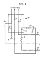
- Fig. 3 illustrates the connections in plant 1A that allow alternative operation as a product expansion plant.
- product stream 64 is introduced into process stream expansion passage 26 where it is partially warmed before being introduced into expansion machine 30.
- Valves 36 and 38 are set in open positions for such purpose.
- the resultant refrigerant stream is then introduced into process stream passageway 22 where it is expelled as product gas nitrogen.
- valve 34 is shut and left unconnected so that all of the air flows through air expansion passageway 20.
- the air at this point is cooled to at or near its dewpoint and it is introduced into bottom region 32 of distillation column 200.
- distillation column 200 is prefabricated by the use of one or more sections containing a bed 40 of structured packing.
- the bed 40 is held in place by supports 42 and 43.
- Liquid is distributed to the bed 40 of packing by liquid distributor 56 which is simply a cylindrical container which as shown in Fig. 4, has a perforate bottom wall 66 from which the liquid is distributed over the packing.
- support 42 As to support 42 (or support 43 for that matter) a simple construction is also employed. With reference to Figs. 5 and 6, support 42 is formed of an annular member 68 which is connected to column wall 70. The annulus is reinforced by a spider 72. The aforementioned arrangement can be pre-fabricated in a shop and then one or more sections can be used to form the required column. Although the illustrated section has only one bed 40 of packing, more beds could be used depending upon distillation requirements. Since each bed of packing is held in place by support members, such as 42 and 43, the column can be assembled in a fabrication shop and then shipped to the site at which the plant is to be erected without damage to the packing. It is to be noted that although the foregoing arrangement is particularly advantageous, air separation plant 1 could be constructed using a conventional trayed column.
- heat exchangers such as heat exchanger 18, distillation column sections making up distillation column 200 can be kept on hand for assembly into different air separation plants.
- heat exchanger 18 could be used for double column air separation plants. In such case, a condenser reboiler would be placed between column sections.
- main heat exchanger has been described with reference to two process stream passages 22 and 24, it could encompass more process stream passages depending on the product.
Abstract
Description
- The present invention relates to an air separation plant or apparatus and to its fabrication.
- An air separation plant conventionally has a main heat exchanger to cool compressed and purified air to a temperature suitable for its distillation in a single or double distillation column. In a double distillation column, higher and lower pressure columns are operatively associated with one another in a heat transfer relationship by a condenser-reboiler. The air is distilled in the higher pressure column to separate nitrogen from the air and to produce an oxygen enriched liquid column bottom fraction which is further refined in the lower pressure column to produce nitrogen and oxygen products. In a single column, the air is separated to produce a nitrogen product as an overhead fraction and a liquid fraction enriched in oxygen, which is expanded to a lower pressure (and therefore a lower temperature) to serve as a coolant to condense reflux.
- In any air separation plant functioning at cryogenic temperatures there are heat losses at the warm end of the heat exchanger and heat leakage into the plant. In order to compensate for such effects, refrigeration can be provided by either expanding part of the incoming air, a waste stream, or part of a product stream. Such expansion produces a refrigerant stream. In the example of air expansion, such refrigerant stream is typically introduced into the distillation column or one or more of the distillation columns. Refrigerant streams originating from waste and product expansions are fed into the main heat exchanger and then fully warmed, ie to the warm end temperature of the main heat exchanger.
- The fabrication of air separation plants involves to a large extent the custom design and construction of its components. For instance, in an air expansion plant, the main heat exchanger has an intermediate outlet for the air communicating with an expansion turbine. In a waste or product expansion plant, instead, an intermediate outlet for the waste or product stream to be expanded is provided. Columns are also custom built, using precision components that must have a sufficient height to provide the number of stages of separation that are needed for the particular distillation involved. All of such custom design and construction adds to the cost of the fabrication of the air separation plant. An air separation plant has both capital and running costs. The smaller the plant (or apparatus) the more important it is to keep down capital costs.
- As will be discussed, the present invention provides an air separation plant that can be constructed with prefabricated components to eliminate the added capital cost involved in custom design and construction of the components making up the air separation plant.
- The present invention provides in a first aspect an air separation plant comprising an air separation unit, an expansion machine and a main heat exchanger. The air separation unit has at least one distillation column to separate air into oxygen-rich and nitrogen-rich components and to produce at least two process streams composed of the oxygen and nitrogen-rich components. The expansion machine produces a refrigerant stream to refrigerate the air separation plant. The main heat exchanger has an air expansion passage to produce a partially cooled air stream, an air liquefaction passage branching from the air expansion passage to produce a liquefied air stream, at least two process stream passages, each sized to accommodate the at least two process streams both at column pressure and at a reduced pressure of the refrigerant stream. Additionally provided is a process stream expansion passage configured to partially warm one of the at least two process streams. The air expansion passages are connected to the expansion machine and the expansion machine is connected to the air separation unit such that the resultant refrigerant stream is introduced into the air separation unit. The main heat exchanger is connected to the air separation unit to receive the at least two process streams within the at least two process stream passages and to introduce the liquefied air stream into the air separation unit. Additionally, the main heat exchanger is connected to the air separation unit such that the process stream expansion passage is unconnected and thus not utilized.
- In a second aspect, the present invention provides an air separation plant in which the main heat exchanger is connected to the air separation unit in a manner that is different than that outlined above. In this aspect of the present invention, the main heat exchanger is connected to the air separation unit so that one of the at least two process streams are received within the process stream expansion passage and another of the at least two process streams is received within one of the at least two process stream passages. The partially cooled air stream is introduced into an air separation unit and the air liquefaction passage is unconnected and therefore not utilized. The expansion machine is connected to the main heat exchanger to receive the one of the two process streams after having been partly warmed and so that the refrigerant stream is introduced into another of the at least two process stream passages. As can be appreciated, in case of a nitrogen generator, two process streams can be involved that comprise vaporized coolant from the head condenser or nitrogen product. As such, a main heat exchanger unitized within the present invention as outlined above can function in either an air expansion plant, waste expansion plant or a nitrogen expansion plant.
- The present invention provides, in a third aspect, a method of fabricating an air separation plant with common components to function either with air, product or waste expansion. In accordance with the method an air separation unit is provided having at least one distillation column to separate air into oxygen-rich and nitrogen-rich components and to produce at least two process streams composed of the oxygen and nitrogen-rich components. An expansion means is provided to produce a refrigerant stream to refrigerate the air separation plant. All the air separation plants are fabricated with the main heat exchanger having an air expansion passage to produce a partially cooled air stream, an air liquefaction passage branching off from the air expansion passage to liquefy an air stream, and at least two process stream passages. Each of the at least two process stream passages are sized to accommodate the at least two process streams to column pressure and at a reduced pressure of the refrigerant stream. Additionally provided is a process stream expansion passage configured to partially warm one of the two process streams. In case of air expansion, the expansion machine is connected to the air expansion passage and the process stream expansion passage is not utilized. In case of waste nitrogen expansion the expansion machine is connected to the process stream expansion passage and the air liquefaction passage is not utilized.
- The present invention provides in a fourth aspect a modular distillation column in which at least one section contains at least one bed of structured packing. A liquid distributor is located above the structured packing and comprises a container having a perforate bottom wall to distribute reflux to the structured packing. The container is telescoped within the pipe, in a spaced relationship thereto, so that the vapor passes between the container and the pipe. At least two support members are positioned within the section to hold the at least one bed of structured packing in place. In such manner, sections can be pre-fabricated and connected end to end to form the distillation column.
- The present invention provides a fifth aspect an air separation plant having the features set out in
claim 12. - The different aspects of the invention are now described by way of example with reference to the accompanying drawings, in which:
- Fig. 1 is a schematic view of an air separation plant in accordance with the present invention;
- Fig. 2 is an alternative embodiment of an air separation in accordance with the present invention;
- Fig. 3 is fragmentary view of the air separation plant of the type shown in Fig. 2 to illustrate yet still another alternative embodiment of the present invention that encompasses product expansion;
- Fig. 4 is a sectional view of Fig. 1 taken along line 4-4 thereof to illustrate the base of a liquid distributor of the present invention;
- Fig. 5 is a sectional view taken along line 5-5 of Fig. 1 to illustrate a packing support of the present invention; and
- Fig. 6 is a sectional view of Fig. 5 taken along line 6-6 thereof.
-
- With reference to the Fig. 1, an air separation plant 1 is illustrated. Air, after having been filtered in a
filter 10, is compressed in acompressor 12. After the heat of compression is removed by anaftercooler 14, the air is further purified of moisture, carbon dioxide and other heavier components of the air by aprepurification unit 16.Prepurification unit 16 is preferably a cold trap designed to freeze out moisture and carbon dioxide. The resultant compressed and purified air stream is cooled within amain heat exchanger 18 and is then rectified at low temperature within asingle distillation column 200 designed to produce an oxygen-rich liquid column bottoms and a nitrogen-rich overhead. -
Heat exchanger 18 is provided with an air expansion passage 20 (ie a passage which may be used to feed air to an air expander) , two process orproduct stream passages Main heat exchanger 18 is of plate-fin design and is designed to function in a plant that supplies refrigeration by air expansion, product expansion or waste expansion. (Each passage therefore typically comprises a set of channels). Further included inheat exchanger 18 is anair liquefaction passage 28. - Air separation plant 1 is designed to function with air expansion and as such, air is partially cooled and discharged from
main heat exchanger 18 throughair expansion passage 20. It is to be noted, that as used herein, the terms "partially cooled" or "partially warmed" mean cooled or warmed (as the context may be) to a temperature between the warm and cold end temperatures ofmain heat exchanger 18. The partially cooled air stream is expanded within aturboexpansion machine 30 and is introduced into abottom section 32 of thedistillation column 200 by way of aninlet distributor 33. Additionally, a liquefied air stream is produced withinair liquefaction passage 28. Such liquefied air stream is reduced in pressure in avalve 29 and is introduced intobottom region 32 ofdistillation column 200. - As illustrated, a
valve 34 is provided which, when closed, causes all of the air to flow throughair expansion passage 20. Thevalve 34 is therefore kept open during normal operation of the air separation plant. Additionally, processsteam expansion passage 26 left unconnected and, thus, is not utilized in the air separation plant 1. To this end,valves main heat exchanger 18 in order to isolate the processstream expansion passage 26. The reason for providing thepassage 26 in theheat exchanger 18, even though this passage is not used, will be explained below. - The introduction of air into
air separation unit 20 produces an ascending vapor phase that is contacted with a descending liquid phase by beds of structured packing 40 mounted onsupport 42. The descending liquid phase is produced by extracting areflux stream 44 and condensing the reflux stream withinhead condenser 46 to form acondensed reflux stream 48 which is introduced into atop region 50 ofdistillation column 40. Outlet andinlet headers 52 and 54 (pipe elbows) are provided for such purpose. The liquid reflux is fed into adistributor 56 which is located or telescoped within thedistillation column 200 such that a spacing exists between the column wall andliquid distributor 56. An arrangement of spacedblocks 58connect liquid distributor 56 to the column sidewall of thedistillation column 200. - The coolant for
head condenser 46 is oxygen enriched liquid which is taken from thecolumn 200 and is expanded within anexpansion valve 60. Resultant vaporizedcoolant stream 62 forms a process stream which is introduced intoprocess stream passage 24 ofmain heat exchanger 18 where it is fully warmed and is discharged as waste. Aproduct stream 64 composed of the nitrogen component produced withintop region 50 ofdistillation column 200 is also introduced intomain heat exchanger 18, withinprocess stream passage 22, where it is thereafter expelled as product gas nitrogen (PGN). - The plant shown in Figure 1 is refrigerated by turbo-expansion of a part of the feed air. It is well known in the art that the optimum arrangement for the refrigeration of a nitrogen generator depends on a number of factors including the pressure at which the nitrogen product is required. On some occasions it is more desirable to expand the nitrogen product or the oxygen-rich product (waste) stream instead of a part of the air.
- Figure 2 illustrates an
air separation plant 1A that contains all of the elements of air separation plant 1. Nowmain heat exchanger 18 is connected so that the plant will now function as a waste (oxygen-rich product) expansion plant. As such, vaporizedcoolant stream 62 is now introduced into processstream expansion passage 26. The vaporizedcoolant stream 62 after partial warming is introduced into aturboexpander 30 to produce a refrigerant stream.Turboexpander 30 is interposed so that the refrigerant stream is introduced intoprocess stream passageway 24.Valve 34 is in its closed or cut-off position so that all the air flows throughair expansion passageway 20 and is introduced as a vapor at or near its dewpoint intobottom region 32 ofdistillation column 20. - Fig. 3 illustrates the connections in
plant 1A that allow alternative operation as a product expansion plant. In such plant,product stream 64 is introduced into processstream expansion passage 26 where it is partially warmed before being introduced intoexpansion machine 30.Valves process stream passageway 22 where it is expelled as product gas nitrogen. Again,valve 34 is shut and left unconnected so that all of the air flows throughair expansion passageway 20. The air at this point is cooled to at or near its dewpoint and it is introduced intobottom region 32 ofdistillation column 200. - The
same heat exchanger 18 can be used irrespective of whether the air separation plant is set up as shown in Figure 1, Figure 2, or Figure 3. As a result, a stock ofheat exchangers 18 may be kept, and each time a plant of the required size is needed, theheat exchanger 18 can be taken from the stock. This considerably shortens manufacturing time and enables the capital cost of the plant to be reduced. Preferably,distillation column 200 is prefabricated by the use of one or more sections containing abed 40 of structured packing. Thebed 40 is held in place bysupports bed 40 of packing byliquid distributor 56 which is simply a cylindrical container which as shown in Fig. 4, has a perforate bottom wall 66 from which the liquid is distributed over the packing. As to support 42 (orsupport 43 for that matter) a simple construction is also employed. With reference to Figs. 5 and 6,support 42 is formed of an annular member 68 which is connected tocolumn wall 70. The annulus is reinforced by aspider 72. The aforementioned arrangement can be pre-fabricated in a shop and then one or more sections can be used to form the required column. Although the illustrated section has only onebed 40 of packing, more beds could be used depending upon distillation requirements. Since each bed of packing is held in place by support members, such as 42 and 43, the column can be assembled in a fabrication shop and then shipped to the site at which the plant is to be erected without damage to the packing. It is to be noted that although the foregoing arrangement is particularly advantageous, air separation plant 1 could be constructed using a conventional trayed column. - The design of the foregoing described air separation plant 1 allows inexpensive plants to be constructed due to the simplicity of the components. Additionally, heat exchangers such as
heat exchanger 18, distillation column sections making updistillation column 200 can be kept on hand for assembly into different air separation plants. Although the present invention has been described with reference to a single column nitrogen generator, the same type of heat exchanger as illustrated byheat exchanger 18 could be used for double column air separation plants. In such case, a condenser reboiler would be placed between column sections. Furthermore, although the main heat exchanger has been described with reference to twoprocess stream passages
Claims (12)
- An air separation plant fabricated from modular components comprising:at least one distillation column to separate air into oxygen-rich and nitrogen-rich components and to produce at least two process streams composed of the oxygen and nitrogen-rich components;an expansion machine to produce a refrigerant stream to refrigerate said air separation plant; anda main heat exchanger having an air expansion passage to produce a partially cooled air stream, an air liquefaction passage branching from said air expansion passage to produce a liquefied air stream, at least two process stream passages, each sized to accommodate said at least two process streams at column pressure and at a reduced pressure of said refrigerant stream, and a process stream expansion passage configured to partially warm one of said at least two process streams;the air expansion passage connected to the expansion machine and the expansion machine connected to said air separation unit that said resultant refrigerant stream is introduced into said air separation unit;the main heat exchanger connected to the distillation column so as to receive therefrom said at least two process streams within said at least two process stream passages, and to introduce into it said liquefied air stream, wherein said process stream expansion passage is isolated and thus, not utilized.
- An air separation plant fabricated from modular components comprising:at least one distillation column to separate air into oxygen-rich and nitrogen-rich components and to produce at least two process streams composed of the oxygen and nitrogen-rich components;an expansion machine to produce a refrigerant stream to refrigerate said air separation plant; anda main heat exchanger having an air expansion passage to produce a partially cooled air stream, an air liquefaction passage branching from said air expansion passage to produce a liquefied air stream, at least two process stream passages, each sized to accommodate said at least two process streams at column pressure and at a reduced pressure of said refrigerant stream, and a process stream expansion passage configured to partially warm one of said at least two process streams;the main heat exchanger connected to the distillation column so that the one of the at least two process streams is received within the process stream expansion passage and another of said at least two process streams is received within the one of the at least two process stream expansion passages, said partially cooled air stream is introduced into said air separation unit, and said air liquefaction passage is closed and thus, not utilized;the expansion machine connected to the main heat exchanger to receive said one of said at least two process streams after having been partly warmed and so that the refrigerant stream is introduced into another of the at least two process stream passages.
- An air separation plant according to claim 1, wherein the distillation column is a single distillation column;the distillation column has a head condenser to produce reflux for the single distillation column;said head condenser is connected to the distillation column so that a liquid column bottoms stream composed of said oxygen-rich component is introduced into said head condenser and serves as a coolant to be vaporized and thereby to condense said reflux; andthe at least two process streams are formed from said coolant after vaporization thereof; and a vapor phase of said nitrogen-rich component.
- An air separation plant according to claim 2, wherein the distillation column is a single distillation column;the distillation column has a head condenser to produce reflux for the distillation column;said head condenser is connected to the distillation column so that a liquid column bottoms stream composed of said oxygen-rich component is introduced into said head condenser and serves as a coolant, thereby to condense said reflux and form said one of said two process streams from said coolant after vaporization thereof; andthe another of said two process streams is formed from a vapor phase of said nitrogen-rich component.
- An air separation plant according to claim 2, wherein the distillation column is a single distillation column.said air separation unit comprises a single distillation column and a head condenser connected to said single distillation column to produce reflux for said single distillation column;said one of said at least two process streams is formed from a vapor phase of said nitrogen-rich component; andthe arrangement is such that a liquid column bottoms stream composed of said oxygen-rich component is introduced into said head condenser and serves as a coolant, thereby to condense said reflux and form said another of said at least two process streams from said coolant after vaporization thereof.
- An air separation plant according to any one of the preceding claims wherein said distillation column includes at least one section containing at least one bed of structured packing held in place between support members.
- An air separation plant according to claim 6, wherein said distillation column also includes a liquid distributor located above said structured packing and comprising a container having a perforate bottom wall to distribute said reflux to said structured packing, the container located or telescoped within the pipe in a spaced relation thereto so that said vapor passes between said container and said pipe.
- An air separation plant according to claim 7, wherein each of said support member comprises an annular member reinforced with a spider-like structure.
- A method of fabricating an air separation plants with common components to function either with air, nitrogen product or oxygen-rich (waste) product expansion, said method comprising:providing an air separation unit having at least one distillation column to separate air into oxygen-rich and nitrogen-rich components and to produce at least two process streams composed of the oxygen and nitrogen-rich components;providing an expansion machine to produce a refrigerant stream to refrigerate said air separation plant;abricating all of said air separation plants with a main heat exchanger having an air expansion passage to produce a partially cooled air stream, an air liquefaction passage branching off from said air expansion passage to liquefy an air stream, at least two process stream passages, each sized to accommodate said at least two process streams at column pressure and at a reduced pressure of said refrigerant stream, and a process stream expansion passage to partially warm one of said two process streams;in case of said air expansion, connecting the expansion machine to the air expansion and not utilizing said process stream expansion passage; andin case of said waste expansion, connected the expansion machine to the process stream expansion passage and not utilizing the air liquefaction passage.
- A modular distillation column comprising:at least one section containing at least one bed of structured packing;a liquid distributor located above said structured packing and comprising a container having a perforate bottom wall to distribute said reflux to said structured packing, the container located or telescoped within the pipe in a spaced relation thereto so that said vapor passes between said container and said pipe; andat least two support members positioned within said section to hold said at one bed of structured packing in place.
- The distillation column of claim 10, wherein each of said support member comprises an annular member reinforced with a spider-like structure.
- An air separation plant including a main heat exchanger, for cooling the air, a distillation column, for separating the air into nitrogen-rich and oxygen-rich fractions, an expansion machine for generating refrigeration for the plant, wherein the main heat exchanger has the following passages (or sets of passages) through it,a first passage for cooling the air,a second passage for warming a product stream of the nitrogen-rich fraction;a third passage for warming a product stream of the oxygen-rich fraction;a fourth passage and a fifth passage,wherein the first passage extends from the warm end of the heat exchanger to a first intermediate exit therefrom, the fourth passage extends from the first passage at an intermediate region of the heat exchanger to an exit therefrom at the cold end thereof, and the fifth passage extends from an inlet to the heat exchanger at the cold end thereof to a second intermediate exit therefrom;and wherein, either the first passage communicates with the inlet of the expansion machine; the outlet of the expansion machine communicates with the distillation column; the fourth passage is arranged to condense air and to feed the condensed air to the distillation column; and the fifth passage is closed to fluid flow at both ends; or the first passage communicates directly with an inlet to the distillation column; the fourth passage is closed at its exit end; the inlet to the fifth passage communicates with a conduit for either in a first case the stream of the nitrogen-rich fraction or in a second case the stream of the oxygen-rich product; the second intermediate exit communicates with the inlet to the expansion machine; and the outlet from the expansion machine communicates with either in the first case the second passage, or in the second case the third passage.
Applications Claiming Priority (2)
| Application Number | Priority Date | Filing Date | Title |
|---|---|---|---|
| US08/958,239 US5983666A (en) | 1997-10-27 | 1997-10-27 | Air separation plant and method of fabrication |
| US958239 | 1997-10-27 |
Publications (1)
| Publication Number | Publication Date |
|---|---|
| EP0911593A1 true EP0911593A1 (en) | 1999-04-28 |
Family
ID=25500766
Family Applications (1)
| Application Number | Title | Priority Date | Filing Date |
|---|---|---|---|
| EP98308808A Withdrawn EP0911593A1 (en) | 1997-10-27 | 1998-10-27 | Air separation plant and method of fabrication |
Country Status (3)
| Country | Link |
|---|---|
| US (1) | US5983666A (en) |
| EP (1) | EP0911593A1 (en) |
| JP (1) | JPH11159956A (en) |
Cited By (1)
| Publication number | Priority date | Publication date | Assignee | Title |
|---|---|---|---|---|
| FR2799277A1 (en) * | 1999-10-01 | 2001-04-06 | Air Liquide | Heat exchanger comprises multiple passages connected in groups, for cooling feed air into air distillation unit whilst withstanding pressure and flow variations |
Families Citing this family (8)
| Publication number | Priority date | Publication date | Assignee | Title |
|---|---|---|---|---|
| US20030213688A1 (en) * | 2002-03-26 | 2003-11-20 | Wang Baechen Benson | Process control of a distillation column |
| FR2855598B1 (en) * | 2003-05-28 | 2005-10-07 | Air Liquide | METHOD AND INSTALLATION FOR SUPPLYING PRESSURE GAS RELIEF BY CRYOGENIC LIQUID VAPORIZATION |
| US8020408B2 (en) * | 2006-12-06 | 2011-09-20 | Praxair Technology, Inc. | Separation method and apparatus |
| JP5354972B2 (en) * | 2007-06-26 | 2013-11-27 | リンデ アクチエンゲゼルシャフト | Assembly method of gas separation equipment |
| US8863494B2 (en) | 2011-10-06 | 2014-10-21 | Hamilton Sundstrand Space Systems International, Inc. | Turbine outlet frozen gas capture apparatus and method |
| US9187194B2 (en) * | 2013-05-24 | 2015-11-17 | L'Air Liquide Société Anonyme Pour L'Étude Et L'Exploitation Des Procedes Georges Claude | System for distributing the weight of a column section |
| KR101689697B1 (en) * | 2016-08-17 | 2016-12-26 | (주)오운알투텍 | High purity separation technology for mixed refrigerants |
| KR101668599B1 (en) * | 2016-08-30 | 2016-10-28 | (주)오운알투텍 | Energy saving High purity separation technology for mixed refrigerants |
Citations (4)
| Publication number | Priority date | Publication date | Assignee | Title |
|---|---|---|---|---|
| EP0381319A1 (en) * | 1989-01-12 | 1990-08-08 | The Boc Group, Inc. | Apparatus and method for separating air |
| US5454226A (en) * | 1993-12-31 | 1995-10-03 | L'air Liquide, Societe Anonyme Pour L'etude Et L'exploitation Des Procedes Georges Claude | Process and plant for liquefying a gas |
| US5460003A (en) * | 1994-06-14 | 1995-10-24 | Praxair Technology, Inc. | Expansion turbine for cryogenic rectification system |
| US5461871A (en) * | 1993-06-03 | 1995-10-31 | L'air Liquide, Societe Anonyme Pour L'etude Et L'exploitation Des Procedes Georges Claude | Installation for the distillation of air |
Family Cites Families (4)
| Publication number | Priority date | Publication date | Assignee | Title |
|---|---|---|---|---|
| US3402105A (en) * | 1965-04-02 | 1968-09-17 | Lummus Co | Packed fractionating tower |
| US5237823A (en) * | 1992-03-31 | 1993-08-24 | Praxair Technology, Inc. | Cryogenic air separation using random packing |
| FR2695714B1 (en) * | 1992-09-16 | 1994-10-28 | Maurice Grenier | Installation of cryogenic treatment, in particular of air distillation. |
| US5617742A (en) * | 1996-04-30 | 1997-04-08 | The Boc Group, Inc. | Distillation apparatus |
-
1997
- 1997-10-27 US US08/958,239 patent/US5983666A/en not_active Expired - Fee Related
-
1998
- 1998-09-29 JP JP10275263A patent/JPH11159956A/en not_active Withdrawn
- 1998-10-27 EP EP98308808A patent/EP0911593A1/en not_active Withdrawn
Patent Citations (4)
| Publication number | Priority date | Publication date | Assignee | Title |
|---|---|---|---|---|
| EP0381319A1 (en) * | 1989-01-12 | 1990-08-08 | The Boc Group, Inc. | Apparatus and method for separating air |
| US5461871A (en) * | 1993-06-03 | 1995-10-31 | L'air Liquide, Societe Anonyme Pour L'etude Et L'exploitation Des Procedes Georges Claude | Installation for the distillation of air |
| US5454226A (en) * | 1993-12-31 | 1995-10-03 | L'air Liquide, Societe Anonyme Pour L'etude Et L'exploitation Des Procedes Georges Claude | Process and plant for liquefying a gas |
| US5460003A (en) * | 1994-06-14 | 1995-10-24 | Praxair Technology, Inc. | Expansion turbine for cryogenic rectification system |
Cited By (1)
| Publication number | Priority date | Publication date | Assignee | Title |
|---|---|---|---|---|
| FR2799277A1 (en) * | 1999-10-01 | 2001-04-06 | Air Liquide | Heat exchanger comprises multiple passages connected in groups, for cooling feed air into air distillation unit whilst withstanding pressure and flow variations |
Also Published As
| Publication number | Publication date |
|---|---|
| US5983666A (en) | 1999-11-16 |
| JPH11159956A (en) | 1999-06-15 |
Similar Documents
| Publication | Publication Date | Title |
|---|---|---|
| JP5425100B2 (en) | Cryogenic air separation method and apparatus | |
| CA2186550C (en) | Process and apparatus for the production of moderate purity oxygen | |
| US10845118B2 (en) | Distillation column system and plant for production of oxygen by cryogenic fractionation of air | |
| US20090071191A1 (en) | Cryogenic air separation process with excess turbine refrigeration | |
| EP0624767B1 (en) | Process and apparatus for producing oxygen | |
| US11846468B2 (en) | Method and unit for low-temperature air separation | |
| US10443931B2 (en) | Method and device for the cryogenic decomposition of air | |
| EP0911593A1 (en) | Air separation plant and method of fabrication | |
| EP2510295B1 (en) | Oxygen production method and apparatus for enhancing the process capacity | |
| US6295836B1 (en) | Cryogenic air separation system with integrated mass and heat transfer | |
| US7114352B2 (en) | Cryogenic air separation system for producing elevated pressure nitrogen | |
| US20180372405A1 (en) | Method and device for obtaining pure nitrogen and pure oxygen by low-temperature separation of air | |
| US11713921B2 (en) | System and method for the production of argon in an air separation plant facility or enclave having multiple cryogenic air separation units | |
| US6351969B1 (en) | Cryogenic nitrogen production system using a single brazement | |
| AU723241B2 (en) | Process and plant for air separation by cryogenic distillation | |
| KR19990082696A (en) | Cryogenic rectification system with serial liquid air feed | |
| US20070209388A1 (en) | Cryogenic air separation method with temperature controlled condensed feed air | |
| EP3405726B1 (en) | Method and system for providing auxiliary refrigeration to an air separation plant | |
| CA2254635C (en) | Reflux condenser cryogenic rectification system for producing lower purity oxygen | |
| US6073462A (en) | Cryogenic air separation system for producing elevated pressure oxygen | |
| TW202240115A (en) | Method and plant for low temperature fractionation of air | |
| KR960013416A (en) | Air separation method and apparatus for the production of nitrogen |
Legal Events
| Date | Code | Title | Description |
|---|---|---|---|
| PUAI | Public reference made under article 153(3) epc to a published international application that has entered the european phase |
Free format text: ORIGINAL CODE: 0009012 |
|
| AK | Designated contracting states |
Kind code of ref document: A1 Designated state(s): BE CH DE FR GB IT LI NL SE |
|
| AX | Request for extension of the european patent |
Free format text: AL;LT;LV;MK;RO;SI |
|
| AKX | Designation fees paid | ||
| REG | Reference to a national code |
Ref country code: DE Ref legal event code: 8566 |
|
| RBV | Designated contracting states (corrected) |
Designated state(s): BE CH DE FR GB IT LI NL SE |
|
| 17P | Request for examination filed |
Effective date: 20000110 |
|
| 17Q | First examination report despatched |
Effective date: 20010625 |
|
| STAA | Information on the status of an ep patent application or granted ep patent |
Free format text: STATUS: THE APPLICATION IS DEEMED TO BE WITHDRAWN |
|
| 18D | Application deemed to be withdrawn |
Effective date: 20030204 |