EP0911264A1 - Labelling machine for products having an irregular elongated shape like sausages - Google Patents
Labelling machine for products having an irregular elongated shape like sausages Download PDFInfo
- Publication number
- EP0911264A1 EP0911264A1 EP98118764A EP98118764A EP0911264A1 EP 0911264 A1 EP0911264 A1 EP 0911264A1 EP 98118764 A EP98118764 A EP 98118764A EP 98118764 A EP98118764 A EP 98118764A EP 0911264 A1 EP0911264 A1 EP 0911264A1
- Authority
- EP
- European Patent Office
- Prior art keywords
- pliers
- products
- tape
- labelling machine
- machine according
- Prior art date
- Legal status (The legal status is an assumption and is not a legal conclusion. Google has not performed a legal analysis and makes no representation as to the accuracy of the status listed.)
- Granted
Links
Images

Classifications
-
- B—PERFORMING OPERATIONS; TRANSPORTING
- B65—CONVEYING; PACKING; STORING; HANDLING THIN OR FILAMENTARY MATERIAL
- B65C—LABELLING OR TAGGING MACHINES, APPARATUS, OR PROCESSES
- B65C3/00—Labelling other than flat surfaces
- B65C3/02—Affixing labels to elongated objects, e.g. wires, cables, bars, tubes
Definitions
- the present invention relates to products having an irregular elongated shape.
- the present invention relates to a labelling machine for alimentary products having an irregular, elongated shape, such as, for instance, salami or charcuterie in general.
- the products having an irregular elongated shape in particular alimentary products
- Some products, and in particular some alimentary products are packed only with labels or wrappers as their fundamental and origin characteristics require such a presentation, either by tradition or because of their organoleptic and constitutional characteristics.
- a specific example of such products is constituted by charcuterie in general; they have elongated configurations of an approximately cylindrical shape in the central part, but with more or less regular profiles, according to the type of products, the bowel or the envelope adopted for the charcuterie, and so on.
- salami in general are those that show the most irregular peripheral characteristics, and for which the operations of automated labelling with wrappers have not given till now satisfactory results. This is due to the fact that the wrapping effect of labels has been always too associated to the configuration of the application peripheral surfaces, and they assume imperfect wrappings, with twisted or helical orientations, without a correct superposition of edges, etc.; actually, still today they are preferably applied by hand, which is obvious a time and work consuming operation.
- Object of the present invention is to eliminate the above drawback.
- object of this invention is to provide a labelling machine particularly suitable for the application of labels in a perfect manner and without edge superposition, on the surface of alimentary products such as charcuterie and in particular salami, having elongated configurations with irregular profiles or surfaces.
- a labelling machine comprising:
- the rotary means for grasping the products may be two opposite side pliers which engage at the ends of the products which advance on the machine, whose feeding is by step-by-step advancement means.
- the rotary grasping means or pliers, and therefore the product engaged therewith, result to be orthogonally aligned with a feed channel wherein labels, still in the form of a continuous tape, unwind from a roll and remain perfectly coaxially guided until the humidifying of the glue and of the measure-cutting, with subsequent pressing, independently on the peripheral irregularity of the surface of the product, whereon the label is wound in the form of a wrapper.
- This wrapping is obtained by the natural drawing of the label by small pliers directly engaged on one of the rotary grasping means.
- the lower tackified part of the label is humidified by means of a pad which remains then slidingly engaged with the end of the label, even after the cross-cut, operating in this way an adjustable pressure during the last stage of the wrapper winding, in order to keep on the same a correct product-adhesion tension, without causing side shifting of the label, especially of the cast edge, but keeping its cylindrical ring-like aligned wrapping.
- An upper pressure means which moves at the same speed of the advancement means, acts on the last humidified edge, pressing it on the underlying wound part of the wrapper so as to complete the gluing. The pressing action is exercised for all the time necessary to deposit the products on the side step-by-step advancing means and the release means of the grasping pliers, up to the complete adhesion of the superposed parts.
- labels are wrapped around any type of elongated product having any cylindrical, conic, semiconic, regular or irregular shape, according to a perfectly circular/cylindrical motion, in an entirely guided manner, not strictly associated to the conformation of the product.
- the machine is provided with adjustable guides, which keep the labels than unwind from continuous rolls, correctly guided up to the final gluing.
- the products are taken and kept in a correct rolling position by means of side grasp pliers to which small pliers are associated which grasp the wrapping end edge of the tape labels.
- the continuous label tape is kept in controlled guide and wrapping tension also after the end cross-cut and up to the release of the wrapped product.
- the advantages achieved by the labelling machine of the present invention lie essentially in that the wrapper-labelling on the products having an elongated shape and an irregular peripheral surface is obtainable in an entirely automatic manner, with high possibilities of production and product uniformity, without using workmen, except those that are necessary to load an unload the product, unless the machine is automatically fed. Besides, the regular and periodic maintenance is very limited, thanks to the structural simplicity of the machine.
- the Figures show a labelling machine for products having an elongated shape and irregular surfaces, such as for instance and in particular salami, which comprises a bearing structure 1 provided with an inclined race 2 whereon a continuous label tape 3 can slide which unwinds from a roll 4 and aligns with a product 5 to be wrap-labelled, such as for instance a salami 6.
- Race 2 is substantially made up by a longitudinal channel provided with a longitudinal fixed shoulder 8 and a lower fixed guide 10.
- the thickness of said channel is sufficient to comprise the continuous label tape 3 and its width is adjustable in function of the width of the tape. Width adjustment is obtained by means of a mobile plate 7, that can be positioned with respect to the longitudinal fixed shoulder 8 of race 2.
- a lid 9 closes at the top race 2, so as to circumscribe to a sufficient minimum the space within which the continuous label tape 3 can move in a closely guided manner, during the unwinding.
- the inclination of the lower fixed guide 10 of said race 2, with the related plate 7 and lid 9, is adjustable in function of the diameter of the products to be labelled, preferably with respect to prefixed size ranges.
- the fixed guide 10 is provided with an aperture 11, aligned to race 2 wherein there slides the continuous tape 3, in correspondence of which, from the lower part, an advancement roll 12 appears which has a free wheel and is moved in alternated motion by a lever 13 activated by a piston 14.
- a supplementary small wheel 15 which is supported by a bracket 16 integral with a small piston 17.
- the continuous label tape 3 rests on the bottom of race 2 and slides thereon, between said advancement roller 12 and the small upper wheel 15.
- the supplementary upper small wheel 15 lowers, pressing the label tape 3 against the advancement roll 12, which is caused to rotate by piston 14.
- the start edge 19 of tape 3 is caused to advance up to its positioning in alignment with the underlying product 5, or salami 6, to be wrapped.
- piston 17 acts with its point-piece 20 on lid 9 of the fixed guide 10, lifting bracket 16 and the small wheel 15 associated to the same, so that tape 3 is free again, simply resting in its guide 2, with no hindrances to its guided sliding, except that due to the calibrated width of the race and the sliding friction in the same.
- a small friction roll 21, combined with a free wheel control 22 by means of a small piston 23, acts on the peripheral surface of roll 4 of a continuous label tape 3, and unwinds it for just the length sufficient to create an excess free amount 24 which ensures the subsequent traction stages of said tape, without the effect of the natural resistance ensuing from the inertia of roll 4.
- the small piston 23, makes a free wheel return travel for positioning the small roll 21, for a subsequent operating stage.
- two rotary pliers 25 are provided which engage with the ends of product 6 to be labelled and grasp it in such a way as to drag it in rotation about an axis substantially corresponding to the theoretical axis of said product.
- Each pliers 25 are provided with a bent panel 26 and on a bent panel 26 of at least one of said pliers 25 a guide 27 is applied.
- two superposed saddles 28, 29 slide which comprise, at the front ends, the two superposed point-pieces of pliers 30 which align with said edge 19 of tape 3 and engage with it in a dragging grasp.
- the lower saddle 28 is integral with the lower horizontal fixed point of the small pliers 30 and is coupled to the piston of a first cylinder-piston system 31 which causes it to axially slide along guide 27.
- the upper saddle 29 is coupled to the lower one 28 and moves together with it, in the same way, along guide 27, but its front end is engaged with hinge 32 of pliers 30 and its back end is engaged with the piston of a second cylinder-piston system 33, whose function is to cause the opening/closing of the mobile upper point, hinges in 32, of said small pliers.
- the piston of the second cylinder-piston system 33 is directly engaged with that of the first cylinder-piston system 31 and is therefore subject to all the axial forwards and/or backwards shifting generated by the latter.
- the position of said pliers 30 is therefore near the surface of product 6 and in correspondence of the tangency coupling point with the label tape 3, with the possibility of axial advancement/backing and opening/closing.
- tape 3 is wound on product 6, forming two annular vaults (generally and preferably at least two), which are perfectly aligned with each other, independently on the possible irregular configuration of the peripheral surface of the product, thanks to the unwinding of tape 3, guided by pliers 2 and not restrained by mechanical means, but unwound by the only effect of the sliding friction.
- Pad 36 operates in opposition to an upper guide bent panel 37, so that the last edge of label, already separated from tape 3 by means of a transversal blade 68, is engaged between them and kept in traction during the last wrapping stage: in this way, the wrapper is substantially stretched around product 6 and goes near to it to wrap it in a way as adhering as possible, while remaining perfectly aligned thanks to the lasting grasp of pliers 30, on the one side, and the grasp of pad 36 against the bent panel 37, on the other side.
- a pressure pad 38 is caused to lower until it rests on the surface of product 6, in correspondence of the humidified edge of wrapper 5.
- the pressure pad 38 has the function of keeping said humidified edge adhering to the underlying vault or the wrapper, to ensure the mutual adhesion.
- pliers 30 release their grasp on edge 19, by effect of the release of the pressure in the second cylinder-piston system 33.
- the first cylinder-piston system 31 causes pliers 30 to return backwards by unthreading it entirely from under the wrapper, without opening it, while the bent panels of the grasp pliers 25 are caused to open to release the labelled product 6.
- the opening of pliers 30 for the preparation of the subsequent work stage takes place sequentially.
- the labelled products 6 are laid on parallel side grids 40 provided with sequential V-shaped spaces wherein the end parts of said products rest.
- FIG. 1 shows an embodiment, solely given by way of example, of said movement and control means. They comprise cylinder-piston systems 42 which, through levers 43, having their fulcrum in 44, cause the lifting of the bench saddle 41, the side grids 40 associated to the same and the pressure pad 38, which acts on the just manufactured wrapper 5.
- opening/closing means of the grasp pliers 25 are represented in Figures 2 and 3.
- Pliers 25, aligned with one another in opposition to grasp the opposite ends of products 6, are engaged with back pins that rotate in support 47 and which receive the motion through chain gearing systems 48 or the like, coupled to a ratio-motor 49.
- Coaxially with said pins drive bars 50 are provided which, through levers 51 with elastic fulcrum 52 and cylinder-piston systems 53 and 54, cause the return and/or the release of the activating levers 55, with ensuing opening and/or closing of the grasp bent panels 26.
- fulcra 52 are constituted by small rolls which are free to oscillate on the surface of supports 56, to make up for possible axial shifting.
- the cylinder-piston control systems 53 and 54 are preferably couples by twos: the first ones 53, thrusters, and the second one 54, pressure adjusters, to prevent possible lacerations of the peripheral surfaces of products 6.
- the same opening/closing controls of the pliers may be realised by cylinder-piston systems 58 applied directly and coaxially to the control bars 50 (see Fig. 3).
- the machine is provided with adjustment means that allow an adequate alignment of the continuous label tape 3 with said product.
- said means are constituted by simple end-of-travel means, such as, for instance, adjustment screws applied to an only drum 59.
- Said drum 59 is placed near one of the control end of the grasp pliers 25 and allows the adjustment of the inclined orientation of race 2, in function of the tangency point of the label tape 3 with the product diameter, and an adjustment of the opening/closing of grasp pliers 25 and the raising/lowering of the bench-saddle 41, with the related side grids 40, always in function of the diameter of the product being treated.
- said devices are adopted within defined, circumscribed and preferred use fields.
- On drum 59 there are provided a first set of axial end-of-travels 60', a second set of radial end-of-travels 60'', and at least a third type of radial end-of-travels 60''' for raising the bench saddle 41.
- the axial end-of-travels 61' stops the closing travel of pliers 25 in function of the diameter of the product they must grasp.
- the radial end-of-travels 60'' in function of the same product diameter, form the front rest 62, suitably inclined, of the fixed guide 10 with race 2, which rotates around its back fulcrum 63.
- the third type of end-of-travel 60''' allows to adjust the raising of the bench saddle 41 with the related side grids 40.
- the inclined orientation of guide 10 that feeds the continuous label tape 3, the opening/closing of grasp pliers 25 and the raising/lowering of the transport means 40 may be realised without the utilisation of said drum 59.
- said devices In rest conditions, said devices are positioned in the maximum opening condition, or they are positioned as if they were to label the products having the maximum diameter.
- the various adjustments are performed.
- the raising/lowering of the transport means 40 is made through a proximity switch (not shown), located on the control board of the machine, through which it is possible to select, among defined positions, the one corresponding to the travel desired.
- any desired travel comprised within the use field of the machine may be selected. In any case, the choice of the travels should be made taking into account the fact that the products to be labelled must assume a loading position that is almost axed with the open grasp pliers 25.
- the raising/lowering of the bench saddle 41 is generated, as described, by pistons 42 controlled by closed centre electro-valves,
- the bent panels 26 of pliers 25 close on the products to be labelled 6 according to the same principle described above, by means of coupled pistons 53 and 54.
- the fixed guide 10 which feeds the continuous label tape 3 and the grasp pliers 25 are at the maximum opening, but in such a position that the start edge 19 of the label is aligned, with a correct feed, with pliers 30.
- pliers 30 engage with edge 19 of the continuous label tape 3
- pliers 25 close their bent panels 26 around said product and guide 10 feeding tape 3 rotates, inclining, until it steps near the external periphery of said product, controlled by a proximity micro-switch 67 to which a lever 70 is coupled which lies against one of said bent panels 26 already closed in restraining position.
- a proximity micro-switch 67 to which a lever 70 is coupled which lies against one of said bent panels 26 already closed in restraining position.
- the rotation of guide 10 feeding the continuous tape 3, takes place around its back fulcrum 63 and is produced by means of at least a piston, piloted by at least a closed centre electro-valve.
- feed guide 10 raises again, the bent panels 26 open again entirely, the bench saddle 41 raises and the side grids 40 collect and shift towards the unloading point the labelled product and align in the machine another product to be labelled.
Landscapes
- Package Frames And Binding Bands (AREA)
- Labeling Devices (AREA)
Abstract
Small pliers (30), integral with one of the rotary pliers (25), for grasping the product (6), engages with the external edge (19) of the label, during the rotation of said pliers (25) and the product (6) engaged in the same, wraps the label around the latter, keeping always and in any case said label self-aligned, independently on the irregularity of the surface of said product.
Description
- The present invention relates to products having an irregular elongated shape.
- More particularly, the present invention relates to a labelling machine for alimentary products having an irregular, elongated shape, such as, for instance, salami or charcuterie in general.
- As is known, the products having an irregular elongated shape, in particular alimentary products, are usually packed in containers, envelopes, bags, sheaths and the like, on which there is reported the general information on production, quality and composition and the indications provided for by the law. Some products, and in particular some alimentary products, are packed only with labels or wrappers as their fundamental and origin characteristics require such a presentation, either by tradition or because of their organoleptic and constitutional characteristics.
- A specific example of such products is constituted by charcuterie in general; they have elongated configurations of an approximately cylindrical shape in the central part, but with more or less regular profiles, according to the type of products, the bowel or the envelope adopted for the charcuterie, and so on.
- Among charcuterie, salami in general are those that show the most irregular peripheral characteristics, and for which the operations of automated labelling with wrappers have not given till now satisfactory results. This is due to the fact that the wrapping effect of labels has been always too associated to the configuration of the application peripheral surfaces, and they assume imperfect wrappings, with twisted or helical orientations, without a correct superposition of edges, etc.; actually, still today they are preferably applied by hand, which is obvious a time and work consuming operation.
- Object of the present invention is to eliminate the above drawback.
- More particularly, object of this invention is to provide a labelling machine particularly suitable for the application of labels in a perfect manner and without edge superposition, on the surface of alimentary products such as charcuterie and in particular salami, having elongated configurations with irregular profiles or surfaces.
- According to the present invention, these objects are achieved by a labelling machine comprising:
- a) guided and aligned sliding means for continuous tape tackified-labels, provided with dimensional adjustment and orientation devices and aligned positioning means;
- b) motor-driven, lateral, opposed and coaxial rotary means for grasping the products to be labelled, provided with devices for hooking the end edge of tape labels, with drawing and orthogonal guided wrapping of the same; grasping adjustments/positioning means and opening/closing means; and
- c) means for the alternate lifting and step-by-step advancement of the products to be treated or already treated.
-
- The rotary means for grasping the products may be two opposite side pliers which engage at the ends of the products which advance on the machine, whose feeding is by step-by-step advancement means. The rotary grasping means or pliers, and therefore the product engaged therewith, result to be orthogonally aligned with a feed channel wherein labels, still in the form of a continuous tape, unwind from a roll and remain perfectly coaxially guided until the humidifying of the glue and of the measure-cutting, with subsequent pressing, independently on the peripheral irregularity of the surface of the product, whereon the label is wound in the form of a wrapper. This wrapping is obtained by the natural drawing of the label by small pliers directly engaged on one of the rotary grasping means. The rotation of said grasping pliers causes the same motion on the small pliers engaged with the label and the ensuing drawing of the same outside the feed channel which, because of its precise and adjustable configuration, imposes to the tape label coming out a perfectly guide sliding movement which keeps it also aligned even during the wrapping on the product, independently on the more or less irregular configuration of the peripheral surface of the product. Before the transversal measure-cutting, the lower tackified part of the label is humidified by means of a pad which remains then slidingly engaged with the end of the label, even after the cross-cut, operating in this way an adjustable pressure during the last stage of the wrapper winding, in order to keep on the same a correct product-adhesion tension, without causing side shifting of the label, especially of the cast edge, but keeping its cylindrical ring-like aligned wrapping. An upper pressure means, which moves at the same speed of the advancement means, acts on the last humidified edge, pressing it on the underlying wound part of the wrapper so as to complete the gluing. The pressing action is exercised for all the time necessary to deposit the products on the side step-by-step advancing means and the release means of the grasping pliers, up to the complete adhesion of the superposed parts.
- Thanks to the labelling machine of the present invention, labels are wrapped around any type of elongated product having any cylindrical, conic, semiconic, regular or irregular shape, according to a perfectly circular/cylindrical motion, in an entirely guided manner, not strictly associated to the conformation of the product. The machine is provided with adjustable guides, which keep the labels than unwind from continuous rolls, correctly guided up to the final gluing. The products are taken and kept in a correct rolling position by means of side grasp pliers to which small pliers are associated which grasp the wrapping end edge of the tape labels. Besides the continuous label tape is kept in controlled guide and wrapping tension also after the end cross-cut and up to the release of the wrapped product.
- The advantages achieved by the labelling machine of the present invention lie essentially in that the wrapper-labelling on the products having an elongated shape and an irregular peripheral surface is obtainable in an entirely automatic manner, with high possibilities of production and product uniformity, without using workmen, except those that are necessary to load an unload the product, unless the machine is automatically fed. Besides, the regular and periodic maintenance is very limited, thanks to the structural simplicity of the machine.
- In order to better understand the construction and functional characteristics of the labelling machine of the present invention, the same will be now described in detail with reference to the figures of the drawings which represent an embodiment of the same, solely given by way of non limiting example, and wherein:
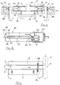
- Figure 1 shows a schematic side view of the labelling machine of the present invention in its basic components;
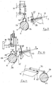
- Figure 2 shows a schematic cross-view of the labelling machine of Figure 1, corresponding to the controls for opening/closing the grasping pliers;
- Figure 3 shows a schematic side view of a second solution of the control for opening/closing the pliers;
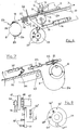
- Figure 4 shows a plan view of grasping pliers provided with small hooking pliers for the tape labels, complete of control means, applied to said pliers;
- Figure 5 shows a plan view of the adjustable guide of tape labels, according to their width;
- Figure 6 shows a schematic view of a particular section which illustrates an example of progress system of the tape label, for the wrapping-start alignment.
- Figure 7 shows an unwinding example with an excess free amount of continuous tape, with the possible presence of a supplementary tension brake;
- Figure 8 shows a side and front view of a multiple drum control for the opening adjustment of grasping pliers, for the adjustment of the inclination of the slide race of the labels and the lifting adjustment of the step-by-step progress means;
- Figures 9 and 10 shows schematically an alternative embodiment of the restraint and wrapping means of the end edge of the labels; and
- Figure 11 shows an example of adjustment and stopping control of the inclined orientation of label sliding race, operating in function of the size of the product to be labelled.
-
- The Figures show a labelling machine for products having an elongated shape and irregular surfaces, such as for instance and in particular salami, which comprises a
bearing structure 1 provided with aninclined race 2 whereon acontinuous label tape 3 can slide which unwinds from aroll 4 and aligns with aproduct 5 to be wrap-labelled, such as for instance asalami 6. -
Race 2 is substantially made up by a longitudinal channel provided with a longitudinal fixedshoulder 8 and a lower fixedguide 10. The thickness of said channel is sufficient to comprise thecontinuous label tape 3 and its width is adjustable in function of the width of the tape. Width adjustment is obtained by means of amobile plate 7, that can be positioned with respect to the longitudinal fixedshoulder 8 ofrace 2. Alid 9 closes at thetop race 2, so as to circumscribe to a sufficient minimum the space within which thecontinuous label tape 3 can move in a closely guided manner, during the unwinding. The inclination of the lowerfixed guide 10 of saidrace 2, with therelated plate 7 andlid 9, is adjustable in function of the diameter of the products to be labelled, preferably with respect to prefixed size ranges. Thefixed guide 10 is provided with anaperture 11, aligned torace 2 wherein there slides thecontinuous tape 3, in correspondence of which, from the lower part, anadvancement roll 12 appears which has a free wheel and is moved in alternated motion by alever 13 activated by apiston 14. To saidadvancement roll 12 there is coupled, from the upper part ofrace 2, a supplementarysmall wheel 15, which is supported by abracket 16 integral with asmall piston 17. Saidpiston 17, provided with a point-piece 20 oriented towardlid 9, is fixed to the end of alever 18 which has its fulcrum, at the opposite end, on the bearing structure of thefixed guide 10. Thecontinuous label tape 3 rests on the bottom ofrace 2 and slides thereon, between saidadvancement roller 12 and the smallupper wheel 15. At each operating stage of alternated advancement, the supplementary uppersmall wheel 15 lowers, pressing thelabel tape 3 against theadvancement roll 12, which is caused to rotate bypiston 14. In this way, thestart edge 19 oftape 3 is caused to advance up to its positioning in alignment with theunderlying product 5, orsalami 6, to be wrapped. In the subsequent stage,piston 17 acts with its point-piece 20 onlid 9 of thefixed guide 10,lifting bracket 16 and thesmall wheel 15 associated to the same, so thattape 3 is free again, simply resting in itsguide 2, with no hindrances to its guided sliding, except that due to the calibrated width of the race and the sliding friction in the same. At the same time, asmall friction roll 21, combined with afree wheel control 22 by means of asmall piston 23, acts on the peripheral surface ofroll 4 of acontinuous label tape 3, and unwinds it for just the length sufficient to create an excessfree amount 24 which ensures the subsequent traction stages of said tape, without the effect of the natural resistance ensuing from the inertia ofroll 4. After every unwinding, thesmall piston 23, makes a free wheel return travel for positioning thesmall roll 21, for a subsequent operating stage. - In correspondence of the
starting edge 19 of thelabel tape 3 and in cross-alignment, tworotary pliers 25 are provided which engage with the ends ofproduct 6 to be labelled and grasp it in such a way as to drag it in rotation about an axis substantially corresponding to the theoretical axis of said product. Eachpliers 25 are provided with abent panel 26 and on abent panel 26 of at least one of said pliers 25 aguide 27 is applied. Along saidguide 27 two superposedsaddles pliers 30 which align withsaid edge 19 oftape 3 and engage with it in a dragging grasp. Thelower saddle 28 is integral with the lower horizontal fixed point of thesmall pliers 30 and is coupled to the piston of a first cylinder-piston system 31 which causes it to axially slide alongguide 27. Theupper saddle 29 is coupled to the lower one 28 and moves together with it, in the same way, alongguide 27, but its front end is engaged withhinge 32 ofpliers 30 and its back end is engaged with the piston of a second cylinder-piston system 33, whose function is to cause the opening/closing of the mobile upper point, hinges in 32, of said small pliers. The piston of the second cylinder-piston system 33 is directly engaged with that of the first cylinder-piston system 31 and is therefore subject to all the axial forwards and/or backwards shifting generated by the latter. The position of saidpliers 30 is therefore near the surface ofproduct 6 and in correspondence of the tangency coupling point with thelabel tape 3, with the possibility of axial advancement/backing and opening/closing. In the subsequent coaxial rotation stage, after the grasp of thesmall pliers 30 onedge 19,tape 3 is wound onproduct 6, forming two annular vaults (generally and preferably at least two), which are perfectly aligned with each other, independently on the possible irregular configuration of the peripheral surface of the product, thanks to the unwinding oftape 3, guided bypliers 2 and not restrained by mechanical means, but unwound by the only effect of the sliding friction. For possible particular types oflabel tapes 3, however, there is provided the possibility of applying a tension brake made up by atransversal strip 34 from flexible elastic material, which rests on the front surface of thelabel tape 3, with an adjusted pressure produced by the action of apiston 35. In the last stage of wrapping oflabel 5, ahumidifying pad 36 is pushed by the action of apiston 64 in touch with the lower surface of the last length of said label, in order to humidify the glue.Pad 36 operates in opposition to an upperguide bent panel 37, so that the last edge of label, already separated fromtape 3 by means of atransversal blade 68, is engaged between them and kept in traction during the last wrapping stage: in this way, the wrapper is substantially stretched aroundproduct 6 and goes near to it to wrap it in a way as adhering as possible, while remaining perfectly aligned thanks to the lasting grasp ofpliers 30, on the one side, and the grasp ofpad 36 against thebent panel 37, on the other side. At the same time apressure pad 38 is caused to lower until it rests on the surface ofproduct 6, in correspondence of the humidified edge ofwrapper 5. Thepressure pad 38 has the function of keeping said humidified edge adhering to the underlying vault or the wrapper, to ensure the mutual adhesion. The pressing action of thepressure pad 38 is kept for all the time necessary to a one step forwards shifting of the labelled product, corresponding to the time necessary for a correct adhesion to said parts; for this reason,pad 38 is directly engaged with the bearingstructure 39 of the advancement devices. In a different embodiment, represented in Figures 9 and 10, the wrapping of the label is still guided according to what has been already described with sliding freedom, but at a given time, i.e. when the end of the label is near, or when thecutter 68 in ready to step in, or when the provided photocell detects the notch that defines the length of said label, thehumidifying pad 36 approaches the surface of said label to activate with water the glue while a braking element creates a simultaneous tension on the label whose effect, however, does not affect the correct winding, as it has already completed almost all its rotation onproduct 6. Now, the rotation is stopped andpad 38 lowers on the label and keeps it wound on the product, whilecutter 68 performs the separation cutting from thecontinuous tape 3. In this way, the end edge 19' which remains between the grasp area ofpad 38 and the cutting area ofcutter 68 does not rest against the product; this finishing is carried out by a secondaryrubberised roll 65, connected to a piston-cylinder system 66. Saidrubberised roll 65, activated by the piston-cylinder system, is caused to adhere to said edge 19' and slides on the same until it is bent onproduct 6, causing the complete gluing to the lower vault. - The stop of the rotation of the
grasp pliers 25, required by said operation, is therefore casual; at the end of labelling and during the stage of shifting of the labelled product towards the unloading, there is therefore provided a partial rotation stage of saidpliers 25, to restore their correct position of cycle start. In this way, the packings obtained are substantially perfect and homogeneous on any diameter ofproduct 6, from salami to "coppe" or other products that are in general subject to labelling. - Having concluded the stage of winding and adhesion of the wrapper,
pliers 30 release their grasp onedge 19, by effect of the release of the pressure in the second cylinder-piston system 33. Afterwards, the first cylinder-piston system 31 causespliers 30 to return backwards by unthreading it entirely from under the wrapper, without opening it, while the bent panels of thegrasp pliers 25 are caused to open to release the labelledproduct 6. The opening ofpliers 30 for the preparation of the subsequent work stage, takes place sequentially. Following the release, the labelledproducts 6 are laid onparallel side grids 40 provided with sequential V-shaped spaces wherein the end parts of said products rest.Side grids 49 are supported together and are free to slide with alternate movement for- and backwards on a bench-saddle 41 which, in its turn, has an alternate lifting and lowering motion. On each release,grids 40 are adequately lifted to collect the unloaded products. Figure 1 shows an embodiment, solely given by way of example, of said movement and control means. They comprise cylinder-piston systems 42 which, throughlevers 43, having their fulcrum in 44, cause the lifting of thebench saddle 41, theside grids 40 associated to the same and thepressure pad 38, which acts on the just manufacturedwrapper 5. - At the same time, the same action engages, in the back part of the machine, the collection of
other products 6 to be labelled from thefeed grids 45. Other cylinder-piston systems 46, connected to theside grids 40 through levers, cause said raisedside grids 40 to advance by a step, causing the already treated product to go away fromrace 2 and to bring in the same position another product to be labelled, which is grasped bypliers 25. The lowering ofsaddle 41 caused by the cylinder-piston system 42 and the backwards motion of theside grids 40 caused by the cylinder-piston system 46, restore the operating conditions for the subsequent feed and unloading stages. - Examples of opening/closing means of the
grasp pliers 25 are represented in Figures 2 and 3.Pliers 25, aligned with one another in opposition to grasp the opposite ends ofproducts 6, are engaged with back pins that rotate insupport 47 and which receive the motion throughchain gearing systems 48 or the like, coupled to a ratio-motor 49. Coaxially with said pins drivebars 50 are provided which, throughlevers 51 withelastic fulcrum 52 and cylinder-piston systems levers 55, with ensuing opening and/or closing of the grasp bentpanels 26. Preferably, fulcra 52 are constituted by small rolls which are free to oscillate on the surface ofsupports 56, to make up for possible axial shifting. Said rolls are kept in touch withsupports 56 byelastic means 57. The cylinder-piston control systems first ones 53, thrusters, and thesecond one 54, pressure adjusters, to prevent possible lacerations of the peripheral surfaces ofproducts 6. Alternatively, and more simply, the same opening/closing controls of the pliers may be realised by cylinder-piston systems 58 applied directly and coaxially to the control bars 50 (see Fig. 3). - Based on the type of product to be labelled, or based on its more or less regular diameter dimension around which the labels must be wrapped, the machine is provided with adjustment means that allow an adequate alignment of the
continuous label tape 3 with said product. In particular, and according to an elementary and economical solution, said means are constituted by simple end-of-travel means, such as, for instance, adjustment screws applied to anonly drum 59. Saiddrum 59 is placed near one of the control end of thegrasp pliers 25 and allows the adjustment of the inclined orientation ofrace 2, in function of the tangency point of thelabel tape 3 with the product diameter, and an adjustment of the opening/closing ofgrasp pliers 25 and the raising/lowering of the bench-saddle 41, with therelated side grids 40, always in function of the diameter of the product being treated. Obviously, said devices are adopted within defined, circumscribed and preferred use fields. Ondrum 59, there are provided a first set of axial end-of-travels 60', a second set of radial end-of-travels 60'', and at least a third type of radial end-of-travels 60''' for raising thebench saddle 41. The axial end-of-travels 61', selected withdisc 61 stops the closing travel ofpliers 25 in function of the diameter of the product they must grasp. The radial end-of-travels 60'', in function of the same product diameter, form thefront rest 62, suitably inclined, of the fixedguide 10 withrace 2, which rotates around itsback fulcrum 63. The third type of end-of-travel 60''' allows to adjust the raising of thebench saddle 41 with therelated side grids 40. - According to an alternative solution, given by way of non limiting example, the inclined orientation of
guide 10 that feeds thecontinuous label tape 3, the opening/closing ofgrasp pliers 25 and the raising/lowering of the transport means 40 may be realised without the utilisation of saiddrum 59. In rest conditions, said devices are positioned in the maximum opening condition, or they are positioned as if they were to label the products having the maximum diameter. Once the approx. average diameter ofproducts 6 to be labelled is known, the various adjustments are performed. The raising/lowering of the transport means 40 is made through a proximity switch (not shown), located on the control board of the machine, through which it is possible to select, among defined positions, the one corresponding to the travel desired. To each position a given fixed striker corresponds that is located on at least one of the slide axes 69 of thebench saddle 41. By means of variable position targets provided with a continuous board adjuster, any desired travel comprised within the use field of the machine may be selected. In any case, the choice of the travels should be made taking into account the fact that the products to be labelled must assume a loading position that is almost axed with theopen grasp pliers 25. The raising/lowering of thebench saddle 41 is generated, as described, bypistons 42 controlled by closed centre electro-valves, - The
bent panels 26 ofpliers 25 close on the products to be labelled 6 according to the same principle described above, by means of coupledpistons guide 10 which feeds thecontinuous label tape 3 and thegrasp pliers 25 are at the maximum opening, but in such a position that thestart edge 19 of the label is aligned, with a correct feed, withpliers 30. On the arrival of the product to be labelled 6,pliers 30 engage withedge 19 of thecontinuous label tape 3,pliers 25 close theirbent panels 26 around said product and guide 10feeding tape 3 rotates, inclining, until it steps near the external periphery of said product, controlled by aproximity micro-switch 67 to which alever 70 is coupled which lies against one of saidbent panels 26 already closed in restraining position. In this way, the smaller the diameter of the product the more the bent panels close to grasp it and, consequently, themore guide 10 inclines and can therefore be always correctly aligned withpliers 30. The rotation ofguide 10 feeding thecontinuous tape 3, takes place around its back fulcrum 63 and is produced by means of at least a piston, piloted by at least a closed centre electro-valve. At the end of the labelling, feedguide 10 raises again, thebent panels 26 open again entirely, thebench saddle 41 raises and theside grids 40 collect and shift towards the unloading point the labelled product and align in the machine another product to be labelled. - Even though the present invention has been described and illustrated according to embodiments solely given by way of non limiting example, it is obvious that many modifications and changes in the structure, the components, the types of controls adopted, the orientations and the positions of the operating units, the configuration of details, the technical and functional devices may be introduced by those skilled in the art in the light of the above teaching and description. It is therefore understood that the present invention intends to embrace all the changes and modifications that fall within the spirit of the present invention and the protection scope of the appended claims.
Claims (13)
- A labelling machine for products having an irregular elongated shape, comprising: a) guided and aligned sliding means (2) for continuous tape tackified-labels (3), provided with dimensional adjustment (7) and orientation (60'', 62, 67, 70) devices and aligned positioning means (12, 15); b) motor-driven, lateral, opposed and coaxial rotary means (25) for grasping the products (6) to be labelled, provided with devices (30) for hooking the end edge (19) of tape labels (3), with drawing and orthogonal guided wrapping of the same with grasping adjustments/positioning means (60', 61, 53, 54) and opening/closing means (30, 31, 32, 50, 55); and c) means for the alternate lifting (41) and step-by-step advancement (40) of the products to be treated or already treated (6), with the related devices for the adjustment of the specified shifting travels.
- The labelling machine according to claim 1, characterised in that the guided and aligned sliding means of the tape labels (3) are constituted by a lower fixed guide (10), whose inclination is adjustable in function of the diameter of products (6) to be labelled, on which a longitudinal race or channel (2) is formed that comprises a fixed shoulder (8), an opposite mobile shoulder (7) and an opening-tiltable upper lid (9), said race (2) forming a circumscribed channel inside which the continuous label tape (3) slides in perfect alignment under the drawing action of hooking and drawing means (30) present on at least one of the motor-driven rotary means (25), for grasping products (6) to be labelled.
- The labelling machine according to claims 1 or 2, characterised in that the aligned positioning means of the continuous label tape (3) to the tangency point of its starting edge (19) with product (6) to be labelled, comprise:an aperture (11) obtained on the fixed guide (10) and aligned with the slide race (2);a free wheel advancement roll (12), which aligns through said aperture with the slide race (2), said advancement roll (12) being provided with means (13, 14 for its alternate rotation movement; andan upper small wheel (15) located on the same race (2) and aligned with said advancement roll (12), said upper small wheel (15) being connected to the bearing structure of the fixed guide (10) through a lever (18), a bracket (16) and a small piston (17) provided with a point-piece (20) operating on lid (9) of said fixed guide (10) for raising or lowering said upper wheel (15) in touch with or detached from the advancement roll (12).
- The labelling machine according to any of the preceding claims, characterised in that the rotary means for grasping products (6) to be labelled are constituted by two opposite rotary pliers (25) comprising each bent panels (26) closing/opening activated by a couple of thrusting (53) and pressure adjusting (54) serially arranged cylinder-piston systems; said cylinder-piston systems transmitting an axial translation motion to small levers (55) activating said bent panels (26).
- The labelling machine according to any of the preceding claims 1-3, characterised in that the rotary means for grasping products (6) to be labelled are constituted by two opposite rotary pliers (25) comprising each bent panels (26) closing/opening activated by cylinder-piston systems (58) directly connected to the activating levers (55) of said bent panels (26).
- The labelling machine according to any of the preceding claims, characterised in that the devices for hooking the aligned end edge (19) of the continuous label tape (3) comprise at least grasp pliers (30) applied to the open end of at least a bent panel (27) of said pliers (25) in a position substantially tangent to a peripheral engagement point of the products to be labelled (6) with said pliers; said pliers comprising a lower fixed point integral with a first saddle (28) and an upper mobile point, opening/closing engaged with a hinge (32) integral with a second saddle (29), superposed to the first one (28) and axially slidable with it along a common guide (27) applied to the back of said bent panel; said saddles (28, 28), being axially moved by a piston (31) to which a second piston (33) for opening/closing the mobile point of pliers (30) is coupled.
- The labelling machine according to any of the preceding claims, characterised in that a humidifying pad (36) adheres to and humidify the lower tackified part of the label, separate from the continuous tape, operating on the same a controlled pressure, in opposition to a overlaying guide bent panel (37).
- The labelling machine according to claim 7, characterised in that, in the end part of wrapper (5), a pressing pad (38), engaged with the bearing structure (39) of the advancement devices, keeps in adherent position the humidified edge, with the underlying part of the wrapper already wound on product (6).
- The labelling machine according to any of the preceding claims, characterised in that it comprises means for the alternate lifting and step-by-step advancement comprising a bench saddle (41) which moves upwards/downwards in a controlled manner by means of the activating pistons (42) that act tilting lever systems (43), and side grids (40) with serial V-shaped spaces wherein the ends of products (6) rest, provided with axial forwards/backwards movement.
- The labelling machine according to any of the preceding claims, characterised in that the means for adjusting the various positions are located on one only drum (59) which is located near one of the control ends of pliers (25) and comprises:a plurality of axial end-of-travels (60') adjustable to different lengths in function of the diameters of products (6) and the corresponding opening/closing of pliers (25) said axial end-of-travels (60') being coupled to a disk (61) coaxially engaged with at least one of the ends of said pliers;a plurality of radial end-of-travels (60') adjustable to different lengths in function of the diameters of products (6) and the corresponding inclination which the fixed race (10) must assume to constitute the tangency point of the end edges (19) of said products; andat least a radial end-of-travel (60''') adjustable to different lengths in function of the diameters of products (6) and the corresponding upwards/downwards travel of the bench saddle (41).
- The labelling machine according to claims 1 and 2, characterised in that the means for adjusting the various positions include:means for closing the bent panels of said grasp pliers (25) with grasp and pressure adjustment by serially combined pistons (53, 54);means for adjusting the upwards/downwards travels of the bench saddle (41) with the related parallel grids (40), constituted by a finished or continuous position switch, located on the control board, coupled to fixed or target strikers, applied to at least one of the slide axes (69) of said saddle (41), said upwards/downwards motions being due to the action of pistons driven by closed centre pistons; andmeans for adjusting the inclined position of guide (10), the alignment of the unloading channel (2) of the continuous label tape (3) with the products to be labelled engaged in the grasp pliers (25) constituted by at least a proximity microswitch (67) combined and activated by means of a lever (70) engaged with the same guide (10) which during the lowering rotation, gets in touch and engages with one of said bent panels (26) already closed in grasp positions, said rotation of guide (10) being due to the movement produced by a piston which is piloted by at least a closed centre electro-valve for stopping in the positions desired.
- The labelling machine according to any of the preceding claims, characterised in that it comprises an auxiliary brake of the label continuous tape (3), comprising a transversal strip from flexible elastic material (34) resting on the upper surface of said tape with a pressure adjusted by a cylinder-piston system (35).
- The labelling machine according to any of the preceding claims, characterised in that the roll (4) of the label continuous tape (3) is provided with a free length unwinder (24) of said tape, comprising a friction roll (21) combined with a8 free wheel control (22) activated by a piston (23).
Applications Claiming Priority (2)
| Application Number | Priority Date | Filing Date | Title |
|---|---|---|---|
| ITRE970072 | 1997-10-10 | ||
| IT97RE000072A IT1297986B1 (en) | 1997-10-10 | 1997-10-10 | LABELING MACHINE FOR IRREGULAR ELONGATED FORM PRODUCTS |
Publications (2)
| Publication Number | Publication Date |
|---|---|
| EP0911264A1 true EP0911264A1 (en) | 1999-04-28 |
| EP0911264B1 EP0911264B1 (en) | 2002-02-06 |
Family
ID=11399112
Family Applications (1)
| Application Number | Title | Priority Date | Filing Date |
|---|---|---|---|
| EP98118764A Expired - Lifetime EP0911264B1 (en) | 1997-10-10 | 1998-10-05 | Labelling machine for products having an irregular elongated shape like sausages |
Country Status (4)
| Country | Link |
|---|---|
| EP (1) | EP0911264B1 (en) |
| AT (1) | ATE212932T1 (en) |
| DE (1) | DE69803735D1 (en) |
| IT (1) | IT1297986B1 (en) |
Cited By (1)
| Publication number | Priority date | Publication date | Assignee | Title |
|---|---|---|---|---|
| CN113665931A (en) * | 2021-08-27 | 2021-11-19 | 中国人民解放军陆军军医大学第一附属医院 | Automatic sign indicating number device that pastes of heparin tube |
Citations (4)
| Publication number | Priority date | Publication date | Assignee | Title |
|---|---|---|---|---|
| FR2443387A1 (en) * | 1978-12-08 | 1980-07-04 | Ditzel Gmbh Gebr | Wall paper roll wrapping and labelling system - has transport belts with holders and gripping and turning mechanism at label feed |
| EP0129489A1 (en) * | 1983-06-14 | 1984-12-27 | Claude Dard | Labelling machine for cylindrical products, especially sausages |
| EP0161585A1 (en) * | 1984-05-09 | 1985-11-21 | Gianfranco Cecchi | Process and apparatus for applying labels |
| FR2600306A1 (en) * | 1986-06-19 | 1987-12-24 | Vilanova Alzamora Manuel | Improvements to devices for applying labels, for pieces of sausage or similar preparations |
-
1997
- 1997-10-10 IT IT97RE000072A patent/IT1297986B1/en active IP Right Grant
-
1998
- 1998-10-05 DE DE69803735T patent/DE69803735D1/en not_active Expired - Lifetime
- 1998-10-05 AT AT98118764T patent/ATE212932T1/en not_active IP Right Cessation
- 1998-10-05 EP EP98118764A patent/EP0911264B1/en not_active Expired - Lifetime
Patent Citations (4)
| Publication number | Priority date | Publication date | Assignee | Title |
|---|---|---|---|---|
| FR2443387A1 (en) * | 1978-12-08 | 1980-07-04 | Ditzel Gmbh Gebr | Wall paper roll wrapping and labelling system - has transport belts with holders and gripping and turning mechanism at label feed |
| EP0129489A1 (en) * | 1983-06-14 | 1984-12-27 | Claude Dard | Labelling machine for cylindrical products, especially sausages |
| EP0161585A1 (en) * | 1984-05-09 | 1985-11-21 | Gianfranco Cecchi | Process and apparatus for applying labels |
| FR2600306A1 (en) * | 1986-06-19 | 1987-12-24 | Vilanova Alzamora Manuel | Improvements to devices for applying labels, for pieces of sausage or similar preparations |
Cited By (2)
| Publication number | Priority date | Publication date | Assignee | Title |
|---|---|---|---|---|
| CN113665931A (en) * | 2021-08-27 | 2021-11-19 | 中国人民解放军陆军军医大学第一附属医院 | Automatic sign indicating number device that pastes of heparin tube |
| CN113665931B (en) * | 2021-08-27 | 2022-11-08 | 中国人民解放军陆军军医大学第一附属医院 | Automatic sign indicating number device that pastes of heparin tube |
Also Published As
| Publication number | Publication date |
|---|---|
| ITRE970072A0 (en) | 1997-10-10 |
| ITRE970072A1 (en) | 1999-04-10 |
| DE69803735D1 (en) | 2002-03-21 |
| EP0911264B1 (en) | 2002-02-06 |
| ATE212932T1 (en) | 2002-02-15 |
| IT1297986B1 (en) | 1999-12-20 |
Similar Documents
| Publication | Publication Date | Title |
|---|---|---|
| US3765991A (en) | Labeling apparatus | |
| US5046675A (en) | System and method for cutting and spooling a web of paper | |
| US3052073A (en) | Strip rolling and wrapping machine | |
| US4162025A (en) | Apparatus for unreeling valved sacks which are reeled in overlapping formation | |
| EP0174066B1 (en) | Winding apparatus | |
| US3290861A (en) | Roll wrapper | |
| US4850177A (en) | Stretch bundler | |
| MXPA02002177A (en) | Apparatus and a method for rolling compressible sheet material. | |
| EP0911264B1 (en) | Labelling machine for products having an irregular elongated shape like sausages | |
| US6629662B2 (en) | Method and apparatus for rolling carpet | |
| US5256232A (en) | Apparatus and method for winding strips of web material onto spools | |
| AU660791B2 (en) | Apparatus for rolling up a printed product and winding a wrapping around the roll | |
| CA2046605C (en) | System and method for cutting and spooling a web of paper | |
| US3968622A (en) | Roll packaging apparatus | |
| US6837156B2 (en) | Twist tie feed device | |
| CN114104800A (en) | Strip winding robot | |
| US5507450A (en) | Apparatus for the winding of continuous webs | |
| US4626314A (en) | Labeling machine attachment for stack exiting of round labeled objects | |
| JPH021726B2 (en) | ||
| EP0132862A1 (en) | A device for identification of cheese by applying printed matter | |
| US4936073A (en) | Stretch bundler | |
| EP4086182A1 (en) | Machine for stabilising palletised loads with reel change system | |
| US3236469A (en) | Tape winding device and method | |
| US4693774A (en) | Method of labeling using a semi-automatic labeling machine | |
| US20040250510A1 (en) | Apparatus and method for dispensing wrapper and wrapping products |
Legal Events
| Date | Code | Title | Description |
|---|---|---|---|
| PUAI | Public reference made under article 153(3) epc to a published international application that has entered the european phase |
Free format text: ORIGINAL CODE: 0009012 |
|
| AK | Designated contracting states |
Kind code of ref document: A1 Designated state(s): AT BE CH DE DK ES FI FR GB GR IE LI LU MC NL PT SE |
|
| AX | Request for extension of the european patent |
Free format text: AL;LT;LV;MK;RO;SI |
|
| 17P | Request for examination filed |
Effective date: 19990920 |
|
| AKX | Designation fees paid |
Free format text: AT BE CH DE DK ES FI FR GB GR IE LI LU MC NL PT SE |
|
| 17Q | First examination report despatched |
Effective date: 20000911 |
|
| GRAG | Despatch of communication of intention to grant |
Free format text: ORIGINAL CODE: EPIDOS AGRA |
|
| GRAG | Despatch of communication of intention to grant |
Free format text: ORIGINAL CODE: EPIDOS AGRA |
|
| GRAH | Despatch of communication of intention to grant a patent |
Free format text: ORIGINAL CODE: EPIDOS IGRA |
|
| GRAH | Despatch of communication of intention to grant a patent |
Free format text: ORIGINAL CODE: EPIDOS IGRA |
|
| GRAA | (expected) grant |
Free format text: ORIGINAL CODE: 0009210 |
|
| REG | Reference to a national code |
Ref country code: GB Ref legal event code: IF02 |
|
| AK | Designated contracting states |
Kind code of ref document: B1 Designated state(s): AT BE CH DE DK ES FI FR GB GR IE LI LU MC NL PT SE |
|
| PG25 | Lapsed in a contracting state [announced via postgrant information from national office to epo] |
Ref country code: NL Free format text: LAPSE BECAUSE OF FAILURE TO SUBMIT A TRANSLATION OF THE DESCRIPTION OR TO PAY THE FEE WITHIN THE PRESCRIBED TIME-LIMIT Effective date: 20020206 Ref country code: LI Free format text: LAPSE BECAUSE OF FAILURE TO SUBMIT A TRANSLATION OF THE DESCRIPTION OR TO PAY THE FEE WITHIN THE PRESCRIBED TIME-LIMIT Effective date: 20020206 Ref country code: GR Free format text: LAPSE BECAUSE OF FAILURE TO SUBMIT A TRANSLATION OF THE DESCRIPTION OR TO PAY THE FEE WITHIN THE PRESCRIBED TIME-LIMIT Effective date: 20020206 Ref country code: FR Free format text: LAPSE BECAUSE OF FAILURE TO SUBMIT A TRANSLATION OF THE DESCRIPTION OR TO PAY THE FEE WITHIN THE PRESCRIBED TIME-LIMIT Effective date: 20020206 Ref country code: FI Free format text: LAPSE BECAUSE OF FAILURE TO SUBMIT A TRANSLATION OF THE DESCRIPTION OR TO PAY THE FEE WITHIN THE PRESCRIBED TIME-LIMIT Effective date: 20020206 Ref country code: CH Free format text: LAPSE BECAUSE OF FAILURE TO SUBMIT A TRANSLATION OF THE DESCRIPTION OR TO PAY THE FEE WITHIN THE PRESCRIBED TIME-LIMIT Effective date: 20020206 Ref country code: BE Free format text: LAPSE BECAUSE OF FAILURE TO SUBMIT A TRANSLATION OF THE DESCRIPTION OR TO PAY THE FEE WITHIN THE PRESCRIBED TIME-LIMIT Effective date: 20020206 Ref country code: AT Free format text: LAPSE BECAUSE OF FAILURE TO SUBMIT A TRANSLATION OF THE DESCRIPTION OR TO PAY THE FEE WITHIN THE PRESCRIBED TIME-LIMIT Effective date: 20020206 |
|
| REF | Corresponds to: |
Ref document number: 212932 Country of ref document: AT Date of ref document: 20020215 Kind code of ref document: T |
|
| REG | Reference to a national code |
Ref country code: CH Ref legal event code: EP |
|
| REF | Corresponds to: |
Ref document number: 69803735 Country of ref document: DE Date of ref document: 20020321 |
|
| PG25 | Lapsed in a contracting state [announced via postgrant information from national office to epo] |
Ref country code: SE Free format text: LAPSE BECAUSE OF FAILURE TO SUBMIT A TRANSLATION OF THE DESCRIPTION OR TO PAY THE FEE WITHIN THE PRESCRIBED TIME-LIMIT Effective date: 20020506 Ref country code: PT Free format text: LAPSE BECAUSE OF FAILURE TO SUBMIT A TRANSLATION OF THE DESCRIPTION OR TO PAY THE FEE WITHIN THE PRESCRIBED TIME-LIMIT Effective date: 20020506 Ref country code: DK Free format text: LAPSE BECAUSE OF FAILURE TO SUBMIT A TRANSLATION OF THE DESCRIPTION OR TO PAY THE FEE WITHIN THE PRESCRIBED TIME-LIMIT Effective date: 20020506 |
|
| PG25 | Lapsed in a contracting state [announced via postgrant information from national office to epo] |
Ref country code: DE Free format text: LAPSE BECAUSE OF FAILURE TO SUBMIT A TRANSLATION OF THE DESCRIPTION OR TO PAY THE FEE WITHIN THE PRESCRIBED TIME-LIMIT Effective date: 20020507 |
|
| NLV1 | Nl: lapsed or annulled due to failure to fulfill the requirements of art. 29p and 29m of the patents act | ||
| REG | Reference to a national code |
Ref country code: CH Ref legal event code: PL |
|
| PG25 | Lapsed in a contracting state [announced via postgrant information from national office to epo] |
Ref country code: ES Free format text: LAPSE BECAUSE OF FAILURE TO SUBMIT A TRANSLATION OF THE DESCRIPTION OR TO PAY THE FEE WITHIN THE PRESCRIBED TIME-LIMIT Effective date: 20020829 |
|
| PG25 | Lapsed in a contracting state [announced via postgrant information from national office to epo] |
Ref country code: LU Free format text: LAPSE BECAUSE OF NON-PAYMENT OF DUE FEES Effective date: 20021005 Ref country code: GB Free format text: LAPSE BECAUSE OF NON-PAYMENT OF DUE FEES Effective date: 20021005 |
|
| PG25 | Lapsed in a contracting state [announced via postgrant information from national office to epo] |
Ref country code: IE Free format text: LAPSE BECAUSE OF NON-PAYMENT OF DUE FEES Effective date: 20021007 |
|
| EN | Fr: translation not filed | ||
| PLBE | No opposition filed within time limit |
Free format text: ORIGINAL CODE: 0009261 |
|
| STAA | Information on the status of an ep patent application or granted ep patent |
Free format text: STATUS: NO OPPOSITION FILED WITHIN TIME LIMIT |
|
| 26N | No opposition filed |
Effective date: 20021107 |
|
| PG25 | Lapsed in a contracting state [announced via postgrant information from national office to epo] |
Ref country code: MC Free format text: LAPSE BECAUSE OF NON-PAYMENT OF DUE FEES Effective date: 20030501 |
|
| GBPC | Gb: european patent ceased through non-payment of renewal fee |
Effective date: 20021005 |
|
| REG | Reference to a national code |
Ref country code: IE Ref legal event code: MM4A |