EP0909977A1 - Method and apparatus for copying a transparent original onto light-sensitive material - Google Patents
Method and apparatus for copying a transparent original onto light-sensitive material Download PDFInfo
- Publication number
- EP0909977A1 EP0909977A1 EP98117310A EP98117310A EP0909977A1 EP 0909977 A1 EP0909977 A1 EP 0909977A1 EP 98117310 A EP98117310 A EP 98117310A EP 98117310 A EP98117310 A EP 98117310A EP 0909977 A1 EP0909977 A1 EP 0909977A1
- Authority
- EP
- European Patent Office
- Prior art keywords
- image
- points
- generated
- raster
- raster image
- Prior art date
- Legal status (The legal status is an assumption and is not a legal conclusion. Google has not performed a legal analysis and makes no representation as to the accuracy of the status listed.)
- Granted
Links
- 238000000034 method Methods 0.000 title claims abstract description 15
- 239000000463 material Substances 0.000 title claims description 5
- 238000009792 diffusion process Methods 0.000 claims abstract description 8
- 238000003384 imaging method Methods 0.000 claims 1
- 238000005286 illumination Methods 0.000 abstract 2
- 230000009897 systematic effect Effects 0.000 description 5
- 238000012216 screening Methods 0.000 description 3
- PEDCQBHIVMGVHV-UHFFFAOYSA-N Glycerine Chemical compound OCC(O)CO PEDCQBHIVMGVHV-UHFFFAOYSA-N 0.000 description 2
- 238000004364 calculation method Methods 0.000 description 2
- 239000004973 liquid crystal related substance Substances 0.000 description 2
- 238000013139 quantization Methods 0.000 description 2
- 206010029412 Nightmare Diseases 0.000 description 1
- 239000000919 ceramic Substances 0.000 description 1
- 230000000739 chaotic effect Effects 0.000 description 1
- 230000006835 compression Effects 0.000 description 1
- 238000007906 compression Methods 0.000 description 1
- 230000000694 effects Effects 0.000 description 1
- 230000003760 hair shine Effects 0.000 description 1
- 230000009191 jumping Effects 0.000 description 1
- 239000007788 liquid Substances 0.000 description 1
- 230000000873 masking effect Effects 0.000 description 1
Images


Classifications
-
- G—PHYSICS
- G03—PHOTOGRAPHY; CINEMATOGRAPHY; ANALOGOUS TECHNIQUES USING WAVES OTHER THAN OPTICAL WAVES; ELECTROGRAPHY; HOLOGRAPHY
- G03B—APPARATUS OR ARRANGEMENTS FOR TAKING PHOTOGRAPHS OR FOR PROJECTING OR VIEWING THEM; APPARATUS OR ARRANGEMENTS EMPLOYING ANALOGOUS TECHNIQUES USING WAVES OTHER THAN OPTICAL WAVES; ACCESSORIES THEREFOR
- G03B27/00—Photographic printing apparatus
- G03B27/72—Controlling or varying light intensity, spectral composition, or exposure time in photographic printing apparatus
- G03B27/725—Optical projection devices wherein the contrast is controlled electrically (e.g. cathode ray tube masking)
-
- H—ELECTRICITY
- H04—ELECTRIC COMMUNICATION TECHNIQUE
- H04N—PICTORIAL COMMUNICATION, e.g. TELEVISION
- H04N1/00—Scanning, transmission or reproduction of documents or the like, e.g. facsimile transmission; Details thereof
- H04N1/40—Picture signal circuits
- H04N1/405—Halftoning, i.e. converting the picture signal of a continuous-tone original into a corresponding signal showing only two levels
- H04N1/4051—Halftoning, i.e. converting the picture signal of a continuous-tone original into a corresponding signal showing only two levels producing a dispersed dots halftone pattern, the dots having substantially the same size
- H04N1/4052—Halftoning, i.e. converting the picture signal of a continuous-tone original into a corresponding signal showing only two levels producing a dispersed dots halftone pattern, the dots having substantially the same size by error diffusion, i.e. transferring the binarising error to neighbouring dot decisions
Definitions
- the invention is based on a method and a device for copying a transparent template on light-sensitive material according to the generic term of claim 1 and claim 8, respectively.
- Gray values can also be displayed on the LCD. Becomes an LCD with a ferroelectric If liquid crystal is used, the gray values to be displayed must be rasterized because the individual points of such an LCD are only light or dark are switchable. In DE PS 43 08 864 there is therefore a subdivision of the LCD proposed in fixed areas. These areas called macropixels can be divided into six individually controllable pixels, their areas behave like 1: 2: 4: 8: 16: 32. Through different combinations The control of these pixels can be macropixels in 64 brightness levels produce.
- an LCD that is used to mask a transparent template is used, driven according to a raster image, that the gray values to be displayed without systematic structures be generated.
- Systematic structures such as always the same Macropixel of the above-mentioned DE-PS 43 08 864 to illustrate the Grayscale values, can also be overlaid with regular structures, like edges in the copy template, a blurring of these edges in the copy cause.
- an output image from the density values of the scanned original with predetermined Local and grayscale resolution determined by a computer. This The original image is rasterized using the error diffusion method.
- the specified path can be in a LUT (look-up table). This will make the individual points only one order is assigned, and the calculation of each next point during rasterization is omitted.
- LUT look-up table
- the high-resolution scanning of the original to generate the original image is very time consuming. It is therefore advantageous to have the template in a set Scan resolution that is chosen lower than the desired resolution the mask. This low resolution must then be done in an intermediate step increase. This can be done by having everyone scanned Density value is saved several times. However, it is more advantageous that To increase the resolution by realizing that the memory address of a every density value always a defined number of addresses in the raster image is assigned. If the resolution is to be quadrupled, for example an address in the density value memory, in which the density values of the to be screened scanned image of lower resolution are stored, always sixteen addresses assigned in the grid memory.
- a transparent document 1 is passed through a scanning station 2.
- the image is point by point over the light source 3, the lens 4 and the slit diaphragm 5 scanned.
- the light beam that has passed through the film is transmitted through the lens 6 bundled again and broken down into its color components by beam splitter 7.
- density values for a mask are determined from this, which are based on the raster hardware 9 are transmitted.
- density values are converted into an inverse raster image converted, which is determined using the error diffusion method becomes.
- the next point to be rasterized is selected along the Hilber path, which is specified in a LUT 19.
- Corresponding the raster image thus generated are 10 individual points of the Light converter 11 driven to generate the mask.
- a light converter are suitable - as indicated in FIG. 1 - for example all digital light valves, i.e. liquid crystals such as FLCDs or ceramics such as PLZTs, which can be Light source 12 shines through a condenser 13 with a color filter arrangement 14 become. Likewise, LEDs can be provided which make the light source superfluous do. Furthermore, a lens 17 and a second lens arrangement 18 provided in front of the paper in the beam path.
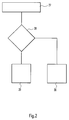
- Fig. 2 shows a flow chart to illustrate the nightmare of the screening of the Source image.
- the numerical size of the density value of a point on the The path that is taken from the density value memory is with the error of Quantization of the previous point in step 27 added to a result.
- decision step 28 the result is compared with a raster threshold. If the result is above the raster threshold, the corresponding one becomes Screen dot set to 1 in step 29. This in turn results from this an error in quantizing the next point in step 27 is taken into account accordingly. If the result from step 27 is below of the raster threshold, the corresponding raster point in step 30 assigned 0. Here too the resulting error in the Quantization of the next point in step 27 is taken into account.
- Fig. 3 shows a Hilbert path through a grid with 16 x 16 points.
- FIG. 5 shows examples of a mask rasterized in different ways.
- the mask shown on the left was the template according to that in the DE 43 08 864 C2 proposed methods screened. It turns out that the sharp edges of a template in the mask are blurred, so that on a so masked copy of the template expected fraying on the edges are.
- the mask on the right side which by means of the The inventive method was rasterized, sharp edges, too can be reproduced sharply on the masked copy.
Landscapes
- Physics & Mathematics (AREA)
- Spectroscopy & Molecular Physics (AREA)
- General Physics & Mathematics (AREA)
- Engineering & Computer Science (AREA)
- Multimedia (AREA)
- Signal Processing (AREA)
- Image Processing (AREA)
- Printing Methods (AREA)
Abstract
Description
Die Erfindung geht aus von einem Verfahren und einer Vorrichtung zum Kopieren
einer transparenten Vorlage auf lichtempfindliches Material nach dem Oberbegriff
von Anspruch 1 bzw. Anspruch 8.The invention is based on a method and a device for copying
a transparent template on light-sensitive material according to the generic term
of claim 1 and
Bei fotografischen Aufnahmen, die in einzelnen Bereichen große Helligkeitsunterschiede beinhalten, sind oftmals die erstellten Kopien in den hellen Bereichen überbelichtet oder aber in den dunkleren Bereichen unterbelichtet. Dadurch werden Einzelheiten oder feinere Strukturen auf dem Papierbild sehr schlecht oder gar nicht mehr erkennbar wiedergegeben.In photographic recordings, there are large differences in brightness in individual areas often include the copies made in the light areas overexposed or underexposed in the darker areas. Thereby details or finer structures on the paper picture become very bad or no longer recognizable.
In der DE PS 28 20 965 ist eine Kopiervorrichtung beschrieben, bei der die Beleuchtungseinrichtung
für den fotografischen Film durch eine Lichtquelle und ein
Liquid Cristal Display (LCD) gebildet wird. Über eine elektrische Ansteuerung
wird auf diesem Display eine Schwarzweiß-Negativmaske des Originals erzeugt.
Wird nun die Papierbelichtung durch diese Maske und das Original durchgeführt,
so ergibt sich dadurch eine erwünschte Dichtekompression. In DE
Um eine entsprechende Schwarzweiß-Maske erzeugen zu können, müssen mit dem LCD auch Grauwerte darstellbar sein. Wird ein LCD mit einem ferroelektrischen Flüssigkristall verwendet, so müssen die darzustellenden Grauwerte aufgerastert werden, da die Einzelpunkte eines solchen LCDs nur hell oder dunkel schaltbar sind. In der DE PS 43 08 864 wird deshalb eine Unterteilung des LCD in feste Bereiche vorgeschlagen. Diese Bereiche, die als Makropixel bezeichnet werden können, sind in sechs einzeln ansteuerbare Pixel aufgeteilt, deren Flächen sich wie 1:2:4:8:16:32 verhalten. Durch unterschiedliche Kombinationen bei der Ansteuerung dieser Pixel lassen sich so Makropixel in 64 Helligkeitsstufen erzeugen.To be able to create a corresponding black and white mask, you must use Gray values can also be displayed on the LCD. Becomes an LCD with a ferroelectric If liquid crystal is used, the gray values to be displayed must be rasterized because the individual points of such an LCD are only light or dark are switchable. In DE PS 43 08 864 there is therefore a subdivision of the LCD proposed in fixed areas. These areas called macropixels can be divided into six individually controllable pixels, their areas behave like 1: 2: 4: 8: 16: 32. Through different combinations The control of these pixels can be macropixels in 64 brightness levels produce.
Es hat sich herausgestellt, daß mit einer so erzeugten Maske fotografische Aufnahmen mit vielen feingezeichneten Details ausgezeichnet kopiert werden können, ohne daß beispielsweise Moiré-Effekte, also gewisse Schwebungen bei der Wiedergabe feiner Strukturen zu beobachten sind. Beim Kopieren von Bildern mit großen, sehr gleichmäßigen Flächen treten dagegen oftmals in der Kopie Strukturen auf, die in der transparenten Vorlage nicht vorhanden sind.It has been found that photographic recordings with a mask produced in this way can be copied excellently with many finely drawn details, without, for example, moiré effects, i.e. certain beats in the Reproduction of fine structures can be observed. When copying pictures with large, very even surfaces, however, often occur in the copy Structures that are not present in the transparent template.
Es hat sich auch gezeigt, daß an sich scharfe Kanten in der transparenten Vorlage durch das Maskieren so verunschärft werden, daß auf dem Papierbild ungleichmäßige Ausfransungen solcher Kanten zu beobachten sind.It has also been shown that there are sharp edges in the transparent template be so blurred by masking that uneven on the paper image Fraying of such edges can be observed.
Es war daher die Aufgabe der Erfindung, beispielsweise ein LCD zur Erzeugung einer Maske mit vorgegebener Auflösung so anzusteuern, daß große gleichmäßige Flächen in einer transparenten Vorlage auch in der Kopie gleichmäßig und/oder scharfe Kanten solcher Flächen nicht ausgefranst abgebildet werden.It was therefore the object of the invention, for example an LCD for generation a mask with a predetermined resolution so that large uniform Areas in a transparent template even in the copy and / or sharp edges of such surfaces are not frayed.
Gelöst wird die Aufgabe durch ein Verfahren mit den kennzeichnenden Merkmalen
von Anspruch 1 und eine Vorrichtung mit den kennzeichnenden Merkmalen
von Anspruch 8. Erfindungsgemäß wird ein LCD, das zur Maskierung einer
transparenten Vorlage eingesetzt wird, entsprechend eines Rasterbildes so angesteuert,
daß die darzustellenden Grauwerte ohne systematische Strukturen
erzeugt werden. Systematische Strukturen, wie beispielsweise die immer gleichen
Makropixel der oben genannten DE-PS 43 08 864 zur Darstellung der
Grauwerte, können bei der Überlagerung mit ebenfalls regelmäßigen Strukturen,
wie Kanten in der Kopiervorlage, eine Verunschärfung dieser Kanten in der Kopie
verursachen. Um ein Raster ohne systematische Strukturen zu erzeugen,
wird ein Ausgangsbild aus den Dichtewerten der gescannten Vorlage mit vorbestimmter
Orts- und Graustufenauflösung von einem Rechner ermittelt. Dieses
Ausgangsbild wird nach dem Fehlerdiffusionsverfahren gerastert. Dazu wird
durch das Ausgangsbild ein Weg gelegt, der alle aufgelösten Punkte erfaßt. Der
Dichtewert des ersten Punktes auf diesem Weg wird nun mit einem Schwellwert
verglichen und abhängig von diesem Vergleich entweder auf hell oder dunkel
gesetzt. Der Fehler, der sich dadurch ergibt, wird auf den zweiten Punkt des
Weges aufaddiert. Dieser neue Wert wird dann wiederum mit dem Schwellwert
verglichen und entsprechend auf hell oder dunkel gesetzt. Der entsprechende
Fehler wird wiederum auf den nächsten Punkt aufaddiert, so daß bei diesem
Rasterverfahren jeweils ein Fehler von Punkt zu Punkt weitergegeben wird und
sich somit eine Fehlerdiffusion durch die Berechnung des gesamten Rasterbildes
zieht. Der sogenannte Rasterschwellwert, mit dem jeder Dichtewert des Bildes
verglichen wird, kann variabel sein. Es hat sich herausgestellt, daß gute Ergebnisse
erzielt werden, wenn der Rasterschwellwert bildspezifisch gewählt wird und
auf die maximale Dichte des Bildes festgesetzt wird. Wenn alle Rasterpunkte
entsprechend berechnet wurden, ergibt sich ein Rasterbild mit der gleichen Ortsauflösung
wie das Ausgangsbild.The task is solved by a method with the characteristic features
of claim 1 and a device with the characterizing features
of
Der einfachste Weg, der durch ein Ausgangsbild gelegt werden kann, ergibt sich,
wenn die einzelnen Punkte des Ausgangsbildes zeilenweise abgearbeitet werden.
Auch hier ist durch die Fehlerdiffusion bereits eine deutliche Reduzierung
systematischer Strukturen zu erkennen. Es sind jedoch auch festgelegte Wege
ermittelt worden, die diese systematischen Strukturen noch wesentlich weiter
auflösen. Generell kann auch ein rein zufälliger Weg gewählt werden, es ist dabei
jedoch ein enormer Rechenaufwand notwendig, da bei der Festlegung des
Weges unbedingt beachtet werden muß, daß der nächste Punkt auf dem Weg
immer in unmittelbarer Nachbarschaft des zuletzt berechneten liegt und daß
auch wirklich alle Punkte des Ausgangsbildes bearbeitet werden. Es läßt sich
jedoch auch ein genügend chaotischer Weg festlegen, der für jedes Bild gleichbleibt
und somit einen relativ geringen Rechenaufwand erfordert. Einer dieser
festgelegten Wege ist z. B. die sogenannte Peanokurve (s. ![]()
![]()
Um das Rastern des Abbildes zu beschleunigen, kann der festgelegte Weg in einer LUT (Look-Up-Table) abgelegt werden. Dadurch wird den einzelnen Punkten nur noch eine Reihenfolge zugeordnet, und die Berechnung des jeweils nächsten Punktes während des Rasterns entfällt. Die Vorteile einer LUT gelten für alle festgelegten Wege.To speed up the rasterization of the image, the specified path can be in a LUT (look-up table). This will make the individual points only one order is assigned, and the calculation of each next point during rasterization is omitted. The advantages of a LUT apply for all defined routes.
Das hochauflösende Scannen der Vorlage zur Erzeugung des Ausgangsbildes ist sehr zeitaufwendig. Es ist deshalb vorteilhaft, die Vorlage in einer festgelegten Auflösung zu scannen, die geringer gewählt wird als die angestrebte Auflösung der Maske. Diese niedrige Auflösung muß dann in einem Zwischenschritt entsprechend erhöht werden. Dies kann dadurch realisiert werden, daß jeder gescannte Dichtewert mehrfach abgespeichert wird. Vorteilhafter ist es jedoch, die Erhöhung der Auflösung dadurch zu realisieren, daß der Speicheradresse eines jeden Dichtewertes immer eine festgelegte Anzahl von Adressen im Rasterbild zugeordnet wird. Soll die Auflösung vervierfacht werden, müssen beispielsweise einer Adresse im Dichtewertespeicher, in dem die Dichtewerte des zu rasternden gescannten Bildes geringerer Auflösung abgelegt sind, immer sechzehn Adressen im Rasterspeicher zugeordnet werden.The high-resolution scanning of the original to generate the original image is very time consuming. It is therefore advantageous to have the template in a set Scan resolution that is chosen lower than the desired resolution the mask. This low resolution must then be done in an intermediate step increase. This can be done by having everyone scanned Density value is saved several times. However, it is more advantageous that To increase the resolution by realizing that the memory address of a every density value always a defined number of addresses in the raster image is assigned. If the resolution is to be quadrupled, for example an address in the density value memory, in which the density values of the to be screened scanned image of lower resolution are stored, always sixteen addresses assigned in the grid memory.
Beim Sprung an jede dieser sechzehn Adressen wird dann derselbe Dichtewert ausgelesen. Aus diesem einen Dichtewert ergeben sich jedoch entsprechend der Fehlerdiffusion unterschiedliche Rasterpunkte.When jumping to each of these sixteen addresses, the same density value is then obtained read out. From this one density value, however, the result is Error diffusion different halftone dots.
Im folgenden werden anhand der Figuren die Vorteile der Erfindung näher beschrieben.The advantages of the invention are described in more detail below with reference to the figures.
Es zeigen:
In Fig. 1 wird eine transparente Vorlage 1 durch eine Scanstation 2 geführt. Hier
wird das Bild punktweise über die Lichtquelle 3, die Linse 4 und die Spaltblende
5 abgetastet. Der durch den Film getretene Lichtstrahl wird durch die Linse 6
wieder gebündelt und durch Strahlteiler 7 in seine Farbanteile zerlegt. Am Rechner
8 werden daraus Dichtewerte für eine Maske ermittelt, die an die Rasterhardware
9 übertragen werden. Dort werden die Dichtewerte in ein inverses Rasterbild
umgewandelt, welches nach dem Fehlerdiffusionsverfahren ermittelt
wird. Die Auswahl des jeweils nächsten zu rasternden Punktes erfolgt dabei
entlang des Hilbertweges, der in einer LUT 19 vorgegeben wird. Entsprechend
dem so erzeugten Rasterbild werden über die Steuerung 10 einzelne Punkte des
Lichtwandlers 11 zur Generierung der Maske angesteuert. Als Lichtwandler
eignen sich - wie in Fig. 1 angedeutet - beispielsweise alle digitalen Lichtventile,
also Flüssigkristalle wie FLCDs oder Keramiken wie PLZTs, die mittels einer
Lichtquelle 12 über einen Kondensor 13 mit einer Farbfilteranordnung 14 durchstrahlt
werden. Ebenso können LEDs vorgesehen sein, die die Lichtquelle überflüssig
machen. Weiterhin sind eine Streuscheibe 17 und eine zweite Linsenanordnung
18 vor dem Papier in dem Strahlengang vorgesehen.In Fig. 1, a transparent document 1 is passed through a
Fig. 2 zeigt ein Flußdiagramm zur Darstellung des Alblaufes der Rasterung des
Ausgangsbildes. Die numerische Größe des Dichtewerts eines Punktes auf dem
Weg, der aus dem Dichtewertspeicher entnommen wird, wird mit dem Fehler der
Quantisierung des vorherigen Punktes im Schritt 27 zu einem Ergebnis addiert.
Im Entscheidungsschritt 28 wird das Ergebnis mit einem Rasterschwellwert verglichen.
Liegt das Ergebnis oberhalb des Rasterschwellwertes, so wird der entsprechender
Rasterpunkt im Schritt 29 auf 1 gesetzt. Hieraus ergibt sich wiederum
ein Fehler, der bei der Quantisierung des nächsten Punktes im Schritt 27
entsprechend berücksichtigt wird. Liegt das Ergebnis aus Schritt 27 unterhalb
des Rasterschwellwertes, so wird der entsprechende Rasterpunkt im Schritt 30
mit 0 belegt. Auch hier wird der daraus resultierende Fehler bei der
Quantisierung des nächsten Punktes im Schritt 27 berücksichtigt.Fig. 2 shows a flow chart to illustrate the nightmare of the screening of the
Source image. The numerical size of the density value of a point on the
The path that is taken from the density value memory is with the error of
Quantization of the previous point in
Fig. 3 zeigt einen Hilbert-Weg durch ein Raster mit 16 x 16 Punkten.Fig. 3 shows a Hilbert path through a grid with 16 x 16 points.
In Fig. 4 ist dargestellt, wie dieser Weg modifiziert werden kann. Hierfür wird an jedem Punkt des Weges zufällig entschieden, in welcher Reihenfolge die nächsten beiden Punkte des Hilbert-Weges abgearbeitet werden. 4 shows how this route can be modified. For this is on every point of the way randomly decided in what order the next both points of the Hilbert way are processed.
Fig. 5 zeigt Beispiele für eine auf unterschiedliche Weise gerasterte Maske. Für die links dargestellte Maske wurde die Vorlage nach dem in der DE 43 08 864 C2 vorgeschlagenen Verfahren gerastert. Es zeigt sich, daß die scharfen Kanten einer Vorlage in der Maske verunschärft sind, so daß auf einer so maskierten Kopie der Vorlage Ausfransungen an den Kanten zu erwarten sind. Dagegen weist die Maske auf der rechten Seite, die mittels des erfindungsgemäßen Verfahrens gerastert wurde, scharfe Kanten auf, die auch auf der maskierten Kopie scharf wiedergegeben werden.5 shows examples of a mask rasterized in different ways. For the mask shown on the left was the template according to that in the DE 43 08 864 C2 proposed methods screened. It turns out that the sharp edges of a template in the mask are blurred, so that on a so masked copy of the template expected fraying on the edges are. On the other hand, the mask on the right side, which by means of the The inventive method was rasterized, sharp edges, too can be reproduced sharply on the masked copy.
Claims (10)
Applications Claiming Priority (2)
| Application Number | Priority Date | Filing Date | Title |
|---|---|---|---|
| DE19745498 | 1997-10-15 | ||
| DE19745498A DE19745498C2 (en) | 1997-10-15 | 1997-10-15 | Method and device for copying a transparent original onto photosensitive material |
Publications (2)
| Publication Number | Publication Date |
|---|---|
| EP0909977A1 true EP0909977A1 (en) | 1999-04-21 |
| EP0909977B1 EP0909977B1 (en) | 2002-02-13 |
Family
ID=7845587
Family Applications (1)
| Application Number | Title | Priority Date | Filing Date |
|---|---|---|---|
| EP98117310A Expired - Lifetime EP0909977B1 (en) | 1997-10-15 | 1998-09-12 | Method and apparatus for copying a transparent original onto light-sensitive material |
Country Status (4)
| Country | Link |
|---|---|
| US (1) | US6118513A (en) |
| EP (1) | EP0909977B1 (en) |
| DE (2) | DE19745498C2 (en) |
| ES (1) | ES2172845T3 (en) |
Families Citing this family (4)
| Publication number | Priority date | Publication date | Assignee | Title |
|---|---|---|---|---|
| JP4103216B2 (en) * | 1998-12-09 | 2008-06-18 | ノーリツ鋼機株式会社 | Photo printing device |
| DE29914344U1 (en) | 1999-08-16 | 2000-02-10 | Gretag Imaging Ag, Regensdorf | Photographic copier |
| US7460275B2 (en) * | 1999-12-02 | 2008-12-02 | Texas Instruments Incorporated | Odd/even error diffusion filter |
| US7160649B2 (en) * | 2002-07-11 | 2007-01-09 | Hitachi Via Mechanics, Ltd. | Gray level imaging masks, optical imaging apparatus for gray level imaging masks and methods for encoding mask and use of the masks |
Citations (3)
| Publication number | Priority date | Publication date | Assignee | Title |
|---|---|---|---|---|
| DE2820965A1 (en) * | 1978-05-12 | 1979-11-15 | Agfa Gevaert Ag | PHOTOGRAPHIC COPY DEVICE |
| US4350996A (en) * | 1980-04-14 | 1982-09-21 | Scitex Corporation Ltd. | Screened image reproduction |
| EP0571010A1 (en) * | 1992-05-22 | 1993-11-24 | Agfa-Gevaert N.V. | An improved frequency modulation halftoning method |
Family Cites Families (10)
| Publication number | Priority date | Publication date | Assignee | Title |
|---|---|---|---|---|
| DE3844828C2 (en) * | 1987-12-28 | 1994-10-20 | Canon Kk | Half tone picture processing method for digital printer |
| DE4040498A1 (en) * | 1990-12-18 | 1992-06-25 | Agfa Gevaert Ag | Commercial masking for dodging when printing photographic negative or diapositive - scanning original and producing black=and=white negative mask of appropriate resolution to cover sensitivity grade of photographic paper used |
| US5602943A (en) * | 1992-04-28 | 1997-02-11 | Velho; Luiz C. | Digital halftoning space filling curves |
| DE4308864C2 (en) * | 1992-06-25 | 1996-05-09 | Agfa Gevaert Ag | Device for copying transparent image templates |
| KR960005016B1 (en) * | 1992-11-26 | 1996-04-18 | 삼성전자주식회사 | Printing color control method and circuit in cvp |
| DE19536108A1 (en) * | 1994-10-14 | 1996-04-18 | Eastman Kodak Co | Process for the uniform image preparation of templates on the basis of grayscale error diffusion after modulation |
| US5543935A (en) * | 1994-11-18 | 1996-08-06 | Xerox Corporation | Halftoning method using space filling curves |
| KR0155890B1 (en) * | 1995-09-28 | 1998-12-15 | 윤종용 | Multi-gradation display driving method of image display device |
| DE19629721C1 (en) * | 1996-07-23 | 1998-04-16 | Agfa Gevaert Ag | Method for developing colour negative strips with varying contrast or reproduction |
| US5978066A (en) * | 1997-10-06 | 1999-11-02 | Agfa-Gevaert Ag | Method of copying transparent originals and photographic copier |
-
1997
- 1997-10-15 DE DE19745498A patent/DE19745498C2/en not_active Expired - Fee Related
-
1998
- 1998-09-12 DE DE59803056T patent/DE59803056D1/en not_active Expired - Fee Related
- 1998-09-12 ES ES98117310T patent/ES2172845T3/en not_active Expired - Lifetime
- 1998-09-12 EP EP98117310A patent/EP0909977B1/en not_active Expired - Lifetime
- 1998-09-30 US US09/163,239 patent/US6118513A/en not_active Expired - Fee Related
Patent Citations (3)
| Publication number | Priority date | Publication date | Assignee | Title |
|---|---|---|---|---|
| DE2820965A1 (en) * | 1978-05-12 | 1979-11-15 | Agfa Gevaert Ag | PHOTOGRAPHIC COPY DEVICE |
| US4350996A (en) * | 1980-04-14 | 1982-09-21 | Scitex Corporation Ltd. | Screened image reproduction |
| EP0571010A1 (en) * | 1992-05-22 | 1993-11-24 | Agfa-Gevaert N.V. | An improved frequency modulation halftoning method |
Non-Patent Citations (2)
| Title |
|---|
| ASANO T.: "DIGITAL HALFTONING ALGORITHM BASED ON RANDOM SPACE-FILLING CURVE.", PROCEEDINGS OF THE INTERNATIONAL CONFERENCE ON IMAGE PROCESSING (ICIP) LAUSANNE, SEPT. 16 - 19, 1996., NEW YORK, IEEE., US, 16 September 1996 (1996-09-16), US, pages 545 - 548., XP000780686, ISBN: 978-0-7803-3259-1, DOI: 10.1109/ICIP.1996.559554 * |
| I. H. WITTEN ET AL.: "Using Peano Curves for Bilevel Display of Continuous-Tone Images", IEEE COMPUTER GRAPHICS AND APPLICATIONS, May 1982 (1982-05-01), New York (US), pages 47 - 52, XP002094110 * |
Also Published As
| Publication number | Publication date |
|---|---|
| DE19745498C2 (en) | 2000-12-07 |
| DE59803056D1 (en) | 2002-03-21 |
| US6118513A (en) | 2000-09-12 |
| EP0909977B1 (en) | 2002-02-13 |
| ES2172845T3 (en) | 2002-10-01 |
| DE19745498A1 (en) | 1999-04-29 |
Similar Documents
| Publication | Publication Date | Title |
|---|---|---|
| DE69734962T2 (en) | Processing by means of several spatial channels | |
| DE3789741T2 (en) | Method and device for correcting the gradation of an image reproduced by image data. | |
| DE69029229T2 (en) | DIGITAL HALFTONE SCREEN WITH ERROR DIFFUSION | |
| DE69403581T2 (en) | Method for generating frequency-modulated halftone images | |
| DE3312273C3 (en) | Image processing device | |
| DE2406824A1 (en) | SYSTEM AND PROCESS FOR THE PRODUCTION OF RASTER IMAGES FOR PRINTING PURPOSES | |
| DE3640865C2 (en) | ||
| DE69837462T2 (en) | Dynamic noise selection system and method for image processing using hybrid error diffusion | |
| EP0178547B1 (en) | Method for representing a half-tone picture using a detection-adjusted grid | |
| DE2945829A1 (en) | METHOD AND DEVICE FOR IMAGE SCREENING | |
| DE69422353T2 (en) | Method for producing a frequency-modulated halftone screen | |
| DE68921137T2 (en) | Image processing. | |
| AT518868B1 (en) | PROJECTOR AND METHOD FOR PROJECTING AN IMAGE | |
| DE69520703T2 (en) | Generation of multi-tone images | |
| DE69120237T2 (en) | Digital electronic system for printing halftones | |
| DE69937390T2 (en) | Method and apparatus for rotating high addressability images | |
| EP0077410B1 (en) | Contrast enhancement method | |
| DE3789990T2 (en) | Electronic printing process. | |
| DE69406741T2 (en) | Method for producing a frequency-modulated raster image | |
| EP0038513A2 (en) | Method and system to depict a picture of an object | |
| EP0909977B1 (en) | Method and apparatus for copying a transparent original onto light-sensitive material | |
| DE3020455C2 (en) | ||
| DE69029310T2 (en) | Method and device for removing false images | |
| EP0990343B1 (en) | Method for digitally screening continuous-tone images with screens of any width and angle | |
| DE69738248T2 (en) | Image data processing method and system |
Legal Events
| Date | Code | Title | Description |
|---|---|---|---|
| PUAI | Public reference made under article 153(3) epc to a published international application that has entered the european phase |
Free format text: ORIGINAL CODE: 0009012 |
|
| AK | Designated contracting states |
Kind code of ref document: A1 Designated state(s): CH DE ES FR GB IT LI |
|
| AX | Request for extension of the european patent |
Free format text: AL;LT;LV;MK;RO;SI |
|
| 17P | Request for examination filed |
Effective date: 19991021 |
|
| AKX | Designation fees paid |
Free format text: CH DE ES FR GB IT LI |
|
| 17Q | First examination report despatched |
Effective date: 20000602 |
|
| GRAG | Despatch of communication of intention to grant |
Free format text: ORIGINAL CODE: EPIDOS AGRA |
|
| GRAG | Despatch of communication of intention to grant |
Free format text: ORIGINAL CODE: EPIDOS AGRA |
|
| GRAH | Despatch of communication of intention to grant a patent |
Free format text: ORIGINAL CODE: EPIDOS IGRA |
|
| GRAH | Despatch of communication of intention to grant a patent |
Free format text: ORIGINAL CODE: EPIDOS IGRA |
|
| GRAA | (expected) grant |
Free format text: ORIGINAL CODE: 0009210 |
|
| REG | Reference to a national code |
Ref country code: GB Ref legal event code: IF02 |
|
| AK | Designated contracting states |
Kind code of ref document: B1 Designated state(s): CH DE ES FR GB IT LI |
|
| REG | Reference to a national code |
Ref country code: CH Ref legal event code: EP |
|
| REF | Corresponds to: |
Ref document number: 59803056 Country of ref document: DE Date of ref document: 20020321 |
|
| GBT | Gb: translation of ep patent filed (gb section 77(6)(a)/1977) |
Effective date: 20020304 |
|
| ET | Fr: translation filed | ||
| PG25 | Lapsed in a contracting state [announced via postgrant information from national office to epo] |
Ref country code: ES Free format text: LAPSE BECAUSE OF NON-PAYMENT OF DUE FEES Effective date: 20020913 |
|
| REG | Reference to a national code |
Ref country code: ES Ref legal event code: FG2A Ref document number: 2172845 Country of ref document: ES Kind code of ref document: T3 |
|
| PLBE | No opposition filed within time limit |
Free format text: ORIGINAL CODE: 0009261 |
|
| STAA | Information on the status of an ep patent application or granted ep patent |
Free format text: STATUS: NO OPPOSITION FILED WITHIN TIME LIMIT |
|
| 26N | No opposition filed |
Effective date: 20021114 |
|
| REG | Reference to a national code |
Ref country code: ES Ref legal event code: FD2A Effective date: 20031011 |
|
| PGFP | Annual fee paid to national office [announced via postgrant information from national office to epo] |
Ref country code: GB Payment date: 20040923 Year of fee payment: 7 |
|
| PGFP | Annual fee paid to national office [announced via postgrant information from national office to epo] |
Ref country code: DE Payment date: 20040927 Year of fee payment: 7 |
|
| PGFP | Annual fee paid to national office [announced via postgrant information from national office to epo] |
Ref country code: FR Payment date: 20041006 Year of fee payment: 7 |
|
| PGFP | Annual fee paid to national office [announced via postgrant information from national office to epo] |
Ref country code: CH Payment date: 20041104 Year of fee payment: 7 |
|
| PG25 | Lapsed in a contracting state [announced via postgrant information from national office to epo] |
Ref country code: FR Free format text: LAPSE BECAUSE OF NON-PAYMENT OF DUE FEES Effective date: 20050531 |
|
| REG | Reference to a national code |
Ref country code: FR Ref legal event code: ST |
|
| REG | Reference to a national code |
Ref country code: FR Ref legal event code: D3 |
|
| PG25 | Lapsed in a contracting state [announced via postgrant information from national office to epo] |
Ref country code: IT Free format text: LAPSE BECAUSE OF NON-PAYMENT OF DUE FEES;WARNING: LAPSES OF ITALIAN PATENTS WITH EFFECTIVE DATE BEFORE 2007 MAY HAVE OCCURRED AT ANY TIME BEFORE 2007. THE CORRECT EFFECTIVE DATE MAY BE DIFFERENT FROM THE ONE RECORDED. Effective date: 20050912 Ref country code: GB Free format text: LAPSE BECAUSE OF NON-PAYMENT OF DUE FEES Effective date: 20050912 |
|
| PG25 | Lapsed in a contracting state [announced via postgrant information from national office to epo] |
Ref country code: LI Free format text: LAPSE BECAUSE OF NON-PAYMENT OF DUE FEES Effective date: 20050930 Ref country code: CH Free format text: LAPSE BECAUSE OF NON-PAYMENT OF DUE FEES Effective date: 20050930 |
|
| PG25 | Lapsed in a contracting state [announced via postgrant information from national office to epo] |
Ref country code: DE Free format text: LAPSE BECAUSE OF NON-PAYMENT OF DUE FEES Effective date: 20060401 |
|
| REG | Reference to a national code |
Ref country code: CH Ref legal event code: PL |
|
| GBPC | Gb: european patent ceased through non-payment of renewal fee |
Effective date: 20050912 |
|
| REG | Reference to a national code |
Ref country code: FR Ref legal event code: ST Effective date: 20060531 |