EP0909961B1 - Procédé de séparation d'ondes en sismique de puits pour des acquisitions de type à déport croissant - Google Patents
Procédé de séparation d'ondes en sismique de puits pour des acquisitions de type à déport croissant Download PDFInfo
- Publication number
- EP0909961B1 EP0909961B1 EP98402364A EP98402364A EP0909961B1 EP 0909961 B1 EP0909961 B1 EP 0909961B1 EP 98402364 A EP98402364 A EP 98402364A EP 98402364 A EP98402364 A EP 98402364A EP 0909961 B1 EP0909961 B1 EP 0909961B1
- Authority
- EP
- European Patent Office
- Prior art keywords
- traces
- axes
- trace
- residual
- collection
- Prior art date
- Legal status (The legal status is an assumption and is not a legal conclusion. Google has not performed a legal analysis and makes no representation as to the accuracy of the status listed.)
- Expired - Lifetime
Links
Images


Classifications
-
- G—PHYSICS
- G01—MEASURING; TESTING
- G01V—GEOPHYSICS; GRAVITATIONAL MEASUREMENTS; DETECTING MASSES OR OBJECTS; TAGS
- G01V1/00—Seismology; Seismic or acoustic prospecting or detecting
- G01V1/28—Processing seismic data, e.g. analysis, for interpretation, for correction
- G01V1/282—Application of seismic models, synthetic seismograms
-
- G—PHYSICS
- G01—MEASURING; TESTING
- G01V—GEOPHYSICS; GRAVITATIONAL MEASUREMENTS; DETECTING MASSES OR OBJECTS; TAGS
- G01V1/00—Seismology; Seismic or acoustic prospecting or detecting
- G01V1/28—Processing seismic data, e.g. analysis, for interpretation, for correction
- G01V1/36—Effecting static or dynamic corrections on records, e.g. correcting spread; Correlating seismic signals; Eliminating effects of unwanted energy
- G01V1/364—Seismic filtering
-
- G—PHYSICS
- G01—MEASURING; TESTING
- G01V—GEOPHYSICS; GRAVITATIONAL MEASUREMENTS; DETECTING MASSES OR OBJECTS; TAGS
- G01V2210/00—Details of seismic processing or analysis
- G01V2210/20—Trace signal pre-filtering to select, remove or transform specific events or signal components, i.e. trace-in/trace-out
-
- G—PHYSICS
- G01—MEASURING; TESTING
- G01V—GEOPHYSICS; GRAVITATIONAL MEASUREMENTS; DETECTING MASSES OR OBJECTS; TAGS
- G01V2210/00—Details of seismic processing or analysis
- G01V2210/60—Analysis
- G01V2210/61—Analysis by combining or comparing a seismic data set with other data
- G01V2210/614—Synthetically generated data
Definitions
- the present invention relates to a method for separation elastic waves received and recorded after propagation in a medium and, more particularly, the processing of the signals recorded during a acquisition by emission of elastic waves in several positions one or more transmitters arranged on the surface of the medium, the receivers being fixed in a well drilled in said medium during the whole series of transmissions, the receiver (s) then being moved to another position in the well for another series of emissions.
- Such an acquisition is usually designated by the English term "walkaway", that is to say that the transmission is carried out with increasing offset from one transmission to the next.
- a receiving tool is lowered into the well, the direction of which can be vertical or deviated.
- the tool generally comprises several receivers separated by a constant distance or not which is generally different from the constant distance or not separating two consecutive transmitters or sources.
- Each receiver comprises three sensors or geophones which are oriented in three different generally orthogonal directions, one of the directions being determined so as to have a reference axis.
- the reference axis can be non-vertical or vertical if these sensors are mounted on a cardan system. In both cases, the reference axis V of the sensors is perpendicular to the plane defined by the two other directions H 1 and H 2 whose positions are not generally known.
- the axes V, H 1 , H 2 constitute a first system of axes.
- Signals representative of waves propagating in the environment are recorded as a function of time in the form of traces.
- the waves that propagate in the medium are mainly the rising P waves or descending (direct waves) and S waves
- the traces recorded along the axes V, H 1 ′, H 2 can be grouped into collections of traces with a common emitter for example.
- a current treatment of the traces consists in defining a second system of axes R, N, T, in which the axis R is located in the plane of maximum energy.
- Such a transformation is carried out using what is usually called a double rotation, a rotation of angle ⁇ H being carried out around the axis V and the second rotation of angle ⁇ V being carried out around a direction called H min which is perpendicular to a vector H max which is the projection of the downward direct wave in the plane defined by H 1 and H 2 , the angle ⁇ H being the angle which H 1 and H make between them max .
- the angle ⁇ V is the angle formed by the axes V and R.
- This transformation of the first system of axes V, H 1 , H 2 into a second system of axes R, N, T is carried out in particular at using software well known to specialists and called SEISLINK, marketed by the company WESTERN.
- Traces can be produced in the system of axes R, N, T by projecting the components of the traces identified along the axes V, H 1 , H 2 and constituting collections of traces with common emitter identified according to the depth z and of time t, from at least the traces along the R axis (or R traces).
- Trace collections for example collections V, R or N, are then processed to separate the different types of waves, especially the falling and rising P waves and rising S waves and down.
- a technique for separating said waves can be implemented. works using the SEPAR software from Compagnie i de Geophysics (CGG). However, this requires knowing the speeds apparent from the types of waves sought. Generally, these speeds apparent are determined using a manual pointing on the traces recorded. The disadvantages of this technique lie in the imprecision inherent in manual pointing and sometimes the impossibility of discern the types of waves directly on the recorded tracks. Moreover, the cost of treatment is high for imprecise results.
- Another technique recommended by the company SCHLUMBERGER is to use software that is capable of analyzing collections of traces with a common emitter and deducing the speeds apparent waves to be separated when they exist.
- a disadvantage of this technique resides in its instability and especially in the fact that the wave separation is ineffective due to the low number of sensors used.
- the present invention relates to a new method of separation of elastic waves, in which a special treatment of trace collections which makes it possible to remedy disadvantages of previous methods as briefly described above.
- the residual components C or R, as well as the components H 1 and H 2 or N and T are projected into the fixed system (X, Y, Z) to constitute residual components X r and Y r , Z r , on the axes X, Y, Z, the decomposition ( ⁇ , p) being carried out from the components of the traces X r and Y r , Z r .
- one calculates, by means known, for each transmitter-receiver pair and in the fields ( ⁇ , p), an angular attribute polarization ⁇ and an angular attribute azimuth ⁇ .
- the attributes p z and V P can be used to make a selection (mute) of the events to be kept in the domain ( ⁇ , p), said events being in particular those linked to the rising P waves.
- one or more seismic sources or emitters 1 are used (FIG. 1) which are arranged on the surface 2 of a medium 3 in which a well 4 has been drilled.
- the well 4 can be vertical or deviated as in Figure 1.
- a receiving device 5 which can occupy at least two positions in the well.
- the reception device can comprise one or more receivers, for example four receivers 6 each consisting of three sensors whose directions are along a right-angled trihedron formed by three axes, V, H 1 , H 2 , the V axis being directed along l axis 7 of the well 4, the other axes H 1 and H 2 being located in a plane perpendicular to the axis V ( Figure 2).
- the distance between two consecutive positions of the transmitter 1 is generally constant and for example equal to 25 m, while the distance between two consecutive receivers 6 is generally constant and for example equal to 10 m.
- the deviation ⁇ and the azimuth ⁇ of the axis 7 of the well 4 are determined in a system of orthogonal axes X, Y, Z, fixed geographically, the axis Z being vertical (FIG. 3).
- the coordinates of the vector V are given as a function of ⁇ and ⁇ by the following formulas, in the system of axes X, Y, Z: the angles ⁇ and ⁇ being included respectively in the intervals [0, ⁇ / 2] and [0, 2 ⁇ ].
- a new vector h 1 is defined to be perpendicular both to the vector V and to the axis Z, and whose coordinates are given by the following formulas, in the system of axes X, Y, Z:
- the vector h 1 is then contained in the plane H 1 , H 2 .
- ⁇ represents the angle formed by the axis H 1 and the vector h 1 ( Figure 4).
- the transmitter 1 successively occupies several positions on the surface 2, said positions of the transmitter 1 being located along given geometric configurations, rectangular or circular concentric around the drilled well 4.
- the offset between the transmitter 1 and the receiving device 5 increases from one transmission to another, so as to carry out an acquisition of the walkaway type.
- the transmitter 1 generates elastic waves which propagate in the medium 3 and which are received and recorded on each of the sensors of each receiver 6 of the reception device 5, the waves being recorded as a function of time t in the form of traces in directions V, H 1 and H 2 .
- a set of traces is obtained which are identified by the depth z of the receiver 6 and the position of the transmitter 1.
- another transmission is carried out for a another position of the transmitter and so on for all the predetermined positions of the emission points.
- the receiving device 5 is moved to another depth in the well 4, as shown in FIG. 1 in which the lower receiver 6 comes to occupy the position 6 ′.
- Each trace recorded on each sensor that is to say in the directions V, H 1 , H 2 , is identified by the positions of the transmitter 1-receiver 6 pair having produced said trace.
- the processing consists first of all in extracting the first arrivals C signal from at least one of the collections of traces C and in making a collection of residual traces C from said collection of traces C, each residual trace being the difference between the trace C and the signal C estimate.
- a pivot trace, located at a depth z is selected from the collection of residual traces C, then a line of slope p is passed which is variable at each sampled point of the pivot trace. For each value of p, a summation is made of the amplitudes of the seismic events which are located at the intersections of the traces with said straight line.
- ⁇ , p The amplitude sums for the corresponding times and slope are reported in a domain ( ⁇ , p) in which ⁇ is the time and p represents the values of said slope varying between two extreme limits. From the data in the domain ( ⁇ , p), a synthetic seismogram is produced. The synthetic seismogram is then compared to the collection with a common emitter of residual C traces. Finally, iterations are carried out until the synthetic seismogram is acceptable with respect to the initial data of the common emitter collection of the residual traces C.
- the processing consists in defining, for each pair of transmitter-receiver positions, a second system of orthogonal axes R, N, T which is calculated from the components along the three axes V , H 1 , H 2 of the displacement vector corresponding to the first arrival of the wave of interest, for example the P wave, and of the projection H max of the displacement vector in the plane H 1 , H 2 .
- Most of the energy associated with the wave of interest P or direct wave is located on this axis R which corresponds to said displacement vector.
- the N axis is perpendicular to the R axis and it is located in the V, H max plane and the T axis is perpendicular to the R, N plane ( Figure 5).
- the transition from the system of axes V, H 1 , H 2 to the system of axes R, N, T is effected by a rotation of angle ⁇ H around the axis V and another rotation of angle ⁇ V around of a vector H min which is perpendicular to the vector H max .
- the angles ⁇ H and ⁇ V are calculated from the three components V, H 1 , H 2 present in a time window located around the direct arrival.
- the angles ⁇ H and ⁇ V can be calculated using for example the SEISLINK software (version 1996) sold by the company WESTERN.
- the angle ⁇ is calculated for each reception position, using an inversion process which uses the angles ⁇ H , the relative positions of the transmitter relative to the receiver, the deviation ⁇ and the azimuth ⁇ of Wells.
- the value of the angle ⁇ is calculated by minimizing the following function: in which ⁇ represents the angle formed by the plane containing the transmitter-receiver pair and the X axis.
- CEPHAG-IFP filtering technique matrix
- this invention For each initial R collection, this invention consists in providing, as an output, a common transmitter collection called R signal, these signals constituting the estimation of the field P descending for the source position considered.
- R signal a common transmitter collection
- a sender collection common R residual or R residual is obtained by difference between the initial collection R and estimate R signal ( Figure 8).
- the R signal collections thus estimated can be used later for the calculation of the anti-multiple operators.
- the residual components R, N and T are projected into the fixed coordinate system X, Y, Z, using the angles ⁇ H , ⁇ V and ⁇ as well as the deviation ⁇ and the azimuth ⁇ of the well.
- the components thus obtained are called X residue, Y residue and Z residue ( Figure 9).
- Figure 10 schematically represents a collection of residual traces common transmitter.
- a pivot trace 10 located at a depth z.
- FIG. 11 represents the decomposition in the domain ( ⁇ , p) of the collections of traces X residue, Y residue and Z residue, of FIG. 9. From the decomposition in the domain ( ⁇ , p) of the components X residue, Y residue and Z residue, we calculate the polarization attribute ⁇ and the azimuth attribute ⁇ for each value of p and ⁇ and this, on a sliding window, using the eigen elements of the variance and covariance matrix included in the aforementioned software SEISLINK.
- V P ( ⁇ , p) (Cos [polar ( ⁇ , p)] cos ⁇ + sin [polar ( ⁇ , p)] sin ⁇ cos [azi ( ⁇ , p) - ⁇ ]) p
- the axis Z being vertical, the slowness p z ( ⁇ , p) is used to discriminate the rising events from the falling events.
- Identical processing can be performed to extract the falling and rising S wave fields.
- the method according to the invention is more flexible than the methods optimal filtering or parametric inversion. It does not require no pointing apart from that of the first arrival and it is not necessary to define the number of waves to extract; moreover, it is not necessary to determine the apparent speeds.
- the method according to the invention is therefore very simple of use and it can be used as is for 3D acquisitions. In addition, it provides an opportunity to analyze data and control the result of separation.
- the collections of traces R, N, T can be replaced by the collections C obtained from the components V, H 1 , H 2 , the other steps of the method according to the invention being carried out on said collections C so as to obtain the collections of residual traces C necessary for decomposition in the domain ( ⁇ , p).
- the present invention can be applied for fine imaging of tanks as well as for the calibration of AVO measurements (measurement of reflection coefficient versus angle of incidence). Indeed, from walkaway data, it is possible to measure incident fields and reflected and by deconvolution, to make a possible estimate of the coefficient of reflection, this measurement being all the more exact as the sensor is located near the objective studied. Furthermore, polarization analyzes lead knowledge of the angles of incidence. We therefore have all the elements to assess without bias the behavior of the reflection coefficient vis-à-vis the angle of incidence.
- the present invention can be used for the measurement of anisotropy at the line of the receiving device, said anisotropy obtainable by a joint speed analysis apparent and the polarization of the direct arrival.
Description
- générer des ondes dans le milieu successivement à partir de plusieurs positions d'au moins un émetteur et situées à la surface dudit milieu,
- recevoir lesdites ondes sur au moins un récepteur susceptible d'occuper successivement au moins deux positions dans un puits foré dans le milieu, chaque récepteur comprenant trois capteurs orientés dans un premier système d'axes (V, H1, H2), un desdits axes (V) étant orienté suivant une direction déterminée, chaque capteur délivrant un signal qui est enregistré en fonction du temps sous forme d'une trace qui est repérée par les positions du couple émetteur-récepteur ayant produit ladite trace,
- constituer des collections C de traces à émetteur commun (z, t) à partir d'au moins un ensemble de traces V, H1, H2,
- a) extraire les premières arrivées C signal d'au moins une des collections de traces C,
- b) réaliser à partir de ladite collection de traces C une collection de traces C résiduelles dans laquelle chaque trace résiduelle est la différence entre la trace C et l'estimation C signal,
- c) sélectionner dans la collection de traces C résiduelles une trace pivot située à une profondeur z,
- d) faire passer une droite de pente p variable en chaque point échantillonné de la trace pivot,
- e) sommer le long de ladite droite, pour chaque valeur de p, les amplitudes des événements sismiques situés aux intersections des traces avec ladite droite,
- f) reporter les sommes amplitude pour les temps et pente correspondants dans un domaine (τ, p) dans lequel p représente les valeurs de ladite pente variant entre deux limites extrêmes et τ le temps,
- g) réaliser un sismogramme synthétique à partir des données du domaine (τ, p),
- h) comparer le sismogramme synthétique à la collection émetteur commun de traces C résiduelles,
- i) procéder à des itérations jusqu'à ce que le sismogramme synthétique soit acceptable par rapport aux données initiales de ladite collection émetteur commun des traces C résiduelles.
- définir pour chaque couple de positions émetteur-récepteur un deuxième système d'axes (R, N, T) qui est calculé, par des moyens connus, à partir des composantes suivant les trois axes V, H1, H2, du vecteur déplacement correspondant à la première arrivée de l'onde d'intérêt et de la projection Hmax dudit vecteur déplacement dans le plan H1, H2, l'axe R étant situé dans le plan V, Hmax, l'axe N étant perpendiculaire à l'axe R et situé dans le plan V, Hmax et l'axe T étant perpendiculaire au plan R, N,
- produire des traces dans le système d'axes R, N, T en projetant les composantes des traces repérées suivant les axes V, H1, H2,
- extraire les premières arrivées R signal de la collection de traces R,
- réaliser à partir de la collection de traces R une collection de traces R résiduelles dans laquelle chaque trace résiduelle est la différence entre la trace R et l'estimation R signal,
- sélectionner dans la collection de traces R résiduelles une trace pivot située à une profondeur z,
- effectuer les étapes d) à i) sur les traces R résiduelles.
- définir un troisième système d'axes (X, Y, Z), fixe géographiquement,
- déterminer dans le système d'axes (X, Y, Z) la déviation (Ψ) et l'azimut () du puits,
- aligner l'axe V du premier système d'axes (V, H1, H2) avec la direction du puits,
- définir un vecteur h1 perpendiculaire aux axes V et Z et contenu dans le plan H1, H2,
- déterminer l'angle δ entre le vecteur h1 et l'axe H1.
- la figure 1 est une représentation schématique du dispositif d'émission et de réception dans un milieu,
- la figure 2 est une représentation schématique des directions de réception V, H1, H2 des capteurs d'un récepteur du dispositif de réception,
- la figure 3 est une représentation schématique du repérage du puits de la figure 1 dans un système d'axes X, Y, Z fixe géographiquement,
- les figures 4 et 5 sont des représentations des angles ΦH et ΦV des rotations appliqués au système V, H1, H2 pour une transformation dans un système d'axes R, N, T,
- la figure 6 représente schématiquement des collections de traces enregistrées sur les récepteurs suivant les axes V, H1, H2,
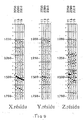
- la figure 7 est une représentation schématique des collections de traces suivant les axes R, N, T,
- la figure 8 est une représentation schématique des collections de traces R, R signal et R résiduelles,
- la figure 9 est une représentation schématique des projections des collections de traces R résiduelles, N et T sur les axes fixes géographiquement X, Y, Z,
- la figure 10 est une représentation schématique de la décomposition d'une collection de traces (z, t) à émetteur commun dans un domaine (τ, p),
- la figure 11 est une représentation schématique de la décomposition dans le domaine (τ, p) des collections de traces X, Y, Z de la figure 9,
- la figure 12 représente schématiquement, dans le système d'axes X, Y, Z, la synthèse de la trace pivot de la figure 10, représentative de l'estimation du champ d'onde P montante.


Claims (12)
- Méthode pour la séparation des ondes se propageant dans un milieu, du type consistant à :caractérisée en ce qu'elle consiste, en outre, àgénérer des ondes dans le milieu successivement à partir de plusieurs positions d'au moins un émetteur et situées à la surface dudit milieu,recevoir lesdites ondes sur au moins un récepteur susceptible d'occuper successivement au moins deux positions dans un puits foré dans le milieu, chaque récepteur comprenant trois capteurs orientés dans un premier système d'axes (V, H1, H2), un desdits axes (V) étant orienté suivant une direction déterminée, chaque capteur délivrant un signal qui est enregistré en fonction du temps sous forme d'une trace qui est repérée par les positions du couple émetteur-récepteur ayant produit ladite trace,constituer des collections de traces C à émetteur commun (z, t) à partir d'au moins un ensemble de traces V, H1, H2,a) extraire les premières arrivées C signal d'au moins une des collections de traces C,b) réaliser à partir de ladite collection de traces C une collection de traces C résiduelles dans laquelle chaque trace résiduelle est la différence entre la trace C et une estimation C signal,c) sélectionner dans la collection de traces C résiduelles une trace pivot située à une profondeur z,d) faire passer une droite de pente p variable en chaque point échantillonné de la trace pivot,e) sommer le long de ladite droite, pour chaque valeur de p, les amplitudes d'événements sismiques situés aux intersections des traces avec ladite droite,f) reporter les sommes amplitude pour les temps et pente correspondants dans un domaine (τ, p) dans lequel p représente les valeurs de ladite pente variant entre deux limites extrêmes et τ le temps,g) réaliser un sismogramme synthétique à partir des données du domaine (τ, p),h) comparer le sismogramme synthétique à la collection émetteur commun de traces C résiduelles,i) procéder à des itérations jusqu'à ce que le sismogramme synthétique soit acceptable par rapport aux données initiales de ladite collection émetteur commun des traces C résiduelles.
- Méthode selon la revendication 1, caractérisée en ce qu'elle consiste en outre àdéfinir pour chaque couple de positions émetteur-récepteur un deuxième système d'axes (R, N, T) qui est calculé, par des moyens connus, à partir des composantes suivant les trois axes V, H1, H2, du vecteur déplacement correspondant à la première arrivée de l'onde d'intérêt et de la projection Hmax dudit vecteur déplacement dans le plan H1, H2, l'axe R étant situé dans le plan V, Hmax, l'axe N étant perpendiculaire à l'axe R et situé dans le plan V, Hmax et l'axe T étant perpendiculaire au plan R, N,produire des traces dans le système d'axes R, N, T en projetant les composantes des traces repérées suivant les axes V, H1, H2,constituer les collections de traces (C) à émetteur commun (z, t) à partir d'au moins les traces R,extraire les premières arrivées R signal de la collection de traces R,réaliser à partir de la collection de traces R une collection de traces R résiduelles dans laquelle chaque trace résiduelle est la différence entre la trace R et l'estimation R signal,sélectionner dans la collection de traces R résiduelles une trace pivot située à une profondeur z,effectuer les étapes d) à i) sur les traces R résiduelles.
- Méthode selon la revendication 1 ou 2, caractérisée en ce qu'elle consiste en outre à :définir un troisième système d'axes (X, Y, Z), fixe géographiquement,déterminer dans le système d'axes (X, Y, Z) la déviation Ψ et l'azimut du puits,aligner l'axe V du premier système d'axes (V, H1, H2) avec la direction du puits,définir un vecteur h1 perpendiculaire aux axes V et Z et contenu dans le plan H1, H2,déterminer l'angle δ entre le vecteur h1 et l'axe H1.
- Méthode selon la revendication 3, caractérisée en ce qu'elle consiste en outre à projeter dans le système fixe (X, Y, Z) la composante résiduelle (C ou R) et les composantes associées H1 et H2 ou N et T pour constituer des composantes résiduelles Xr et Yr, Zr, sur les axes X, Y, Z la décomposition dans le domaine (τ, p) étant réalisée à partir des composantes de traces Xr et Yr, Zr.
- Méthode selon l'une des revendications 1 à 4, caractérisée en ce qu'elle consiste à calculer, par des moyens connus, pour chaque couple émetteur-récepteur, et dans le domaine (τ,p), un attribut angulaire polarisation ζ et un attribut angulaire azimut γ.
- Méthode selon la revendication 5, caractérisée en ce que l'onde d'intérêt est l'onde P et en ce qu'on utilise les attributs polarisation ζ, azimut γ, angle de déviation ψ et azimut du puits ainsi que la pente p pour calculer l'attribut (VP) de la vitesse des ondes P dans le milieu.
- Méthode selon la revendication 6, caractérisée en ce que l'attribut lenteur apparente pz par rapport à l'axe Z d'un événement sismique correspondant à des valeurs τ et p est calculé dans le domaine (τ, p) à partir des attributs polarisation ζ et VP.
- Méthode selon la revendication 7, caractérisée en ce que les attributs pz et VP sont utilisés pour opérer une sélection des événements à conserver dans le domaine (τ, p).
- Méthode selon la revendication 8, caractérisée en ce que les événements conservés sont ceux liés aux ondes P montantes.
- Méthode selon la revendication 1, caractérisée en ce qu'on construit une section synthétique, à partir des évènements conservés, représentative du champ d'onde P montant.
- Méthode selon les revendications 1 à 5, caractérisée en ce que l'onde d'intérêt est l'onde S
- Méthode selon la revendication 3, caractérisée en ce que lorsque l'axe du puits est vertical on fixe l'azimut dudit puits à une valeur nulle.
Applications Claiming Priority (2)
| Application Number | Priority Date | Filing Date | Title |
|---|---|---|---|
| FR9712622 | 1997-10-09 | ||
| FR9712622A FR2769718B1 (fr) | 1997-10-09 | 1997-10-09 | Procede de separation d'ondes en sismique de puits pour des acquisitions de type a deport croissant |
Publications (3)
| Publication Number | Publication Date |
|---|---|
| EP0909961A2 EP0909961A2 (fr) | 1999-04-21 |
| EP0909961A3 EP0909961A3 (fr) | 1999-05-06 |
| EP0909961B1 true EP0909961B1 (fr) | 2003-06-25 |
Family
ID=9512033
Family Applications (1)
| Application Number | Title | Priority Date | Filing Date |
|---|---|---|---|
| EP98402364A Expired - Lifetime EP0909961B1 (fr) | 1997-10-09 | 1998-09-25 | Procédé de séparation d'ondes en sismique de puits pour des acquisitions de type à déport croissant |
Country Status (6)
| Country | Link |
|---|---|
| US (1) | US6028821A (fr) |
| EP (1) | EP0909961B1 (fr) |
| CA (1) | CA2249969C (fr) |
| DE (1) | DE69815785T2 (fr) |
| FR (1) | FR2769718B1 (fr) |
| NO (1) | NO319315B1 (fr) |
Families Citing this family (5)
| Publication number | Priority date | Publication date | Assignee | Title |
|---|---|---|---|---|
| GB2362467B (en) | 2000-05-18 | 2004-03-31 | Schlumberger Ltd | A method of processing seismic data |
| FR2942045B1 (fr) * | 2009-02-12 | 2011-12-16 | Inst Francais Du Petrole | Methode de pointe-temps et d'orientation de signaux sismiques de puits a trois composantes |
| FR2945869B1 (fr) * | 2009-05-20 | 2011-05-20 | Inst Francais Du Petrole | Methode pour imager une zone cible du sous-sol a partir de donnees de type walkaway |
| US9291733B2 (en) * | 2011-01-31 | 2016-03-22 | Cggveritas Services Sa | Device and method for determining S-wave attenuation in near-surface condition |
| US20130242693A1 (en) * | 2012-03-13 | 2013-09-19 | Seoul National University R&Db Foundation | Seismic imaging system using a reverse time migration algorithm |
Family Cites Families (5)
| Publication number | Priority date | Publication date | Assignee | Title |
|---|---|---|---|---|
| FR2494450A1 (fr) * | 1980-11-14 | 1982-05-21 | Schlumberger Prospection | Procede d'exploration sismique par la technique du profil sismique vertical et installation pour sa mise en oeuvre |
| US4604734A (en) * | 1980-12-29 | 1986-08-05 | Mobil Oil Corporation | Seismic exploration in areas where p waves are converted to s waves |
| US4635238A (en) * | 1984-09-12 | 1987-01-06 | Phillips Petroleum Company | Data processing method for correcting P and S wave seismic traces |
| US4779238A (en) * | 1987-04-13 | 1988-10-18 | Conoco Inc. | Method for fast slant stack of seismic data |
| US5142501A (en) * | 1991-06-13 | 1992-08-25 | Chevron Research And Technology Company | Method of geophysical exploration by analyzing shear-wave polarization directions |
-
1997
- 1997-10-09 FR FR9712622A patent/FR2769718B1/fr not_active Expired - Fee Related
-
1998
- 1998-09-25 DE DE69815785T patent/DE69815785T2/de not_active Expired - Lifetime
- 1998-09-25 EP EP98402364A patent/EP0909961B1/fr not_active Expired - Lifetime
- 1998-09-30 NO NO19984558A patent/NO319315B1/no not_active IP Right Cessation
- 1998-10-05 CA CA002249969A patent/CA2249969C/fr not_active Expired - Fee Related
- 1998-10-07 US US09/168,228 patent/US6028821A/en not_active Expired - Fee Related
Also Published As
| Publication number | Publication date |
|---|---|
| US6028821A (en) | 2000-02-22 |
| CA2249969C (fr) | 2006-10-03 |
| DE69815785T2 (de) | 2004-06-17 |
| NO984558L (no) | 1999-04-12 |
| DE69815785D1 (de) | 2003-07-31 |
| FR2769718B1 (fr) | 1999-12-03 |
| EP0909961A2 (fr) | 1999-04-21 |
| NO984558D0 (no) | 1998-09-30 |
| CA2249969A1 (fr) | 1999-04-09 |
| EP0909961A3 (fr) | 1999-05-06 |
| FR2769718A1 (fr) | 1999-04-16 |
| NO319315B1 (no) | 2005-07-11 |
Similar Documents
| Publication | Publication Date | Title |
|---|---|---|
| EP0789849B1 (fr) | Methode pour representer dans un domaine spatio-temporel la trajectoire d'au moins un puits de forage | |
| EP1096270B1 (fr) | Méthode pour modeliser en 2d ou 3d un milieu hétérogène tel que le sous-sol décrit par un ou plusieurs paramètres physiques | |
| EP1624321B1 (fr) | Méthode pour construire un modèle d'un milieu hétérogène décrit par plusieurs paramètres à partir de données exprimées dans des échelles de temps différentes | |
| EP1669778B1 (fr) | Méthode pour déterminer de l'information spéculaire dans l'imagerie sismique avant sommation | |
| EP0249527B1 (fr) | Procédé et dispositif de traitement de données sismographique par corrélation | |
| CA2786411A1 (fr) | Procede et dispositif d'acquisition de donnees sismiques marines | |
| CA2670384A1 (fr) | Methode d'inversion conjointe de donnees sismiques representees sur des echelles de temps differentes | |
| CA2226389C (fr) | Methode de traitement de donnees sismiques de puits multi-composantes orientees | |
| FR2747477A1 (fr) | Methode d'inversion pour donnees sismiques | |
| US7474996B2 (en) | Method of processing geophysical data | |
| EP0909961B1 (fr) | Procédé de séparation d'ondes en sismique de puits pour des acquisitions de type à déport croissant | |
| EP0698220B1 (fr) | Procede de modelisation de donnees sismiques cinematiques ayant subi un traitement par au moins un operateur de deplacement | |
| AU2002317974A1 (en) | A method of processing geophysical data | |
| EP0944847B1 (fr) | Procede de traitement sismique et notamment procede de prospection sismique 3d mettant en oeuvre une migration des donnees sismiques | |
| US7889597B2 (en) | Method of processing seismic data acquired by means of multi-component sensors | |
| WO1998019180A1 (fr) | Methode perfectionnee de migration avant somme | |
| FR2751757A1 (fr) | Methode d'acquisition et de traitement de donnees sismiques reflexion pour l'exploration d'un milieu a tectonique complexe | |
| Lynn et al. | Efficient migration through complex water-bottom topography | |
| CA2085617A1 (fr) | Procede de traitement pour l'obtention d'une section somme a offsets nuls | |
| FR2650676A1 (fr) | Procede de traitement de donnees de sismique reflexion pour l'obtention de coupes sismiques ameliorees | |
| EP0888562A1 (fr) | Methode de migration des attributs geophysiques d'un milieu | |
| FR2703469A1 (fr) | Procédé de détection de l'existence d'une anisotropie azimutale dans une couche d'un sous-sol et de détermination de sa direction . | |
| WO1994010584A1 (fr) | Procede d'estimation de la position de reflecteurs acoustiques presents dans un milieu | |
| Audebert et al. | Improvement of Kirchhoff Migrated Images by Dip Selection and Steered Stacking on Multi-Angle Gathers |
Legal Events
| Date | Code | Title | Description |
|---|---|---|---|
| PUAI | Public reference made under article 153(3) epc to a published international application that has entered the european phase |
Free format text: ORIGINAL CODE: 0009012 |
|
| PUAL | Search report despatched |
Free format text: ORIGINAL CODE: 0009013 |
|
| AK | Designated contracting states |
Kind code of ref document: A2 Designated state(s): DE FR GB IT NL |
|
| AX | Request for extension of the european patent |
Free format text: AL;LT;LV;MK;RO;SI |
|
| AK | Designated contracting states |
Kind code of ref document: A3 Designated state(s): AT BE CH CY DE DK ES FI FR GB GR IE IT LI LU MC NL PT SE |
|
| AX | Request for extension of the european patent |
Free format text: AL;LT;LV;MK;RO;SI |
|
| 17P | Request for examination filed |
Effective date: 19990521 |
|
| AKX | Designation fees paid |
Free format text: DE FR GB IT NL |
|
| GRAH | Despatch of communication of intention to grant a patent |
Free format text: ORIGINAL CODE: EPIDOS IGRA |
|
| GRAH | Despatch of communication of intention to grant a patent |
Free format text: ORIGINAL CODE: EPIDOS IGRA |
|
| GRAA | (expected) grant |
Free format text: ORIGINAL CODE: 0009210 |
|
| AK | Designated contracting states |
Designated state(s): DE FR GB IT NL |
|
| REG | Reference to a national code |
Ref country code: GB Ref legal event code: FG4D Free format text: NOT ENGLISH |
|
| GBT | Gb: translation of ep patent filed (gb section 77(6)(a)/1977) | ||
| REF | Corresponds to: |
Ref document number: 69815785 Country of ref document: DE Date of ref document: 20030731 Kind code of ref document: P |
|
| PLBE | No opposition filed within time limit |
Free format text: ORIGINAL CODE: 0009261 |
|
| STAA | Information on the status of an ep patent application or granted ep patent |
Free format text: STATUS: NO OPPOSITION FILED WITHIN TIME LIMIT |
|
| 26N | No opposition filed |
Effective date: 20040326 |
|
| PGFP | Annual fee paid to national office [announced via postgrant information from national office to epo] |
Ref country code: NL Payment date: 20100824 Year of fee payment: 13 |
|
| PGFP | Annual fee paid to national office [announced via postgrant information from national office to epo] |
Ref country code: IT Payment date: 20100904 Year of fee payment: 13 |
|
| PGFP | Annual fee paid to national office [announced via postgrant information from national office to epo] |
Ref country code: GB Payment date: 20100826 Year of fee payment: 13 |
|
| PGFP | Annual fee paid to national office [announced via postgrant information from national office to epo] |
Ref country code: FR Payment date: 20101018 Year of fee payment: 13 |
|
| PGFP | Annual fee paid to national office [announced via postgrant information from national office to epo] |
Ref country code: DE Payment date: 20100909 Year of fee payment: 13 |
|
| REG | Reference to a national code |
Ref country code: NL Ref legal event code: V1 Effective date: 20120401 |
|
| GBPC | Gb: european patent ceased through non-payment of renewal fee |
Effective date: 20110925 |
|
| PG25 | Lapsed in a contracting state [announced via postgrant information from national office to epo] |
Ref country code: IT Free format text: LAPSE BECAUSE OF NON-PAYMENT OF DUE FEES Effective date: 20110925 |
|
| REG | Reference to a national code |
Ref country code: FR Ref legal event code: ST Effective date: 20120531 |
|
| REG | Reference to a national code |
Ref country code: DE Ref legal event code: R119 Ref document number: 69815785 Country of ref document: DE Effective date: 20120403 |
|
| PG25 | Lapsed in a contracting state [announced via postgrant information from national office to epo] |
Ref country code: DE Free format text: LAPSE BECAUSE OF FAILURE TO SUBMIT A TRANSLATION OF THE DESCRIPTION OR TO PAY THE FEE WITHIN THE PRESCRIBED TIME-LIMIT Effective date: 20120403 Ref country code: NL Free format text: LAPSE BECAUSE OF NON-PAYMENT OF DUE FEES Effective date: 20120401 |
|
| PG25 | Lapsed in a contracting state [announced via postgrant information from national office to epo] |
Ref country code: FR Free format text: LAPSE BECAUSE OF NON-PAYMENT OF DUE FEES Effective date: 20110930 Ref country code: GB Free format text: LAPSE BECAUSE OF NON-PAYMENT OF DUE FEES Effective date: 20110925 |