EP0909961A2 - Welletrennungverfahren für Borlochseismischen Wellen für Datenerfassung mit zunemenden Versatz - Google Patents
Welletrennungverfahren für Borlochseismischen Wellen für Datenerfassung mit zunemenden Versatz Download PDFInfo
- Publication number
- EP0909961A2 EP0909961A2 EP98402364A EP98402364A EP0909961A2 EP 0909961 A2 EP0909961 A2 EP 0909961A2 EP 98402364 A EP98402364 A EP 98402364A EP 98402364 A EP98402364 A EP 98402364A EP 0909961 A2 EP0909961 A2 EP 0909961A2
- Authority
- EP
- European Patent Office
- Prior art keywords
- traces
- axes
- trace
- collection
- residual
- Prior art date
- Legal status (The legal status is an assumption and is not a legal conclusion. Google has not performed a legal analysis and makes no representation as to the accuracy of the status listed.)
- Granted
Links
Images


Classifications
-
- G—PHYSICS
- G01—MEASURING; TESTING
- G01V—GEOPHYSICS; GRAVITATIONAL MEASUREMENTS; DETECTING MASSES OR OBJECTS; TAGS
- G01V1/00—Seismology; Seismic or acoustic prospecting or detecting
- G01V1/28—Processing seismic data, e.g. for interpretation or for event detection
- G01V1/282—Application of seismic models, synthetic seismograms
-
- G—PHYSICS
- G01—MEASURING; TESTING
- G01V—GEOPHYSICS; GRAVITATIONAL MEASUREMENTS; DETECTING MASSES OR OBJECTS; TAGS
- G01V1/00—Seismology; Seismic or acoustic prospecting or detecting
- G01V1/28—Processing seismic data, e.g. for interpretation or for event detection
- G01V1/36—Effecting static or dynamic corrections on records, e.g. correcting spread; Correlating seismic signals; Eliminating effects of unwanted energy
- G01V1/364—Seismic filtering
-
- G—PHYSICS
- G01—MEASURING; TESTING
- G01V—GEOPHYSICS; GRAVITATIONAL MEASUREMENTS; DETECTING MASSES OR OBJECTS; TAGS
- G01V2210/00—Details of seismic processing or analysis
- G01V2210/20—Trace signal pre-filtering to select, remove or transform specific events or signal components, i.e. trace-in/trace-out
-
- G—PHYSICS
- G01—MEASURING; TESTING
- G01V—GEOPHYSICS; GRAVITATIONAL MEASUREMENTS; DETECTING MASSES OR OBJECTS; TAGS
- G01V2210/00—Details of seismic processing or analysis
- G01V2210/60—Analysis
- G01V2210/61—Analysis by combining or comparing a seismic data set with other data
- G01V2210/614—Synthetically generated data
Definitions
- the present invention relates to a method for separation elastic waves received and recorded after propagation in a medium and, more particularly, the processing of the signals recorded during a acquisition by emission of elastic waves in several positions one or more transmitters arranged on the surface of the medium, the receptors being fixed in a well drilled in said medium during the entire transmission series, the receiver (s) then being moved to another position in the well for another series of emissions.
- Such an acquisition is usually designated by the English term "walkaway", that is to say that the transmission is carried out with increasing offset from one transmission to the next.
- a receiving tool is lowered into the well, the direction of which can be vertical or deviated.
- the tool generally comprises several receivers separated by a constant distance or not which is generally different from the constant distance or not separating two consecutive transmitters or sources.
- Each receiver comprises three sensors or geophones which are oriented in three different generally orthogonal directions, one of the directions being determined to have a reference axis.
- the reference axis can be non-vertical or vertical if these sensors are mounted on a universal joint system. In both cases, the reference axis V of the sensors is perpendicular to the plane defined by the two other directions H 1 and H 2 whose positions are not generally known.
- the axes V, H 1 , H 2 constitute a first system of axes.
- Signals representative of waves propagating in the environment are recorded as a function of time in the form of traces.
- the waves that propagate in the medium are mainly the rising P waves or descending (direct waves) and S waves
- the traces recorded along the axes V, H 1 ′, H 2 can be grouped into collections of traces with a common emitter for example.
- a current treatment of the traces consists in defining a second system of axes R, N, T, in which the axis R is located in the plane of maximum energy.
- Such a transformation is carried out using what is usually called a double rotation, a rotation of angle ⁇ H being carried out around the axis V and the second rotation of angle ⁇ V being carried out around a direction called H min which is perpendicular to a vector H max , which is the projection of the direct downward wave in the plane defined by H 1 and H 2 , the angle ⁇ H being the angle which H 1 and H max .
- the angle ⁇ V is the angle formed by the axes V and R.
- This transformation of the first system of axes V, H 1 , H 2 into a second system of axes R, N, T is carried out in particular at using software well known to specialists and called SEISLINK, marketed by the company WESTERN.
- Traces can be produced in the system of axes R, N, T by projecting the components of the traces identified along the axes V, H 1 , H 2 and constituting collections of traces with common emitter identified as a function of the depth z and of time t, from at least the traces along the R axis (or R traces).
- Trace collections for example collections V, R or N, are then processed to separate the different types of waves, especially the falling and rising P waves and the rising S waves and descending.
- a technique for separating said waves can be implemented. works using the SEPAR software from Compagnie i de Geophysics (CGG). However, this requires knowing the speeds apparent from the types of waves sought. Generally, these speeds apparent are determined using a manual pointing on the traces saved. The disadvantages of this technique lie in the imprecision inherent in manual pointing and sometimes the impossibility of discern the types of waves directly on the recorded traces. Moreover, the cost of treatment is high for imprecise results.
- Another technique recommended by the company SCHLUMBERGER is to use software that is capable of analyzing collections of traces with a common emitter and deduce the speeds apparent waves to be separated when they exist.
- a disadvantage of this technique resides in its instability and especially in the fact that the wave separation is ineffective due to the low number of sensors used.
- the present invention relates to a new method of separation of elastic waves, in which a special treatment of trace collections which makes it possible to remedy the disadvantages of previous methods as briefly described above.
- the residual components C or R, as well as the components H 1 and H 2 or N and T are projected into the fixed system (X, Y, Z) to constitute residual components X r and Y r , Z r , on the axes X, Y, Z, the decomposition ( ⁇ , p) being carried out from the components of the traces X r and Y r , Z r .
- one calculates, by means known, for each transmitter-receiver pair and in the fields ( ⁇ , p), an angular attribute polarization ⁇ and an angular attribute azimuth ⁇ .
- the wave of interest is the P wave
- the attributes p z and Vp can be used to make a selection (mute) of the events to be kept in the domain ( ⁇ , p), said events being in particular those linked to the rising P waves.
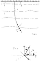
- one or more seismic sources or emitters 1 are used (FIG. 1) which are arranged on the surface 2 of a medium 3 in which a well 4 has been drilled.
- the well 4 can be vertical or deviated as in Figure 1.
- a receiving device 5 which can occupy at least two positions in the well.
- the reception device can comprise one or more receivers, for example four receivers 6 each consisting of three sensors whose directions are along a right-angled trihedron formed by three axes, V, H 1 , H 2 , the V axis being directed along the axis 7 of the well 4, the other axes H 1 and H 2 being located in a plane perpendicular to the axis V ( Figure 2).
- the distance between two consecutive positions of the transmitter 1 is generally constant and for example equal to 25 m, while the distance between two consecutive receivers 6 is generally constant and for example equal to 10 m.
- the deviation ⁇ and the azimuth ⁇ of the axis 7 of the well 4 are determined in a system of orthogonal axes X, Y, Z, fixed geographically, the axis Z being vertical (FIG. 3).
- the coordinates of the vector V are given as a function of ⁇ and ⁇ by the following formulas, in the system of axes X, Y, Z: the angles ⁇ and ⁇ being respectively included in the intervals [0, ⁇ / 2] and [0, 2 ⁇ ].
- a new vector h 1 is defined to be perpendicular both to the vector V and to the axis Z, and whose coordinates are given by the following formulas, in the system of axes X, Y, Z:
- the vector h 1 is then contained in the plane H 1 , H 2 .
- ⁇ represents the angle formed by the axis H 1 and the vector h 1 ( Figure 4).
- the transmitter 1 successively occupies several positions on the surface 2, said positions of the transmitter 1 being located along given geometric configurations, rectangular or circular concentric around the drilled well 4.
- the offset between the transmitter 1 and the receiving device 5 increases from one transmission to another, so as to carry out an acquisition of the walkaway type.
- the transmitter 1 generates elastic waves which propagate in the medium 3 and which are received and recorded on each of the sensors of each receiver 6 of the reception device 5, the waves being recorded as a function of time t in the form of traces in directions V, H 1 and H 2 .
- a set of traces is obtained which are identified by the depth z of the receiver 6 and the position of the transmitter 1.
- another transmission is carried out for a another position of the transmitter and so on for all the predetermined positions of the emission points.
- the receiving device 5 is moved to another depth in the well 4, as shown in FIG. 1 in which the lower receiver 6 comes to occupy the position 6 ′.
- Each trace recorded on each sensor that is to say in the directions V, H 1 , H 2 , is identified by the positions of the transmitter 1-receiver 6 pair having produced said trace.
- the processing consists first of all in extracting the first arrivals C signal from at least one of the collections of traces C and in producing a collection of residual traces C from said collection of traces C, each residual trace being the difference between the trace C and the C signal estimate.
- a pivot trace, located at a depth z is selected from the collection of residual traces C, then a line of slope p is passed which is variable at each sampled point of the pivot trace. For each value of p, a summation is made of the amplitudes of the seismic events which are located at the intersections of the traces with said straight line.
- ⁇ , p The amplitude sums for the corresponding times and slope are reported in a domain ( ⁇ , p) in which ⁇ is the time and p represents the values of said slope varying between two extreme limits. From the data in the domain ( ⁇ , p), a synthetic seismogram is produced. The synthetic seismogram is then compared to the collection with a common emitter of residual C traces. Finally, iterations are carried out until the synthetic seismogram is acceptable with respect to the initial data of the common emitter collection of the residual traces C.
- the processing consists in defining, for each pair of transmitter-receiver positions, a second system of orthogonal axes R, N, T which is calculated from the components along the three axes V, H 1 , H 2 of the displacement vector corresponding to the first arrival of the wave of interest, for example the P wave, and of the projection H max of the displacement vector in the plane H 1 , H 2 .
- Most of the energy associated with the wave of interest P or direct wave is located on this axis R which corresponds to said displacement vector.
- the N axis is perpendicular to the R axis and it is located in the V, H max plane and the T axis is perpendicular to the R, N plane ( Figure 5).
- the transition from the system of axes V, H 1 , H 2 to the system of axes R, N, T is effected by a rotation of angle ⁇ H around the axis V and another rotation of angle ⁇ V around of a vector H min which is perpendicular to the vector H max .
- the angles ⁇ H and ⁇ V are calculated from the three components V, H 1 , H 2 present in a time window located around the direct arrival.
- the angles ⁇ H and ⁇ V can be calculated using for example the SEISLINK software (version 1996) sold by the company WESTERN.
- the angle ⁇ is calculated for each reception position, using an inversion process which uses the angles ⁇ H , the relative positions of the transmitter relative to the receiver, the deviation ⁇ and the azimuth ⁇ of Wells.
- the value of the angle ⁇ is calculated by minimizing the following function: in which ⁇ represents the angle formed by the plane containing the transmitter-receiver pair and the X axis.
- CEPHAG-IFP filtering technique matrix
- this invention For each initial R collection, this invention consists in providing, at output, a common transmitter collection called R signal. These signals constituting the estimation of the P field descending for the source position considered.
- R signal a common transmitter collection
- a sender collection common R residual or R residual is obtained by difference between the initial collection R and estimate R signal ( Figure 8).
- the R signal collections thus estimated can be used later for the calculation of the anti-multiple operators.
- the residual components R, N and T are projected into the fixed coordinate system X, Y, Z, using the angles ⁇ H , ⁇ V and ⁇ as well as the deviation ⁇ and the azimuth ⁇ of the well.
- the components thus obtained are called X residue, Y residue and Z residue ( Figure 9).
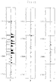
- Figure 10 schematically represents a collection of residual traces common transmitter.
- a pivot trace 10 located at a depth z.
- FIG. 11 represents the decomposition in the domain ( ⁇ , p) of the collections of traces X residue, Y residue and Z residue, of FIG. 9. From the decomposition in the domain ( ⁇ , p) of the components X residue, Y residue and Z residue, we calculate the polarization attribute ⁇ and the azimuth attribute ⁇ for each value of p and ⁇ and this, on a sliding window, using the eigen elements of the variance and covariance matrix included in the aforementioned software SEISLINK.
- V P ( ⁇ , p) (cos [polar ( ⁇ , p)] cos ⁇ + sin [polar ( ⁇ , p)] sin ⁇ cos [azi ( ⁇ , p) - ⁇ ]) p
- the axis Z being vertical, the slowness p z ( ⁇ , p) is used to discriminate the rising events from the falling events.
- Identical processing can be performed to extract the falling and rising S wave fields.
- the method according to the invention is more flexible than the methods optimal filtering or parametric inversion. It does not require no pointing apart from that of the first arrival and it is not necessary to define the number of waves to extract; moreover, it is not necessary to determine the apparent speeds.
- the method according to the invention is therefore very simple of use and it can be used as is for 3D acquisitions. In addition, it provides an opportunity to analyze data and control the result of separation.
- the collections of traces R, N, T can be replaced by the collections C obtained from the components V, H 1 , H 2 , the other steps of the method according to the invention being carried out on said collections C so as to obtain the collections of residual traces C necessary for decomposition in the domain ( ⁇ , p).
- the present invention can be applied for fine imaging of tanks as well as for the calibration of AVO measurements (measurement of reflection coefficient versus angle of incidence). Indeed, from walkaway data, it is possible to measure incident fields and reflected and by deconvolution, to make a possible estimate of the coefficient of reflection, this measurement being all the more exact as the sensor is located near the objective studied. Furthermore, polarization analyzes lead knowledge of the angles of incidence. We therefore have all the elements to assess without bias the behavior of the reflection coefficient vis-à-vis of the angle of incidence.
- the present invention can be used for the measurement of anisotropy at the line of the receiving device, said anisotropy obtainable by a joint speed analysis apparent and the polarization of the direct arrival.
Landscapes
- Engineering & Computer Science (AREA)
- Remote Sensing (AREA)
- Physics & Mathematics (AREA)
- Life Sciences & Earth Sciences (AREA)
- Acoustics & Sound (AREA)
- Environmental & Geological Engineering (AREA)
- Geology (AREA)
- General Life Sciences & Earth Sciences (AREA)
- General Physics & Mathematics (AREA)
- Geophysics (AREA)
- Geophysics And Detection Of Objects (AREA)
- Vibration Prevention Devices (AREA)
Applications Claiming Priority (2)
| Application Number | Priority Date | Filing Date | Title |
|---|---|---|---|
| FR9712622 | 1997-10-09 | ||
| FR9712622A FR2769718B1 (fr) | 1997-10-09 | 1997-10-09 | Procede de separation d'ondes en sismique de puits pour des acquisitions de type a deport croissant |
Publications (3)
| Publication Number | Publication Date |
|---|---|
| EP0909961A2 true EP0909961A2 (de) | 1999-04-21 |
| EP0909961A3 EP0909961A3 (de) | 1999-05-06 |
| EP0909961B1 EP0909961B1 (de) | 2003-06-25 |
Family
ID=9512033
Family Applications (1)
| Application Number | Title | Priority Date | Filing Date |
|---|---|---|---|
| EP98402364A Expired - Lifetime EP0909961B1 (de) | 1997-10-09 | 1998-09-25 | Welletrennungverfahren für Borlochseismischen Wellen für Datenerfassung mit zunemenden Versatz |
Country Status (6)
| Country | Link |
|---|---|
| US (1) | US6028821A (de) |
| EP (1) | EP0909961B1 (de) |
| CA (1) | CA2249969C (de) |
| DE (1) | DE69815785T2 (de) |
| FR (1) | FR2769718B1 (de) |
| NO (1) | NO319315B1 (de) |
Cited By (2)
| Publication number | Priority date | Publication date | Assignee | Title |
|---|---|---|---|---|
| WO2001088570A1 (en) * | 2000-05-18 | 2001-11-22 | Schlumberger Limited | Seismic method of performing the time picking step |
| EP2253970A1 (de) * | 2009-05-20 | 2010-11-24 | IFP Energies nouvelles | Methode zur Bilderzeugung einer Zielzone im Untergrund auf der Grundlage von Daten vom Typ Walkaway |
Families Citing this family (3)
| Publication number | Priority date | Publication date | Assignee | Title |
|---|---|---|---|---|
| FR2942045B1 (fr) * | 2009-02-12 | 2011-12-16 | Inst Francais Du Petrole | Methode de pointe-temps et d'orientation de signaux sismiques de puits a trois composantes |
| US9291733B2 (en) * | 2011-01-31 | 2016-03-22 | Cggveritas Services Sa | Device and method for determining S-wave attenuation in near-surface condition |
| KR101413751B1 (ko) * | 2012-03-13 | 2014-07-01 | 서울대학교산학협력단 | 역시간 구조보정 알고리즘을 사용한 탄성파 영상화 시스템 |
Family Cites Families (5)
| Publication number | Priority date | Publication date | Assignee | Title |
|---|---|---|---|---|
| FR2494450A1 (fr) * | 1980-11-14 | 1982-05-21 | Schlumberger Prospection | Procede d'exploration sismique par la technique du profil sismique vertical et installation pour sa mise en oeuvre |
| US4604734A (en) * | 1980-12-29 | 1986-08-05 | Mobil Oil Corporation | Seismic exploration in areas where p waves are converted to s waves |
| US4635238A (en) * | 1984-09-12 | 1987-01-06 | Phillips Petroleum Company | Data processing method for correcting P and S wave seismic traces |
| US4779238A (en) * | 1987-04-13 | 1988-10-18 | Conoco Inc. | Method for fast slant stack of seismic data |
| US5142501A (en) * | 1991-06-13 | 1992-08-25 | Chevron Research And Technology Company | Method of geophysical exploration by analyzing shear-wave polarization directions |
-
1997
- 1997-10-09 FR FR9712622A patent/FR2769718B1/fr not_active Expired - Fee Related
-
1998
- 1998-09-25 EP EP98402364A patent/EP0909961B1/de not_active Expired - Lifetime
- 1998-09-25 DE DE69815785T patent/DE69815785T2/de not_active Expired - Lifetime
- 1998-09-30 NO NO19984558A patent/NO319315B1/no not_active IP Right Cessation
- 1998-10-05 CA CA002249969A patent/CA2249969C/fr not_active Expired - Fee Related
- 1998-10-07 US US09/168,228 patent/US6028821A/en not_active Expired - Fee Related
Cited By (5)
| Publication number | Priority date | Publication date | Assignee | Title |
|---|---|---|---|---|
| WO2001088570A1 (en) * | 2000-05-18 | 2001-11-22 | Schlumberger Limited | Seismic method of performing the time picking step |
| US6868038B2 (en) | 2000-05-18 | 2005-03-15 | Schlumberger Technology Corporation | Seismic method of performing the time picking step |
| EP2253970A1 (de) * | 2009-05-20 | 2010-11-24 | IFP Energies nouvelles | Methode zur Bilderzeugung einer Zielzone im Untergrund auf der Grundlage von Daten vom Typ Walkaway |
| FR2945869A1 (fr) * | 2009-05-20 | 2010-11-26 | Inst Francais Du Petrole | Methode pour imager une zone cible du sous-sol a partir de donnees de type walkaway |
| US8531914B2 (en) | 2009-05-20 | 2013-09-10 | Ifp | Method of imaging a target area of the subsoil from walkaway type data |
Also Published As
| Publication number | Publication date |
|---|---|
| DE69815785T2 (de) | 2004-06-17 |
| CA2249969C (fr) | 2006-10-03 |
| NO984558L (no) | 1999-04-12 |
| US6028821A (en) | 2000-02-22 |
| EP0909961B1 (de) | 2003-06-25 |
| NO984558D0 (no) | 1998-09-30 |
| NO319315B1 (no) | 2005-07-11 |
| FR2769718B1 (fr) | 1999-12-03 |
| EP0909961A3 (de) | 1999-05-06 |
| FR2769718A1 (fr) | 1999-04-16 |
| CA2249969A1 (fr) | 1999-04-09 |
| DE69815785D1 (de) | 2003-07-31 |
Similar Documents
| Publication | Publication Date | Title |
|---|---|---|
| EP0789849B1 (de) | Verfahren zur darstellung des verlaufs mindestens eines bohrlochs in einem raum-zeitlichen bereich | |
| EP1096270B1 (de) | Methode zur 2D oder 3D Modellerstellung einer heterogenen Umgebung, wie z.B. des Bodenuntergrundes, beschrieben durch einen oder mehrere physikalische Parameter | |
| EP1624321B1 (de) | Methode zur Erstellung eines heterogenen Untergrundmodells beschrieben durch mehrere Parameter welche Daten in unterschiedlichen Zeitskalen darstellen. | |
| EP0861450B1 (de) | Mehrfach vibrator einstufiger inversion trennungsverfahren | |
| EP0249527B1 (de) | Verfahren und Anordnung zur seismischen Datenverarbeitung durch Korrelation | |
| CA2786411A1 (fr) | Procede et dispositif d'acquisition de donnees sismiques marines | |
| WO2010092249A2 (fr) | Methode de pointe-temps et d'orientation de signaux sismiques de puits a trois composantes | |
| FR2782389A1 (fr) | Procede et dispositif pour corriger les effets des deplacements du navire dans les mesures de sismique maritime | |
| EP2253970A1 (de) | Methode zur Bilderzeugung einer Zielzone im Untergrund auf der Grundlage von Daten vom Typ Walkaway | |
| CA2226389C (fr) | Methode de traitement de donnees sismiques de puits multi-composantes orientees | |
| FR2747477A1 (fr) | Methode d'inversion pour donnees sismiques | |
| FR2858063A1 (fr) | Procede d'estimation du taux de couverture d'illumination dans le domaine migre | |
| EP1669778B1 (de) | Verfahren zur Bestimmung von Spiegelinformation bei der seismischen Bildbestimmung und vor Summation | |
| US7474996B2 (en) | Method of processing geophysical data | |
| EP0909961B1 (de) | Welletrennungverfahren für Borlochseismischen Wellen für Datenerfassung mit zunemenden Versatz | |
| AU2002317974A1 (en) | A method of processing geophysical data | |
| EP0698220B1 (de) | Verfahren zur modellisierung von kinematischen seismischen daten,die durch mindestens einen bewegungsoperator bearbeitet worden sind | |
| EP0944847B1 (de) | Verfahren zur seismischen verarbeitung und insbesondere seismisches prospektionsverfahren zur durchführung einer seismischen migration | |
| US7889597B2 (en) | Method of processing seismic data acquired by means of multi-component sensors | |
| EP0879428A1 (de) | Verbessertes verfahren für prestack migration | |
| FR2751757A1 (fr) | Methode d'acquisition et de traitement de donnees sismiques reflexion pour l'exploration d'un milieu a tectonique complexe | |
| Lynn et al. | Efficient migration through complex water-bottom tomography | |
| CA2085617A1 (fr) | Procede de traitement pour l'obtention d'une section somme a offsets nuls | |
| FR2703469A1 (fr) | Procédé de détection de l'existence d'une anisotropie azimutale dans une couche d'un sous-sol et de détermination de sa direction . | |
| EP0458947A1 (de) | Verfahren und vorrichtung zur datenerfassung von seismischen messwerten aus bohrlöchern in zwei entgegengesetzten richtungen. |
Legal Events
| Date | Code | Title | Description |
|---|---|---|---|
| PUAI | Public reference made under article 153(3) epc to a published international application that has entered the european phase |
Free format text: ORIGINAL CODE: 0009012 |
|
| PUAL | Search report despatched |
Free format text: ORIGINAL CODE: 0009013 |
|
| AK | Designated contracting states |
Kind code of ref document: A2 Designated state(s): DE FR GB IT NL |
|
| AX | Request for extension of the european patent |
Free format text: AL;LT;LV;MK;RO;SI |
|
| AK | Designated contracting states |
Kind code of ref document: A3 Designated state(s): AT BE CH CY DE DK ES FI FR GB GR IE IT LI LU MC NL PT SE |
|
| AX | Request for extension of the european patent |
Free format text: AL;LT;LV;MK;RO;SI |
|
| 17P | Request for examination filed |
Effective date: 19990521 |
|
| AKX | Designation fees paid |
Free format text: DE FR GB IT NL |
|
| GRAH | Despatch of communication of intention to grant a patent |
Free format text: ORIGINAL CODE: EPIDOS IGRA |
|
| GRAH | Despatch of communication of intention to grant a patent |
Free format text: ORIGINAL CODE: EPIDOS IGRA |
|
| GRAA | (expected) grant |
Free format text: ORIGINAL CODE: 0009210 |
|
| AK | Designated contracting states |
Designated state(s): DE FR GB IT NL |
|
| REG | Reference to a national code |
Ref country code: GB Ref legal event code: FG4D Free format text: NOT ENGLISH |
|
| GBT | Gb: translation of ep patent filed (gb section 77(6)(a)/1977) | ||
| REF | Corresponds to: |
Ref document number: 69815785 Country of ref document: DE Date of ref document: 20030731 Kind code of ref document: P |
|
| PLBE | No opposition filed within time limit |
Free format text: ORIGINAL CODE: 0009261 |
|
| STAA | Information on the status of an ep patent application or granted ep patent |
Free format text: STATUS: NO OPPOSITION FILED WITHIN TIME LIMIT |
|
| 26N | No opposition filed |
Effective date: 20040326 |
|
| PGFP | Annual fee paid to national office [announced via postgrant information from national office to epo] |
Ref country code: NL Payment date: 20100824 Year of fee payment: 13 |
|
| PGFP | Annual fee paid to national office [announced via postgrant information from national office to epo] |
Ref country code: IT Payment date: 20100904 Year of fee payment: 13 |
|
| PGFP | Annual fee paid to national office [announced via postgrant information from national office to epo] |
Ref country code: GB Payment date: 20100826 Year of fee payment: 13 |
|
| PGFP | Annual fee paid to national office [announced via postgrant information from national office to epo] |
Ref country code: FR Payment date: 20101018 Year of fee payment: 13 |
|
| PGFP | Annual fee paid to national office [announced via postgrant information from national office to epo] |
Ref country code: DE Payment date: 20100909 Year of fee payment: 13 |
|
| REG | Reference to a national code |
Ref country code: NL Ref legal event code: V1 Effective date: 20120401 |
|
| GBPC | Gb: european patent ceased through non-payment of renewal fee |
Effective date: 20110925 |
|
| PG25 | Lapsed in a contracting state [announced via postgrant information from national office to epo] |
Ref country code: IT Free format text: LAPSE BECAUSE OF NON-PAYMENT OF DUE FEES Effective date: 20110925 |
|
| REG | Reference to a national code |
Ref country code: FR Ref legal event code: ST Effective date: 20120531 |
|
| REG | Reference to a national code |
Ref country code: DE Ref legal event code: R119 Ref document number: 69815785 Country of ref document: DE Effective date: 20120403 |
|
| PG25 | Lapsed in a contracting state [announced via postgrant information from national office to epo] |
Ref country code: DE Free format text: LAPSE BECAUSE OF FAILURE TO SUBMIT A TRANSLATION OF THE DESCRIPTION OR TO PAY THE FEE WITHIN THE PRESCRIBED TIME-LIMIT Effective date: 20120403 Ref country code: NL Free format text: LAPSE BECAUSE OF NON-PAYMENT OF DUE FEES Effective date: 20120401 |
|
| PG25 | Lapsed in a contracting state [announced via postgrant information from national office to epo] |
Ref country code: FR Free format text: LAPSE BECAUSE OF NON-PAYMENT OF DUE FEES Effective date: 20110930 Ref country code: GB Free format text: LAPSE BECAUSE OF NON-PAYMENT OF DUE FEES Effective date: 20110925 |