EP0909948A2 - Method for testing presence of cracks in hardwood surfaces - Google Patents
Method for testing presence of cracks in hardwood surfaces Download PDFInfo
- Publication number
- EP0909948A2 EP0909948A2 EP98115953A EP98115953A EP0909948A2 EP 0909948 A2 EP0909948 A2 EP 0909948A2 EP 98115953 A EP98115953 A EP 98115953A EP 98115953 A EP98115953 A EP 98115953A EP 0909948 A2 EP0909948 A2 EP 0909948A2
- Authority
- EP
- European Patent Office
- Prior art keywords
- section
- cracks
- light
- conveyor belt
- sections
- Prior art date
- Legal status (The legal status is an assumption and is not a legal conclusion. Google has not performed a legal analysis and makes no representation as to the accuracy of the status listed.)
- Withdrawn
Links
- 238000000034 method Methods 0.000 title claims abstract description 23
- 239000011121 hardwood Substances 0.000 title claims abstract description 15
- 238000012360 testing method Methods 0.000 title claims abstract description 9
- 238000001514 detection method Methods 0.000 claims abstract description 4
- 239000002023 wood Substances 0.000 claims description 17
- 230000001066 destructive effect Effects 0.000 abstract description 2
- 230000023077 detection of light stimulus Effects 0.000 abstract description 2
- 230000007547 defect Effects 0.000 description 2
- 238000011161 development Methods 0.000 description 2
- 230000018109 developmental process Effects 0.000 description 2
- 238000004458 analytical method Methods 0.000 description 1
- 238000006073 displacement reaction Methods 0.000 description 1
- 230000037406 food intake Effects 0.000 description 1
- 238000003703 image analysis method Methods 0.000 description 1
- 239000007788 liquid Substances 0.000 description 1
- 238000004519 manufacturing process Methods 0.000 description 1
- 239000011159 matrix material Substances 0.000 description 1
- 238000009659 non-destructive testing Methods 0.000 description 1
- 230000000149 penetrating effect Effects 0.000 description 1
- 238000000275 quality assurance Methods 0.000 description 1
Images

Classifications
-
- G—PHYSICS
- G01—MEASURING; TESTING
- G01N—INVESTIGATING OR ANALYSING MATERIALS BY DETERMINING THEIR CHEMICAL OR PHYSICAL PROPERTIES
- G01N21/00—Investigating or analysing materials by the use of optical means, i.e. using sub-millimetre waves, infrared, visible or ultraviolet light
- G01N21/84—Systems specially adapted for particular applications
- G01N21/88—Investigating the presence of flaws or contamination
- G01N21/89—Investigating the presence of flaws or contamination in moving material, e.g. running paper or textiles
- G01N21/892—Investigating the presence of flaws or contamination in moving material, e.g. running paper or textiles characterised by the flaw, defect or object feature examined
- G01N21/8921—Streaks
Definitions
- the invention relates to a method for checking Hardwood surfaces on cracks, especially hairline cracks.
- the invention has for its object a method of type mentioned and a device for this specify that by non-destructive testing Cracks and hairline cracks in hardwoods are safe and unambiguous recognizes and thus a quality assuring sorting of Allows wood products.
- the task is in a procedure in the preamble of Claim 1 or a device in the preamble of Claim 9 each specified genus according to the invention by the features in the characterizing part of claim 1 or of claim 9 solved.
- the method according to the invention or the one according to the invention Device has the advantage that when the the cracks in the two sections over the wooden surface Area of the first section are illuminated. This in the light penetrating the crack is reflected here several times and thereby passes into the second, monitored for light Section into which the crack extends. So that will the crack in the second section was correctly recognized, and Faults caused by appearances that are visually a crack same, but are not a crack, are excluded; because these appearances remain dark in the second section, because they are unable to turn their way into the light forward the second section. With the invention Method and the device according to the invention so that even the smallest hairline cracks are still recognized a quality-reducing influence on the wood product e.g.
- parquet stick because they e.g. the parquet stick break under stress or by ingestion of Allow moisture and liquids to swell. So that is the wood product manufacturer a reliable process or given a reliable device, one quality-assuring sorting of its products specifically Carry out cracks automatically, not just one Sorting "cracks / no cracks" but also one Quality gradation according to the frequency of the cracks can be made per surface unit.
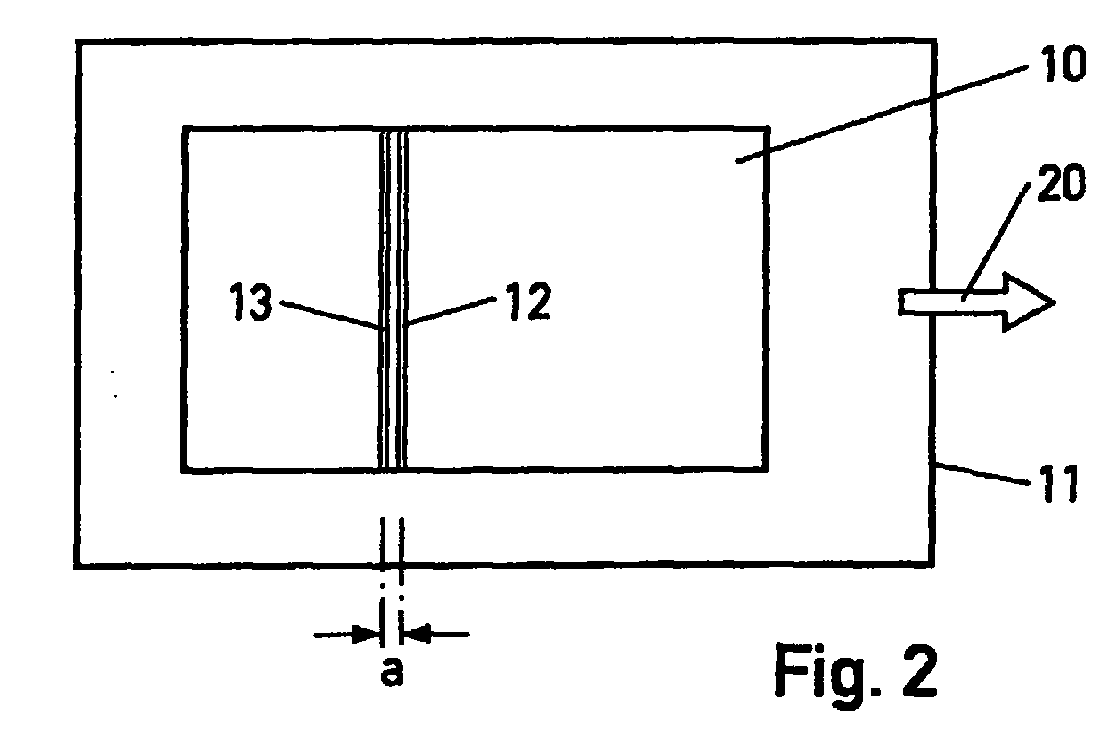
- a hardwood test piece 11 On the wooden surface 10 of a hardwood test piece 11, e.g. a parquet stick or a package of adjacent individual parquet strips, becomes an elongated, narrow, first section 12 illuminated and a parallel to it in short distance extending elongated, narrow, unilluminated second section 13 on light supervised.
- the two sections 12, 13 are so aligned that they are transverse to the main grain of the Extend wooden surface 10.
- the distance a between the two distances 12, 13 is minimized and set so that with an undisturbed wooden surface, i.e. with no cracks of the illuminated first section 12, no light in the unlit second section 13 falls.
- the distance a between the two sections 12, 13 typically about 1 mm.
- the two sections 12, 13 are in a spatially rigid assignment across from her Direction of extension over the wooden surface 10 led away and the detection of light in the second Section 13 assessed as the presence of cracks.
- To the Lead away the two sections 12, 13 on the Wood surface 10 is preferably the wood surface 10, So the hardwood test specimen 11, relative to the spatially fixed Arrangement of the two sections 12, 13 continuously postponed.
- the first section 12 is projected by a Light streak 14 generated on the wooden surface 10 while the second section of the reception field 15 one photosensitive line detector is formed. If you divide the reception field 15 into a plurality of adjacent reception cells that selectively Light can be monitored, so not only the presence of cracks, but also the number of each with the Light bar 14 illuminated cracks can be found.
- the schematically sketched in Fig.1 in side view Device for performing the above Process preferably has a continuous driven conveyor belt 16 to support the Hardwood test specimens 11, a laser light source 17, a Line camera 18 and an image processing unit 19.
- the laser light source 17 projects one across Transport direction 20 of the conveyor belt 16 itself extending laser line, which gives the light line 14, on the conveyor belt 16 and thus on the surface 10 of the hardwood test specimen 11, the laser light source 17 generates a bundled laser beam, which by means of a Cylinder lens or a collimator in the plane transverse to Transport direction 20 of the conveyor belt 16 expanded becomes.
- the high-resolution line camera 18 spans the Conveyor belt 16 on the receiving field 15 that the first Section 13 corresponds. There is still one on the conveyor belt 16 Position sensor 22 is provided, that of the image processing unit 19 for the displacement path of the conveyor belt 16 delivers characteristic output signals.
- the Output signals of the line camera 18 are also the Image processing unit 19 supplied.
- Hardwood test specimen 11 on the arrangement of laser light source 17 and line camera 18 preferably continuously is passed by, then migrate from the laser light source 17 projected laser light line 14 and that of the Line camera 18 spanned reception field 15 in the fixed Distance a to each other gradually over the entire Wood surface 10 away. Appears at least one crack the wooden surface 10 in the laser light line 14, so occurs in the receiving field 15 of the line camera 18 light on by the line camera 18 is recorded.
- the image signals of the Line camera 18 are composed with the Output signals of the encoder 22 a perfect image the crack distribution over the wooden surface 10.
- the Determination of the number and length of cracks in the of of the image processing unit 19 generated digital image is easily possible and is from the Image processing unit 19 automatically ejected and can be shown in a display 23.
- the image processing unit 19 can also produce a sorting signal generate, which is fed to a sorting device 24, the tested hardwood specimen 11 according to the Number of cracks found per unit area in one of predetermined quality levels.
Landscapes
- Analytical Chemistry (AREA)
- Immunology (AREA)
- Physics & Mathematics (AREA)
- Health & Medical Sciences (AREA)
- Life Sciences & Earth Sciences (AREA)
- Chemical & Material Sciences (AREA)
- General Health & Medical Sciences (AREA)
- Investigating Materials By The Use Of Optical Means Adapted For Particular Applications (AREA)
- Textile Engineering (AREA)
- General Physics & Mathematics (AREA)
- Engineering & Computer Science (AREA)
- Pathology (AREA)
- Biochemistry (AREA)
- Length Measuring Devices By Optical Means (AREA)
Abstract
Bei einem Verfahren zur Überprüfung von Hartholzoberflächen
auf Risse, insbesondere Haarrisse, wird zwecks sicherer und
unzweideutiger Erkennung der Risse durch zerstörungsfreie
Prüfung auf der Holzoberfläche (10) ein langgestreckter,
schmaler erster Abschnitt (12) beleuchtet und ein parallel
dazu in einem geringen Abstand (a) sich erstreckender
langgestreckter, schmaler, unbeleuchteter zweiter Abschnitt
(13) auf Licht überwacht. Die beiden Abschnitte (12, 13)
werden in räumlich starrer Zuordnung quer zu ihrer
Erstreckungsrichtung über die Holzoberfläche (10)
hinweggeführt und das Erfassen von Licht im zweiten
Abschnitt (13) als Vorhandensein von Rissen gewertet.
Description
Die Erfindung betrifft ein Verfahren zur Überprüfung von Hartholzoberflächen auf Risse, insbesondere Haarrisse.The invention relates to a method for checking Hardwood surfaces on cracks, especially hairline cracks.
Risse und Haarrisse in Holz, beispielsweise in Hartholz-Parkettstäben, haben qualitätsentscheidende Bedeutung. Bei der qualitätssichernden Sortierung der Produktion eines Holzverarbeiters ist daher die zerstörungsfreie Erkenntnis von Rissen im Holzprodukt von größter Wichtigkeit, da diese im Gegensatz zu anderen Holzdefekten nicht das Aussehen, sondern die elementare Funktion und Eigenschaft des Holzproduktes negativ beeinflussen.Cracks and hairline cracks in wood, for example in hardwood parquet strips, are of crucial importance for quality. At the quality assurance sorting of the production of a Woodworking is therefore the non-destructive knowledge of cracks in the wood product of the utmost importance as this unlike other wood defects, not the look, but the elementary function and property of Affect the wood product negatively.
Bei einem bekannten Verfahren zur Detektion von Rissen in Holzoberflächen (Lappalainen, T.:"Automated Image Analysis Method for the detection of Cracks on Wood Surface", Valtion Teknillinen Tutkimuskeskus, Espoo, Finland, Jan. 1992) werden mittels einer monochromen CCD-Matrixkamera zweidimensionale, digitale Bilder der Holzoberfläche fortlaufend aufgenommen und mittels einer automatischen Analysemethode ausgewertet. Die Risse sind dabei als verdunkelte, nur wenig Bildpunkte breite Strukturen im Digitalbild zu erkennen. Allerdings lassen sich die Risse nicht sicher von dunklen Fehlerstellen, Teile der Maserung oder anderen dunklen Holzfehlern unterscheiden, so daß bei einem Sortierkriterium mit der Forderung nach Rißfreiheit dieses Verfahren nicht einsetzbar ist. In a known method for the detection of cracks in Wood surfaces (Lappalainen, T.:"Automated Image Analysis Method for the detection of cracks on wood surface ", Valtion Teknillinen Tutkimuskeskus, Espoo, Finland, Jan. 1992) using a monochrome CCD matrix camera two-dimensional, digital images of the wooden surface continuously recorded and by means of an automatic Analysis method evaluated. The cracks are as darkened, only a few pixels wide structures in the Recognize digital image. However, the cracks can be seen not sure of dark flaws, parts of the grain or other dark wood defects, so that at a sorting criterion with the requirement for freedom from cracks this method cannot be used.
Der Erfindung liegt die Aufgabe zugrunde, ein Verfahren der eingangs genannten Art und einer Vorrichtung hierzu anzugeben, das bzw. die durch zerstörungsfreie Prüfung Risse und Haarrisse in Harthölzern sicher und unzweideutig erkennt und damit eine qualitätssichernde Sortierung von Holzprodukten ermöglicht.The invention has for its object a method of type mentioned and a device for this specify that by non-destructive testing Cracks and hairline cracks in hardwoods are safe and unambiguous recognizes and thus a quality assuring sorting of Allows wood products.
Die Aufgabe ist bei einem Verfahren der im Oberbegriff des Anspruchs 1 bzw. einer Vorrichtung der im Oberbegriff des Anspruchs 9 jeweils angegebenen Gattung erfindungsgemäß durch die Merkmale im Kennzeichenteil des Anspruchs 1 bzw. des Anspruchs 9 gelöst.The task is in a procedure in the preamble of Claim 1 or a device in the preamble of Claim 9 each specified genus according to the invention by the features in the characterizing part of claim 1 or of claim 9 solved.
Das erfindungsgemäße Verfahren bzw. die erfindungsgemäße Vorrichtung hat den Vorteil, daß beim Hinwegführen der beiden Abschnitte über die Holzoberfläche die Risse im Bereich des ersten Abschnitts ausgeleuchtet werden. Das in den Riß eindringende Licht wird hier mehrfach reflektiert und gelangt dadurch in den auf Licht überwachten zweiten Abschnitt, in den hinein sich der Riß erstreckt. Damit wird der Riß im zweiten Abschnitt einwandfrei erkannt, und Störungen durch Erscheinungen, die einem Riß visuell gleichen, aber kein Riß sind, werden ausgeschlossen; denn diese Erscheinungen bleiben im zweiten Abschnitt dunkel, da sie nicht in der Lage sind, ihrerseits Licht bis in den zweiten Abschnitt weiterzuleiten. Mit dem erfindungsgemäßen Verfahren bzw. der erfindungsgemäßen Vorrichtung werden damit selbst kleinste Haarrisse noch erkannt, die bereits einen qualitätsmindernden Einfluß auf das Holzprodukt z.B. einem Parkettstab, haben, da sie z.B. den Parkettstab unter Belastung brechen oder durch Aufnahme von Feuchtigkeit und Flüssigkeiten aufquellen lassen. Damit ist dem Holzprodukthersteller ein zuverlässiges Verfahren bzw. eine zuverlässige Vorrichtung an die Hand gegeben, eine qualitässichernde Sortierung seiner Produkte speziell auf Rißbildung automatisch durchzuführen, wobei nicht nur eine Sortierung "Risse/keine Risse" sondern auch noch eine Qualitätsabstufung entsprechend der Häufigkeit der Risse pro Oberflächeneinheit vorgenommen werden kann.The method according to the invention or the one according to the invention Device has the advantage that when the the cracks in the two sections over the wooden surface Area of the first section are illuminated. This in the light penetrating the crack is reflected here several times and thereby passes into the second, monitored for light Section into which the crack extends. So that will the crack in the second section was correctly recognized, and Faults caused by appearances that are visually a crack same, but are not a crack, are excluded; because these appearances remain dark in the second section, because they are unable to turn their way into the light forward the second section. With the invention Method and the device according to the invention so that even the smallest hairline cracks are still recognized a quality-reducing influence on the wood product e.g. a parquet stick, because they e.g. the parquet stick break under stress or by ingestion of Allow moisture and liquids to swell. So that is the wood product manufacturer a reliable process or given a reliable device, one quality-assuring sorting of its products specifically Carry out cracks automatically, not just one Sorting "cracks / no cracks" but also one Quality gradation according to the frequency of the cracks can be made per surface unit.
Zweckmäßige Ausgestaltungen und Weiterbildungen des
erfindungsgemäßen Verfahrens sind in den weiteren
Ansprüchen 1 bis 8 angegeben. Zweckmäßige Ausführungsformen
der erfindungsgemäßen Vorrichtung mit vorteilhaften
Weiterbildungen und Ausgestaltungen der Erfindung finden
sich in den Ansprüchen 10 und 11.Appropriate refinements and developments of
inventive method are in the further
Claims 1 to 8 specified. Appropriate embodiments
the device according to the invention with advantageous
Find further developments and refinements of the invention
themselves in
Die Erfindung ist anhand eines in der Zeichnung dargestellten Ausführungsbeispiels einer Vorrichtung zur Detektion von Rissen in Holzoberflächen im folgenden näher beschrieben. Es zeigen jeweils in schematischer Darstellung:
- Fig.1
- eine Seitenansicht einer Vorrichtung zur Überprüfung von Hartholzoberflächen auf Risse,
- Fig.2
- eine Draufsicht auf Transportband mit Prüfling der Vorrichtung in Fig.1.
- Fig. 1
- a side view of a device for checking hardwood surfaces for cracks,
- Fig. 2
- a plan view of the conveyor belt with the device under test in Fig.1.
Das vorgestellte Verfahren zur Überprüfung von Hartholzoberflächen auf Risse, insbesondere Haarrisse arbeitet nach folgendem Grundprinzip:The presented procedure for checking Hardwood surfaces on cracks, especially hairline cracks works according to the following basic principle:
Auf der Holzoberfläche 10 eines Hartholzprüflings 11, z.B.
eines Parkettstabes oder eines Paketes aneinanderliegender,
einzelner Parkettstäbe, wird ein langgestreckter, schmaler,
erster Abschnitt 12 beleuchtet und ein parallel dazu im
geringen Abstand sich erstreckender langgestreckter,
schmaler, unbeleuchteter zweiter Abschnitt 13 auf Licht
überwacht. Die beiden Abschnitte 12, 13 sind dabei so
ausgerichtet, daß sie sich quer zur Hauptmaserung der
Holzoberfläche 10 erstrecken. Der Abstand a zwischen den
beiden Abständen 12, 13 ist minimiert und so festgelegt,
daß bei ungestörter Holzoberfläche, also bei Rißfreiheit
des beleuchteten ersten Abschnitts 12, kein Licht in den
unbeleuchteten zweiten Abschnitt 13 fällt. In einem
realistischen Ausführungsbeispiel des Verfahrens beträgt
der Abstand a zwischen den beiden Abschnitten 12, 13
typischerweise etwa 1 mm. Die beiden Abschnitte 12, 13
werden in räumlich starrer Zuordnung quer zu ihrer
Erstreckungsrichtung über die Holzoberfläche 10
hinweggeführt und das Erfassen von Licht im zweiten
Abschnitt 13 als Vorhandensein von Rissen gewertet. Zum
Hinwegführen der beiden Abschnitte 12, 13 über die
Holzoberfläche 10 wird bevorzugt die Holzoberfläche 10,
also der Hartholzprüfling 11, relativ zur räumlich festen
Anordnung der beiden Abschnitte 12, 13 kontinuierlich
verschoben.On the
Der erste Abschnitt 12 wird durch die Projektion eines
Lichtstrichs 14 auf die Holzoberfläche 10 erzeugt, während
der zweite Abschnitt von dem Empfangsfeld 15 eines
lichtempfindlichen Zeilendetektors gebildet wird.
Unterteilt man das Empfangsfeld 15 noch in eine Mehrzahl
von nebeneinanderliegenden Empfangszellen, die selektiv auf
Licht überwacht werden, so kann nicht nur das Vorhandensein
von Rissen, sondern auch die Anzahl der jeweils mit dem
Lichtstrich 14 beleuchteten Risse festgestellt werden.The
Die in Fig.1 schematisch in Seitenansicht skizzierte
Vorrichtung zur Durchführung des vorstehend erläuterten
Verfahrens weist ein vorzugsweise kontinuierlich
angetriebenes Transportband 16 zur Auflage der
Hartholzprüflinge 11, eine Laserlichtquelle 17, eine
Zeilenkamera 18 und eine Bildverarbeitungseinheit 19 auf.
Die Laserlichtquelle 17 projiziert einen quer zur
Transportrichtung 20 des Transportbandes 16 sich
erstreckenden Laserstrich, der den Lichtstrich 14 ergibt,
auf das Transportband 16 und damit auf die Oberfläche 10
des Hartholzprüflings 11, wobei die Laserlichtquelle 17
einen gebündelten Laserstrahl erzeugt, der mittels einer
Zylinderlinse oder eines Kollimators in der Ebene quer zur
Transportrichtung 20 des Transportbandes 16 aufgeweitet
wird. Die hochauflösende Zeilenkamera 18 spannt auf dem
Transportband 16 das Empfangsfeld 15 auf, das dem ersten
Abschnitt 13 entspricht. Am Transportband 16 ist noch ein
Weggeber 22 vorgesehen, der der Bildverarbeitungseinheit 19
für den Verschiebeweg des Transportbands 16
charakteristische Ausgangssignale zuführt. Die
Ausgangssignale der Zeilenkamera 18 sind ebenfalls der
Bildverarbeitungseinheit 19 zugeführt.The schematically sketched in Fig.1 in side view
Device for performing the above
Process preferably has a continuous
driven
Wenn nunmehr ein auf dem Transportband 16 liegender
Hartholzprüfling 11 an der Anordnung von Laserlichtquelle
17 und Zeilenkamera 18 vorzugsweise kontinuierlich
vorbeigeführt wird, so wandern der von der Laserlichtquelle
17 projizierte Laserlichtstrich 14 und das von der
Zeilenkamera 18 aufgespannte Empfangsfeld 15 im festen
Abstand a zueinander allmählich über die gesamte
Holzoberfläche 10 hinweg. Gerät dabei mindestens ein Riß in
der Holzoberfläche 10 in den Laserlichtstrich 14, so tritt
im Empfangsfeld 15 der Zeilenkamera 18 Licht auf, das von
der Zeilenkamera 18 aufgenommen wird. Die Bildsignale der
Zeilenkamera 18 ergeben zusammengesetzt mit den
Ausgangssignalen des Weggebers 22 ein einwandfreies Abbild
der Rißverteilung über die Holzoberfläche 10. Die
Bestimmung der Anzahl und der Länge der Risse in dem von
der Bildverarbeitungseinheit 19 erzeugten digitalen Bild
ist problemlos möglich und wird von der
Bildverarbeitungseinheit 19 automatisch ausgeworfen und
kann in einem Display 23 angezeigt werden. Gleichzeitig
kann die Bildverarbeitungseinheit 19 auch ein Sortiersignal
erzeugen, das einer Sortiereinrichtung 24 zugeführt wird,
die den geprüften Hartholzprüfling 11 entsprechend der
Anzahl der festgestellten Risse pro Flächeneinheit in eine
von vorgegebenen Qualitätsstufen einordnet.If now a lying on the
Claims (11)
Applications Claiming Priority (2)
| Application Number | Priority Date | Filing Date | Title |
|---|---|---|---|
| DE1997145910 DE19745910C2 (en) | 1997-10-17 | 1997-10-17 | Method and device for checking hardwood surfaces for cracks |
| DE19745910 | 1997-10-17 |
Publications (2)
| Publication Number | Publication Date |
|---|---|
| EP0909948A2 true EP0909948A2 (en) | 1999-04-21 |
| EP0909948A3 EP0909948A3 (en) | 1999-06-09 |
Family
ID=7845834
Family Applications (1)
| Application Number | Title | Priority Date | Filing Date |
|---|---|---|---|
| EP98115953A Withdrawn EP0909948A3 (en) | 1997-10-17 | 1998-08-25 | Method for testing presence of cracks in hardwood surfaces |
Country Status (2)
| Country | Link |
|---|---|
| EP (1) | EP0909948A3 (en) |
| DE (1) | DE19745910C2 (en) |
Cited By (1)
| Publication number | Priority date | Publication date | Assignee | Title |
|---|---|---|---|---|
| WO2005106438A1 (en) | 2004-04-30 | 2005-11-10 | Titech Visionsort As | Apparatus and method for inspecting a stream of matter by light scattering inside the matter |
Families Citing this family (1)
| Publication number | Priority date | Publication date | Assignee | Title |
|---|---|---|---|---|
| DE102012002127B3 (en) * | 2012-02-03 | 2013-08-01 | Hartmut Pabst | Method and device for detecting surface cracks |
Family Cites Families (10)
| Publication number | Priority date | Publication date | Assignee | Title |
|---|---|---|---|---|
| GB1488841A (en) * | 1974-01-18 | 1977-10-12 | Plessey Co Ltd | Optical detection apparatus |
| DE2534023C2 (en) * | 1975-07-30 | 1985-03-14 | Plessey Overseas Ltd., Ilford, Essex | Method for detecting defects in sawn or planed wood and device for carrying out the method |
| DE3006072C2 (en) * | 1980-02-19 | 1984-11-29 | Erwin Sick Gmbh Optik-Elektronik, 7808 Waldkirch | Defect detection device for material webs |
| JPS58210554A (en) * | 1982-05-31 | 1983-12-07 | Matsushita Electric Works Ltd | Knot detector for lumber veneer |
| JPS61107106A (en) * | 1984-10-30 | 1986-05-26 | Meinan Mach Works Inc | Defect detection head on plywood surface |
| DE3544871A1 (en) * | 1984-12-19 | 1986-09-11 | Erwin Sick Gmbh Optik-Elektronik, 7808 Waldkirch | Optical fault-finding device |
| DE3672163D1 (en) * | 1986-02-22 | 1990-07-26 | Pinsch Gmbh & Co Helmut K | WOOD CHECKER. |
| SE9400849L (en) * | 1994-03-08 | 1995-04-03 | Soliton Elektronik Ab | Device and method for detecting defects in wood |
| NZ270892A (en) * | 1994-08-24 | 1997-01-29 | Us Natural Resources | Detecting lumber defects utilizing optical pattern recognition algorithm |
| DE19609045C1 (en) * | 1996-03-08 | 1997-07-24 | Robert Prof Dr Ing Massen | Optical test for wood sample using camera and image-processing system |
-
1997
- 1997-10-17 DE DE1997145910 patent/DE19745910C2/en not_active Expired - Fee Related
-
1998
- 1998-08-25 EP EP98115953A patent/EP0909948A3/en not_active Withdrawn
Cited By (6)
| Publication number | Priority date | Publication date | Assignee | Title |
|---|---|---|---|---|
| WO2005106438A1 (en) | 2004-04-30 | 2005-11-10 | Titech Visionsort As | Apparatus and method for inspecting a stream of matter by light scattering inside the matter |
| EP1756551A1 (en) * | 2004-04-30 | 2007-02-28 | Titech Visionsort As | Apparatus and method for inspecting a stream of matter by light scattering inside the matter |
| JP2007535671A (en) * | 2004-04-30 | 2007-12-06 | ティテス ヴィションソルト アクチスカベット | Apparatus and method for inspecting material flow by light scattering inside the material |
| AU2005238704B2 (en) * | 2004-04-30 | 2011-05-19 | Titech Visionsort As | Apparatus and method for inspecting a stream of matter by light scattering inside the matter |
| JP4824017B2 (en) * | 2004-04-30 | 2011-11-24 | ティテス ヴィションソルト アクチスカベット | Apparatus and method for inspecting material flow by light scattering inside the material |
| NO343444B1 (en) * | 2004-04-30 | 2019-03-11 | Titech Visionsort As | Apparatus and method for inspecting a material flow by light scattering in the food rack. |
Also Published As
| Publication number | Publication date |
|---|---|
| DE19745910C2 (en) | 1999-11-18 |
| DE19745910A1 (en) | 1999-05-06 |
| EP0909948A3 (en) | 1999-06-09 |
Similar Documents
| Publication | Publication Date | Title |
|---|---|---|
| EP0233970B1 (en) | Apparatus for testing timber | |
| DE69732295T2 (en) | DEVICE AND METHOD FOR DETERMINING SURFACE FAILURES | |
| AT398174B (en) | METHOD AND DEVICE FOR SEPARATING BLEED WOOD STICKS | |
| EP0249799B1 (en) | Apparatus for inspecting components of transparent material as to surface defects and inclusions | |
| DE3718151C2 (en) | ||
| DE2433683C3 (en) | Device for monitoring a material web for defects | |
| DE3728210C2 (en) | ||
| DE2844679A1 (en) | DEVICE FOR INSPECTING THE SIDE WALLS OF BOTTLES | |
| DE2602001A1 (en) | INSPECTION PROCEDURE FOR SEPARATELY DETECTING DIFFERENT WORKPIECE SURFACE DEFECTS AND ARRANGEMENT FOR PERFORMING THE PROCEDURE | |
| DE3000352A1 (en) | OPTOELECTRONIC MONITORING DEVICE | |
| EP0249798B1 (en) | Process for inspecting components of transparent material as to surface defects and inclusions | |
| DE2653590B2 (en) | Device for determining defects in two-dimensional patterns, in particular in photo masks | |
| WO2001023869A1 (en) | Device and method for inspecting the surface of a continuously fed ribbon material | |
| DE3215067A1 (en) | Automatic test device for detecting foreign bodies | |
| EP1950561A1 (en) | Contactless control of the stiffness of wood products in the production line | |
| EP0909948A2 (en) | Method for testing presence of cracks in hardwood surfaces | |
| EP0786643A2 (en) | Wood surface inspection device for determination of surface characteristics and associated method | |
| DE3232885A1 (en) | METHOD FOR AUTOMATICALLY INSPECTING SURFACES | |
| DE3129808C2 (en) | Method for testing transparent material webs | |
| DE4200801A1 (en) | Quality control appts. for detecting edge faults esp. in concrete panel - has light source for illuminating object under test and camera(s) for optically scanning object | |
| DE19646888C1 (en) | Device for calibrating track material examination system using scanning light beam | |
| EP1561097B1 (en) | Device and method for recording the surface characteristics of a fibrous structured elongated object | |
| DE60115677T2 (en) | Method and device for error checking in the manufacture of plate materials | |
| EP1355148B1 (en) | Method to assess the presence of defects, such as cracks or bevelled edges, on the surface of wooden boards | |
| DE3208041C2 (en) | Method for testing ferromagnetic, magnetized workpieces |
Legal Events
| Date | Code | Title | Description |
|---|---|---|---|
| PUAI | Public reference made under article 153(3) epc to a published international application that has entered the european phase |
Free format text: ORIGINAL CODE: 0009012 |
|
| AK | Designated contracting states |
Kind code of ref document: A2 Designated state(s): AT BE CH CY DE DK ES FI FR GB GR IE IT LI LU MC NL PT SE |
|
| AX | Request for extension of the european patent |
Free format text: AL;LT;LV;MK;RO;SI |
|
| PUAL | Search report despatched |
Free format text: ORIGINAL CODE: 0009013 |
|
| AK | Designated contracting states |
Kind code of ref document: A3 Designated state(s): AT BE CH CY DE DK ES FI FR GB GR IE IT LI LU MC NL PT SE |
|
| AX | Request for extension of the european patent |
Free format text: AL;LT;LV;MK;RO;SI |
|
| AKX | Designation fees paid | ||
| REG | Reference to a national code |
Ref country code: DE Ref legal event code: 8566 |
|
| STAA | Information on the status of an ep patent application or granted ep patent |
Free format text: STATUS: THE APPLICATION IS DEEMED TO BE WITHDRAWN |
|
| 18D | Application deemed to be withdrawn |
Effective date: 19991210 |