EP0909904A2 - System containing a an air spring rolling lobe and an unrolling piston moving along a curved path - Google Patents
System containing a an air spring rolling lobe and an unrolling piston moving along a curved path Download PDFInfo
- Publication number
- EP0909904A2 EP0909904A2 EP98119043A EP98119043A EP0909904A2 EP 0909904 A2 EP0909904 A2 EP 0909904A2 EP 98119043 A EP98119043 A EP 98119043A EP 98119043 A EP98119043 A EP 98119043A EP 0909904 A2 EP0909904 A2 EP 0909904A2
- Authority
- EP
- European Patent Office
- Prior art keywords
- curvature
- curved path
- rolling piston
- piston
- rolling
- Prior art date
- Legal status (The legal status is an assumption and is not a legal conclusion. Google has not performed a legal analysis and makes no representation as to the accuracy of the status listed.)
- Granted
Links
Images


Classifications
-
- F—MECHANICAL ENGINEERING; LIGHTING; HEATING; WEAPONS; BLASTING
- F16—ENGINEERING ELEMENTS AND UNITS; GENERAL MEASURES FOR PRODUCING AND MAINTAINING EFFECTIVE FUNCTIONING OF MACHINES OR INSTALLATIONS; THERMAL INSULATION IN GENERAL
- F16F—SPRINGS; SHOCK-ABSORBERS; MEANS FOR DAMPING VIBRATION
- F16F9/00—Springs, vibration-dampers, shock-absorbers, or similarly-constructed movement-dampers using a fluid or the equivalent as damping medium
- F16F9/02—Springs, vibration-dampers, shock-absorbers, or similarly-constructed movement-dampers using a fluid or the equivalent as damping medium using gas only or vacuum
- F16F9/04—Springs, vibration-dampers, shock-absorbers, or similarly-constructed movement-dampers using a fluid or the equivalent as damping medium using gas only or vacuum in a chamber with a flexible wall
- F16F9/05—Springs, vibration-dampers, shock-absorbers, or similarly-constructed movement-dampers using a fluid or the equivalent as damping medium using gas only or vacuum in a chamber with a flexible wall the flexible wall being of the rolling diaphragm type
-
- B—PERFORMING OPERATIONS; TRANSPORTING
- B60—VEHICLES IN GENERAL
- B60G—VEHICLE SUSPENSION ARRANGEMENTS
- B60G11/00—Resilient suspensions characterised by arrangement, location or kind of springs
- B60G11/26—Resilient suspensions characterised by arrangement, location or kind of springs having fluid springs only, e.g. hydropneumatic springs
- B60G11/27—Resilient suspensions characterised by arrangement, location or kind of springs having fluid springs only, e.g. hydropneumatic springs wherein the fluid is a gas
-
- F—MECHANICAL ENGINEERING; LIGHTING; HEATING; WEAPONS; BLASTING
- F16—ENGINEERING ELEMENTS AND UNITS; GENERAL MEASURES FOR PRODUCING AND MAINTAINING EFFECTIVE FUNCTIONING OF MACHINES OR INSTALLATIONS; THERMAL INSULATION IN GENERAL
- F16F—SPRINGS; SHOCK-ABSORBERS; MEANS FOR DAMPING VIBRATION
- F16F9/00—Springs, vibration-dampers, shock-absorbers, or similarly-constructed movement-dampers using a fluid or the equivalent as damping medium
- F16F9/32—Details
- F16F9/3207—Constructional features
- F16F9/3214—Constructional features of pistons
-
- B—PERFORMING OPERATIONS; TRANSPORTING
- B60—VEHICLES IN GENERAL
- B60G—VEHICLE SUSPENSION ARRANGEMENTS
- B60G2200/00—Indexing codes relating to suspension types
- B60G2200/10—Independent suspensions
- B60G2200/13—Independent suspensions with longitudinal arms only
- B60G2200/132—Independent suspensions with longitudinal arms only with a single trailing arm
-
- B—PERFORMING OPERATIONS; TRANSPORTING
- B60—VEHICLES IN GENERAL
- B60G—VEHICLE SUSPENSION ARRANGEMENTS
- B60G2202/00—Indexing codes relating to the type of spring, damper or actuator
- B60G2202/10—Type of spring
- B60G2202/15—Fluid spring
- B60G2202/152—Pneumatic spring
- B60G2202/1522—Pneumatic spring of rotary type
-
- B—PERFORMING OPERATIONS; TRANSPORTING
- B60—VEHICLES IN GENERAL
- B60G—VEHICLE SUSPENSION ARRANGEMENTS
- B60G2206/00—Indexing codes related to the manufacturing of suspensions: constructional features, the materials used, procedures or tools
- B60G2206/01—Constructional features of suspension elements, e.g. arms, dampers, springs
- B60G2206/40—Constructional features of dampers and/or springs
- B60G2206/42—Springs
Definitions
- the middle line of curvature has the curvature of the rolling piston has the same radius of curvature at least in some areas on like the curved path.
- the middle line of curvature preferably corresponds to the Curvature of the rolling piston in the area of the entire rolling piston the radius of curvature the curved path of the rolling piston.
- FIG. 3 shows a system 2 which is constructed in the same way as that in FIG. 2 shown system. The only difference is that the rolling piston 10 on the end 32 facing the cover plate 4 has a curvature, the Orientation opposite the orientation of the curved path 16 in the initial region is.
- the roll-off piston 10 shown in FIG. 3 dips into the air bellows 6 as it does is predetermined by the curved path 16, so it does not occur quickly Contact between the rolling piston 10 and the bellows 6 as in that in the figure 2 system shown.
Landscapes
- Engineering & Computer Science (AREA)
- General Engineering & Computer Science (AREA)
- Mechanical Engineering (AREA)
- Fluid-Damping Devices (AREA)
- Diaphragms And Bellows (AREA)
- Actuator (AREA)
Abstract
Description
Die Erfindung betrifft ein System, das folgende Bestandteile enthält:
- einen Luftfederbalg, der zwischen einer Deckplatte und einem Abrollkolben eingespannt ist
- einen Abrollkolben, der relativ zu der Deckplatte des Luftfederbalgs bewegbar angeordnet ist, wobei die Bewegung des Abrollkolbens durch eine gekrümmte Bahn vorgegeben ist und wobei bei einer Bewegung des Abrollkolbens die Luftfeder unter Ausbildung einer Abrollfalte auf diesem abrollt
- an air bellows, which is clamped between a cover plate and a rolling piston
- a rolling piston which is arranged to be movable relative to the cover plate of the air bellows, the movement of the rolling piston being predetermined by a curved path and, when the rolling piston moves, the air spring rolling on it to form a rolling fold
Moderne Kraftfahrzeuge haben bereits heute häufig eine Luftfederung, die bevorzugt an der Hinterachse zum Einsatz kommt, da mit Hilfe der Luftfederung eine Niveau-Regulierung auf einfache Art und Weise möglich ist. Die Hinterachse eines Kraftfahrzeuges verfügt über Lenker, die an ihrem einen Ende jeweils drehbar am Kraftfahrzeug aufgehängt sind. Im Bereich des anderen Endes der Lenker sind die Hinterräder und die Abrollkolben mit den ihnen zugeordneten Luftfederbälgen angeordnet. Das dem Abrollkolben gegenüberliegende Ende des Luftfederbalges ist mit Hilfe einer Deckplatte am Fahrzeugaufbau befestigt. Bei einem Federvorgang werden die Lenker um ihre jeweiligen Aufhängungspunkte an dem Kraftfahrzeug geschwenkt, so daß es zu einer Relativbewegung zwischen der Hinterachse und dem Fahrzeugaufbau kommt. Die Hinterachse und damit die Abrollkolben bewegen sich bei einem Federvorgang auf einer gekrümmten Bahn, deren Krümmungsradius durch die Länge der Lenker weitgehend vorgegeben ist. Bei der Bewegung tauchen die Abrollkolben in die ihnen zugeordneten Luftfederbälge ein, bzw. werden aus ihnen herausgezogenModern motor vehicles already today often have air suspension, which is preferred on the The rear axle is used because the air suspension adjusts the level simple way is possible. The rear axle of a motor vehicle has Handlebars that are rotatably suspended at one end on the motor vehicle. in the The area of the other end of the handlebars are the rear wheels and the rolling pistons with the air spring bellows assigned to them. The one opposite the rolling piston The end of the air bag is attached to the vehicle body using a cover plate. At a spring action, the handlebars around their respective suspension points on the Motor vehicle pivoted so that there is a relative movement between the rear axle and the vehicle body comes. The rear axle and thus the rolling pistons move with a spring action on a curved path, the radius of curvature through the Length of the handlebar is largely specified. The rolling pistons are immersed in the movement the air bellows assigned to them, or are pulled out of them
Da bei einer Relativbewegung zwischen dem Abrollkolben und dem Luftfederbalg der
Luftfederbalg versucht, der gekrümmten Bahn des Abrollkolbens ![]()
![]()
Der Erfindung liegt die Aufgabe zugrunde, ein System zu schaffen, in dem der Abrollkolben auf einer gekrümmten Bahn bewegt wird und bei dem sich die Lebensdauer des Luftfederbalges verlängert. Der Erfindung liegt ferner die Aufgabe zugrunde, einen Abrollkolben zu schaffen, der in einem derartigen System verwendet werden kann.The invention has for its object to provide a system in which the rolling piston is moved on a curved path and in which the life of the Air bellows extended. The invention is also based on the object To create a rolling piston that can be used in such a system.
Gemäß dem kennzeichnenden Merkmal der nebengeordneten Ansprüche 1 und 4 wird die
Aufgabe dadurch gelöst, daß der Abrollkolben gekrümmt ist, wobei die Krümmung
zumindest bereichsweise die gleiche Orientierung hat, wie die Krümmung der gekrümmten
Bahn.According to the characterizing feature of the
Der Grundgedanke der Erfindung ist darin zu sehen, daß die Krümmung des Abrollkolbens der Krümmung der gekrümmten Bahn, auf der sich der Abrollkolben bewegt, angepaßt wird. Durch eine geeignete Krümmung des Abrollkolbens kann sichergestellt werden, daß keine Querkräfte auf den Luftfederbalg ausgeübt werden, die zu einem Versatz des Luftfederbalges zur Deckplatte bzw. zur Ausbildung einer Abrollfalte mit einer nichtkonstanten Breite über ihren Umfang führen.The basic idea of the invention is that the curvature of the rolling piston the curvature of the curved path on which the rolling piston moves is adjusted. A suitable curvature of the rolling piston can ensure that none Shear forces are exerted on the air bellows, which leads to an offset of the Air bellows to the cover plate or to form a rolling fold with a lead non-constant width over their circumference.
Die mit der Erfindung erzielten Vorteile sind insbesondere darin zu sehen, daß die Schubkräfte, die in dem Luftfederbalg wirken, deutlich reduziert werden. Aufgrund dessen erhöht sich die Lebensdauer der Luftfederbälge beträchtlich. Es ist ferner möglich, den Luftfederbalg aus Materialien herzustellen, die aufgrund ihrer Materialbeschaffenheit bisher für die Herstellung eines stark belasteten Luftfederbalges als ungeeignet galten, wie z. B. zugsteife Aramidgarne (Kevlar etc.), die Komfortvorteile bringen. Es ist ebenfalls möglich, einen Luftfederbalg mit einem einfachen Aufbau einzusetzen, der dennoch die gleiche Lebensdauer aufweist, wie die bisher verwendeten Luftfederbälge in herkömmlichen Systemen. Beispielsweise kann ein Luftfederbalg mit einer verringerten Anzahl von Festigkeitsträgern eingesetzt werden, der entsprechend einfach und damit kostengünstig hergestellt werden kann. Ein weiterer Vorteil der Erfindung ist schließlich darin zu sehen, daß durch die Krümmung des Kolbens eine gezielte Schrägstellung der druckwirksamen Fläche bzw. der Abrollfalte des Federbalges herbeigeführt werden kann. Mit Hilfe der gezielten Schrägstellung kann anderen Kräften innerhalb des Luftfedermodules entgegengewirkt werden, es kann beispielsweise ein Querkraftausgleich erzielt werden.The advantages achieved by the invention can be seen in particular in that the Thrust forces that act in the air bellows are significantly reduced. Because of that the lifespan of the air bellows increases considerably. It is also possible that Air bellows to be made from materials that were previously due to their material properties were considered unsuitable for the manufacture of a heavily loaded air bellows, such as. B. Tension-resistant aramid yarns (Kevlar etc.) that bring comfort advantages. It is also possible to use an air bag with a simple structure that is still the same Lifespan has, like the previously used air bellows in conventional Systems. For example, an air bellows with a reduced number of Strength members are used, which is correspondingly simple and therefore inexpensive can be manufactured. Another advantage of the invention is that that by the curvature of the piston a targeted inclination of the pressure effective Surface or the rolling fold of the bellows can be brought about. With the help of Targeted inclination can cause other forces within the air suspension module counteracted, for example, a lateral force compensation can be achieved.
Gemäß einem ersten Ausführungsbeispiel der Erfindung weist die mittlere Krümmungslinie der Krümmung des Abrollkolbens zumindest bereichsweise den gleichen Krümmungsradius auf wie die gekrümmte Bahn. Vorzugsweise entspricht die mittlere Krümmungslinie der Krümmung des Abrollkolbens im Bereich des ganzen Abrollkolbens dem Krümmungsradius der gekrümmten Bahn des Abrollkolbens.According to a first embodiment of the invention, the middle line of curvature has the curvature of the rolling piston has the same radius of curvature at least in some areas on like the curved path. The middle line of curvature preferably corresponds to the Curvature of the rolling piston in the area of the entire rolling piston the radius of curvature the curved path of the rolling piston.
Gemäß einer Weiterbildung der Erfindung weist die gekrümmte Bahn im Anfangsbereich eine bestimmte Krümmung auf, wobei das Ende des Abrollkolbens, das der Deckplatte zugewandt ist, eine Krümmung aufweist, die wesentlich kleiner ist als die Krümmung am Anfang der gekrümmten Bahn bzw. die der Krümmung am Anfang der gekrümmten Bahn entgegengesetzt ist. Das Ende des Abrollkolbens, das der Deckplatte zugewandt ist, taucht am tiefsten in den Luftfederbalg ein. Bei einer gekrümmten Bahn, auf der der Abrollkolben bewegt wird, bewegt sich dieses Ende des Abrollkolbens also auf die Wand des Luftfederbalges zu und kann diese bei einer Berührung gegebenenfalls zerstören. Durch die Weiterbildung wird erreicht, daß das Ende des Abrollkolbens, das der Deckplatte zugeordnet ist, die Wand des Luftfederbalges wesentlich später berührt, so daß der Abrollkolben wesentlich tiefer in den Luftfederbalg eintauchen kann und somit Freigangvorteile erreicht werden.According to a development of the invention, the curved path has in the initial area a certain curvature, the end of the rolling piston, that of the cover plate facing, has a curvature that is significantly smaller than the curvature on Start of the curved path or that of the curvature at the beginning of the curved path is opposite. The end of the rolling piston facing the cover plate is immersed deepest in the air bag. With a curved path on which the rolling piston is moved, this end of the rolling piston moves on the wall of the Air bellows and can destroy it if touched. Through the Training is achieved in that the end of the rolling piston that is assigned to the cover plate is, touches the wall of the air bellows much later, so that the rolling piston can dive much deeper into the air bag and thus achieve advantages in terms of freedom of movement become.
Ein Ausführungsbeispiel und weitere Vorteile der Erfindung werden im Zusammenhang mit den nachstehenden Figuren erläutert, darin zeigt:
- Fig. 1
- ein System, enthaltend einen Luftfederbalg und einen Abrollkolben, in schematischer Darstellung
- Fig. 2
- ein System, enthaltend einen Luftfederbalg und einen Abrollkolben, in schematischer Darstellung.
- Fig. 3
- ein System, enthaltend einen Luftfederbalg und einen Abrollkolben, in schematischer Darstellung.
- Fig. 1
- a system containing an air bag and a rolling piston, in a schematic representation
- Fig. 2
- a system containing an air bag and a rolling piston, in a schematic representation.
- Fig. 3
- a system containing an air bag and a rolling piston, in a schematic representation.
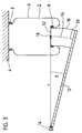
Figur 1 zeigt ein System 2, das einen Luftfederbalg 6 enthält, der zwischen einer Deckplatte
4 und einem Abrollkolben 10, beispielsweise mit Hilfe von Spannringen 8 eingespannt ist. Figure 1 shows a
Der Luftfederbalg 6 umschließt einen luftdicht abgeschlossenen Raum und bildet eine
Luftfeder 6. Der Abrollkolben 10 ist relativ zu dem Luftfederbalg 6 bewegbar angeordnet,
wobei die Bewegung des Abrollkolbens durch eine gekrümmte Bahn 16 vorgegeben ist. Im
Folgenden wird erläutert, was unter der Formulierung, daß
In der Figur 1 ist der Zustand gezeigt, in dem der Abrollkolben 10 ganz aus dem
Luftfederbalg 6 herausgezogen ist. In diesem Zustand wird ein festliegender Punkt 18
definiert, der im Zentrum der Abrollfalte 20 liegt und der den Anfangspunkt der gekrümmten
Bahn 16 bildet. In dem Punkt 18 weist die gekrümmte Bahn 16 einen Krümmungsradius r
auf, der einen Drehpunkt 22 festlegt. Der Krümmungsradius r wird auf der gekrümmten Bahn
16 noch über einen Winkel β beibehalten. Der Punkt 24 des Abrollkolbens 10, der in der
Figur 1 gezeigten Ausgangsposition mit dem Punkt 18 zusammenfällt, wird aus dieser
Ausgangslage um das Kreissegment rβ verdreht und der Abrollkolben 10 taucht in den
Luftfederbalg 6 ein. Dabei wird die gekrümmte Bahn 16
Die in der Figur 1 gezeigte gekrümmte Bahn 16 liegt vollständig in der Zeichenebene, dies
ist jedoch nicht notwendigerweise so. Vielmehr kann die gekrümmte Bahn 16 nahezu
beliebig aussehen. Der Verlauf der gekrümmten Bahn 16 wird allein dadurch bestimmt, wie
der Abrollkolben 10 gegenüber dem Luftfederbalg 6 gelagert ist. Die Bewegung des
Abrollkolbens ist festgelegt durch den Krümmungsradius der gekrümmten Bahn 16 und
durch den Winkelbereich, über den die gekrümmte Bahn diesen Krümmungsradius
beibehält.The
Bei dem in der Figur 1 gezeigten Beispiel ist der Abrollkolben 10 gekrümmt, wobei die
Krümmung des Abrollkolbens 10 zumindest bereichsweise die gleiche Orientierung hat wie
die Krümmung der gekrümmten Bahn 16. Dies ist zwischen den Punkten 24 und 26 der
gekrümmten Bahn 16 der Fall, wohingegen zwischen den Punkten 26 und 28 die
Orientierung der Krümmung des Abrollkolbens 10 der Orientierung der Krümmung der
gekrümmten Bahn 16 entgegengesetzt ist.In the example shown in Figure 1, the
Figur 2 zeigt ein System 2, enthaltend einen Luftfederbalg, der zwischen einer Deckplatte 4
und einem Abrollkolben 10, z. B. mit Hilfe von Spannringen 8, eingespannt ist. Der
Abrollkolben 10 ist auf einem Element 12, beispielsweise einem Längslenker, befestigt. Das
Element ist in einem Befestigungspunkt 14 drehbar gelagert, wobei bei dem in der Figur 2
gezeigten Beispiel die Drehachse im Punkt 14 senkrecht auf der Zeichenebene steht. Die
Figur 2 zeigt das System in dem Zustand, in dem der Abrollkolben 10 ganz aus dem
Luftfederbalg 6 herausgezogen ist. In diesem Zustand hat die gekrümmte Bahn 16 im Punkt
18 einen Krümmungsradius r, der durch den Abstand zwischen dem Punkt 14 und dem
Punkt 18 vorgegeben ist. Diesen Krümmungsradius r weist die gekrümmte Bahn 16 über
den gesamten Winkelbereich β auf. Der Abrollkolben 10 bewegt sich relativ zu dem
Luftfederbalg 6, einem Kreisbahnsegment, das durch den Radius r und durch den Winkel β
vorgegeben ist.FIG. 2 shows a
Bei dem in der Figur 2 gezeigten Ausführungsbeispiel ist der Abrollkolben so ausgebildet,
daß die mittlere Krümmungslinie 30 des Abrollkolbens 10 der gekrümmten Bahn 16 des
Abrollkolbens entspricht.In the embodiment shown in Figure 2, the rolling piston is designed so
that the central line of
Figur 3 zeigt ein System 2, das an sich genauso aufgebaut ist, wie das in der Figur 2
gezeigte System. Der einzige Unterschied ist darin zu sehen, daß der Abrollkolben 10 an
dem Ende 32, das der Deckplatte 4 zugewandt ist, eine Krümmung aufweist, dessen
Orientierung der Orientierung der gekrümmten Bahn 16 im Anfangsbereich entgegengesetzt
ist. Taucht der in der Figur 3 gezeigte Abrollkolben 10 so in den Luftfederbalg 6 ein, wie es
durch die gekrümmte Bahn 16 vorgegeben ist, so kommt es nicht so schnell zu einer
Berührung zwischen dem Abrollkolben 10 und dem Luftfederbalg 6 wie bei dem in der Figur
2 gezeigten System. Durch die Ausbildung des Abrollkolbens 10 gemäß der Figur 3 werden
also Freigangvorteile erzielt. FIG. 3 shows a
- 22nd
- Systemsystem
- 44th
- DeckplatteCover plate
- 66
- LuftfederbalgAir bag
- 88th
- SpannringTension ring
- 1010th
- AbrollkolbenRolling piston
- 1212th
- Elementelement
- 1414
- BefestigungspunktAttachment point
- 1616
- gekrümmte Bahncurved path
- 1818th
- PunktPoint
- 2020th
- AbrollfalteRoll fold
- 2222
- Drehpunktpivot point
- 2424th
- PunktPoint
- 2626
- PunktPoint
- 2828
- PunktPoint
- 3030th
- KrümmungslinieLine of curvature
- 3232
- EndeThe End
Claims (6)
der Abrollkolben (10) gekrümmt ist, wobei die Krümmung zumindest bereichsweise die gleiche Orientierung hat, wie die Krümmung der gekrümmten Bahn (16).System (2), which contains the following components:
the rolling piston (10) is curved, the curvature at least in some areas having the same orientation as the curvature of the curved path (16).
Applications Claiming Priority (2)
| Application Number | Priority Date | Filing Date | Title |
|---|---|---|---|
| DE19745415 | 1997-10-15 | ||
| DE19745415A DE19745415C2 (en) | 1997-10-15 | 1997-10-15 | System, comprising an air bellows and a rolling piston that moves on a curved path |
Publications (3)
| Publication Number | Publication Date |
|---|---|
| EP0909904A2 true EP0909904A2 (en) | 1999-04-21 |
| EP0909904A3 EP0909904A3 (en) | 2000-11-15 |
| EP0909904B1 EP0909904B1 (en) | 2005-02-09 |
Family
ID=7845542
Family Applications (1)
| Application Number | Title | Priority Date | Filing Date |
|---|---|---|---|
| EP98119043A Expired - Lifetime EP0909904B1 (en) | 1997-10-15 | 1998-10-08 | System containing a an air spring rolling lobe and an unrolling piston moving along a curved path |
Country Status (3)
| Country | Link |
|---|---|
| US (1) | US6173946B1 (en) |
| EP (1) | EP0909904B1 (en) |
| DE (2) | DE19745415C2 (en) |
Families Citing this family (4)
| Publication number | Priority date | Publication date | Assignee | Title |
|---|---|---|---|---|
| WO2002103218A1 (en) * | 2001-06-15 | 2002-12-27 | Phoenix Ag | Air-spring system |
| DE10221894B4 (en) * | 2002-05-16 | 2005-12-22 | Trelleborg Automotive Technical Centre Gmbh | Leveling Module |
| US12576680B2 (en) * | 2021-08-17 | 2026-03-17 | ILJIN USA Corporation | Synthetic elastomeric air spring without reinforcing fibers |
| AU2022334269B2 (en) * | 2021-08-27 | 2025-05-15 | Hendrickson Usa, L.L.C. | Damping air spring for heavy-duty vehicle axle/suspension systems |
Family Cites Families (5)
| Publication number | Priority date | Publication date | Assignee | Title |
|---|---|---|---|---|
| DE1048165B (en) * | 1957-02-20 | 1958-12-31 | Phoenix Gummiwerke Ag | Air springs, especially for motor vehicles |
| US4386791A (en) * | 1981-07-06 | 1983-06-07 | Ford Motor Company | Actively controlled suspension system and height sensor |
| JP2662218B2 (en) * | 1987-04-03 | 1997-10-08 | 株式会社ブリヂストン | Air spring |
| US4817922A (en) * | 1987-10-23 | 1989-04-04 | The Goodyear Tire & Rubber Company | Airspring height sensor |
| DE4201629C1 (en) * | 1992-01-22 | 1993-07-15 | Otto Sauer Achsenfabrik Keilberg, 8751 Bessenbach, De |
-
1997
- 1997-10-15 DE DE19745415A patent/DE19745415C2/en not_active Expired - Fee Related
-
1998
- 1998-10-08 DE DE59812551T patent/DE59812551D1/en not_active Expired - Lifetime
- 1998-10-08 EP EP98119043A patent/EP0909904B1/en not_active Expired - Lifetime
- 1998-10-09 US US09/168,893 patent/US6173946B1/en not_active Expired - Fee Related
Non-Patent Citations (1)
| Title |
|---|
| None |
Also Published As
| Publication number | Publication date |
|---|---|
| US6173946B1 (en) | 2001-01-16 |
| EP0909904A3 (en) | 2000-11-15 |
| EP0909904B1 (en) | 2005-02-09 |
| DE19745415C2 (en) | 2003-04-10 |
| DE59812551D1 (en) | 2005-03-17 |
| DE19745415A1 (en) | 1999-04-29 |
Similar Documents
| Publication | Publication Date | Title |
|---|---|---|
| EP1378382B1 (en) | Wheel suspension for a vehicle with a transverse leaf spring | |
| DE69908714T2 (en) | Coil compression spring for a vehicle wheel suspension | |
| EP2049815B1 (en) | Air spring for vehicles | |
| DE69200820T2 (en) | Fabric reinforced stiffeners for air springs. | |
| DE102013218055A1 (en) | Bearing device of a transverse leaf spring which is mountable in the region of a vehicle axle of a vehicle | |
| DE2063448A1 (en) | Suspension strut consisting of shock absorber and air spring | |
| EP1031756A2 (en) | Fastening of the rolling diaphragm of an air spring on a supporting member | |
| EP0626524A1 (en) | Pneumatically actuated floating caliper disc brake for commercial vehicles | |
| DE102007004035B4 (en) | Tubular rolling bellows and air spring | |
| EP0229940B1 (en) | Flexible support mounting for the cab of a heavy goods vehicle | |
| EP1935678A2 (en) | Wheel suspension | |
| DE4317510A1 (en) | Suspension system for motor vehicles | |
| EP0909904A2 (en) | System containing a an air spring rolling lobe and an unrolling piston moving along a curved path | |
| EP0656271A1 (en) | Pivot, especially for a steering rod of a motor vehicle | |
| DE102005015089B4 (en) | Suspension for a vehicle | |
| DE102016210074A1 (en) | Trailing arm for a suspension and suspension with trailing arm | |
| EP0916525A2 (en) | Wheel guiding device for a motor vehicle | |
| DE102015108484A1 (en) | Transverse leaf spring for a motor vehicle and axle assembly with a transverse leaf spring | |
| DE4244140C2 (en) | Swivel bearing | |
| DE10301660B4 (en) | Device for moving and rotating a vehicle sun visor | |
| DE10297691T5 (en) | Coil spring of the closed-end type, which has a reduced initial deflection | |
| EP1371872B1 (en) | Air spring arrangement | |
| DE102013113492B4 (en) | Device for lifting an air suspension lift axle and lifting axle device with such a device | |
| DE3438591A1 (en) | Coil spring, especially coil compression spring for motor vehicle wheel suspensions | |
| DE19809658A1 (en) | Pneumatic spring for e.g. private motor vehicle |
Legal Events
| Date | Code | Title | Description |
|---|---|---|---|
| PUAI | Public reference made under article 153(3) epc to a published international application that has entered the european phase |
Free format text: ORIGINAL CODE: 0009012 |
|
| AK | Designated contracting states |
Kind code of ref document: A2 Designated state(s): DE ES FR IT |
|
| AX | Request for extension of the european patent |
Free format text: AL;LT;LV;MK;RO;SI |
|
| PUAL | Search report despatched |
Free format text: ORIGINAL CODE: 0009013 |
|
| AK | Designated contracting states |
Kind code of ref document: A3 Designated state(s): AT BE CH CY DE DK ES FI FR GB GR IE IT LI LU MC NL PT SE |
|
| AX | Request for extension of the european patent |
Free format text: AL;LT;LV;MK;RO;SI |
|
| 17P | Request for examination filed |
Effective date: 20010515 |
|
| AKX | Designation fees paid |
Free format text: DE ES FR IT |
|
| 17Q | First examination report despatched |
Effective date: 20030604 |
|
| GRAP | Despatch of communication of intention to grant a patent |
Free format text: ORIGINAL CODE: EPIDOSNIGR1 |
|
| GRAS | Grant fee paid |
Free format text: ORIGINAL CODE: EPIDOSNIGR3 |
|
| GRAA | (expected) grant |
Free format text: ORIGINAL CODE: 0009210 |
|
| AK | Designated contracting states |
Kind code of ref document: B1 Designated state(s): DE ES FR IT |
|
| PG25 | Lapsed in a contracting state [announced via postgrant information from national office to epo] |
Ref country code: IT Free format text: LAPSE BECAUSE OF FAILURE TO SUBMIT A TRANSLATION OF THE DESCRIPTION OR TO PAY THE FEE WITHIN THE PRESCRIBED TIME-LIMIT;WARNING: LAPSES OF ITALIAN PATENTS WITH EFFECTIVE DATE BEFORE 2007 MAY HAVE OCCURRED AT ANY TIME BEFORE 2007. THE CORRECT EFFECTIVE DATE MAY BE DIFFERENT FROM THE ONE RECORDED. Effective date: 20050209 Ref country code: FR Free format text: LAPSE BECAUSE OF NON-PAYMENT OF DUE FEES Effective date: 20050209 |
|
| REF | Corresponds to: |
Ref document number: 59812551 Country of ref document: DE Date of ref document: 20050317 Kind code of ref document: P |
|
| PG25 | Lapsed in a contracting state [announced via postgrant information from national office to epo] |
Ref country code: ES Free format text: LAPSE BECAUSE OF FAILURE TO SUBMIT A TRANSLATION OF THE DESCRIPTION OR TO PAY THE FEE WITHIN THE PRESCRIBED TIME-LIMIT Effective date: 20050520 |
|
| PLBE | No opposition filed within time limit |
Free format text: ORIGINAL CODE: 0009261 |
|
| STAA | Information on the status of an ep patent application or granted ep patent |
Free format text: STATUS: NO OPPOSITION FILED WITHIN TIME LIMIT |
|
| 26N | No opposition filed |
Effective date: 20051110 |
|
| EN | Fr: translation not filed | ||
| PGFP | Annual fee paid to national office [announced via postgrant information from national office to epo] |
Ref country code: DE Payment date: 20091016 Year of fee payment: 12 |
|
| REG | Reference to a national code |
Ref country code: DE Ref legal event code: R119 Ref document number: 59812551 Country of ref document: DE Effective date: 20110502 |
|
| PG25 | Lapsed in a contracting state [announced via postgrant information from national office to epo] |
Ref country code: DE Free format text: LAPSE BECAUSE OF NON-PAYMENT OF DUE FEES Effective date: 20110502 |