EP0909248B1 - Breakable sachet - Google Patents
Breakable sachet Download PDFInfo
- Publication number
- EP0909248B1 EP0909248B1 EP96925190A EP96925190A EP0909248B1 EP 0909248 B1 EP0909248 B1 EP 0909248B1 EP 96925190 A EP96925190 A EP 96925190A EP 96925190 A EP96925190 A EP 96925190A EP 0909248 B1 EP0909248 B1 EP 0909248B1
- Authority
- EP
- European Patent Office
- Prior art keywords
- layer
- reservoir
- semi
- sachet
- rigid
- Prior art date
- Legal status (The legal status is an assumption and is not a legal conclusion. Google has not performed a legal analysis and makes no representation as to the accuracy of the status listed.)
- Expired - Lifetime
Links
Images


Classifications
-
- B—PERFORMING OPERATIONS; TRANSPORTING
- B65—CONVEYING; PACKING; STORING; HANDLING THIN OR FILAMENTARY MATERIAL
- B65B—MACHINES, APPARATUS OR DEVICES FOR, OR METHODS OF, PACKAGING ARTICLES OR MATERIALS; UNPACKING
- B65B9/00—Enclosing successive articles, or quantities of material, e.g. liquids or semiliquids, in flat, folded, or tubular webs of flexible sheet material; Subdividing filled flexible tubes to form packages
- B65B9/02—Enclosing successive articles, or quantities of material between opposed webs
-
- B—PERFORMING OPERATIONS; TRANSPORTING
- B65—CONVEYING; PACKING; STORING; HANDLING THIN OR FILAMENTARY MATERIAL
- B65D—CONTAINERS FOR STORAGE OR TRANSPORT OF ARTICLES OR MATERIALS, e.g. BAGS, BARRELS, BOTTLES, BOXES, CANS, CARTONS, CRATES, DRUMS, JARS, TANKS, HOPPERS, FORWARDING CONTAINERS; ACCESSORIES, CLOSURES, OR FITTINGS THEREFOR; PACKAGING ELEMENTS; PACKAGES
- B65D75/00—Packages comprising articles or materials partially or wholly enclosed in strips, sheets, blanks, tubes, or webs of flexible sheet material, e.g. in folded wrappers
- B65D75/52—Details
- B65D75/58—Opening or contents-removing devices added or incorporated during package manufacture
- B65D75/5827—Tear-lines provided in a wall portion
- B65D75/585—Tear-lines provided in a wall portion the tear-lines being broken by deformation or bending
Definitions
- the present invention relates to sachets. More particularly, although not exclusively, the present invention relates a sachet for storing and dispensing quantities of liquid, paste, powder or similar substances in discrete predetermined quantities. The present invention further relates to an apparatus and method for producing said sachets.
- the general area of application of the present invention is in the production and distribution of food condiments.
- other applications such as dispensing medicines, glues, cosmetics and the like are envisaged.
- Sachets known in the art include flexible sachets wherein the contents are expelled by, for example, tearing off a corner or end of the sachet and exerting pressure on the exterior of the sachet.
- One solution includes dividing the rigid tray into two sections and providing a perforated "beak" in a more substantial plastic or foil lid.
- the beak is located between the two tray sections wherein the tray sections in the beak are arranged so that when the ends of the condiment tray are bent towards each other in such a manner as to crush one section against another, the beak cracks along the aforesaid perforation and the contents may be expelled through the cracked beak by squeezing.
- This construction suffers from disadvantages in that the perforations sometimes crack in transit and the contents of the tray sections can spoil or be otherwise contaminated. They are also more complicated structurally and therefore more expensive to manufacture.
- a sachet for the storage and application of liquid/paste substances formed from a plurality of layers sandwiched together to form a reservoir wherein at least one of said layers is a semi-rigid plastics layer adapted so that upon bending said semi-rigid plastics layer will fracture along a region of weakness adapted to effect said fracture, said semi-rigid plastics layer is located so as to form an outside layer of said, the reservoir being located between the layer adjacent said semi-rigid plastics layer and a further layer, layers characterised in that the layer adjacent the semi-rigid layer incorporates an aperture located proximate and fracture.
- the sachet can be elongate, oval or similar suitable shape.
- the region of weakness can incorporate a score to effect the fracture.
- the reservoir can contain a liquid, paste, powder or similar substance.
- the reservoir can, with suitable adaptation contain a powder, granules or similar dry substance.
- the semi-rigid plastics layer may be smaller than the reservoir formed form the first and second flexible layers, the geometry of the layers being adapted so that the reservoir forms a flexible bag and the semi-rigid layer forms an opening means.
- the sachet is adapted so that when it is bent the semi-rigid layer fractures and upon further bending and subsequent compression of the reservoir contents, the liquid, paste or similar substance is forced through the aperture and out of the sachet.
- the liquid in the reservoir can be scented, an air freshener or slow release insect repellent or killer.
- the present invention provides for a method of manufacturing sachets as described above including sandwiching two layers and one semi-rigid plastics layer together in such a way as to form a continuous elongate reservoir between the layer adjacent the semi-rigid plastics layer and a further layer, wherein the layer adjacent the semi-rigid layer has apertures formed therein prior to forming said continuous reservoir; the reservoir is filled with a liquid, paste or similar substance and the filled reservoir fed continuously through a hot roller, the hot roller being adapted to seal the continuous reservoir substantially perpendicular to the elongate direction of said continuous reservoir and in such a manner as to form discrete reservoirs corresponding to each sachet reservoir wherein fracture lines or scores are formed in the semi-rigid layer either during manufacture or preformed in the semi-rigid layer.
- the semi-rigid layer and the adjacent layer are pre-laminated prior to the addition of any further layers.
- the fracture line or score has dimensions such that the semi-rigid layer fractures in a region proximate the hole in the layer.
- the continuous reservoir is orientated substantially vertically and filled using delivery means having an outlet located in the continuous reservoir formed between the two layers.
- the plurality of layers can be sealed by heat, heat activated glue or similar means.
- the sachet is made up of three plastics layers 11, 12 and 13.
- Layer 11 corresponds to the semi-rigid plastics layer and layers 12 and 13 correspond to the flexible plastics layers which between them form the reservoir which contains the liquid, paste, or similar substance indicated in outline by 19.
- the thickness of the layers have been exaggerated in Figures 1 to 4.
- the layers 12 and 13 will be plastics films and the semi-rigid layer 11 will be approximately 0.5mm thick.
- the semi-rigid plastics layer 11 incorporates a transverse "score" 15. This is to provide a predictable fracture line so that when the ends 17 and 18 of the sachet are drawn together the reservoir 14 may be compressed between the two halves.
- the transverse score 15 acts as a weak point and the semi-rigid plastic layer 11 will fracture cleanly along that line, thereby providing a fracture region.
- the orientation of the fracture line is not restricted to transverse and other configurations are envisaged such as diagonal or offset from the centre.
- the fracture need not form a straight edge. Depending on the particular application, a curved, diagonal or serrated edge may be suitable.
- transverse score is shown extending completely across the sachet, it may stop short of the edges and therefore provide a weak point primarily in the region near the hole. This avoids the possibility of sharp edge being produced at the edge of the broken semi-rigid layer pieces.
- the hole 16 is located in layer 13 proximate the transverse score 15.
- the aperture is an oval hole 16.
- the hole could be in the form of a slit or other shape, and aligned with the transverse score. Such variations are considered within the scope of the present invention.
- the configuration of the particular example described herein is particularly advantageous in that upon drawing the ends 17 and 18 together the score is fractured and the substance contained within the reservoir 14 may be then extruded or forced through the hole 16 in a controlled manner. Further the edge formed by the transverse score 15 may be used to spread the substance or distribute it onto the article as desired. It is considered that this provides more control over where or how the substance in reservoir 14 may be spread or deposited than the prior art devices and further does not require the use of a separate spreading implement.
- the present example has been described with reference to an elongate sachet, it is envisaged that other shapes are possible such as oval, circular or the like.
- the present invention could equally be used in the application of medical substances such as antiseptics, burn treatments and the like.
- the present invention could additionally have an absorbent layer located proximate the exit aperture and extend over the exposed surface of layer 11 as desired.
- the absorbent layer could further be covered by a sterile protective strip which may be torn off to expose the absorbent layer.
- the sachet could be constructed so that the reservoir is significantly larger than the semi-rigid layer.
- the rigid layer and fracture would act more as an opening means for a larger reservoir. It is envisaged that volumes of 1 to 2 litres could be accommodated by such a construction and the breakable part of the sachet be located conveniently on the wall of the reservoir so that upon bending the fracture is formed and the enclosed substance extracted by squeezing the reservoir.
- the reservoir shape need not be limited to elongate or oval.
- the reservoir may be formed so as to be in a distinctive shape such as a well known bottle outline or similar recognisable outline.
- FIG. 5 an apparatus for the manufacture of the sachets is shown.
- One novel aspect of the process resides in the method of forming each of the sachet reservoirs.
- the particular example shown is for the manufacture of sachets including a single semi-rigid layer and two flexible plastics layers as described above wherein the two flexible plastics layers form the reservoir for containing the substance.
- the layers are fed from continuous rolls 21, 26 and 25.
- the middle layer 31 has an aperture formed therein by means of a device 24.
- a device may operate by melting, punching or a similar technique known in the art.
- the spacing and location of the holes is calculated based on the sachet dimensions and the location of the fracture point or "score" in the semi-rigid layer.
- the fracture point may be preformed in the semi-rigid layer or formed during the manufacture process.
- the score may be smaller than the width of the sachet, thus providing a different fracture characteristic.
- the layers 31 and 33 could alternatively be pre-laminated and then fed into the roller system at roller 35 where the sachet contents is injected.
- Layers 31 and 33 are continuously fed to heated rollers 22 and 23 wherein they are thermally bonded together.
- Layer 32 is continuously fed to heated rollers 34 and 35 where layer 32 is thermally bonded to a continuous portion of the surface of layer 31.
- Heated roller 34 is shaped so that upon continuous movement of the layers through the rollers only the edges of the layer 32 are bonded to the aforementioned layers so that a lengthwise continuous reservoir is formed from below the heated rollers 34 and 35.
- roller 35 is "dumbbell" shaped with the edges locating adjacent roller 35 sealing the layers together at their edges.
- the heat sealing step may be repeated to ensure effective closure. It is possible that in the initial heating step, the 'squeezing' of the contents away from the sealing zone may conduct heat away thus producing an imperfect seal. The subsequent sealing step is intended to address this potential difficulty.
- a delivery tube 28 is located in such a manner so that it extends between rollers 34 and 35 through the space formed by the shape of the roller 34.
- the delivery tube 28 extends downwards substantially into the continuous reservoir.
- Fluid for example, is continuously supplied to the delivery system 28 so as to fill the continuous reservoir up to a constant level. This has the added advantage of excluding air from the reservoir to reduce the possibility of reaction or deterioration of the fluid contained therein.
- the fluid filled continuous reservoir then travels through heated rollers 29 and 27 wherein heated elements 30 compress the layer 32 against roller 27 thereby forcing the liquid out of the contact region 37 and thermally bonding the layer 32 to the layer 31 (which is already bonded to semi-rigid layer 33).
- a variation of the present sachet includes a further sealing step whereby a strip of layer 12 and 13 is bonded together along the line of the fracture line. Such a bonded strip would divide the reservoir into two components with communication possible via the hole 16. Such a configuration may allow improved control when the contents is squeezed out of the reservoirs.
- the substance to be contained in the reservoir may be simply dropped onto the top surface of layer 32. This technique is suitable for particularly viscous substances.
- roller 34 may be shaped so as to form a plurality of continuous reservoirs running vertically parallel through the roller system. In this case a number of delivery tubes 28 will be required.
- This alternative embodiment is considered within the scope of the invention.
- a further variation uses a divider wheel which separates the reservoir into two vertically oriented reservoirs.
- the web of sachets produced may be subsequently fed into a cutting machine or transported in a roll for further processing.
- the substance fed through delivery system 28 may be liquid or paste or similar, and may be fed under pressure or by gravity feed.
- the feed rate may be regulated so as to maintain a constant head of liquid in the continuous reservoir region above the heated rollers 29 and 27 so as to exclude air from the sachet reservoir.
- a further advantage of the present invention is that layers 31, 32 or 33 may have preprinted material on them with the semi-rigid layer providing a particularly useful surface on which to place identify, decorative or similar graphical material.
- the manufacturing system shown in Figure 5 may also include perforating rollers (not shown) which provide perforations between the sachet elements 10. In this configuration webs of sachets may be delivered in a roll and broken off by hand as required.
- the apparatus shown in Figure 5 may be further adapted to include different numbers of layers depending on the construction of the sachet required and the nature of the substance to be contained therein. Further, there may be more than one separate reservoir in each sachet unit. Such variations may include a plurality of holes associated with a specific reservoir. This would allow for mixing of, for example, two substances such as glues comprising a bonding agent and activator.
- a convenient sachet for use in dispensing, for example, foodstuffs in the form of liquid, paste or similar.
- the sachet may be also used for dispensing medical substances wherein the apparatus in Figure 5 operates in a sterile environment.
- the sachets are convenient and clean. Trial and experimentation have found that the sachets are resistant to puncturing and cracking along the transverse score 15 as well as to pressure exerted on the reservoir.
- the sachets may be manufactured in convenient sizes, the dimensions and shape of which allow for easy storage, transport and display (in retail situations).
- the sachets are also particularly suitable for distribution from a dispensing device.
- the apparatus of Figure 5 may also be readily modified whereby the height of the heated elements 30 and the depth of the heated roller 34 (shown by dotted line 36) may be varied to allow for a range of reservoir volumes.
Landscapes
- Engineering & Computer Science (AREA)
- Mechanical Engineering (AREA)
- Packages (AREA)
- Bag Frames (AREA)
- Package Closures (AREA)
- Gyroscopes (AREA)
- Semiconductor Lasers (AREA)
- Containers And Plastic Fillers For Packaging (AREA)
Abstract
Description
- The present invention relates to sachets. More particularly, although not exclusively, the present invention relates a sachet for storing and dispensing quantities of liquid, paste, powder or similar substances in discrete predetermined quantities. The present invention further relates to an apparatus and method for producing said sachets.
- The general area of application of the present invention is in the production and distribution of food condiments. However, other applications such as dispensing medicines, glues, cosmetics and the like are envisaged.
- Sachets known in the art include flexible sachets wherein the contents are expelled by, for example, tearing off a corner or end of the sachet and exerting pressure on the exterior of the sachet.
- Other prior art devices include rigid moulded "tray" or "blister" type sachets wherein the condiment or similar substance is sealed in by means of an aluminium foil or plastic lid. The lid is heat-sealed or otherwise secured to the upper edges of the tray. In this case the contents are extracted by peeling back the foil lid and either exerting pressure on the lid and the plastic tray or by using an implement such as a knife or spoon to extract the contents.
- These constructions suffer disadvantages in that they can be expensive to manufacture, messy to use and, when extracting the contents of the sachet, behave unpredictably in terms of the flow of the substance through, for example, the aperture formed by tearing off the comer of the sachet. In the case of the tear-back foil lid the mobility and ease of extraction of the contents may vary depending on the viscosity of the contents.
- There have been attempts to overcome these disadvantages in the prior art, however, they have met with mixed success. One solution includes dividing the rigid tray into two sections and providing a perforated "beak" in a more substantial plastic or foil lid. The beak is located between the two tray sections wherein the tray sections in the beak are arranged so that when the ends of the condiment tray are bent towards each other in such a manner as to crush one section against another, the beak cracks along the aforesaid perforation and the contents may be expelled through the cracked beak by squeezing. This construction suffers from disadvantages in that the perforations sometimes crack in transit and the contents of the tray sections can spoil or be otherwise contaminated. They are also more complicated structurally and therefore more expensive to manufacture.
- An example of this type of package can be found in AU 47827/85, which corresponds to the preamble of appended
claim 1. This discloses a package with two pockets. These are bent towards one another, breaching a fault line on the outer sealed layer, thus releasing the contents. - It is an object of the present invention to provide a sachet and a means and method of producing the same, which overcomes or at least mitigates the above mentioned disadvantages, or at least provides the public with a useful choice.
- According to one aspect of the invention there is provided a sachet for the storage and application of liquid/paste substances formed from a plurality of layers sandwiched together to form a reservoir wherein at least one of said layers is a semi-rigid plastics layer adapted so that upon bending said semi-rigid plastics layer will fracture along a region of weakness adapted to effect said fracture, said semi-rigid plastics layer is located so as to form an outside layer of said, the reservoir being located between the layer adjacent said semi-rigid plastics layer and a further layer, layers characterised in that the layer adjacent the semi-rigid layer incorporates an aperture located proximate and fracture.
- The sachet can be elongate, oval or similar suitable shape.
- The region of weakness can incorporate a score to effect the fracture.
- The reservoir can contain a liquid, paste, powder or similar substance.
- The reservoir can, with suitable adaptation contain a powder, granules or similar dry substance.
- In an alternative embodiment, the semi-rigid plastics layer may be smaller than the reservoir formed form the first and second flexible layers, the geometry of the layers being adapted so that the reservoir forms a flexible bag and the semi-rigid layer forms an opening means.
- In use, the sachet is adapted so that when it is bent the semi-rigid layer fractures and upon further bending and subsequent compression of the reservoir contents, the liquid, paste or similar substance is forced through the aperture and out of the sachet.
- The liquid in the reservoir can be scented, an air freshener or slow release insect repellent or killer.
- In a further aspect the present invention provides for a method of manufacturing sachets as described above including sandwiching two layers and one semi-rigid plastics layer together in such a way as to form a continuous elongate reservoir between the layer adjacent the semi-rigid plastics layer and a further layer, wherein the layer adjacent the semi-rigid layer has apertures formed therein prior to forming said continuous reservoir; the reservoir is filled with a liquid, paste or similar substance and the filled reservoir fed continuously through a hot roller, the hot roller being adapted to seal the continuous reservoir substantially perpendicular to the elongate direction of said continuous reservoir and in such a manner as to form discrete reservoirs corresponding to each sachet reservoir wherein fracture lines or scores are formed in the semi-rigid layer either during manufacture or preformed in the semi-rigid layer.
- Preferably the semi-rigid layer and the adjacent layer are pre-laminated prior to the addition of any further layers.
- Preferably, the fracture line or score has dimensions such that the semi-rigid layer fractures in a region proximate the hole in the layer.
- Preferably the continuous reservoir is orientated substantially vertically and filled using delivery means having an outlet located in the continuous reservoir formed between the two layers.
- The plurality of layers can be sealed by heat, heat activated glue or similar means.
- Further objects and advantages will become apparent in the following description which will be by way of example only and with reference to the accompanying drawings.
-
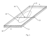
- Figure 1
- illustrates a perspective view of a sachet;
- Figure 2
- shows a section through the sachet along line A-A;
- Figure 3
- illustrates the sachet through the section A-A when the contents are being extracted;
- Figure 4
- illustrates an exploded view of section A-A; and
- Figure 5
- illustrates a schematic of an apparatus for manufacturing the sachets.
- In the example shown in Figures 1 to 4 the sachet is made up of three
plastics layers Layer 11 corresponds to the semi-rigid plastics layer andlayers - For clarity, the thickness of the layers have been exaggerated in Figures 1 to 4. In practice the
layers semi-rigid layer 11 will be approximately 0.5mm thick. - It is to be understood that variations in these thicknesses are within the scope of one skilled in the art and the present example is not to be construed restrictively.
- Referring to Figure 2, the
semi-rigid plastics layer 11 incorporates a transverse "score" 15. This is to provide a predictable fracture line so that when theends reservoir 14 may be compressed between the two halves. Thetransverse score 15 acts as a weak point and the semi-rigidplastic layer 11 will fracture cleanly along that line, thereby providing a fracture region. The orientation of the fracture line is not restricted to transverse and other configurations are envisaged such as diagonal or offset from the centre. The fracture need not form a straight edge. Depending on the particular application, a curved, diagonal or serrated edge may be suitable. Also, while the transverse score is shown extending completely across the sachet, it may stop short of the edges and therefore provide a weak point primarily in the region near the hole. This avoids the possibility of sharp edge being produced at the edge of the broken semi-rigid layer pieces. - Referring again to the embodiment including the centre layer, when the
ends reservoir 14 is compressed and the liquid orpaste 19 contained therein is forced out of thehole 16 and onto the article desired (food etc.). - The
hole 16 is located inlayer 13 proximate thetransverse score 15. In this particular example, the aperture is anoval hole 16. Alternatively, the hole could be in the form of a slit or other shape, and aligned with the transverse score. Such variations are considered within the scope of the present invention. - The configuration of the particular example described herein is particularly advantageous in that upon drawing the
ends reservoir 14 may be then extruded or forced through thehole 16 in a controlled manner. Further the edge formed by thetransverse score 15 may be used to spread the substance or distribute it onto the article as desired. It is considered that this provides more control over where or how the substance inreservoir 14 may be spread or deposited than the prior art devices and further does not require the use of a separate spreading implement. - While the present example has been described with reference to an elongate sachet, it is envisaged that other shapes are possible such as oval, circular or the like. Also, while the particular example has been described with reference to a condiment or liquid substance for use with foodstuffs, the present invention could equally be used in the application of medical substances such as antiseptics, burn treatments and the like. In this application, the present invention could additionally have an absorbent layer located proximate the exit aperture and extend over the exposed surface of
layer 11 as desired. The absorbent layer could further be covered by a sterile protective strip which may be torn off to expose the absorbent layer. - Further, the sachet could be constructed so that the reservoir is significantly larger than the semi-rigid layer. In this alternative embodiment, the rigid layer and fracture would act more as an opening means for a larger reservoir. It is envisaged that volumes of 1 to 2 litres could be accommodated by such a construction and the breakable part of the sachet be located conveniently on the wall of the reservoir so that upon bending the fracture is formed and the enclosed substance extracted by squeezing the reservoir.
- Further, the reservoir shape need not be limited to elongate or oval. The reservoir may be formed so as to be in a distinctive shape such as a well known bottle outline or similar recognisable outline.
- Referring to Figure 5 an apparatus for the manufacture of the sachets is shown. One novel aspect of the process resides in the method of forming each of the sachet reservoirs. The particular example shown is for the manufacture of sachets including a single semi-rigid layer and two flexible plastics layers as described above wherein the two flexible plastics layers form the reservoir for containing the substance. The layers are fed from
continuous rolls middle layer 31 has an aperture formed therein by means of adevice 24. Such a device may operate by melting, punching or a similar technique known in the art. The spacing and location of the holes is calculated based on the sachet dimensions and the location of the fracture point or "score" in the semi-rigid layer. The fracture point may be preformed in the semi-rigid layer or formed during the manufacture process. As discussed above, the score may be smaller than the width of the sachet, thus providing a different fracture characteristic. - The
layers roller 35 where the sachet contents is injected. -
Layers heated rollers 22 and 23 wherein they are thermally bonded together.Layer 32 is continuously fed toheated rollers layer 32 is thermally bonded to a continuous portion of the surface oflayer 31.Heated roller 34 is shaped so that upon continuous movement of the layers through the rollers only the edges of thelayer 32 are bonded to the aforementioned layers so that a lengthwise continuous reservoir is formed from below theheated rollers roller 35 is "dumbbell" shaped with the edges locatingadjacent roller 35 sealing the layers together at their edges. The heat sealing step may be repeated to ensure effective closure. It is possible that in the initial heating step, the 'squeezing' of the contents away from the sealing zone may conduct heat away thus producing an imperfect seal. The subsequent sealing step is intended to address this potential difficulty. - A
delivery tube 28 is located in such a manner so that it extends betweenrollers roller 34. Thedelivery tube 28 extends downwards substantially into the continuous reservoir. Fluid, for example, is continuously supplied to thedelivery system 28 so as to fill the continuous reservoir up to a constant level. This has the added advantage of excluding air from the reservoir to reduce the possibility of reaction or deterioration of the fluid contained therein. The fluid filled continuous reservoir then travels throughheated rollers heated elements 30 compress thelayer 32 againstroller 27 thereby forcing the liquid out of the contact region 37 and thermally bonding thelayer 32 to the layer 31 (which is already bonded to semi-rigid layer 33). - A variation of the present sachet includes a further sealing step whereby a strip of
layer hole 16. Such a configuration may allow improved control when the contents is squeezed out of the reservoirs. - In a further embodiment, the substance to be contained in the reservoir may be simply dropped onto the top surface of
layer 32. This technique is suitable for particularly viscous substances. - It is to be appreciated that the present description describes a single vertical continuous reservoir arrangement. However for different layer widths,
roller 34 may be shaped so as to form a plurality of continuous reservoirs running vertically parallel through the roller system. In this case a number ofdelivery tubes 28 will be required. This alternative embodiment is considered within the scope of the invention. A further variation uses a divider wheel which separates the reservoir into two vertically oriented reservoirs. - The web of sachets produced may be subsequently fed into a cutting machine or transported in a roll for further processing.
- The substance fed through
delivery system 28 may be liquid or paste or similar, and may be fed under pressure or by gravity feed. The feed rate may be regulated so as to maintain a constant head of liquid in the continuous reservoir region above theheated rollers - A further advantage of the present invention is that layers 31, 32 or 33 may have preprinted material on them with the semi-rigid layer providing a particularly useful surface on which to place identify, decorative or similar graphical material. The manufacturing system shown in Figure 5 may also include perforating rollers (not shown) which provide perforations between the sachet elements 10. In this configuration webs of sachets may be delivered in a roll and broken off by hand as required.
- While the present apparatus and sachet has been described in the context of plastics films and layers, it is envisaged that under certain circumstances paper layers or combinations of paper and plastics may be used, depending on the substance to be contained within the sachet and/or the tolerance of the substance to the bonding temperature. Such variations are considered within the scope of the present invention.
- The apparatus shown in Figure 5 may be further adapted to include different numbers of layers depending on the construction of the sachet required and the nature of the substance to be contained therein. Further, there may be more than one separate reservoir in each sachet unit. Such variations may include a plurality of holes associated with a specific reservoir. This would allow for mixing of, for example, two substances such as glues comprising a bonding agent and activator.
- Thus by the invention there is provided a convenient sachet for use in dispensing, for example, foodstuffs in the form of liquid, paste or similar. The sachet may be also used for dispensing medical substances wherein the apparatus in Figure 5 operates in a sterile environment.
- In use the sachets are convenient and clean. Trial and experimentation have found that the sachets are resistant to puncturing and cracking along the
transverse score 15 as well as to pressure exerted on the reservoir. - The sachets may be manufactured in convenient sizes, the dimensions and shape of which allow for easy storage, transport and display (in retail situations). The sachets are also particularly suitable for distribution from a dispensing device.
- The apparatus of Figure 5 may also be readily modified whereby the height of the
heated elements 30 and the depth of the heated roller 34 (shown by dotted line 36) may be varied to allow for a range of reservoir volumes.
Claims (10)
- A sachet for the storage and application of liquid/paste substances formed from a plurality of layers (11-13) sandwiched together to form a reservoir (14) wherein at least one of said layers is a semi-rigid plastics layer (11) adapted so that upon bending said semi-rigid plastics layer (11) will fracture along a region of weakness (15) adapted to effect said fracture, said semi-rigid plastics layer (11) is located so as to form an outside layer of said layers (11-13), the reservoir being located between the layer (13) adjacent said semi-rigid plastics layer (11) and a further layer (12), characterised in that the layer (13) adjacent the semi-rigid layer (11) incorporates an aperture (16) located proximate said fracture (15).
- A sachet as claimed in claim 1 wherein the sachet is elongate, oval or similar suitable shape.
- A sachet as claimed in any preceding claim wherein the region of weakness (15) incorporates a score to effect the fracture.
- A sachet as claimed in any preceding claim wherein the reservoir (14) contains a liquid, paste, powder or similar substance (19).
- A sachet as claimed in claim 1 or 2 wherein the semi-rigid layer (11) is smaller than the reservoir (14) formed from the first and second flexible layer (12,13), the geometry of the plastics layer (11) is adapted so that the reservoir (14) forms a flexible bag (19) and the semi-rigid layer (11) constitutes an opening means.
- A method of expelling the contents of a sachet wherein the sachet, as claimed in any previous claim, is adapted so that when it is bent the semi-rigid layer (11) fractures and upon further bending and subsequent compression of the reservoir (14) contents, the liquid, paste or similar substance (19) is forced through the aperture (16) and out of the sachet.
- A method of manufacturing sachets according to claim 1 including sandwiching two layers (12, 13) and one semi-rigid plastics layer (11) together in such as way as to form a continuous elongate reservoir between the layer (13) adjacent said semi-rigid plastics layer (11) and a further layer (12), wherein the layer (13) adjacent the semi-rigid layer (11) has apertures (16) formed therein prior to forming said continuous reservoir; the reservoir is filled with a liquid, paste or similar substance (19) and the filled reservoir fed continuously through a hot roller (22, 23), the hot roller (22, 23) being adapted to seal the continuous reservoir substantially perpendicular to the elongate direction of said continuous reservoir and in such a manner as to form discrete reservoirs (14) corresponding to each sachet reservoir (14) wherein fracture lines or scores (15) are formed in the semi-rigid layer (11) either during manufacture or preformed in the semi-rigid layer (11).
- A method of manufacturing a sachet as claimed in claim 7 wherein the semirigid layer (11) and the adjacent layer (12, 13) are pre-laminated prior to the addition of any further layers.
- A method of manufacturing a sachet as claimed in either of claims 7 or 8 wherein the continuous reservoir is oriented substantially vertically and filled using delivery means (28) having an outlet located in the continuous reservoir formed between the two layers (12, 13).
- A method of manufacturing a sachet as claimed in any one of claims 7 to 9 wherein the plurality of layers (11-13) is sealed by heat, heat activated glue or similar means.
Applications Claiming Priority (3)
| Application Number | Priority Date | Filing Date | Title |
|---|---|---|---|
| NZ27271895 | 1995-08-04 | ||
| NZ27271895 | 1995-08-04 | ||
| PCT/NZ1996/000078 WO1997006073A1 (en) | 1995-08-04 | 1996-07-26 | Breakable sachet |
Publications (3)
| Publication Number | Publication Date |
|---|---|
| EP0909248A1 EP0909248A1 (en) | 1999-04-21 |
| EP0909248A4 EP0909248A4 (en) | 1999-04-28 |
| EP0909248B1 true EP0909248B1 (en) | 2002-04-10 |
Family
ID=19925372
Family Applications (1)
| Application Number | Title | Priority Date | Filing Date |
|---|---|---|---|
| EP96925190A Expired - Lifetime EP0909248B1 (en) | 1995-08-04 | 1996-07-26 | Breakable sachet |
Country Status (9)
| Country | Link |
|---|---|
| US (1) | US6041930A (en) |
| EP (1) | EP0909248B1 (en) |
| JP (2) | JP3846637B2 (en) |
| CN (1) | CN1196709A (en) |
| AT (1) | ATE215900T1 (en) |
| AU (1) | AU714064B2 (en) |
| DE (1) | DE69620644T2 (en) |
| NZ (1) | NZ313329A (en) |
| WO (1) | WO1997006073A1 (en) |
Families Citing this family (58)
| Publication number | Priority date | Publication date | Assignee | Title |
|---|---|---|---|---|
| ATE236796T1 (en) * | 1997-04-10 | 2003-04-15 | Stephane Christopher Martel | DEVICE FOR THE DOSAGED DIFFUSION OF ONE OR MORE FLOWING MEDIA |
| FR2762490B1 (en) * | 1997-04-29 | 1999-07-02 | Stephan Christopher Martell | DEVICE FOR EXPLODING A COSMETIC OR PHARMACEUTICAL PRODUCT |
| FR2763224B1 (en) * | 1997-05-14 | 1999-07-16 | Martell Stephan Christopher | DEVICE FOR EXPLODING A COSMETIC OR PERFUMERY PRODUCT |
| US7121409B1 (en) | 1999-09-02 | 2006-10-17 | Snap Pak Industries (Aust) Pty Ltd. | Dispensing sachet by bending and method of sachet manufacture |
| AUPQ261599A0 (en) * | 1999-09-02 | 1999-09-23 | Snap Pak Industries (Aust) Pty Ltd | A sachet |
| FR2801179B1 (en) * | 1999-11-23 | 2002-08-30 | Delviel | METHOD OF ENCAPSULATING A TOPICAL COMPOSITION |
| AU779865B2 (en) * | 1999-12-14 | 2005-02-17 | Flexi-Pac (Proprietary) Limited | Containers and method for manufacturing containers |
| US6716498B2 (en) * | 1999-12-21 | 2004-04-06 | The Procter & Gamble Company | Applications for substance encapsulating laminate web |
| KR100700482B1 (en) * | 2000-06-19 | 2007-03-28 | 소른톤 트러스티 컴퍼니 리미티드 | Package for containing a flowable substance |
| FR2835816B1 (en) * | 2002-02-13 | 2004-07-16 | Valerie Delas | LIQUID PRODUCT DISTRIBUTOR AND APPLICATOR |
| US20050047846A1 (en) * | 2003-08-28 | 2005-03-03 | Closure Medical Corporation | Single-use applicators for adhesive material, packaging systems, methods of use and methods of manufacture |
| US20100065582A1 (en) * | 2003-12-02 | 2010-03-18 | The Tapemark Company | Dispensing package |
| US7506762B2 (en) * | 2003-12-02 | 2009-03-24 | The Tapemark Company | Dispensing package |
| AU2004100000A4 (en) * | 2004-01-02 | 2004-02-12 | Sands Innovations Pty Ltd | Dispensing stirring implement |
| EP1818307B1 (en) * | 2004-11-30 | 2015-01-14 | Mitsubishi Denki Kabushiki Kaisha | Device and method for repairing moving handrail of passenger conveyor |
| DE202005015085U1 (en) * | 2005-09-28 | 2005-12-01 | Klocke Verpackungs-Service Gmbh | Packing has rigid insert between second film and applicator extending beyond intended break point opposite it by such degree that with breaking open of packing the medium applicator is extracted from chamber |
| MX2009002954A (en) * | 2006-09-26 | 2009-03-31 | Cadbury Adams Usa Llc | Rupturable blister package. |
| US9216850B2 (en) | 2006-09-26 | 2015-12-22 | Intercontinental Great Brands Llc | Rupturable substrate |
| ITBO20060665A1 (en) * | 2006-09-28 | 2008-03-29 | Easypack Solutions S R L | SINGLE-DOSE SEALED PACKAGE WITH BREAK OPENING |
| KR101348326B1 (en) * | 2006-09-28 | 2014-01-06 | 디아팩 리미티드 | Sealed single-dose break-open package |
| WO2008083209A2 (en) * | 2006-12-29 | 2008-07-10 | Amir Genosar | Hypodermic drug delivery reservoir and apparatus |
| CN101600633A (en) * | 2007-01-31 | 2009-12-09 | 桑德斯创新有限公司 | Dispensing utensil and manufacture method thereof |
| ATE479606T1 (en) * | 2007-09-17 | 2010-09-15 | Tapemark Company | DISPLAY PACK WITH APPLICATOR |
| WO2009040629A2 (en) * | 2007-09-24 | 2009-04-02 | Diapack Limited | Break-open single-dose sealed package |
| EP2067710B1 (en) * | 2007-12-05 | 2014-03-26 | The Procter & Gamble Company | Recloseable Bag |
| US8663188B2 (en) | 2007-12-28 | 2014-03-04 | Aktivpak, Inc. | Dispenser and therapeutic package suitable for administering a therapeutic substance to a subject, along with method relating to same |
| US20090236254A1 (en) * | 2008-03-20 | 2009-09-24 | Jenkins Shawn E | Accessible Hand Hygiene System |
| ES2423288T3 (en) * | 2008-05-22 | 2013-09-19 | Wm. Wrigley Jr. Company | Blister container cover with notch formed by dual laser |
| US7954747B2 (en) * | 2008-06-13 | 2011-06-07 | Chudy Group, LLC | Pouch package spooler and method of pouch package web management |
| JP2011524206A (en) * | 2008-06-13 | 2011-09-01 | ヒル−ロム サービシーズ,インコーポレイティド | Bedside article support apparatus and system |
| CN102292270B (en) | 2008-12-09 | 2014-04-16 | 桑德斯创新有限公司 | A dispensing container |
| US8388248B2 (en) * | 2008-12-30 | 2013-03-05 | Kimberly-Clark Worldwide, Inc. | Medical liquid applicator system |
| US20110010854A1 (en) * | 2009-07-15 | 2011-01-20 | Zerhusen Robert M | Siderail with storage area |
| WO2011088176A1 (en) * | 2010-01-14 | 2011-07-21 | The Procter & Gamble Company | Method for treating a stained fabric |
| CA2690279C (en) | 2010-01-14 | 2013-11-12 | The Procter & Gamble Company | Apparatus for treating a stain in clothing |
| US8425136B2 (en) * | 2010-01-14 | 2013-04-23 | The Procter & Gamble Company | Apparatus for treating a stain in clothing |
| CA2690296C (en) * | 2010-01-14 | 2014-07-22 | The Procter & Gamble Company | Apparatus for treating a stain in clothing |
| US8511500B2 (en) | 2010-06-07 | 2013-08-20 | Sands Innovations Pty. Ltd. | Dispensing container |
| FR2971770B1 (en) * | 2011-02-21 | 2013-03-22 | Eric Noel | PACKAGED INTERNAL POCKET WITH A BREAKING MEANS |
| US8485360B2 (en) | 2011-03-04 | 2013-07-16 | Sands Innovations Pty, Ltd. | Fracturable container |
| ITMO20110258A1 (en) * | 2011-10-11 | 2013-04-12 | Mepar Societa A Responsabilita Li Mitata | SINGLE-DOSE SEALED PACKAGE WITH BREAKING OPENING AND METHOD FOR THE CREATION OF A SINGLE-DOSE SEALED PACKAGE WITH BREAKING OPENING |
| CA2946697C (en) * | 2014-04-30 | 2022-03-01 | Easysnap Technology S.R.L. | Sealed single-dose break-open package suited to be opened vertically |
| WO2016122479A1 (en) | 2015-01-28 | 2016-08-04 | Kimberly-Clark Worldwide, Inc. | Easy open package |
| JP5858413B1 (en) | 2015-01-30 | 2016-02-10 | 橋本 忠 | Peeling and opening packaging body, and opening structure of peeling and opening packaging body |
| KR101779326B1 (en) | 2015-05-27 | 2017-09-27 | 티에스케이 주식회사 | Pouch Manufacturing Device for Easy Exhaust Line Formation |
| US10159823B2 (en) | 2015-06-26 | 2018-12-25 | C. R. Bard, Inc. | Topical substance application device including applicator |
| JP6030266B1 (en) * | 2016-08-03 | 2016-11-24 | 株式会社フューチャーラボ | Manufacturing method and manufacturing apparatus for folded open package |
| JP6624741B2 (en) * | 2017-03-30 | 2019-12-25 | 株式会社フューチャーラボ | Fold open packaging |
| JP6611265B2 (en) * | 2017-03-30 | 2019-11-27 | 株式会社フューチャーラボ | Folded package |
| CA3059470A1 (en) | 2017-04-11 | 2018-10-18 | Sands Innovations Ltd | Fracturable container |
| CN107472677A (en) * | 2017-09-08 | 2017-12-15 | 四川汇利实业有限公司 | It is easy to the non-returnable container bag of feeding |
| CN108622524A (en) * | 2018-05-14 | 2018-10-09 | 柳州亚安食品有限公司 | River snails rice noodle chilli oil packaging bag |
| CN112839670A (en) * | 2018-07-20 | 2021-05-25 | 昆泰克有限公司 | Ingestible formulations |
| IT201800008130A1 (en) * | 2018-08-20 | 2020-02-20 | Easysnap Tech Srl | SEALED PACKAGING WITH BREAK-OPENING AND CORRESPONDING PRODUCTION METHOD |
| US11548710B2 (en) | 2019-04-15 | 2023-01-10 | Contract Pharmaceuticals Limited | Break-open single-dose packages |
| JP2021024639A (en) * | 2019-08-08 | 2021-02-22 | オーエスマシナリー株式会社 | Package manufacturing apparatus |
| IT202100010379A1 (en) * | 2021-04-23 | 2022-10-23 | Easysnap Tech S R L | SINGLE-DOSE SEALED PACKAGE WITH BREAK OPENING |
| IT202100017756A1 (en) * | 2021-07-06 | 2023-01-06 | Easysnap Tech S R L | METHOD FOR CREATING A SINGLE-DOSE SEALED PACK WITH RIP OPENING |
Family Cites Families (25)
| Publication number | Priority date | Publication date | Assignee | Title |
|---|---|---|---|---|
| US2530400A (en) * | 1945-09-19 | 1950-11-21 | Rado Leopold | Process for the production of containers filled with liquids or pastes |
| CH432341A (en) * | 1965-12-13 | 1967-03-15 | Sig Schweiz Industrieges | Device for the production of two-chamber packaging bags |
| US3453661A (en) * | 1966-11-14 | 1969-07-01 | Dow Chemical Co | Package |
| US3986640A (en) * | 1973-08-20 | 1976-10-19 | Sanford Redmond | Package for a flowable product and material for making such package |
| US3948394A (en) * | 1973-09-28 | 1976-04-06 | Hellstrom H Richard | Child-proofed quick-opening package |
| US3924747A (en) * | 1974-03-28 | 1975-12-09 | Packaging Coordinators Inc | Packaging |
| US3905479A (en) * | 1974-03-28 | 1975-09-16 | Packaging Coordinators Inc | Packaging |
| US4011949A (en) * | 1975-06-18 | 1977-03-15 | The Lehigh Press, Inc. | Package construction for opening only by a predetermined procedure |
| GB1572603A (en) * | 1976-02-14 | 1980-07-30 | Mardon Flexible Packaging Ltd | Package construction |
| US4158411A (en) * | 1976-05-10 | 1979-06-19 | Hall Douglas C | Dispensing package |
| US4285468A (en) * | 1977-06-03 | 1981-08-25 | Sy Hyman | Article for the dispensing of volatiles |
| US4125190A (en) * | 1977-08-03 | 1978-11-14 | Sharp Corporation | Child-resistant blister package |
| US4130245A (en) * | 1977-09-29 | 1978-12-19 | Will Ross, Inc. | Liquid dispensing package |
| US4236652A (en) * | 1979-03-20 | 1980-12-02 | American Can Company | Dispenser package |
| US4371080A (en) * | 1981-02-20 | 1983-02-01 | Paco Packaging Incorporated | Childproof package for multiple products |
| DE8136424U1 (en) * | 1981-12-14 | 1983-01-05 | Henkel Kgaa | Fragrance bag |
| US4567675A (en) * | 1982-05-20 | 1986-02-04 | Lever Brothers Company | Device for conditioning fabrics in a tumble-dryer |
| US4567986A (en) * | 1982-10-14 | 1986-02-04 | Metal Box Plc | Unit portion pack |
| EP0106648B1 (en) * | 1982-10-16 | 1988-05-18 | Johnsen & Jorgensen Jaypak Limited | Bag apparatus |
| US4611715A (en) * | 1984-10-16 | 1986-09-16 | Sanford Redmond | Dispenser package |
| IN170021B (en) * | 1987-05-26 | 1992-01-25 | Deita Freyberg Gmbh | |
| DE69115900D1 (en) * | 1990-06-01 | 1996-02-08 | Reilly Daniel Joseph O | Disposable dispenser bags |
| WO1994027535A1 (en) * | 1992-05-20 | 1994-12-08 | C.R. Bard, Inc. | Implantable prosthesis and method and apparatus for loading and delivering an implantable prosthesis |
| DK170039B1 (en) * | 1993-03-26 | 1995-05-08 | Soeren Moesmann | A package, especially a bag of flexible material with an opener |
| SK148295A3 (en) * | 1993-05-28 | 1996-11-06 | Procter & Gamble | Dual chamber-child-resistant blister package |
-
1996
- 1996-07-26 EP EP96925190A patent/EP0909248B1/en not_active Expired - Lifetime
- 1996-07-26 NZ NZ313329A patent/NZ313329A/en not_active IP Right Cessation
- 1996-07-26 WO PCT/NZ1996/000078 patent/WO1997006073A1/en active IP Right Grant
- 1996-07-26 AU AU65366/96A patent/AU714064B2/en not_active Ceased
- 1996-07-26 AT AT96925190T patent/ATE215900T1/en not_active IP Right Cessation
- 1996-07-26 CN CN96196997.0A patent/CN1196709A/en active Pending
- 1996-07-26 DE DE69620644T patent/DE69620644T2/en not_active Expired - Lifetime
- 1996-07-26 US US09/011,314 patent/US6041930A/en not_active Expired - Fee Related
- 1996-07-26 JP JP50834997A patent/JP3846637B2/en not_active Expired - Fee Related
-
2006
- 2006-05-08 JP JP2006129364A patent/JP4145329B2/en not_active Expired - Lifetime
Also Published As
| Publication number | Publication date |
|---|---|
| WO1997006073A1 (en) | 1997-02-20 |
| NZ313329A (en) | 1999-10-28 |
| JP4145329B2 (en) | 2008-09-03 |
| DE69620644D1 (en) | 2002-05-16 |
| JP2006240747A (en) | 2006-09-14 |
| EP0909248A4 (en) | 1999-04-28 |
| DE69620644T2 (en) | 2002-08-08 |
| EP0909248A1 (en) | 1999-04-21 |
| AU714064B2 (en) | 1999-12-16 |
| AU6536696A (en) | 1997-03-05 |
| CN1196709A (en) | 1998-10-21 |
| JPH11510132A (en) | 1999-09-07 |
| JP3846637B2 (en) | 2006-11-15 |
| US6041930A (en) | 2000-03-28 |
| ATE215900T1 (en) | 2002-04-15 |
Similar Documents
| Publication | Publication Date | Title |
|---|---|---|
| EP0909248B1 (en) | Breakable sachet | |
| US20060283727A1 (en) | Dispensing package | |
| US20100065582A1 (en) | Dispensing package | |
| US5111932A (en) | Spreadable material package with spreader | |
| US4173978A (en) | Self contained antiseptic applicator swab | |
| US20090161995A1 (en) | Flexible film plate-mat bag | |
| WO2009040629A2 (en) | Break-open single-dose sealed package | |
| JP6188312B2 (en) | Packaging bag | |
| US5713186A (en) | Method and an apparatus for producing bag packs | |
| US11033649B2 (en) | Odor control product package and method of forming the same | |
| US3184895A (en) | Method of packaging | |
| US20080108929A1 (en) | Individual Dose Packaging | |
| WO1993011054A1 (en) | Packages | |
| US6439792B1 (en) | Device for dispensing a seasoning | |
| EP3242844B1 (en) | Sealed package containing a squeezable product | |
| US20190389641A1 (en) | A pouch for dispensing a substance and a method of using said pouch | |
| US20070122067A1 (en) | Pouch with widened seal for elongated diagonal cut | |
| NZ533442A (en) | Method and apparatus for making a pre-padded food bag | |
| EP0411251B1 (en) | Spreadable material package with spreader | |
| JPH08310558A (en) | Stress concentration open hole forming means for sealed container and package | |
| US20030128900A1 (en) | Pouch with pierceable channel | |
| WO2021247007A1 (en) | Improved drinking straws and manufacturing process |
Legal Events
| Date | Code | Title | Description |
|---|---|---|---|
| PUAI | Public reference made under article 153(3) epc to a published international application that has entered the european phase |
Free format text: ORIGINAL CODE: 0009012 |
|
| 17P | Request for examination filed |
Effective date: 19980304 |
|
| AK | Designated contracting states |
Kind code of ref document: A1 Designated state(s): AT BE CH DE DK ES FI FR GB GR IE IT LI LU MC NL PT SE |
|
| AX | Request for extension of the european patent |
Free format text: AL PAYMENT 19980304;LT PAYMENT 19980304;LV PAYMENT 19980304;SI PAYMENT 19980304 |
|
| A4 | Supplementary search report drawn up and despatched |
Effective date: 19990310 |
|
| AK | Designated contracting states |
Kind code of ref document: A4 Designated state(s): AT BE CH DE DK ES FI FR GB GR IE IT LI LU MC NL PT SE |
|
| 17Q | First examination report despatched |
Effective date: 20000411 |
|
| R18D | Application deemed to be withdrawn (corrected) |
Effective date: 19991201 |
|
| 18RA | Request filed for re-establishment of rights before grant |
Effective date: 20000731 |
|
| 18RR | Decision to grant the request for re-establishment of rights before grant |
Free format text: 20000908 ANGENOMMEN |
|
| D18D | Application deemed to be withdrawn (deleted) | ||
| GRAG | Despatch of communication of intention to grant |
Free format text: ORIGINAL CODE: EPIDOS AGRA |
|
| GRAG | Despatch of communication of intention to grant |
Free format text: ORIGINAL CODE: EPIDOS AGRA |
|
| GRAH | Despatch of communication of intention to grant a patent |
Free format text: ORIGINAL CODE: EPIDOS IGRA |
|
| GRAH | Despatch of communication of intention to grant a patent |
Free format text: ORIGINAL CODE: EPIDOS IGRA |
|
| REG | Reference to a national code |
Ref country code: GB Ref legal event code: IF02 |
|
| GRAA | (expected) grant |
Free format text: ORIGINAL CODE: 0009210 |
|
| AK | Designated contracting states |
Kind code of ref document: B1 Designated state(s): AT BE CH DE DK ES FI FR GB GR IE IT LI LU MC NL PT SE |
|
| AX | Request for extension of the european patent |
Free format text: AL PAYMENT 19980304;LT PAYMENT 19980304;LV PAYMENT 19980304;SI PAYMENT 19980304 |
|
| PG25 | Lapsed in a contracting state [announced via postgrant information from national office to epo] |
Ref country code: NL Free format text: LAPSE BECAUSE OF FAILURE TO SUBMIT A TRANSLATION OF THE DESCRIPTION OR TO PAY THE FEE WITHIN THE PRESCRIBED TIME-LIMIT Effective date: 20020410 Ref country code: LI Free format text: LAPSE BECAUSE OF FAILURE TO SUBMIT A TRANSLATION OF THE DESCRIPTION OR TO PAY THE FEE WITHIN THE PRESCRIBED TIME-LIMIT Effective date: 20020410 Ref country code: IT Free format text: LAPSE BECAUSE OF FAILURE TO SUBMIT A TRANSLATION OF THE DESCRIPTION OR TO PAY THE FEE WITHIN THE PRESCRIBED TIME-LIMIT;WARNING: LAPSES OF ITALIAN PATENTS WITH EFFECTIVE DATE BEFORE 2007 MAY HAVE OCCURRED AT ANY TIME BEFORE 2007. THE CORRECT EFFECTIVE DATE MAY BE DIFFERENT FROM THE ONE RECORDED. Effective date: 20020410 Ref country code: GR Free format text: LAPSE BECAUSE OF FAILURE TO SUBMIT A TRANSLATION OF THE DESCRIPTION OR TO PAY THE FEE WITHIN THE PRESCRIBED TIME-LIMIT Effective date: 20020410 Ref country code: FI Free format text: LAPSE BECAUSE OF FAILURE TO SUBMIT A TRANSLATION OF THE DESCRIPTION OR TO PAY THE FEE WITHIN THE PRESCRIBED TIME-LIMIT Effective date: 20020410 Ref country code: CH Free format text: LAPSE BECAUSE OF FAILURE TO SUBMIT A TRANSLATION OF THE DESCRIPTION OR TO PAY THE FEE WITHIN THE PRESCRIBED TIME-LIMIT Effective date: 20020410 Ref country code: BE Free format text: LAPSE BECAUSE OF FAILURE TO SUBMIT A TRANSLATION OF THE DESCRIPTION OR TO PAY THE FEE WITHIN THE PRESCRIBED TIME-LIMIT Effective date: 20020410 Ref country code: AT Free format text: LAPSE BECAUSE OF FAILURE TO SUBMIT A TRANSLATION OF THE DESCRIPTION OR TO PAY THE FEE WITHIN THE PRESCRIBED TIME-LIMIT Effective date: 20020410 |
|
| REF | Corresponds to: |
Ref document number: 215900 Country of ref document: AT Date of ref document: 20020415 Kind code of ref document: T |
|
| REG | Reference to a national code |
Ref country code: CH Ref legal event code: EP |
|
| REG | Reference to a national code |
Ref country code: IE Ref legal event code: FG4D |
|
| REF | Corresponds to: |
Ref document number: 69620644 Country of ref document: DE Date of ref document: 20020516 |
|
| PG25 | Lapsed in a contracting state [announced via postgrant information from national office to epo] |
Ref country code: SE Free format text: LAPSE BECAUSE OF FAILURE TO SUBMIT A TRANSLATION OF THE DESCRIPTION OR TO PAY THE FEE WITHIN THE PRESCRIBED TIME-LIMIT Effective date: 20020710 Ref country code: PT Free format text: LAPSE BECAUSE OF FAILURE TO SUBMIT A TRANSLATION OF THE DESCRIPTION OR TO PAY THE FEE WITHIN THE PRESCRIBED TIME-LIMIT Effective date: 20020710 Ref country code: DK Free format text: LAPSE BECAUSE OF FAILURE TO SUBMIT A TRANSLATION OF THE DESCRIPTION OR TO PAY THE FEE WITHIN THE PRESCRIBED TIME-LIMIT Effective date: 20020710 |
|
| PG25 | Lapsed in a contracting state [announced via postgrant information from national office to epo] |
Ref country code: LU Free format text: LAPSE BECAUSE OF NON-PAYMENT OF DUE FEES Effective date: 20020726 Ref country code: IE Free format text: LAPSE BECAUSE OF NON-PAYMENT OF DUE FEES Effective date: 20020726 |
|
| NLV1 | Nl: lapsed or annulled due to failure to fulfill the requirements of art. 29p and 29m of the patents act | ||
| REG | Reference to a national code |
Ref country code: CH Ref legal event code: PL |
|
| PG25 | Lapsed in a contracting state [announced via postgrant information from national office to epo] |
Ref country code: ES Free format text: LAPSE BECAUSE OF FAILURE TO SUBMIT A TRANSLATION OF THE DESCRIPTION OR TO PAY THE FEE WITHIN THE PRESCRIBED TIME-LIMIT Effective date: 20021030 |
|
| LTIE | Lt: invalidation of european patent or patent extension |
Effective date: 20020410 |
|
| PG25 | Lapsed in a contracting state [announced via postgrant information from national office to epo] |
Ref country code: MC Free format text: LAPSE BECAUSE OF NON-PAYMENT OF DUE FEES Effective date: 20030201 |
|
| PLBE | No opposition filed within time limit |
Free format text: ORIGINAL CODE: 0009261 |
|
| STAA | Information on the status of an ep patent application or granted ep patent |
Free format text: STATUS: NO OPPOSITION FILED WITHIN TIME LIMIT |
|
| 26N | No opposition filed |
Effective date: 20030113 |
|
| REG | Reference to a national code |
Ref country code: IE Ref legal event code: MM4A |
|
| REG | Reference to a national code |
Ref country code: FR Ref legal event code: ST Effective date: 20100331 |
|
| PG25 | Lapsed in a contracting state [announced via postgrant information from national office to epo] |
Ref country code: FR Free format text: LAPSE BECAUSE OF NON-PAYMENT OF DUE FEES Effective date: 20090731 |
|
| REG | Reference to a national code |
Ref country code: FR Ref legal event code: RN |
|
| REG | Reference to a national code |
Ref country code: FR Ref legal event code: FC |
|
| PGRI | Patent reinstated in contracting state [announced from national office to epo] |
Ref country code: FR Effective date: 20101027 |
|
| REG | Reference to a national code |
Ref country code: FR Ref legal event code: ST Effective date: 20140331 |
|
| PGFP | Annual fee paid to national office [announced via postgrant information from national office to epo] |
Ref country code: DE Payment date: 20140123 Year of fee payment: 18 |
|
| REG | Reference to a national code |
Ref country code: FR Ref legal event code: D3 Effective date: 20140416 |
|
| PG25 | Lapsed in a contracting state [announced via postgrant information from national office to epo] |
Ref country code: FR Free format text: LAPSE BECAUSE OF NON-PAYMENT OF DUE FEES Effective date: 20130731 |
|
| PGFP | Annual fee paid to national office [announced via postgrant information from national office to epo] |
Ref country code: FR Payment date: 20140123 Year of fee payment: 18 |
|
| PGFP | Annual fee paid to national office [announced via postgrant information from national office to epo] |
Ref country code: GB Payment date: 20140117 Year of fee payment: 18 |
|
| REG | Reference to a national code |
Ref country code: DE Ref legal event code: R119 Ref document number: 69620644 Country of ref document: DE |
|
| GBPC | Gb: european patent ceased through non-payment of renewal fee |
Effective date: 20140726 |
|
| REG | Reference to a national code |
Ref country code: FR Ref legal event code: ST Effective date: 20150331 |
|
| PG25 | Lapsed in a contracting state [announced via postgrant information from national office to epo] |
Ref country code: DE Free format text: LAPSE BECAUSE OF NON-PAYMENT OF DUE FEES Effective date: 20150203 |
|
| REG | Reference to a national code |
Ref country code: DE Ref legal event code: R119 Ref document number: 69620644 Country of ref document: DE Effective date: 20150203 |
|
| PG25 | Lapsed in a contracting state [announced via postgrant information from national office to epo] |
Ref country code: GB Free format text: LAPSE BECAUSE OF NON-PAYMENT OF DUE FEES Effective date: 20140726 Ref country code: FR Free format text: LAPSE BECAUSE OF NON-PAYMENT OF DUE FEES Effective date: 20140731 |