EP0909114B1 - Method and apparatus for indicating speaker faults - Google Patents
Method and apparatus for indicating speaker faults Download PDFInfo
- Publication number
- EP0909114B1 EP0909114B1 EP98203060A EP98203060A EP0909114B1 EP 0909114 B1 EP0909114 B1 EP 0909114B1 EP 98203060 A EP98203060 A EP 98203060A EP 98203060 A EP98203060 A EP 98203060A EP 0909114 B1 EP0909114 B1 EP 0909114B1
- Authority
- EP
- European Patent Office
- Prior art keywords
- fault
- speakers
- radio
- distortion
- speaker
- Prior art date
- Legal status (The legal status is an assumption and is not a legal conclusion. Google has not performed a legal analysis and makes no representation as to the accuracy of the status listed.)
- Expired - Lifetime
Links
Images


Classifications
-
- H—ELECTRICITY
- H04—ELECTRIC COMMUNICATION TECHNIQUE
- H04R—LOUDSPEAKERS, MICROPHONES, GRAMOPHONE PICK-UPS OR LIKE ACOUSTIC ELECTROMECHANICAL TRANSDUCERS; ELECTRIC HEARING AIDS; PUBLIC ADDRESS SYSTEMS
- H04R29/00—Monitoring arrangements; Testing arrangements
- H04R29/001—Monitoring arrangements; Testing arrangements for loudspeakers
- H04R29/003—Monitoring arrangements; Testing arrangements for loudspeakers of the moving-coil type
Definitions
- This invention relates to the indication of speaker faults to a vehicle operator or to service personnel.
- US 5631566 discloses a radio speaker short circuit detection system.
- US 5453716 discloses a clip detection system for limiting an audio output signal to avoid clipping.
- EP 0607693 discloses a method of using clipping detection to diagnose speaker faults.
- a vehicle radio as claimed in claim 1 and a method of indicating speaker faults as claimed in claim 9.
- an audio amplifier with the capability to detect a speaker fault is configured to produce a signal when a fault occurs.
- a microprocessor responsive to such a fault signal sends a suitable message to the radio display to apprise the operator of the condition.
- the fault information is stored in memory associated with the microprocessor and is retrieved via a data bus by a diagnostic tool used by a service technician.
- Fault detection begins when a radio is turned on. Then before an audio signal is applied, the amplifier is biased and a fault check is performed by the amplifier. At this stage, the fault detection feature can respond to a short to power or to ground and to an open load. If a fault is found the microprocessor executes a fault routine which effects an indication and/or stores fault data and limits the output of the radio from playing until the fault is repaired or otherwise cleared. If there is no fault or if a fault has been cleared, the operator may test for a shorted load by pressing designated radio buttons which cause a high current audio signal to be sent to the speakers. If a fault is detected then, the fault routine is entered but this time the radio is permitted to play at a reduced volume as long as the fault is present. Finally, if no fault is present, normal audio operation is provided and fault detection continues.
- an automotive radio that term is used herein to include an audio source which may be, for example, a cassette player or other source as well as a tuner.
- a radio includes an audio source 10 providing a signal to an audio amplifier 12 which, in this example, has four output channels, each supplying at least one speaker 14.
- the amplifier is of the type which has built-in circuits 16 for detecting speaker faults in each channel and includes means for disabling any channel exhibiting a fault.
- the amplifier 12 also includes a distortion detection circuit 18 which is coupled to an output line 20 to impose a signal on the line when distortion is present.
- the amplifier is well known for use in automotive radios where the speaker fault and protection capability is desired. It is available from SGS Thomson Microelectronics, of Milan, Italy, as a bridge audio amplifier part no. QBA TDA7385. Similar devices serving only one or two channels are also available from the same source.
- a microprocessor 22 is coupled to the line 20 to monitor its state and to discriminate between distortion and speaker fault signals.
- the microprocessor is connected to a serial data bus 24 to supply a fault signal or stored fault data to a normal dealership diagnostic tool 26 which is not part of the radio but is an instrument to be applied by a service technician.
- the radio has a display 28 which is coupled to the microprocessor 22 to display a speaker fault message as well as station identification and other information.
- the fault message may be, for example, "SPKR PRB", or an error code such as "ERR3".
- Buttons 30 or other normal radio controls provide inputs to the microprocessor 22.
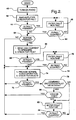
- the method of detecting and indicating speaker faults is illustrated by the flow charts of Figures 2 and 3 wherein the functional description of each block in the charts is accompanied by a number in angle brackets ⁇ nn> which corresponds to the reference number of the block.
- the method involves manual inputs, operation by the amplifier 12 and the fault circuits 16, and operations performed by the microprocessor 22.
- a DC bias is applied to each channel of the amplifier and the fault circuits 16 check for faults ⁇ 42>.
- no audio signal is applied and faults due to open load, shorts to ground or shorts to power will be revealed.
- a fault circuit changes the state of line 20 and a fault routine is entered ⁇ 46>.
- the fault routine ⁇ 46> is detailed in Figure 3 .
- the microprocessor responds to the state of line 20 by setting a fault flag and indicating a fault ⁇ 48 > by sending a message to the radio display and storing the fault flag for future examination by the diagnostic tool 26. If the radio is turned off while the fault routine is being executed ⁇ 50 > the fault detection will end ⁇ 52 >. If the radio remains on, a limited audio performance may be allowed ⁇ 54 > but it is preferred to keep the sound off during this initial fault test; however for later tests the limited audio (low volume) is permitted. Next another fault check is made ⁇ 56> so that if the fault remains ⁇ 58> the fault routine continues until the radio is turned off. Whenever the fault is cleared either due to a repair or due to an intermittent condition, the fault flag is reset, the fault indication is removed, and a fault occurred flag and fault information will be stored ⁇ 60>.
- the fault circuits 16 of the amplifier are able to identify for each channel the specific type of fault; however there is no convenient way to extract that information for diagnostic purposes.
- the amplifier may be modified to include communication capability to output the detailed fault information.
- a modified amplifier 12' includes a data storage register 90, and a clock bus 92 and a data bus 94 connect the register to the microprocessor 22.
- the fault circuits 16 for the several amplifiers channels each have four outputs for coupling specific fault data to preassigned bits D0 to D15 of the register 90.
- the fault outputs are short to B+ (power), short to ground, shorted load and open load.
- the register data is clocked onto the data bus and read by the microprocessor to determine specific fault information and to provide appropriate indication. This data is independent of the distortion signal, although this communication capability can include distortion data if desired.
- the method of Figures 2 and 3 remains the same except that the high current used in step ⁇ 66> does not have to be limited to a non-distorting level, and the steps ⁇ 78> and ⁇ 80> are omitted. Since more specific fault information is available, specific diagnosis may be accomplished by the diagnostic tool 26 as it accesses the information. Depending on the extent of the radio display 28, specific information may be shown there as well.
- the detection of speaker faults simplifies the diagnosis of radio problems and if there is a speaker fault, avoids the time and expense of unnecessary removal and testing of radios, which is usually the first step in analyzing such problems.
- the modified amplifier when used, the problem is narrowed to a particular fault in a specific channel, thereby greatly facilitating repair.
- customer satisfaction is improved by detecting and repairing speaker faults in new vehicles at the factory or at the dealership before delivery to the customer.
Landscapes
- Health & Medical Sciences (AREA)
- General Health & Medical Sciences (AREA)
- Otolaryngology (AREA)
- Physics & Mathematics (AREA)
- Engineering & Computer Science (AREA)
- Acoustics & Sound (AREA)
- Signal Processing (AREA)
- Amplifiers (AREA)
- Monitoring And Testing Of Transmission In General (AREA)
- Fittings On The Vehicle Exterior For Carrying Loads, And Devices For Holding Or Mounting Articles (AREA)
Description
- This invention relates to the indication of speaker faults to a vehicle operator or to service personnel.
- In an automotive radio system, when a speaker fault occurs the radio or perhaps one channel shuts down, quits working, or is damaged. To prevent damage, many radios use audio amplifiers with built in protection which senses a speaker fault and shuts down at least the channel serving that speaker. Other radios lack that feature. In any event, the operator or service technician will not know the cause of the failure and will assume the problem is in the radio/amplifier, and replace that. Then the same problem will occur, and a search will be made for speaker faults or other system problems. It is desirable, then, that a speaker fault should be readily recognizable so that the service can be properly directed to correcting the problem.
-
US 5631566 discloses a radio speaker short circuit detection system.US 5453716 discloses a clip detection system for limiting an audio output signal to avoid clipping.EP 0607693 discloses a method of using clipping detection to diagnose speaker faults. - It is therefore an object of the invention to overcome the above-mentioned problem. According to the present invention there is provided a vehicle radio as claimed in
claim 1 and a method of indicating speaker faults as claimed in claim 9. In one embodiment an audio amplifier with the capability to detect a speaker fault is configured to produce a signal when a fault occurs. A microprocessor responsive to such a fault signal sends a suitable message to the radio display to apprise the operator of the condition. Alternatively, the fault information is stored in memory associated with the microprocessor and is retrieved via a data bus by a diagnostic tool used by a service technician. - Fault detection begins when a radio is turned on. Then before an audio signal is applied, the amplifier is biased and a fault check is performed by the amplifier. At this stage, the fault detection feature can respond to a short to power or to ground and to an open load. If a fault is found the microprocessor executes a fault routine which effects an indication and/or stores fault data and limits the output of the radio from playing until the fault is repaired or otherwise cleared. If there is no fault or if a fault has been cleared, the operator may test for a shorted load by pressing designated radio buttons which cause a high current audio signal to be sent to the speakers. If a fault is detected then, the fault routine is entered but this time the radio is permitted to play at a reduced volume as long as the fault is present. Finally, if no fault is present, normal audio operation is provided and fault detection continues.
- The present invention will now be described, by way of example, with reference to the accompanying drawings, in which:-
-
Figure 1 is a block diagram of radio hardware including an audio amplifier for speaker fault detection according to one embodiment the invention; -
Figures 2 and3 are flow charts illustrating the method of the invention; and -
Figure 4 is a block diagram of an audio amplifier for speaker fault detection according to another embodiment of the invention. - The ensuing description refers to an automotive radio. That term is used herein to include an audio source which may be, for example, a cassette player or other source as well as a tuner.
- Referring to
Figure 1 , a radio includes anaudio source 10 providing a signal to anaudio amplifier 12 which, in this example, has four output channels, each supplying at least onespeaker 14. The amplifier is of the type which has built-incircuits 16 for detecting speaker faults in each channel and includes means for disabling any channel exhibiting a fault. Theamplifier 12 also includes adistortion detection circuit 18 which is coupled to anoutput line 20 to impose a signal on the line when distortion is present. As thus far described, the amplifier is well known for use in automotive radios where the speaker fault and protection capability is desired. It is available from SGS Thomson Microelectronics, of Milan, Italy, as a bridge audio amplifier part no. QBA TDA7385. Similar devices serving only one or two channels are also available from the same source. Here it is proposed to configure the device to couple fault signals from thefault detection circuits 16 to theline 20, so that by monitoring the line when distortion is not likely to occur the state of the line will indicate the presence of a fault. - A
microprocessor 22 is coupled to theline 20 to monitor its state and to discriminate between distortion and speaker fault signals. The microprocessor is connected to aserial data bus 24 to supply a fault signal or stored fault data to a normal dealershipdiagnostic tool 26 which is not part of the radio but is an instrument to be applied by a service technician. The radio has adisplay 28 which is coupled to themicroprocessor 22 to display a speaker fault message as well as station identification and other information. Depending on the display capability, the fault message may be, for example, "SPKR PRB", or an error code such as "ERR3".Buttons 30 or other normal radio controls provide inputs to themicroprocessor 22. - The method of detecting and indicating speaker faults is illustrated by the flow charts of
Figures 2 and3 wherein the functional description of each block in the charts is accompanied by a number in angle brackets <nn> which corresponds to the reference number of the block. The method involves manual inputs, operation by theamplifier 12 and thefault circuits 16, and operations performed by themicroprocessor 22. Each time the radio is first turned on <40> a DC bias is applied to each channel of the amplifier and thefault circuits 16 check for faults <42>. At this time no audio signal is applied and faults due to open load, shorts to ground or shorts to power will be revealed. If a fault is present <44>, a fault circuit changes the state ofline 20 and a fault routine is entered <46>. The fault routine <46> is detailed inFigure 3 . The microprocessor responds to the state ofline 20 by setting a fault flag and indicating a fault < 48 > by sending a message to the radio display and storing the fault flag for future examination by thediagnostic tool 26. If the radio is turned off while the fault routine is being executed < 50 > the fault detection will end < 52 >. If the radio remains on, a limited audio performance may be allowed < 54 > but it is preferred to keep the sound off during this initial fault test; however for later tests the limited audio (low volume) is permitted. Next another fault check is made <56> so that if the fault remains <58> the fault routine continues until the radio is turned off. Whenever the fault is cleared either due to a repair or due to an intermittent condition, the fault flag is reset, the fault indication is removed, and a fault occurred flag and fault information will be stored <60>. - Then when the fault is cleared < 62 > (returning to
Figure 2 ) the operator has the option of testing for internal speaker shorts. This test requires operator action and results in a loud unpleasant sound and will not be performed except when the operator or technician suspects there is a speaker fault. The operator action is, for example, the pressing of two buttons simultaneously, say the #1 and #4 preset buttons. If the buttons are pressed < 64 > an audio signal is sent to the speakers and a fault check is performed <66>. The signal has high current but is insufficient to cause distortion. This fault check is able to detect a shorted load. If a fault is present <68> the fault routine is entered <70>. This is the same routine (Figure 3 ) used above and this time low volume audio performance is permitted. If the fault is cleared <72> or if the button had not been pressed <64> normal audio operation is provided and fault checking continues < 74 >. If a fault is present <76> it is determined whether the fault detection and distortion detection share thesame line 20 as inFigure 1 < 78 >. This is done because the same method can be used with other amplifier arrangements. A flag could be set to identify a combined detection arrangement when the software is installed, and the flag is read to answer the inquiry <78>. If the combined detection configuration is used, and the volume setting is high <80>, it is assumed that the fault signal is the result of distortion and normal operation continues. If the volume setting is not high <80> the fault routine is entered <82>. This is the same routine (Figure 3 ) used above and this time low volume audio performance is permitted. During the fault routine limited audio performance is allowed and if the fault is cleared <84> the normal operation is restored. - The
fault circuits 16 of the amplifier are able to identify for each channel the specific type of fault; however there is no convenient way to extract that information for diagnostic purposes. The amplifier may be modified to include communication capability to output the detailed fault information. As shown inFigure 4 , a modified amplifier 12' includes adata storage register 90, and aclock bus 92 and adata bus 94 connect the register to themicroprocessor 22. Thefault circuits 16 for the several amplifiers channels each have four outputs for coupling specific fault data to preassigned bits D0 to D15 of theregister 90. The fault outputs are short to B+ (power), short to ground, shorted load and open load. Whenever a fault check is made, the register data is clocked onto the data bus and read by the microprocessor to determine specific fault information and to provide appropriate indication. This data is independent of the distortion signal, although this communication capability can include distortion data if desired. - In operation of the system as modified by the
Figure 4 communication capability, the method ofFigures 2 and3 remains the same except that the high current used in step <66> does not have to be limited to a non-distorting level, and the steps <78> and <80> are omitted. Since more specific fault information is available, specific diagnosis may be accomplished by thediagnostic tool 26 as it accesses the information. Depending on the extent of theradio display 28, specific information may be shown there as well. - It will thus be seen that the detection of speaker faults according to the invention simplifies the diagnosis of radio problems and if there is a speaker fault, avoids the time and expense of unnecessary removal and testing of radios, which is usually the first step in analyzing such problems. Moreover, when the modified amplifier is used, the problem is narrowed to a particular fault in a specific channel, thereby greatly facilitating repair. In addition customer satisfaction is improved by detecting and repairing speaker faults in new vehicles at the factory or at the dealership before delivery to the customer.
Claims (12)
- In a vehicle radio having a plurality of speakers (14) and amplifier means (12) for driving the plurality of speakers (14) and manually operated means including means for setting the volume of the speakers (14), an apparatus for indicating speaker faults comprising:fault detection means (16) associated with the amplifier means (12) for detecting speaker faults and for issuing a fault signal when a fault is detected;distortion detection means (18) associated with the amplifier means (12) for detecting speaker distortion and for issuing a distortion signal when distorted is detected;means for determining if the volume setting of the speakers is high; characterized bya microprocessor (22) connected to the fault detection means (16), the distortion detection means (18) and the speaker volume determining means and programmed to set fault flag and indicate a fault:-a) when a fault signal is issued by either the fault detection means or the distortion detection means; andb) when the speaker volume setting is not high; andmeans (28) for communicating a fault indication to service personnel, wherein the microprocessor (22) is further programmed, when the radio is just turned on and the amplifier means (12) is biased, and then, repeatedly, during normal radio operation, to check for a fault signal after a fault has been detected, and to determine whether the fault is still present and to reset the fault flag and save any fault information and provide normal audio operation if the fault is not present.
- An apparatus as claimed in claim 1, wherein the fault detected by the fault detection means comprises open circuits, shorts to ground or shorts to power.
- An apparatus as claimed in claim 1 or claim 2, wherein the microprocessor (22) is further programmed to limit the output of the radio from playing until the indicated fault is repaired or otherwise cleared.
- An apparatus as claimed in any preceding claim, further comprising manually operable means for triggering a high current audio signal to the speakers (14) to test the speakers (14).
- An apparatus as claimed in claim 4, wherein the high current audio signal is insufficient to cause dynamic distortion.
- An apparatus as claimed in any preceding claim, wherein the fault communication means comprises a radio display (28) for displaying a speaker fault message.
- An apparatus as claimed in any of claims 1 to 5, wherein the fault communication means comprises a data bus (94) for communicating with service instrumentation; and
the microprocessor (22) is connected to the data bus (94), whereby the fault indication is supplied over the data bus (94) to the instrumentation. - An apparatus as claimed in any preceding claim, wherein the means (16) for detecting speaker faults includes means for determining the specific type of fault and which of several channels contains the fault.
- A method of indicating speakers faults in a vehicle radio having a plurality of speakers (14) and amplifier means (12) for driving the plurality of speakers (14, said method comprising the steps of:-a) when the radio is just turned on and the amplifier is biased and then, repeatedly, during normal radio operation;b) checking for a fault in each of the speakers (14);c) checking for distortion in each of the speakers (14);d) if:-i) a fault is present; orii) if distortion is detected and a volume setting is not high setting a fault flag and indicating a fault;
the method further comprising the step of, when the radio is just turned on, applying a bias to the plurality of speakers (14) without applying any audio signal and determining whether one or more of the speakers (14) has an open load, short to ground or short to power, and, if so, setting the fault flag and indicating a fault; characterised in that following steps (b),(c) and (d), the method includes the further step of resetting the fault flag, saving any fault information and providing normal audio performance if no fault is present. - A method as claimed in claim 9 including the further step of limiting the output of the radio from playing when the fault flag is set and a fault is indicated.
- A method as claimed in claim 9 or claim 10, including the further step of manually triggering a high current audio signal and performing steps (b), (c) and (d).
- A method as claimed in claim 11, wherein said high current audio signal is insufficient to cause dynamic distortion.
Applications Claiming Priority (2)
| Application Number | Priority Date | Filing Date | Title |
|---|---|---|---|
| US08/943,214 US5940518A (en) | 1997-10-06 | 1997-10-06 | Method and apparatus for indicating speaker faults |
| US943214 | 1997-10-06 |
Publications (3)
| Publication Number | Publication Date |
|---|---|
| EP0909114A2 EP0909114A2 (en) | 1999-04-14 |
| EP0909114A3 EP0909114A3 (en) | 2005-06-22 |
| EP0909114B1 true EP0909114B1 (en) | 2008-11-12 |
Family
ID=25479257
Family Applications (1)
| Application Number | Title | Priority Date | Filing Date |
|---|---|---|---|
| EP98203060A Expired - Lifetime EP0909114B1 (en) | 1997-10-06 | 1998-09-14 | Method and apparatus for indicating speaker faults |
Country Status (3)
| Country | Link |
|---|---|
| US (1) | US5940518A (en) |
| EP (1) | EP0909114B1 (en) |
| DE (1) | DE69840205D1 (en) |
Families Citing this family (26)
| Publication number | Priority date | Publication date | Assignee | Title |
|---|---|---|---|---|
| JP3908434B2 (en) * | 2000-03-06 | 2007-04-25 | パイオニア株式会社 | Information equipment with speakers |
| WO2002001391A2 (en) * | 2000-06-23 | 2002-01-03 | Ecomsystems, Inc. | System and method for computer-created advertisements |
| US6950525B2 (en) * | 2001-10-12 | 2005-09-27 | General Motors Corporation | Automated system and method for automotive time-based audio verification |
| US7215784B1 (en) * | 2001-12-13 | 2007-05-08 | Delphi Technologies, Inc. | Programmable audio system for automotive vehicles |
| US8005230B2 (en) * | 2002-12-20 | 2011-08-23 | The AVC Group, LLC | Method and system for digitally controlling a multi-channel audio amplifier |
| US7239005B2 (en) * | 2003-07-18 | 2007-07-03 | Yamaha Corporation | Semiconductor device with bypass capacitor |
| US20050036631A1 (en) * | 2003-08-11 | 2005-02-17 | Honda Giken Kogyo Kabushiki Kaisha | System and method for testing motor vehicle loudspeakers |
| US8468444B2 (en) * | 2004-03-17 | 2013-06-18 | Targit A/S | Hyper related OLAP |
| US20050249353A1 (en) * | 2004-05-05 | 2005-11-10 | Visteon Global Technologies, Inc. | System and method for detecting fault conditions on audio output channels |
| US7774295B2 (en) * | 2004-11-17 | 2010-08-10 | Targit A/S | Database track history |
| ATE511098T1 (en) | 2005-12-06 | 2011-06-15 | Harman Int Ind | DIAGNOSTIC SYSTEM FOR A POWER CONVERTER |
| EP2021953A2 (en) * | 2006-05-16 | 2009-02-11 | Targit A/S | A method of preparing an intelligent dashboard for data monitoring |
| DK176532B1 (en) | 2006-07-17 | 2008-07-14 | Targit As | Procedure for integrating documents with OLAP using search, computer-readable medium and computer |
| US9237685B2 (en) | 2006-08-18 | 2016-01-12 | Delphi Technologies, Inc. | Lightweight audio system for automotive applications and method |
| US8264856B2 (en) | 2006-08-18 | 2012-09-11 | Delphi Technologies, Inc. | Lightweight audio system for automotive: applications and method |
| US7733659B2 (en) * | 2006-08-18 | 2010-06-08 | Delphi Technologies, Inc. | Lightweight audio system for automotive applications and method |
| DK176516B1 (en) * | 2007-04-30 | 2008-06-30 | Targit As | Computer-implemented method and computer system and computer readable medium for low video, pod-cast or slide presentation from Business-Intelligence-application |
| CN101785182A (en) * | 2007-08-16 | 2010-07-21 | 汤姆逊许可公司 | network audio processor |
| US9118985B2 (en) * | 2012-12-04 | 2015-08-25 | Bose Corporation | Communication of diagnostic information from satellite to host |
| JP2014183543A (en) * | 2013-03-21 | 2014-09-29 | Toshiba Corp | Acoustic output device |
| DE102013222943A1 (en) * | 2013-11-12 | 2015-05-13 | Robert Bosch Gmbh | Display device for a motor vehicle and test method for a display device of a motor vehicle |
| CN104796840B (en) * | 2015-04-01 | 2018-07-17 | 南京新索奇科技有限公司 | A kind of sound pick up equipment and self checking method with self-checking function |
| US10778160B2 (en) | 2016-01-29 | 2020-09-15 | Dolby Laboratories Licensing Corporation | Class-D dynamic closed loop feedback amplifier |
| WO2017132583A2 (en) * | 2016-01-29 | 2017-08-03 | Dolby Laboratories Licensing Corporation | Multi-channel cinema amplifier with power-sharing, messaging and multi-phase power supply |
| FR3087076B1 (en) * | 2018-10-08 | 2022-02-25 | Arkamys | METHOD AND DEVICE FOR CONTROLLING THE DISTORTION OF A SPEAKER SYSTEM EMBEDDED IN A VEHICLE |
| CN111050265B (en) * | 2019-11-27 | 2021-09-14 | 深圳易科声光科技股份有限公司 | Automatic audio link detection method and device |
Family Cites Families (4)
| Publication number | Priority date | Publication date | Assignee | Title |
|---|---|---|---|---|
| US5450624A (en) * | 1993-01-07 | 1995-09-12 | Ford Motor Company | Method and apparatus for diagnosing amp to speaker connections |
| US5361305A (en) * | 1993-11-12 | 1994-11-01 | Delco Electronics Corporation | Automated system and method for automotive audio test |
| JPH07234260A (en) * | 1993-11-22 | 1995-09-05 | Chrysler Corp | Wireless device speaker short-circuit detection system and short-circuit failure indication method |
| US5453716A (en) * | 1993-11-22 | 1995-09-26 | Chrysler Corporation | Adjustable clip detection system |
-
1997
- 1997-10-06 US US08/943,214 patent/US5940518A/en not_active Expired - Lifetime
-
1998
- 1998-09-14 DE DE69840205T patent/DE69840205D1/en not_active Expired - Lifetime
- 1998-09-14 EP EP98203060A patent/EP0909114B1/en not_active Expired - Lifetime
Also Published As
| Publication number | Publication date |
|---|---|
| EP0909114A2 (en) | 1999-04-14 |
| DE69840205D1 (en) | 2008-12-24 |
| US5940518A (en) | 1999-08-17 |
| EP0909114A3 (en) | 2005-06-22 |
Similar Documents
| Publication | Publication Date | Title |
|---|---|---|
| US5940518A (en) | Method and apparatus for indicating speaker faults | |
| EP0607693B1 (en) | Method and apparatus for diagnosing AMP to Speaker Connections | |
| JP3715208B2 (en) | Railway remote radio testing system and method | |
| JPH0133980B2 (en) | ||
| US8090112B2 (en) | Self-diagnostic system for monitoring electrical equipment | |
| US9041412B2 (en) | Methods of testing a connection between speakers and a power amplifier and devices therefor | |
| CN110262921A (en) | A fault diagnosis method, system and device for a vehicle's on-board speaker | |
| CN112291697B (en) | A speaker open circuit detection circuit | |
| US5631566A (en) | Radio speaker short circuit detection system | |
| JPH08289399A (en) | Circuit device for testing connection of audio reproducing device to audio signal source | |
| JP2973250B2 (en) | Failure diagnosis method | |
| US9781527B2 (en) | Smart plug and play automatic OBD-II system tester | |
| JPH10153634A (en) | Speaker output self-diagnosis device | |
| JP3473803B2 (en) | Speaker inspection equipment | |
| US6560465B1 (en) | Method and apparatus for controlling and maintaining a tower top low noise amplifier | |
| CN117268781A (en) | Vehicle data marking method and device, nonvolatile storage medium and vehicle | |
| KR100587794B1 (en) | Fault diagnosis device of car antenna | |
| KR100238728B1 (en) | Self-diagnosis apparatus and method of cell phone | |
| US7092836B2 (en) | Method for locating wiring swap in a hi-fix structure of a simultaneous multi-electronic device test system | |
| KR100239320B1 (en) | Normal operation detection method of voice recognition device for automobile | |
| CN109856482A (en) | A kind of method of quick test USB-PD module | |
| KR20000000539A (en) | Display device having self diagnosis function and control method thereof | |
| KR100306759B1 (en) | Microphone Orientation Test Device for Multimedia Monitor | |
| KR19980048193A (en) | Audio bad diagnosis device | |
| JP2000113567A (en) | Sound equipment |
Legal Events
| Date | Code | Title | Description |
|---|---|---|---|
| PUAI | Public reference made under article 153(3) epc to a published international application that has entered the european phase |
Free format text: ORIGINAL CODE: 0009012 |
|
| AK | Designated contracting states |
Kind code of ref document: A2 Designated state(s): AT BE CH CY DE DK ES FI FR GB GR IE IT LI LU MC NL PT SE |
|
| AX | Request for extension of the european patent |
Free format text: AL;LT;LV;MK;RO;SI |
|
| RAP1 | Party data changed (applicant data changed or rights of an application transferred) |
Owner name: DELPHI TECHNOLOGIES, INC. |
|
| PUAL | Search report despatched |
Free format text: ORIGINAL CODE: 0009013 |
|
| AK | Designated contracting states |
Kind code of ref document: A3 Designated state(s): AT BE CH CY DE DK ES FI FR GB GR IE IT LI LU MC NL PT SE |
|
| AX | Request for extension of the european patent |
Extension state: AL LT LV MK RO SI |
|
| 17P | Request for examination filed |
Effective date: 20051222 |
|
| AKX | Designation fees paid |
Designated state(s): DE FR GB IT |
|
| 17Q | First examination report despatched |
Effective date: 20060321 |
|
| 17Q | First examination report despatched |
Effective date: 20060321 |
|
| GRAP | Despatch of communication of intention to grant a patent |
Free format text: ORIGINAL CODE: EPIDOSNIGR1 |
|
| GRAS | Grant fee paid |
Free format text: ORIGINAL CODE: EPIDOSNIGR3 |
|
| GRAA | (expected) grant |
Free format text: ORIGINAL CODE: 0009210 |
|
| AK | Designated contracting states |
Kind code of ref document: B1 Designated state(s): DE FR GB IT |
|
| REG | Reference to a national code |
Ref country code: GB Ref legal event code: FG4D |
|
| REF | Corresponds to: |
Ref document number: 69840205 Country of ref document: DE Date of ref document: 20081224 Kind code of ref document: P |
|
| PLBE | No opposition filed within time limit |
Free format text: ORIGINAL CODE: 0009261 |
|
| STAA | Information on the status of an ep patent application or granted ep patent |
Free format text: STATUS: NO OPPOSITION FILED WITHIN TIME LIMIT |
|
| 26N | No opposition filed |
Effective date: 20090813 |
|
| PG25 | Lapsed in a contracting state [announced via postgrant information from national office to epo] |
Ref country code: IT Free format text: LAPSE BECAUSE OF FAILURE TO SUBMIT A TRANSLATION OF THE DESCRIPTION OR TO PAY THE FEE WITHIN THE PRESCRIBED TIME-LIMIT Effective date: 20081112 |
|
| REG | Reference to a national code |
Ref country code: FR Ref legal event code: PLFP Year of fee payment: 18 |
|
| REG | Reference to a national code |
Ref country code: FR Ref legal event code: PLFP Year of fee payment: 19 |
|
| REG | Reference to a national code |
Ref country code: FR Ref legal event code: PLFP Year of fee payment: 20 |
|
| PGFP | Annual fee paid to national office [announced via postgrant information from national office to epo] |
Ref country code: FR Payment date: 20170925 Year of fee payment: 20 Ref country code: GB Payment date: 20170927 Year of fee payment: 20 |
|
| PGFP | Annual fee paid to national office [announced via postgrant information from national office to epo] |
Ref country code: DE Payment date: 20170927 Year of fee payment: 20 |
|
| REG | Reference to a national code |
Ref country code: DE Ref legal event code: R071 Ref document number: 69840205 Country of ref document: DE |
|
| REG | Reference to a national code |
Ref country code: GB Ref legal event code: PE20 Expiry date: 20180913 |
|
| PG25 | Lapsed in a contracting state [announced via postgrant information from national office to epo] |
Ref country code: GB Free format text: LAPSE BECAUSE OF EXPIRATION OF PROTECTION Effective date: 20180913 |