BACKGROUND OF THE INVENTION
-
The present invention relates to satellite
communication systems. More particularly, the present
invention relates to a system and method that allows a
satellite to process multiple spread-spectrum uplink
channels, for example, Code Division Multiple Access (CDMA)
channels, without substantially increasing the required
satellite hardware.
-
CDMA is a technique used to communicate large amounts
of information contained in many user signals
simultaneously and at low power levels using a large
bandwidth. CDMA is generally considered a "spread-spectrum"
technology. In operation, CDMA spreads the information
contained in a particular user signal over a much greater
bandwidth than the original user signal. Starting from a
rate of approximately 9.6 Kilobits per second (9.6 Kbps),
for example, CDMA may spread user signals to a transmitted
rate of approximately 1.23 Megabits per second. In
accomplishing spreading, CDMA applies orthogonal codes to
the data bits associated with user signals. The resulting
coded data bits may then be transmitted along with the user
signals of all the other users without appreciable
interference by merging the coded data bits with a pseudo-random
noise (PN) sequence. When the composite signal is
received, the orthogonal code applied to a particular user
signal is removed in a process called "despreading" that
separates the user signal out from the composite signal and
returns the user signal to its original rate.
-
The military is a traditional user of spread spectrum
technology. Because the user signal is spread out along a
wide bandwidth, it is very difficult to jam, difficult to
interfere with, and difficult to even discover that the
user signal is in the air. Due to the low transmission
power levels and spreading effect of the digital codes, the
composite signal appears as nothing more than a slight rise
in the existing "noise floor" . Other technologies, for
example, Time Division Multiple Access (TDMA) tend to
concentrate large amounts of information and power in a
small portion of bandwidth, thus making the transmission
much easier to detect and interfere with.
-
CDMA technology is also applied in the digital mobile
telephone market and offers numerous advantages for its
users. Among these advantages are that the apparent
capacity of a CDMA system may be 8 to 10 times larger than
that of traditional analog cellular systems, such as
Advanced Mobile Phone Service (AMPS) and 4 to 5 larger than
that of a digital cellular system such as the Global System
for Mobile communications (GSM) system. A CDMA system may
also enjoy improved call quality and enhanced privacy as
well as provide longer battery life for portable phones.
-
CDMA is poised to take a major role in future
communications systems. After first entering commercial
service in Hong Kong in 1995, CDMA is now in commercial
service in, for example, the United States, Korea, Canada,
India, and China.
-
Along with the need to communicate large amounts of
information is the need to communicate that information via
satellite. Satellites provide wide ranging coverage of
large parts of the planet and can easily send signals where
it is impossible or uneconomical to place physical
conductors like copper wire or fiber optic cable.
-
Today, however, satellite uplinks, may consist of
hundreds of simultaneous users, particularly if the uplinks
carry CDMA transmissions. A single satellite may have, for
example, 30 or 40 uplink transponders (essentially receive
antennas), each able to accept an uplink beam with a
bandwidth of 250 MHz. The resultant total uplink data path
would then have a capacity of nearly 8 to 10 gigabits per
second.
-
CDMA is capable of generating massive amounts of data
for an uplink beam to carry. Transmission systems may, for
example, divide the 250 MHz uplink beam bandwidth into
lower bandwidth uplink channels (twenty 12.5 MHz uplink
channels, for example). Each uplink channel may then use
CDMA techniques to carry data channels for hundreds of
users. In order for a conventional satellite to despread
and decode the data channel for each user, the satellite
would have to carry hundreds (perhaps thousands) of sets of
heavy, complex decoding electronics, and generate enormous
amounts of power. Additional circuitry, of course, leads
to a corresponding increase in required power and satellite
size.
-
Increasing the size, weight, and onboard power of a
satellite so that it can decode more data channels drives
up the cost of the satellite dramatically. Not only does
the satellite itself become more expensive because of the
additional circuitry and solar panels used to provide
onboard power, but it also costs more to launch the
satellite because larger rockets and more propellant are
required to put the satellite into orbit. Satellite size,
weight, and power restrictions thereby prohibit the
satellite from handling the large numbers of data channels
that modern communications techniques can generate.
-
Thus a need is present in the industry for an improved
communications system, which overcomes the disadvantages
discussed above and previously experienced.
BRIEF SUMMARY OF THE INVENTION
-
It is therefore an object of the present invention to
allow a single satellite to process numerous CDMA uplink
channels efficiently.
-
It is therefore an object of the present invention to
enable a satellite to process CDMA uplink channels without
a significant increase in the size of the satellite.
-
It is an object of the present invention to enable a
satellite to process CDMA uplink channels without a
significant increase in weight of the satellite.
-
It is another object of the present invention to
enable a satellite to process uplink channels without a
significant increase in power required by the satellite.
-
It is a further object of the present invention to
increase the total number of data channels a single
satellite may process.
-
The present invention includes a user terminal that is
responsible for transmitting user signals to a satellite.
Before transmitting, the user terminal monitors a downlink
beam broadcast by the satellite to acquire initial timing
information (a symbol clock), a synchronization word that
appears at regular intervals in the downlink beam, and a
timing correction value. The user terminal generates an
initial system clock based on the symbol clock, then
transmits a timing correlation code to the satellite. The
transmission of the timing correlation code is offset from
the timing of the synchronization word by the timing
correction value.
-
The satellite receives the timing correlation code,
compares its arrival to the satellite internal symbol
clock, and generates revised timing correction information.
The timing correction information represents an adjustment
to the amount of time the terminal waits from the
synchronization word before transmitting. The satellite
sends the timing correction information to the user
terminal, which receives the timing correction information
and adjusts its time delay accordingly to achieve
synchronization.
-
Once in synchronization, the user terminal
reinitializes its timing and code word generators and
begins to process user signals. Each user signal may be
spread and combined with many additional user signals in a
CDMA fashion for transmission to the satellite in a single
uplink channel, for example.
-
In the satellite, the received CDMA uplink channel is
processed by hardware that separates out individual uplink
channels and then despreads the user signals contained
within the uplink channels. The despreading hardware may
incorporate a Fast Hadamard Transform (FHT) and would be
used, for example, in conjunction with Walsh-Hadamard
spreading codes in the user terminal. In the case where
multiple uplink channels are present in a single uplink
beam, the satellite may use an FFT processor to separate
out the individual uplink channels. Each individual output
of the FFT processor may be connected an FHT despreader.
The outputs of the FHT despreader are individual user
signals, which may then be processed in any desired manner,
including conventional demodulation, switching, or
multiplexing.
BRIEF DESCRIPTION OF THE SEVERAL VIEWS OF THE DRAWINGS
-
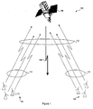
- Figure 1 shows a communications system including user
terminals and a satellite.
- Figure 2 shows a block diagram of a user terminal
including timing, synchronization, and signal spreading
blocks.
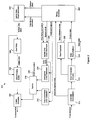
- Figure 3 shows a block diagram of a satellite,
including uplink channel processing and time reference
generators.
- Figure 4a shows a first set of timing relationships
between two user signals in which the signals are slightly
out of alignment.
- Figure 4b shows a set of timing relationships between
two user signals in which the signals are in alignment.
- Figure 4c shows a second set of timing relationships
between two user signals in which the code words are not in
alignment.
-
DETAILED DESCRIPTION OF THE INVENTION
-
Turning now to Figure 1, that figure shows a diagram
of a communications system 100 including a first group of
user terminals 102 and a second group of user terminals 104
in communication with a satellite 106. Both groups of user
terminals 102 and 104 communicate with the satellite 106 by
transmitting in the bandwidth assigned to a single uplink
beam (for example, a 250 MHz bandwidth assigned to a
predetermined satellite transponder). As noted above, the
uplink beam bandwidth may be divided into numerous lower
bandwidth uplink channels. In Figure 1, the group of user
terminals 102 communicates in the frequency range allocated
to a first uplink channel 114 in the uplink beam, while the
group of user terminals 104 communicates in the frequency
range allocated to a second uplink channel 116 in the same
uplink beam. In Figure 1, the uplink channels 114 and 116
form the uplink beam 112.
-
In addition, each of the uplink channels may support
the simultaneous transmission of data channels provided by
numerous users through the use of spread spectrum
transmission techniques, for example CDMA. The number of
users supported by a single uplink channel depends in part
on the number of orthogonal codes available to the groups
of user terminals 102 and 104. Although Figure 1 shows
groups of user terminals 102 and 104 containing three user
terminals, in practice many more user terminals may be
added to those transmitting on the same uplink channel. As
will be explained in more detail below, each additional
user terminal applies an orthogonal code to its
transmission to prevent interference with other
transmissions in the same uplink channel. Thus the
structure of Figure 1 includes user terminals generating
data channels which are grouped into uplink channels in an
uplink beam.
-
The satellite 106 communicates, in part, with the
groups of user terminals 102 and 104 through the downlink
beam 108. In general, all user terminals transmitting in
the same uplink beam receive the downlink beam 108. The
downlink beam 108 includes regular data transmissions
destined fob the various user terminals as well as special
timing control information.
-
In a preferred embodiment, the groups of user
terminals 102 and 104 extract two pieces of timing control
information from the downlink beam 108. The first piece of
timing control information is a symbol clock reference.
The symbol clock reference is an inherent part of the
structure of the downlink beam 108 which is produced as a
natural consequence of the satellite 106 transmitting data
to the ground.
-
The groups of user terminals 102 and 104 recover the
symbol clock in the downlink beam 108 during the process of
downlink demodulation and bit synchronization. In general,
user terminals using the same uplink beam will synchronize
their internal symbol clocks to the symbol clock reference
provided for that uplink beam in the downlink beam 108.
-
The second piece of timing control information
provided in the downlink beam 108 is a regularly
transmitted synchronization word. The role of the
synchronization word will be discussed below.
-
Turning now to Figure 2, it shows a block diagram
representative of an individual terminal 110 in the groups
of user terminals 102 and 104. The individual terminal 110
includes a downlink demodulator 210, error correction
circuitry 214, a data demultiplexor 218, a time flywheel
222, and a timing controller 226. Also included in the
individual terminal 110 are an uplink chip clock generator
230, an uplink data clock generator 234, an orthogonal code
generator 238, a time correlation code generator 242, a
switch 246 with a code word select line 248, a data phasing
buffer 250, and a CDMA spreader 254. User data 258 also
flows through the individual terminal 110 and will be
communicated to the satellite 106 in an uplink channel in
the first uplink beam.
-
Turning next to Figure 3, a block diagram of the
satellite 106 is illustrated. The satellite 106 includes
an analog to digital (A/D) converter 310, a data input
buffer 314, a Fast Fourier Transform (FFT) pre-sum stage
318, a wideband FFT processor 322, and a Fast Hadamard
Transform (FHT) despreader 326. The satellite 106 also
includes a calibration demodulator 330, a control processor
334, a downlink data formatter 338, and a time reference
generator 342.
-
In operation, the individual terminal 110 begins by
synchronizing with the reference timing running in the
satellite 106. Returning to Figure 2, the individual
terminal 110 begins the synchronization process by
monitoring the downlink beam 108 for timing control
information. The individual terminal 110 uses the downlink
demodulator 210 to remove the modulation from the downlink
data carried by the downlink beam 108. The downlink
demodulator 210 also contains the circuitry necessary to
establish bit synchronization with the downlink beam 108.
The data in the downlink beam 108 may be modulated with,
for example, Quadrature Phase Shift Keying (QPSK), Binary
Phase Shift Keying (BPSK), or another efficient digital
modulation scheme.
-
As explained above, the timing control information
present in the downlink beam 108 includes a synchronization
word and an inherent symbol clock reference. In general, a
symbol may be considered to be an encoded, modulated piece
of a larger signal that represents a predetermined number
of bits of information. In QPSK, for example, each symbol
represents two bits of information.
-
The downlink demodulator 210 locks onto the symbol
clock reference and forwards it to the timing controller
226. In response, the timing controller generates a system
clock to synchronize the first user terminal with the
satellite 106. After demodulation, the downlink data is
checked for errors.
-
The error correction circuitry 214 detects and
corrects errors in the downlink data before further
processing occurs. The error correction circuitry 214 may
take advantage of any error correcting or error checking
codes applied to the downlink data before transmission.
For example, Cyclic Redundancy Check (CRC) coded downlink
data may be checked for errors, while more sophisticated
codes such as Hamming codes may detect and correct certain
errors in the downlink data. The error correction
circuitry 214 also detects the anticipated data pattern of
the synchronization word transmitted in the downlink beam
108 and sends it to the time flywheel 222. The
synchronization word is used to control the timing of the
start of transmission of code words, which are collections
of symbols. Corrected downlink data that is control
information (for example, a reset command) is sent by the
downlink data demultiplexor 218 to the timing controller
226, while corrected downlink data of other types (for
example, user data) may be sent to other processing units
(not shown) in the individual terminal 110.
-
The time flywheel 222 establishes a synchronization
word time reference for the individual terminal 110. The
synchronization word is a time marker to which the
individual terminal 110 aligns its code word transmission.
The time flywheel 222 predicts the presence of the
synchronization word in the downlink beam 108 based on an
anticipated repetition frequency and data pattern for the
synchronization word (this information may be programmed
into the individual terminal 110 before it starts
operation). The repetition period may be a multiple of the
code word length used in the individual terminal 110 (the
code word length is the total length of a predetermined
number of symbols transmitted by the individual terminal
110). As an example, the repetition rate for the
synchronization word may be equal to one every 100 code
words. Each time the synchronization word appears, the
timing controller 226 may adjust its system clock so that
the timing of code words transmission by the individual
terminal 110 is more closely matched to the satellite 106
reference clocks.
-
When the time flywheel 222 receives the same predicted
synchronization word from the error correction circuitry
214 at the anticipated interval a predetermined number of
successive times, the time flywheel 222 determines that
synchronization has, in fact, been established and forwards
a timing reference pulse to the timing controller 226. The
timing reference pulse is used to control the timing of
code word transmissions by the individual terminal 110.
The number of repetitions necessary to establish
synchronization can be varied and may, for example, be 3 or
more.
-
The timing controller 226 takes the symbol clock
reference from the downlink demodulator 210 and the timing
reference pulse from the time flywheel 222 and uses them to
generate a system clock. The system clock frequency is
generally locked to the symbol clock reference provided by
the downlink beam 108, although timing corrections may be
made by the timing controller 226 according to instructions
from the satellite 106. The symbol clock reference
provided by the satellite 106 thus establishes a common
symbol transmit rate for the uplink data in the uplink
channel used by the individual terminal 110.
-
Timing corrections may be required to align data
channel symbols and code words in the uplink channels sent
in the uplink beam 112 with the rest of the symbols and
code words sent in the other uplink channels present in the
uplink beam 112. Referring to Figure 3, these timing
corrections will allow the satellite 106 to process the
uplink channels efficiently, as will be described in more
detail below. Figure 4a shows a timing diagram
illustrating the timing parameters of interest. A first
user signal 410 is shown that consists of symbols S1, S2,
and S3 that are transmitted in a first uplink channel in
the uplink beam 112. A second user signal 414 is also
shown that consists of symbols S4, S5, and S6 that are
transmitted in a second uplink channel in uplink the beam
122.
-
Continuing with reference to Figure 4a, Symbols S1,
S2, and S3 together form a code word in the first user
signal 410, and symbols S4, S5, and S6 form a code word in
the second user signal 414. The symbols are shown in a
simplified format so that the timing relationships may be
more clearly described. In practice, the symbols may be
modulated and encoded such that they would not, of course,
appear to be square wave signals. Furthermore, the number
of symbols that constitute a code word may vary
considerably from implementation to implementation. Figure
4a also shows the symbol time for the symbols. As
described above, the first user signal 410 and the second
user signal 414 share the same symbol time, as both will be
transmitted on the same uplink beam 112.
-
Turning to Figure 2, the symbol time depends on the
system clock generated by the timing controller 226, which
in turn is generally locked to the symbol clock reference
transmitted in downlink beam 108. The system clock is used
to generate a chip clock, which directly controls the rate
at which user data 258 is encoded or spread for
transmission in an uplink channel. Because the symbols are
modulated pieces of the spread user data, the symbol clock
reference also controls the symbol time. Each piece of
encoded user data spread into the uplink channel is called
a "chip". The satellite 106 may adjust the user terminal
110 chip clock through the symbol clock reference to
provide a transmitted chip rate of, for example, 5-30
million chips per second, although other faster and slower
rates are also attainable.
-
Initially, the first user signal 410 and the second
user signal 414 may reach the satellite 106 out of
alignment with each other. This is indicated in Figure 4a
as a symbol offset. The symbol offset may be caused by a
variety of factors including initial (startup) timing
uncertainties, satellite 106 orbit eccentricities, and
unexpected satellite 106 movement. Because unexpected
changes in the uplink channel propagation to the satellite
106 may occur, the satellite 106 may allow its control
processor 334 to evaluate the alignment of the user signals
periodically, possibly as a background process. If the
control processor detects a misalignment in the user
signals above a preset threshold, it may then transmit new
timing adjustment information to some or all of the user
terminals communicating with the satellite 106. The user
terminals would then respond by adjusting their internal
clocks to bring the user signals back into alignment.
-
The satellite 106 receives the first user signal 410
and the second user signal 414 in the first uplink beam
112. The satellite 106 periodically monitors the alignment
of the signals it receives and transmits timing correction
information down to the user terminals through the downlink
beam 108. A misalignment of approximately one-quarter of a
chip may be tolerated without correction by the satellite
106. With respect to the user signals 410 and 414 shown in
Figure 4a, the satellite may communicate a timing
correction command to the sender of the second user signal
414 in order to bring the first user signal 410 and second
user signal 414 into alignment.
-
Two aligned user signals are shown in Figure 4b as a
first aligned user signal 418 and a second aligned user
signal 422. Note that the timing adjustment sent by the
satellite 106 not only has the effect of aligning the
symbols in the aligned user signals 418 and 422, but it
also aligns the code words in the aligned user signals 418
and 422 as well. When the code words are substantially
aligned, they are considered to be in the same "epoch" (and
thus two code words in the same epoch may generally be
considered to be in alignment). The ability of the
satellite 106 to align the code words is one step in
allowing the satellite 106 to efficiently process the
aligned user signals 418 and 422.
-
An example of user signals that are out of alignment
even though the individual symbols are aligned is shown in
Figure 4c. In Figure 4c, a first unaligned signal 426 and
a second unaligned signal 430 are shown offset by one
symbol. Thus, the satellite 106 receives symbols from the
unaligned signals 426 and 430 simultaneously, but does not
receive the code words in the unaligned signals 426 and 430
simultaneously. Again, the satellite 106 may correct the
misalignment by transmitting timing correction information
to the sender of either of the unaligned signals 426 or 430
to bring the signals into the alignment shown in Figure 4b.
-
The first user terminal 110 may perform an initial
time alignment using the system clock it has recovered from
the downlink beam 108. The first step in this process is
to generate a chip clock for the user terminal 110. The
uplink chip clock generator 230 shown in Figure 2 provides
a chip clock that may be used by the time correlation code
generator 242 to generate timing codes (a particular type
of orthogonal code) for initial time alignment, or by the
orthogonal code generator 238 to select orthogonal codes
for CDMA spreading. Note that the switch 246 controls
whether the output of the time correlation code generator
242 or the orthogonal code generator 238 is sent to the
CDMA spreader 254. Thus, the switch 246 acts like a
multiplexer under control of the code word select line 248.
For initial timing alignment, the code word select input
causes the switch 246 to connect the output of the time
correlation code generator 242 to the CDMA spreader 254.
-
The timing codes used by the time correlation code
generator 242 are chosen such that the satellite 106 can
more easily detect the code and calculate timing correction
information. Barker codes are generally acceptable for use
by the time correlation code generator 242 because of their
excellent auto-correlation properties. The satellite 106
receives the timing codes and computes any timing
correction necessary to bring the uplink channels in the
user terminal into alignment with other uplink channels in
the uplink beam 112. The timing correction information is
then transmitted to the first user terminal 110.
-
Once the user terminal 110 has completed its time
alignment, it may proceed to send the user data 258 to the
satellite 106. The user terminal 110 sets the code select
line of the switch 246 to select the output of the
orthogonal code generator 238. The orthogonal code
generator 238 may either contain or may be able to generate
(through fast logic, for example) orthogonal codes that can
be used to encode user data for transmission to the
satellite 106. Orthogonal codes generally suitable include
those with minimal self interference properties. Examples
of such codes include Walsh codes and Walsh-Hadamard codes.
In a preferred embodiment, the orthogonal code generator
238 uses Walsh-Hadamard codes because they also have a
corresponding Fast Hadamard Transform which the satellite
106 may use to quickly and efficiently decode the Walsh-Hadamard
encoded user data.
-
In order to transmit the user data 258, the user
terminal 110 provides the system clock generated by the
timing controller 226 to an uplink data clock generator
234. In a preferred embodiment of the invention, the
uplink data clock generator 234 produces an uplink data
clock that clocks data out of the data phasing buffer 250
in such a manner that it arrives coincident with the
orthogonal codes generated by the orthogonal code generator
238. Alternatively, the user data 258 may be timed
directly from the uplink data clock and connected directly
to the CDMA spreader 254.
-
The CDMA spreader 254 generates a wideband signal
containing the encoded user data according to CDMA coding
principles. The wideband signal is then transmitted in an
uplink channel to the satellite 106, modulation and power
amplification (not shown).
-
There is no inherent limitation on the number of CDMA
spreaders 254 that the user terminal 110 may use. A single
user terminal may, for example, contain two CDMA spreaders
254 and thereby generate two data channels, in an uplink
channel. In such a case, the output of the two CDMA
spreaders, after modulation, would be combined by the user
terminal 110 before transmission in the uplink beam 112.
The individual symbols transmitted in the two data channels
could then correspond to the aligned user signals 418 and
422 shown in Figure 4b.
-
The operation of the satellite 106 is described next
with reference to Figure 3. The satellite 106 employs an
analog to digital converter 310 to convert the analog
signals received by the satellite receive antennae (not
shown) to digital samples. The digital samples are stored
in an input data buffer 314 until the satellite 118 is
ready to process them.
-
The satellite 106 uses a time reference generator 342
to generate internal system and reference clocks, including
the symbol reference clock and synchronization word that
are transmitted in the downlink beam 108. The time
reference generator 342 also produces an epoch marker
(signifying the proper alignment of code words) and chip
clock that synchronizes the input data buffer 314 and FHT
despreader 326 with the symbols in the uplink channels
arriving on the uplink beam 112.
-
The digitized symbols arriving in the uplink channels
are stored in the input data buffer 314 are pre-processed
in the FFT pre-sum stage 318. The FFT pre-sum stage 318
performs calculations on the digital samples in advance of
the wideband FFT processor 322 so that the wideband FFT
processor 322 can extract uplink channels more quickly and
efficiently. The pre-sum output of the FFT pre-sum stage
318 is then fed into the wideband FFT processor 322 which
recovers signals comprising each of the uplink channels.
-
In order to generate timing correction information for
the user terminal 110, the satellite 106 includes a
calibration demodulator 330 which monitors the uplink
channels processed by the FFT processor 322. In
particular, the calibration demodulator 330 removes the
modulation applied to the uplink channels so that the
control processor 324 may analyze the symbols in the uplink
channel. The control processor 324 analyzes the symbols
transmitted in the uplink channels, compares their receive
timing to the satellite 106 symbol reference, and computes
any timing correction information (as discussed above with
reference to Figure 4). The timing correction information
is forwarded to the downlink data formatter 338 which may
encode, error protect, or otherwise format the data for
transmission in the downlink beam 108. The output of the
downlink data formatter 338 is typically converted to an
analog signal, modulated, and amplified (not shown) before
transmission to the user terminal 110.
-
As mentioned above, the output of the FFT processor
322 is a set of modulated outputs, for example Inphase (I)
and Quadrature (Q) signals for QPSK modulation, for each of
the uplink channels in the uplink beam 112. Thus, only a
single FFT processor 322 is generally needed for each
uplink beam 112. In operation, the wideband FFT processor
322 performs the function of a predetection matched filter.
-
Functioning as a predetection matched filter means
that the FFT processor 322 is synchronized to the arrival
of symbols in data channels transmitted by the user
terminal 110 and need not waste computational resources to
interpolate between received symbols. The FFT processor
322 can operate in this manner because the satellite 106
has synchronized the uplink channels to the satellite 106
internal symbol clock and epoch mark and because the
satellite 106 controls the clocking of data out of the
input data buffer 314. Each modulated output from the
wideband FFT processor 322 represents the I-Q signal
samples that comprise an uplink channel, and each uplink
channel may carry data channels for hundreds of users. In
order to work with the individual data for a particular
user, however, the modulated outputs are despread to
recover the user data.
-
To accomplish despreading, the satellite 106 uses an
FHT despreader 326. Each FHT despreader 326 may process
all the user data in an entire uplink channel by working
with the I-Q pairs for that uplink channel produced by the
wideband FFT processor 322. The FHT despreader 326 uses a
signal processing technique known as the Fast Hadamard
Transform to recover individual data channels from the
uplink channel.
-
Thus, the output of each FHT despreader 326 consists
of I-Q pair outputs representing despread data contained in
each data channel present in an uplink channel. In a
preferred embodiment, there is one I-Q pair output for each
user signal in the uplink channel. The I-Q pairs produced
by the FHT despreader 326 may include conventional
modulated signals and thus may be demodulated by
conventional demodulation circuitry (not shown) for further
processing. Furthermore, in a preferred embodiment, the
satellite 106 uses an FHT despreader 326 for each uplink
channel that the satellite 106 will process. Thus, the
satellite 106 may process all the uplink channels in
parallel using multiple FHT despreaders 326.
-
One benefit of synchronizing the uplink channels in
the uplink beam 112 is that it becomes possible to use a
single FHT despreader 326 to simultaneously (in bulk)
decode all of the user data in a particular uplink channel.
This is possible because the satellite 106 has synchronized
all of the uplink channels in the uplink beam 112 with each
other and with the symbol reference clock in the satellite
106. Because the satellite 106 uses the same symbol
reference clock for each uplink channel in the uplink beam
112, the satellite 106 can provide a single reference chip
clock and epoch mark for all the FHT despreaders 326
operating with uplink channels for the uplink beam 112.
-
The resultant bulk despreading provides a tremendous
savings in satellite size, weight, and power consumption.
As noted above, an FHT despreader 326 may be added for each
uplink channel anticipated to be put into service in the
uplink beam 112 to provide even greater user signal
handling capability in the satellite 106.
-
While particular elements, embodiments and
applications of the present invention have been shown and
described, it will be understood, of course, that the
invention is not limited thereto since modifications may be
made by those skilled in the art, particularly in light of
the foregoing teaching. It is therefore contemplated by
the appended claims to cover such modifications as
incorporate those features which come within the spirit and
scope of the invention.