EP0908994A1 - Feeding and distribution tube for the telecommunication and data technology - Google Patents
Feeding and distribution tube for the telecommunication and data technology Download PDFInfo
- Publication number
- EP0908994A1 EP0908994A1 EP98114148A EP98114148A EP0908994A1 EP 0908994 A1 EP0908994 A1 EP 0908994A1 EP 98114148 A EP98114148 A EP 98114148A EP 98114148 A EP98114148 A EP 98114148A EP 0908994 A1 EP0908994 A1 EP 0908994A1
- Authority
- EP
- European Patent Office
- Prior art keywords
- cable
- distribution pipe
- feed
- base part
- pipe
- Prior art date
- Legal status (The legal status is an assumption and is not a legal conclusion. Google has not performed a legal analysis and makes no representation as to the accuracy of the status listed.)
- Withdrawn
Links
- 238000005516 engineering process Methods 0.000 title claims abstract description 5
- 238000002347 injection Methods 0.000 claims 1
- 239000007924 injection Substances 0.000 claims 1
- 238000003780 insertion Methods 0.000 claims 1
- 230000037431 insertion Effects 0.000 claims 1
- 230000008878 coupling Effects 0.000 abstract 1
- 238000010168 coupling process Methods 0.000 abstract 1
- 238000005859 coupling reaction Methods 0.000 abstract 1
- 238000007789 sealing Methods 0.000 description 4
- 238000005452 bending Methods 0.000 description 2
- 238000010276 construction Methods 0.000 description 2
- 239000000835 fiber Substances 0.000 description 2
- 238000004519 manufacturing process Methods 0.000 description 2
- RYGMFSIKBFXOCR-UHFFFAOYSA-N Copper Chemical compound [Cu] RYGMFSIKBFXOCR-UHFFFAOYSA-N 0.000 description 1
- 241000238631 Hexapoda Species 0.000 description 1
- 239000000853 adhesive Substances 0.000 description 1
- 230000001070 adhesive effect Effects 0.000 description 1
- 229910052802 copper Inorganic materials 0.000 description 1
- 239000010949 copper Substances 0.000 description 1
- 238000007667 floating Methods 0.000 description 1
- 239000003673 groundwater Substances 0.000 description 1
- 238000001746 injection moulding Methods 0.000 description 1
- 238000009434 installation Methods 0.000 description 1
- 230000005693 optoelectronics Effects 0.000 description 1
- 239000002689 soil Substances 0.000 description 1
- 239000000243 solution Substances 0.000 description 1
- XLYOFNOQVPJJNP-UHFFFAOYSA-N water Substances O XLYOFNOQVPJJNP-UHFFFAOYSA-N 0.000 description 1
Images
Classifications
-
- H—ELECTRICITY
- H02—GENERATION; CONVERSION OR DISTRIBUTION OF ELECTRIC POWER
- H02G—INSTALLATION OF ELECTRIC CABLES OR LINES, OR OF COMBINED OPTICAL AND ELECTRIC CABLES OR LINES
- H02G9/00—Installations of electric cables or lines in or on the ground or water
- H02G9/10—Installations of electric cables or lines in or on the ground or water in cable chambers, e.g. in manhole or in handhole
-
- E—FIXED CONSTRUCTIONS
- E02—HYDRAULIC ENGINEERING; FOUNDATIONS; SOIL SHIFTING
- E02D—FOUNDATIONS; EXCAVATIONS; EMBANKMENTS; UNDERGROUND OR UNDERWATER STRUCTURES
- E02D31/00—Protective arrangements for foundations or foundation structures; Ground foundation measures for protecting the soil or the subsoil water, e.g. preventing or counteracting oil pollution
- E02D31/10—Protective arrangements for foundations or foundation structures; Ground foundation measures for protecting the soil or the subsoil water, e.g. preventing or counteracting oil pollution against soil pressure or hydraulic pressure
Definitions
- the invention relates to a feed and distribution pipe for telecommunications and data technology, especially for installation in cable trenches.
- the invention has for its object a for Copper and fiber optic cables alike develop applicable feed and distribution pipe, with the at the intersection and branch points of the Telecommunication and cable system Data technology access to cables, sleeves, distributors and possibly electronic devices little effort is reliably guaranteed.
- the collection and Manifold consists of a base part with several, preferably four, segments with Pipe socket for fitting the commercially available Cable pipes are provided, and from a distribution pipe with cover, in which a distributor, spare cable lengths and introduced electronic devices can be.
- the feed and distribution pipe is the Adapted dimensions of the existing cable trenches and requires little space and little Earthworks or construction work and can be the number of cables prefabricated and adapted to the depth of the trench and to be assembled.
- the straight or slanted in the base part Pipe sockets allow the cables to be pulled in easily with round sliding surfaces with a large bending radius and ensure good accessibility of the cables when Threading by hand or pulling means.
- the Manufacturing the base segments can be done in many Embodiments with no or with a multitude of pipe sockets on injection molding machines with tools done without slider.
- the different executed base segments can be any be put together.
- the base segments can waterproof by sealing means such as sealing cords be connected to each other.
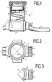
- Fig. 1 shows the side view of a feed and Distribution pipe 1 in a schematic representation. Then the feed and distribution pipe 1 in essentially from a base part 3, a manifold 2, a cover 6.
- the base part 3 consists of four base segments 10, each with different dimensions Pipe socket 4 are attached (Fig. 2 and 3).
- the pipe socket 4 of a base segment 10 according to FIG. 3 can have different diameters. It can both different pipe socket 4 and a different number of pipe sockets 4 in a segment 10 may be provided.
- the base segments 10 are by sealing elements 15 waterproof sealed.
- Pipe socket 4 which initially as a reserve socket not used, also do not need to be cut open and sealed.
- the base part 3 with the pipe socket 4 is used in Soil as an anchor against floating for the whole Intake and distribution pipe 1 for groundwater.
- the base part 3 is provided with base lugs 14 (Fig. 2,3), which enlarge the lower plinth space and a helical routing of the cables as a reserve cable length 8 to facilitate distributor 5.
- base lugs 14 Fig. 2,3
- a helical routing of the cables occurs Spiral interior 9, in the electronic or optoelectronic accessories such as multiplexers below of the distributor 5 can be introduced.
- the Cable coil 8 allows the distributor to be removed 5 without bending the cables excessively, which is special is important when wiring with fiber optic cables.
- the distributor pipe 2 is in the base part 3 from above used.
- the base part 3 is below by a Tension strap 12 secured (Fig. 1). It will be upstairs Base part 3 through in a groove 13 of the base part 3 pressed tube 2 held together (Fig. 2) and with a waterproof adhesive with the pipe 2 connected waterproof.
- the cover 6 is labyrinth-like with a not shown Formed edge of the manifold 2nd closed at the top water and insect proof.
- the distributor 5 is just below the cover 6 arranged easily accessible on a pad 11 and can be arbitrary, preferably circular be.
Landscapes
- Engineering & Computer Science (AREA)
- Life Sciences & Earth Sciences (AREA)
- Environmental & Geological Engineering (AREA)
- Hydrology & Water Resources (AREA)
- General Life Sciences & Earth Sciences (AREA)
- Mining & Mineral Resources (AREA)
- Paleontology (AREA)
- Civil Engineering (AREA)
- General Engineering & Computer Science (AREA)
- Structural Engineering (AREA)
- Laying Of Electric Cables Or Lines Outside (AREA)
Abstract
Description
Die Erfindung bezieht sich auf ein Einzugs- und Verteilerrohr für die Telekommunikations- und Datentechnik, insbesondere zum Einbringen in Kabelgräben.The invention relates to a feed and distribution pipe for telecommunications and data technology, especially for installation in cable trenches.
In den bestehenden Ortskabelnetzen sind an den Kreuzungs- und Abzweigpunkten des Kabel-Rohrsystems Kabelschächte mit Kabelschachtabdeckungen vorgesehen, über die der Zugriff zu den Kabeln und Muffen besteht, um die Kabel in verschiedene Richtungen abzuzweigen und zu verteilen. Diese aus Betonelementen gestalteten, begehbaren Kabelschächte haben einen großen Platzbedarf und sind aufwendig in der Herstellung. Es wird Baukapazität benötigt und es bestehen in den Ballungszentren der Städte Schwierigkeiten, diese Kabelschächte platzmäßig unterzubringen.In the existing local cable networks are at the Crossing and branching points of the cable and pipe system Cable ducts provided with cable duct covers, which gives access to the cables and sleeves, to branch the cables in different directions and distribute. These made of concrete elements, walkable cable ducts have a large one Space requirements and are complex to manufacture. It construction capacity is required and there are in the Metropolitan areas have difficulties with this Space for cable ducts.
Der Erfindung liegt die Aufgabe zugrunde, ein für Kupfer- und für Glasfaser-Kabel gleichermaßen anwendbares Einzugs- und Verteilerrohr zu entwickeln, mit dem an den Kreuzungs- und Abzweigpunkten des Kabel-Rohrsystems der Telekommunikations- und Datentechnik der Zugriff zu Kabeln, Muffen, Verteilern und gegebenenfalls elektronischen Einrichtungen mit geringem Aufwand zuverlässig gewährleistet wird.The invention has for its object a for Copper and fiber optic cables alike develop applicable feed and distribution pipe, with the at the intersection and branch points of the Telecommunication and cable system Data technology access to cables, sleeves, distributors and possibly electronic devices little effort is reliably guaranteed.
Die Lösung dieser Aufgabe ergibt sich aus den Merkmalen des Anspruches 1. Das erfindungsgemäße Einzugs- und Verteilerrohr besteht aus einem Sockelteil mit mehreren, vorzugsweise vier Segmenten, die mit Rohrstutzen zum Anmuffen der handelsüblichen Kabelrohre versehen sind, und aus einem Verteilerrohr mit Deckel, in welches ein Verteiler, Kabel-Reservelängen und elektronische Einrichtungen eingebracht werden können. Das Einzugs- und Verteilerrohr ist den Abmessungen der bestehenden Kabelgräben angepaßt und erfordert nur einen geringen Platzbedarf und wenig Erd- bzw. Bauarbeiten und kann der Anzahl der Kabel und der Tiefe des Grabens angepaßt vorgefertigt und montiert werden.The solution to this problem results from the features of claim 1. The collection and Manifold consists of a base part with several, preferably four, segments with Pipe socket for fitting the commercially available Cable pipes are provided, and from a distribution pipe with cover, in which a distributor, spare cable lengths and introduced electronic devices can be. The feed and distribution pipe is the Adapted dimensions of the existing cable trenches and requires little space and little Earthworks or construction work and can be the number of cables prefabricated and adapted to the depth of the trench and to be assembled.
Die gerade oder schräg in das Sockelteil eingesetzten Rohrstutzen erlauben das leichte Einziehen der Kabel mit runden Gleitflächen bei großem Biegeradius und gewährleisten eine gute Erreichbarkeit der Kabel beim Einfädeln mit der Hand oder Zugmitteln. Die Herstellung der Sockelsegmente kann in vielen Ausführungsformen mit keinem oder mit einer Vielzahl von Rohrstutzen auf Spritzmaschinen mit Werkzeugen ohne Schieber erfolgen. Die verschiedenartig ausgeführten Sockelsegmente können beliebig zusammengesetzt werden. Die Sockelsegmente können durch Dichtungsmittel wie Dichtungsschnüre wasserdicht miteinander verbunden werden.The straight or slanted in the base part Pipe sockets allow the cables to be pulled in easily with round sliding surfaces with a large bending radius and ensure good accessibility of the cables when Threading by hand or pulling means. The Manufacturing the base segments can be done in many Embodiments with no or with a multitude of pipe sockets on injection molding machines with tools done without slider. The different executed base segments can be any be put together. The base segments can waterproof by sealing means such as sealing cords be connected to each other.
Weitere vorteilhafte Ausgestaltungen der Erfindung ergeben sich aus den Unteransprüchen.Further advantageous embodiments of the invention result from the subclaims.
Die Erfindung ist nachfolgend anhand eines in den Zeichnungen dargestellten Ausführungsbeispieles eines Einzugs- und Verteilerrohrs näher erläutert. Es zeigen:
- Fig. 1
- die schematische Seitenansicht eines Einzugs- und Verteilerrohrs,
- Fig. 2
- die Draufsicht auf das Sockelteil des Einzugs- und Verteilerrohrs nach Fig. 1 und
- Fig. 3
- die schematische Draufsicht auf ein Sockelsegment des Einzugs- und Verteilerrohrs nach den Fig. 1 und 2.
- Fig. 1
- the schematic side view of a feed and distribution pipe,
- Fig. 2
- the top view of the base part of the feed and distribution pipe according to Fig. 1 and
- Fig. 3
- the schematic plan view of a base segment of the pull-in and distribution pipe according to FIGS. 1 and 2.
Die Fig. 1 zeigt die Seitenansicht eines Einzugs- und
Verteilerrohres 1 in einer schematischen Darstellung.
Danach besteht das Einzugs- und Verteilerrohr 1 im
wesentlichen aus einem Sockelteil 3, einem Verteilerrohr
2, einem Deckel 6.Fig. 1 shows the side view of a feed and
Distribution pipe 1 in a schematic representation.
Then the feed and distribution pipe 1 in
essentially from a
Das Sockelteil 3 besteht aus vier Sockelselsegmenten
10, an die jeweils unterschiedlich dimensionierte
Rohrstutzen 4 angesetzt sind (Fig. 2 und 3).The
Die Rohrstutzen 4 eines Sockelsegmentes 10 nach Fig. 3
können unterschiedliche Durchmesser aufweisen. Es
können sowohl unterschiedliche Rohrstutzen 4 als auch
eine unterschiedliche Anzahl von Rohrstutzen 4 in
einem Segment 10 vorgesehen sein.The
Die Sockelsegmente 10 sind durch Dichtungselemente 15
wasserdicht verfugt.The
Rohrstutzen 4, welche als Reservestutzen zunächst
nicht benutzt werden, brauchen auch nicht
aufgeschnitten und abgedichtet zu werden.
Das Sockelteil 3 mit den Rohrstutzen 4 dient im
Erdreich als Anker gegen Aufschwimmen für das gesamte
Einzugs- und Verteilerrohr 1 bei Grundwasser.The
Das Sockelteil 3 ist mit Sockelansätzen 14 versehen
(Fig. 2,3), die den unteren Sockelraum vergrößern und
ein wendelförmiges Führen der Kabel als Kabel-Reservelänge
8 zum Verteiler 5 erleichtern. Durch das
wendelförmige Führen der Kabel entsteht ein
Wendelinnenraum 9, in den elektronisches oder
optoelektronisches Zubehör wie Multiplexer unterhalb
des Verteilers 5 eingebracht werden können. Die
Kabelwendel 8 erlaubt das Herausnehmen des Verteilers
5 ohne die Kabel übermäßig zu biegen, was besonders
bei der Beschaltung mit Glasfaser-Kabel wichtig ist.The
In das Sockelteil 3 ist von oben das Verteilerrohr 2
eingesetzt. Das Sockelteil 3 ist unten durch ein
Spannband 12 gesichert (Fig. 1). Oben wird das
Sockelteil 3 durch das in eine Nut 13 des Sockelteils
3 eingedrückte Rohr 2 zusammengehalten (Fig. 2) und
durch einen wasserfesten Kleber mit dem Rohr 2
wasserdicht verbunden.The
Der Deckel 6 ist mit einem nicht dargestellten labyrinthartigen
Rand ausgebildet, der das Verteilerrohr 2
nach oben wasser- und insektendicht verschließt.The
Der Verteiler 5 ist dicht unterhalb des Deckels 6
leicht zugänglich auf einer Auflage 11 angeordnet und
kann beliebig, vorzugsweise kreisförmig ausgebildet
sein. The
- 0101
- Einzugs- und VerteilerrohrFeed and distribution pipe
- 0202
- VerteilerrohrManifold
- 0303
- SockelteilBase part
- 0404
- RohrstutzenPipe socket
- 0505
- VerteilerDistributor
- 0606
- Deckelcover
- 0707
- KabelrohrCable duct
- 0808
- Kabel-ReservelängeReserve cable length
- 0909
- Raumroom
- 1010th
- SockelsegmentBase segment
- 1111
- AuflageEdition
- 1212th
- SpannbandStrap
- 1313
- NutGroove
- 1414
- SockelansatzBase approach
- 1515
- DichtungselementSealing element
Claims (9)
dadurch gekennzeichnet, daß
ein Sockelteil (3) mit eingesetzten oder angeformten Rohrstutzen (4) zum Anmuffen von Kabelrohren (7) mit einem Verteilerrohr (2) zur Aufnahme eines Kabelverteilers (5) und einer Kabel-Reservelänge (8) wasserdicht verbunden ist, wobei das Verteilerrohr (2) durch einen Deckel (6) verschlossen ist.Pull-in and distribution pipe for telecommunications and data technology, especially for insertion in cable trenches,
characterized in that
a base part (3) with inserted or molded pipe sockets (4) for connecting cable ducts (7) to a distributor pipe (2) for receiving a cable distributor (5) and a cable reserve length (8), the distributor pipe (2 ) is closed by a cover (6).
Applications Claiming Priority (2)
| Application Number | Priority Date | Filing Date | Title |
|---|---|---|---|
| DE19736705 | 1997-08-20 | ||
| DE1997136705 DE19736705C2 (en) | 1997-08-20 | 1997-08-20 | Feed and distribution pipe for telecommunications and data technology |
Publications (1)
| Publication Number | Publication Date |
|---|---|
| EP0908994A1 true EP0908994A1 (en) | 1999-04-14 |
Family
ID=7839932
Family Applications (1)
| Application Number | Title | Priority Date | Filing Date |
|---|---|---|---|
| EP98114148A Withdrawn EP0908994A1 (en) | 1997-08-20 | 1998-07-29 | Feeding and distribution tube for the telecommunication and data technology |
Country Status (2)
| Country | Link |
|---|---|
| EP (1) | EP0908994A1 (en) |
| DE (1) | DE19736705C2 (en) |
Cited By (3)
| Publication number | Priority date | Publication date | Assignee | Title |
|---|---|---|---|---|
| GB2349233A (en) * | 1999-04-22 | 2000-10-25 | Bowthorpe Plc | Cable splice enclosure with angled cable port |
| WO2006127457A1 (en) * | 2005-05-25 | 2006-11-30 | Adc Telecommunications, Inc. | Underground enclosure mounting system |
| EP4196834A4 (en) * | 2020-08-14 | 2024-08-07 | CommScope Technologies LLC | Fiber optic enclosure with a side cable entrance |
Families Citing this family (5)
| Publication number | Priority date | Publication date | Assignee | Title |
|---|---|---|---|---|
| EP1484828A1 (en) * | 2003-06-02 | 2004-12-08 | IED Industrial Engineering & Design GmbH | Cable chamber for cable ducts or hoses laid underground in a local cable duct network system |
| NL2002004C (en) * | 2008-09-22 | 2010-03-23 | Attema Kunststoffenind | HOLDER. |
| NL2002006C (en) * | 2008-09-22 | 2010-03-23 | Attema Kunststoffenind | LASH HOUSE. |
| DE102010026397A1 (en) * | 2010-07-07 | 2012-01-12 | Gabo Systemtechnik Gmbh | Storage container, underground pipeline and system for the underground arrangement of pipeline storage |
| EP3660992A1 (en) * | 2018-11-29 | 2020-06-03 | Hauff-Technik GmbH & Co. KG | Connection housing device |
Citations (4)
| Publication number | Priority date | Publication date | Assignee | Title |
|---|---|---|---|---|
| US4709980A (en) * | 1985-08-02 | 1987-12-01 | Coastal Engineered Products Company, Inc. | Buried-cable junction enclosure with cable-storage vault |
| EP0532980A2 (en) * | 1991-09-17 | 1993-03-24 | Siemens Aktiengesellschaft | Sleeve with cap for receiving cable splices |
| EP0732790A1 (en) * | 1995-03-13 | 1996-09-18 | Kawasaki Steel Corporation | Compact cable unit |
| WO1997019377A1 (en) * | 1995-11-22 | 1997-05-29 | Bowthorpe Plc | Splice arrangements for optical fibre cables |
Family Cites Families (2)
| Publication number | Priority date | Publication date | Assignee | Title |
|---|---|---|---|---|
| DE4140701C1 (en) * | 1991-12-10 | 1992-12-10 | Siemens Ag, 8000 Muenchen, De | Buried container e.g. for fibre=optic cable junction - is partially held in shaft and has removable lid and lifting arrangement to allow easy working access e.g. for further splicing |
| GB9611154D0 (en) * | 1996-05-29 | 1996-07-31 | As & A Consultants Limited As | Live wire installation of electrical apparatus |
-
1997
- 1997-08-20 DE DE1997136705 patent/DE19736705C2/en not_active Expired - Fee Related
-
1998
- 1998-07-29 EP EP98114148A patent/EP0908994A1/en not_active Withdrawn
Patent Citations (4)
| Publication number | Priority date | Publication date | Assignee | Title |
|---|---|---|---|---|
| US4709980A (en) * | 1985-08-02 | 1987-12-01 | Coastal Engineered Products Company, Inc. | Buried-cable junction enclosure with cable-storage vault |
| EP0532980A2 (en) * | 1991-09-17 | 1993-03-24 | Siemens Aktiengesellschaft | Sleeve with cap for receiving cable splices |
| EP0732790A1 (en) * | 1995-03-13 | 1996-09-18 | Kawasaki Steel Corporation | Compact cable unit |
| WO1997019377A1 (en) * | 1995-11-22 | 1997-05-29 | Bowthorpe Plc | Splice arrangements for optical fibre cables |
Cited By (5)
| Publication number | Priority date | Publication date | Assignee | Title |
|---|---|---|---|---|
| GB2349233A (en) * | 1999-04-22 | 2000-10-25 | Bowthorpe Plc | Cable splice enclosure with angled cable port |
| WO2006127457A1 (en) * | 2005-05-25 | 2006-11-30 | Adc Telecommunications, Inc. | Underground enclosure mounting system |
| US7330625B2 (en) | 2005-05-25 | 2008-02-12 | Adc Telecommunications, Inc. | Underground enclosure mounting system |
| US7483617B2 (en) | 2005-05-25 | 2009-01-27 | Adc Telecommunications, Inc. | Underground enclosure mounting system |
| EP4196834A4 (en) * | 2020-08-14 | 2024-08-07 | CommScope Technologies LLC | Fiber optic enclosure with a side cable entrance |
Also Published As
| Publication number | Publication date |
|---|---|
| DE19736705C2 (en) | 1999-06-24 |
| DE19736705A1 (en) | 1999-03-04 |
Similar Documents
| Publication | Publication Date | Title |
|---|---|---|
| DE69609447T2 (en) | Cable splice cover | |
| EP0875015B1 (en) | Cable joint for optical fibres with splicing cassettes and overlength loops | |
| DE3640226C2 (en) | ||
| DE60123059T2 (en) | BUILDINGS TO BE USED IN BUILDINGS TO CONNECT BETWEEN OPTICAL FIBERS AND WORKPLACES | |
| CH653818A5 (en) | ENCLOSURE TO PROTECT SPLICE BETWEEN AT LEAST TWO CABLES. | |
| DE19736705C2 (en) | Feed and distribution pipe for telecommunications and data technology | |
| EP0875777A2 (en) | Cable sleeve for a fibre optic cable | |
| DE19640816C2 (en) | Sealing element | |
| EP2993750A2 (en) | Frame assembly for a fiber management unit | |
| DE19925149C2 (en) | harness | |
| EP2240985B1 (en) | Installation box, in particular distribution box for surface wiring | |
| DE3545517C2 (en) | ||
| DE4439853A1 (en) | Junction unit for optic fibres | |
| DE69007612T2 (en) | Splice sleeve for fiber optic cables. | |
| DE102019000304A1 (en) | casing | |
| DE69800078T2 (en) | Coupling with eccentric parts, especially for housings for electrical installation | |
| DE19628442C1 (en) | Connecting socket insert for light conducting cable for surface and under plaster mounting | |
| DE2739496A1 (en) | ELECTRIC SOCKETS | |
| DE29904357U1 (en) | Installation box for fiber optic cables | |
| DE102024125456B3 (en) | Enclosures, for example for a fiber optic network distributor or junction box, and methods for installing an enclosure | |
| DE3436073A1 (en) | Coupling piece for a cable duct | |
| DE2926078A1 (en) | Flush socket for concrete construction work - is formed in two parts with break-away wall section and lead openings | |
| EP0677854B1 (en) | Jacketed electrical cable | |
| DE102020003258A1 (en) | Use of a junction box | |
| EP1222721B1 (en) | Guiding arc |
Legal Events
| Date | Code | Title | Description |
|---|---|---|---|
| PUAI | Public reference made under article 153(3) epc to a published international application that has entered the european phase |
Free format text: ORIGINAL CODE: 0009012 |
|
| AK | Designated contracting states |
Kind code of ref document: A1 Designated state(s): AT BE CH CY DE DK ES FI FR GB GR IE IT LI LU MC NL PT SE |
|
| AX | Request for extension of the european patent |
Free format text: AL;LT;LV;MK;RO;SI |
|
| AKX | Designation fees paid | ||
| STAA | Information on the status of an ep patent application or granted ep patent |
Free format text: STATUS: THE APPLICATION IS DEEMED TO BE WITHDRAWN |
|
| 18D | Application deemed to be withdrawn |
Effective date: 19991014 |
|
| REG | Reference to a national code |
Ref country code: DE Ref legal event code: 8566 |