EP0908809A1 - Umgossener Ventilkörper insbesondere für ein Thermostatventil und Thermostatventil damit - Google Patents
Umgossener Ventilkörper insbesondere für ein Thermostatventil und Thermostatventil damit Download PDFInfo
- Publication number
- EP0908809A1 EP0908809A1 EP98402434A EP98402434A EP0908809A1 EP 0908809 A1 EP0908809 A1 EP 0908809A1 EP 98402434 A EP98402434 A EP 98402434A EP 98402434 A EP98402434 A EP 98402434A EP 0908809 A1 EP0908809 A1 EP 0908809A1
- Authority
- EP
- European Patent Office
- Prior art keywords
- insert
- flange
- region
- coating
- valve
- Prior art date
- Legal status (The legal status is an assumption and is not a legal conclusion. Google has not performed a legal analysis and makes no representation as to the accuracy of the status listed.)
- Granted
Links
Images

Classifications
-
- F—MECHANICAL ENGINEERING; LIGHTING; HEATING; WEAPONS; BLASTING
- F01—MACHINES OR ENGINES IN GENERAL; ENGINE PLANTS IN GENERAL; STEAM ENGINES
- F01P—COOLING OF MACHINES OR ENGINES IN GENERAL; COOLING OF INTERNAL-COMBUSTION ENGINES
- F01P7/00—Controlling of coolant flow
- F01P7/14—Controlling of coolant flow the coolant being liquid
- F01P7/16—Controlling of coolant flow the coolant being liquid by thermostatic control
-
- G—PHYSICS
- G05—CONTROLLING; REGULATING
- G05D—SYSTEMS FOR CONTROLLING OR REGULATING NON-ELECTRIC VARIABLES
- G05D23/00—Control of temperature
- G05D23/01—Control of temperature without auxiliary power
- G05D23/02—Control of temperature without auxiliary power with sensing element expanding and contracting in response to changes of temperature
- G05D23/021—Control of temperature without auxiliary power with sensing element expanding and contracting in response to changes of temperature the sensing element being a non-metallic solid, e.g. elastomer, paste
- G05D23/022—Control of temperature without auxiliary power with sensing element expanding and contracting in response to changes of temperature the sensing element being a non-metallic solid, e.g. elastomer, paste the sensing element being placed within a regulating fluid flow
Definitions
- the invention relates to valves comprising a insert and a molded coating for example of material elastic, in particular the watertight valves for cooling circuit regulation thermostats motor vehicle engines, as well as thermostats fitted with such a valve.
- valves are currently produced by overmolding of an elastomer on a metal insert, after gluing the insert so that it resists tearing off and taking off by the flow of coolant that circulates at high temperature and at high speed when the valve is very little open.
- valves are expensive because the sizing must be done very carefully, and the overmolding should. be produced on specific presses including automation is difficult due to the breakdown of flow in the production process due to the operation gluing.
- the object of the invention is to remedy these disadvantages and for this purpose relates to a valve in particular for thermostat, comprising an insert and a coating molded integral with the insert, this insert comprising at minus a region of generally cylindrical shape to a end of which a span for a thermostatic element, this range extending towards outside the cylindrical region, a flange connected to this scope also extending outwards, and a flange extending the flange, valve characterized in that that the coating at least partially envelops the insert from the outside, covering it at least from a face of the staff turned in opposite direction to that in which the cylindrical region extends, which it overlaps at least partially, and at least up to a face of the flange which is on the side of this region cylindrical, to resist takeoff and removal by a fluid passing through the thermostat.
- the insert is surrounded on almost its entire surface by the coating material, in avoids the need to glue the insert and one can part increase the production rate and on the other hand make valves with the coating material elastic or low hardness is not rubber.
- the invention also relates to a thermostat.
- a thermostat comprising a valve as defined above, an element of a housing comprising a seat for the valve, an element thermostatic comprising a movable part having a collar, and an elastic member to recall the valve to the seat, thermostat characterized in that the movable part of the thermostatic element is fitted hard in the valve, the coating being kept under pressure against the insert between the elastic member and a shoulder of the collar.
- the coating is kept in pressure against the insert, on one side by an organ elastic such as a coil spring and on the other by the collar of the movable part of the element thermostatic, the resistance of the coating to tearing in operation under conditions severe, is further increased.
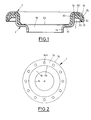
- the valve of Figure 1 consists of a metal or synthetic material insert 1 having good chemical and mechanical resistance and a coating 2 of elastic material or of low hardness, overmolded without prior gluing of the insert.
- Insert 1 is presented here in the form of a section of sheet metal tube comprising two generally cylindrical regions 11, 13 of diameters different extending longitudinally end-to-end-around of a common central axis and connected by a shoulder 12. While the smaller region diameter 11 constitutes one of the two end regions of the valve, the region of larger diameter 13 is extended radially outwards, to constitute the other end of the insert, by a shaped flange 14 circular crown itself extended by a rim 15 folded back to the first end region of the insert; this rim 15 has a general shape approximately frustoconical whose diameter increases in going towards the first end, up to its own free end which ends in a bevel.
- the flange 14 has perforations 141 circular angularly distributed evenly, for example twelve perforations distributed at 30 degrees.
- Coating 2 follows the shape of the insert by continuously covering from the face of the shoulder 12 inside the insert, which it preferably covers only partially, on an outer part of its surface, up to the face of the flange 14 which is turned on the side of regions of generally cylindrical shape 11, 13 of the insert, which it completely covers until it contact with the outer surface of region 13 of larger diameter.
- the outer surfaces of the coating On the surfaces of the insert that covers this coating, the outer surfaces of the coating have approximately the same shape as the corresponding surfaces of the insert, but with connection radii may be different.
- an outer surface is approximately cylindrical, the free end of the frustoconical edge of the coating.
- coating 2 does not cover the face of the shoulder 12 inside the insert 1 only on a outer part of its surface, it has a hole central 24 of diameter slightly larger than the diameter the central hole 16 of the insert, allowing expansion radial of the elastic material which constitutes it, when is subjected to axial compression.
- the joint plane of the coating mold is located at the level of the coating region which covers the face of the flange 14 of the insert which is on the side of the regions of general cylindrical shape 11, 13 thereof.
- the functional region of the valve is a region approximately frustoconical 25 of the coating, which covers the outer face of the frustoconical rim 15 of the insert.
- the housing element 3 of the thermostat of the figure 3, made of synthetic material, has a bottom externally domed provided internally with a boss 31 having a housing for a fixed part 41 a thermostatic element 4 bearing on the bottom of the housing.
- This housing element comprises a seat 32 of general frustoconical shape, for valve 1, 2, the diameter increases with distance from the housing for the fixed part of the thermostatic element, i.e. approaching the open end of the element of case 3; this open end has a rim support 33 for the movable element thermostatic, projecting radially towards inside the housing element.
- the movable part 42 of the thermostatic element comprises a body 421 of generally cylindrical shape, the opposite of the fixed part 41 housed in the boss of the bottom of the housing element, and a collar 422 valve support.
- the valve is threaded around the body of the element thermostatic 4 and the flange 422 of this element is "Hard fitting" in the coating region which covers the interior surface of the region of great diameter 13 of insert 1; moreover, the shoulder of the collar 422 which connects the periphery thereof to the body 421 is pressed against the region of coating 2 which covers the shoulder 12 of the insert, playing the role of worn for the thermostatic element, while the body is fitted (also fitted hard) in the region of smallest diameter 11 of the insert.
- the valve is applied against the seat frustoconical 32 of the housing element by a member elastic 5 in the form of a helical spring tablet with one end resting against the region of the coating which covers the face of the flange 14 of the insert which is on the side of the regions of general shape cylindrical thereof and the other end of which is in support on a washer 6 threaded around the body of the moving part of the thermostatic element so that this movable part can slide inside this washer, supported by the support flange 33 of the housing element.
- a member elastic 5 in the form of a helical spring tablet with one end resting against the region of the coating which covers the face of the flange 14 of the insert which is on the side of the regions of general shape cylindrical thereof and the other end of which is in support on a washer 6 threaded around the body of the moving part of the thermostatic element so that this movable part can slide inside this washer, supported by the support flange 33 of the housing element.
- the elastic coating 2 is kept in pressure against the insert 1 on one side by the coil spring 5, and on the other by the collar 422 of the movable part of the thermostatic element, this which provides a more hermetic seal, in particular between the valve and the thermostatic element.
- Thermostat operation does not differ in principle that of valve thermostats conventional, since with any increase in the temperature corresponds to an extension movement of the thermostatic element 4 against the force exerted by the spring 5 on the valve 1, 2, and a detachment of the valve relative to seat 32 of the housing element 3, then, when the temperature decreases, the spring returns the valve to the seat.
- This structure allows to use, for constitute the coating, ie conventional elastomers, without having to glue the metal insert, i.e. thermoplastic elastomers (TPE) molded directly on standard machines for plastic molding, because TPE does not require vulcanization, which allows to get manufacturing cycle times very lower than those of conventional elastomer molding, or else thermoplastics of low hardness; of more, automation can be achieved very simply without flow break in the process manufacturing.
- TPE thermoplastic elastomers
- the valve comprises an insert 1 and an over-molded coating 2 secured thereto, this insert comprising at least one region of general shape cylindrical at one end of which a reach 12 for a thermostatic element 4.
- This reach 12 extends outward from the cylindrical region 11, a flange 14 is connected to the bearing 12 also extending outwards, and a flange 15 extends the flange 14.
- coating 2 partially envelops insert 1 from the outside, covering it continuously at less from one face of the scope 12 turned in the direction opposite to that in which the cylindrical region extends 11 that it covers at least partially, and at least up to one face of the flange 14 which is on the side of the cylindrical region 11.
- this embodiment has only one region of generally cylindrical shape 11. It follows that the scope 12 is not a shoulder connecting two regions cylindrical, and that this bearing 12 and the flange 14 are not not themselves linked through a region cylindrical, but that they are in direct connection, the bearing 12 also having a rounded connection with the region of cylindrical shape 11.
- coating 2 completely covers the face of the litter 12 turned in the opposite direction to that in which extends the cylindrical region 11, and it envelops insert 1 from the outside beyond the face of the flange 14 which is on the side of region 11, since it even covers in full the face of the staff 12 which is on the side of this region 11, and ends against the latter.
- the end of the rim 15 ends with a song perpendicular to its faces, and the coating follows this shape by covering this outside edge of the insert 1.
- the coating is approximately thick constant over its entire extent.
- the thermostat includes as previously, in addition to the valve, a housing element comprising a seat for the valve, an element thermostatic 4 comprising a movable part 42 provided a collar 422, and an elastic member 5 for return the valve to the seat. Likewise, the moving part of the thermostatic element 4 is fitted into the valve, coating 2 being kept under pressure against the insert between the elastic member and a shoulder of the collar.
Landscapes
- Engineering & Computer Science (AREA)
- Physics & Mathematics (AREA)
- Chemical & Material Sciences (AREA)
- Combustion & Propulsion (AREA)
- Mechanical Engineering (AREA)
- General Engineering & Computer Science (AREA)
- Fluid Mechanics (AREA)
- General Physics & Mathematics (AREA)
- Automation & Control Theory (AREA)
- Temperature-Responsive Valves (AREA)
Applications Claiming Priority (2)
| Application Number | Priority Date | Filing Date | Title |
|---|---|---|---|
| FR9712711 | 1997-10-10 | ||
| FR9712711A FR2769680B1 (fr) | 1997-10-10 | 1997-10-10 | Clapet surmoule, notamment pour thermostat, et thermostat muni d'un tel clapet |
Publications (2)
| Publication Number | Publication Date |
|---|---|
| EP0908809A1 true EP0908809A1 (de) | 1999-04-14 |
| EP0908809B1 EP0908809B1 (de) | 2003-07-16 |
Family
ID=9512108
Family Applications (1)
| Application Number | Title | Priority Date | Filing Date |
|---|---|---|---|
| EP19980402434 Expired - Lifetime EP0908809B1 (de) | 1997-10-10 | 1998-10-02 | Umgossener Ventilkörper insbesondere für ein Thermostatventil und Thermostatventil damit |
Country Status (4)
| Country | Link |
|---|---|
| EP (1) | EP0908809B1 (de) |
| DE (1) | DE69816396T2 (de) |
| ES (1) | ES2203905T3 (de) |
| FR (1) | FR2769680B1 (de) |
Cited By (6)
| Publication number | Priority date | Publication date | Assignee | Title |
|---|---|---|---|---|
| EP1219873A1 (de) * | 2000-12-29 | 2002-07-03 | Vernet S.A. | Eingepresste Ventildichtung und Herstellungsverfahren für dieselbe |
| EP1246038A3 (de) * | 2001-03-12 | 2002-10-09 | Dura France | Vorrichtung zum Verschliessen einer Fluidrohrleitung |
| EP1717499A1 (de) * | 2005-04-27 | 2006-11-02 | Gustav Wahler GmbH u. Co.KG | Ventil |
| WO2010052666A1 (en) * | 2008-11-06 | 2010-05-14 | Itw Automotive Products Gmbh | Thermostat valve |
| CN112012824A (zh) * | 2019-05-30 | 2020-12-01 | 江苏美多汽车配件有限公司 | 一种节温器罩 |
| FR3103021A1 (fr) * | 2019-11-13 | 2021-05-14 | Vernet | Dispositif thermostatique de régulation de la circulation d’un fluide, ainsi que vanne thermostatique correspondante et procédé de fabrication d’un tel dispositif |
Citations (4)
| Publication number | Priority date | Publication date | Assignee | Title |
|---|---|---|---|---|
| FR1460357A (fr) * | 1965-12-17 | 1966-11-25 | Dole Valve Co | Thermostat pour canalisation d'eau |
| EP0286810A1 (de) * | 1987-04-08 | 1988-10-19 | Gustav Wahler GmbH u. Co | Verfahren zum Herstellen eines Ventils, insbesondere eines thermostatischen Ventils |
| EP0485254A1 (de) * | 1990-11-05 | 1992-05-13 | Vernet | Mit einer Wachskapsel betriebener und mit einer Sicherheitsvorrichtung versehener Thermostat |
| EP0716367A2 (de) * | 1994-12-09 | 1996-06-12 | NIPPON THERMOSTAT Co., Ltd. | Thermisch gesteuertes Ventil |
-
1997
- 1997-10-10 FR FR9712711A patent/FR2769680B1/fr not_active Expired - Fee Related
-
1998
- 1998-10-02 DE DE69816396T patent/DE69816396T2/de not_active Expired - Fee Related
- 1998-10-02 EP EP19980402434 patent/EP0908809B1/de not_active Expired - Lifetime
- 1998-10-02 ES ES98402434T patent/ES2203905T3/es not_active Expired - Lifetime
Patent Citations (4)
| Publication number | Priority date | Publication date | Assignee | Title |
|---|---|---|---|---|
| FR1460357A (fr) * | 1965-12-17 | 1966-11-25 | Dole Valve Co | Thermostat pour canalisation d'eau |
| EP0286810A1 (de) * | 1987-04-08 | 1988-10-19 | Gustav Wahler GmbH u. Co | Verfahren zum Herstellen eines Ventils, insbesondere eines thermostatischen Ventils |
| EP0485254A1 (de) * | 1990-11-05 | 1992-05-13 | Vernet | Mit einer Wachskapsel betriebener und mit einer Sicherheitsvorrichtung versehener Thermostat |
| EP0716367A2 (de) * | 1994-12-09 | 1996-06-12 | NIPPON THERMOSTAT Co., Ltd. | Thermisch gesteuertes Ventil |
Cited By (14)
| Publication number | Priority date | Publication date | Assignee | Title |
|---|---|---|---|---|
| EP1219873A1 (de) * | 2000-12-29 | 2002-07-03 | Vernet S.A. | Eingepresste Ventildichtung und Herstellungsverfahren für dieselbe |
| FR2819035A1 (fr) * | 2000-12-29 | 2002-07-05 | Vernet Sa | Clapet a joint serti et procede de fabrication d'un tel clapet |
| US6698720B2 (en) | 2000-12-29 | 2004-03-02 | Vernet S.A. | Valve member with a crimped gasket, and a method of manufacturing such a member |
| EP1246038A3 (de) * | 2001-03-12 | 2002-10-09 | Dura France | Vorrichtung zum Verschliessen einer Fluidrohrleitung |
| EP1717499A1 (de) * | 2005-04-27 | 2006-11-02 | Gustav Wahler GmbH u. Co.KG | Ventil |
| US8827172B2 (en) | 2008-11-06 | 2014-09-09 | Itw Automotive Products Gmbh | Thermostat valve |
| WO2010052666A1 (en) * | 2008-11-06 | 2010-05-14 | Itw Automotive Products Gmbh | Thermostat valve |
| CN112012824A (zh) * | 2019-05-30 | 2020-12-01 | 江苏美多汽车配件有限公司 | 一种节温器罩 |
| FR3103021A1 (fr) * | 2019-11-13 | 2021-05-14 | Vernet | Dispositif thermostatique de régulation de la circulation d’un fluide, ainsi que vanne thermostatique correspondante et procédé de fabrication d’un tel dispositif |
| WO2021094186A1 (fr) | 2019-11-13 | 2021-05-20 | Vernet | Dispositif thermostatique de régulation de la circulation d'un fluide, ainsi que vanne thermostatique correspondante et procédé de fabrication d'un tel dispositif |
| CN114830059A (zh) * | 2019-11-13 | 2022-07-29 | 韦内特公司 | 一种调节流体循环的恒温装置及其适配的恒温阀,以及该恒温装置的制造方法 |
| US20220389857A1 (en) * | 2019-11-13 | 2022-12-08 | Vernet | Thermostatic device for regulating the circulation of a fluid, corresponding thermostatic valve and method for manufacturing such a device |
| CN114830059B (zh) * | 2019-11-13 | 2023-12-01 | 韦内特公司 | 一种调节流体循环的恒温装置及其适配的恒温阀,以及该恒温装置的制造方法 |
| US12092013B2 (en) | 2019-11-13 | 2024-09-17 | Vernet | Thermostatic device for regulating the circulation of a fluid, corresponding thermostatic valve and method for manufacturing such a device |
Also Published As
| Publication number | Publication date |
|---|---|
| FR2769680A1 (fr) | 1999-04-16 |
| EP0908809B1 (de) | 2003-07-16 |
| DE69816396T2 (de) | 2004-02-19 |
| ES2203905T3 (es) | 2004-04-16 |
| FR2769680B1 (fr) | 1999-12-31 |
| DE69816396D1 (de) | 2003-08-21 |
Similar Documents
| Publication | Publication Date | Title |
|---|---|---|
| EP0606028A1 (de) | Abgedichtete Verbindung zwischen einem Rohr und einem Endstück und deren Verfahren zur Herstellung | |
| FR2950036A1 (fr) | Dispositif de distribution de liquide | |
| EP1149011B1 (de) | Kugelgelenk, insbesondere kugelgelenk einer lenkung oder aufhängung für kraftfahrzeuge, und herstellungsverfahren einer lagerschale für ein solches kugelgelenk | |
| FR3026353A1 (fr) | Aerateur et vehicule comprenant un tel aerateur | |
| WO2017140637A1 (fr) | Dispositif de bouchage pour un col de récipient | |
| FR2787546A1 (fr) | Element de vanne et procede pour le fabriquer | |
| EP0908809B1 (de) | Umgossener Ventilkörper insbesondere für ein Thermostatventil und Thermostatventil damit | |
| FR2920851A1 (fr) | Dispositif de galet tendeur de courroie | |
| CA2186396C (fr) | Dispositif de conditionnement et de distribution | |
| FR2730537A1 (fr) | Manchon antivibratoire hydraulique et son procede de fabrication | |
| FR2645206A1 (fr) | Soupape a air pour pompe a diaphragme | |
| EP1648793A1 (de) | Fluidproduktabgabekopf und verwendung davon | |
| FR2460436A1 (fr) | Soupape electromagnetique a eau, a assistance hydraulique, pour le reglage du circuit d'eau, dans les installations de chauffage ou de climatisation pour vehicules automobiles | |
| FR2785222A1 (fr) | Procede de fabrication d'un obturateur, poussoir et tete de distribution incorporant un tel obturateur | |
| WO2007077361A2 (fr) | Buse de distribution de produit fluide, dispositif de distribution comprenant un telle buse et procede de fabrication | |
| FR2615581A1 (fr) | Dispositif d'etancheite pour poussoir de soupape precharge | |
| FR2700740A1 (fr) | Ensemble de jet pour lave-vitre de véhicule. | |
| FR2716656A1 (fr) | Agencement de palier étanche pour le montage d'un arbre d'un mécanisme d'entraînement d'un essuie-glace. | |
| EP1358414B1 (de) | Klappegehäuse mit eingerasteter manchette | |
| EP0825128A2 (de) | Element zur Befestigung einer Abgabevorrichtung an einem Behälterhals | |
| FR2600394A1 (fr) | Soupape pour installations de chauffage de vehicules | |
| WO2016169958A1 (fr) | Dispositif thermostatique de régulation de la circulation d'un fluide, ainsi que vanne thermostatique comprenant un tel dispositif | |
| FR2658872A1 (fr) | Perfectionnements apportes aux verins pour fluide sous pression. | |
| FR2881391A1 (fr) | Servomoteur pneumatique a sieges decales portes par deux douilles coulissantes | |
| WO2007074234A2 (fr) | Dispositif de distribution de produit fluide et buse de distribution pour un tel dispositif |
Legal Events
| Date | Code | Title | Description |
|---|---|---|---|
| PUAI | Public reference made under article 153(3) epc to a published international application that has entered the european phase |
Free format text: ORIGINAL CODE: 0009012 |
|
| AK | Designated contracting states |
Kind code of ref document: A1 Designated state(s): DE ES FR GB IT |
|
| AX | Request for extension of the european patent |
Free format text: AL;LT;LV;MK;RO;SI |
|
| 17P | Request for examination filed |
Effective date: 19990426 |
|
| AKX | Designation fees paid |
Free format text: DE ES FR GB IT |
|
| 17Q | First examination report despatched |
Effective date: 20020724 |
|
| GRAH | Despatch of communication of intention to grant a patent |
Free format text: ORIGINAL CODE: EPIDOS IGRA |
|
| GRAH | Despatch of communication of intention to grant a patent |
Free format text: ORIGINAL CODE: EPIDOS IGRA |
|
| GRAA | (expected) grant |
Free format text: ORIGINAL CODE: 0009210 |
|
| AK | Designated contracting states |
Designated state(s): DE ES FR GB IT |
|
| REG | Reference to a national code |
Ref country code: GB Ref legal event code: FG4D Free format text: NOT ENGLISH |
|
| REF | Corresponds to: |
Ref document number: 69816396 Country of ref document: DE Date of ref document: 20030821 Kind code of ref document: P |
|
| PGFP | Annual fee paid to national office [announced via postgrant information from national office to epo] |
Ref country code: GB Payment date: 20030926 Year of fee payment: 6 |
|
| PGFP | Annual fee paid to national office [announced via postgrant information from national office to epo] |
Ref country code: DE Payment date: 20031008 Year of fee payment: 6 |
|
| PGFP | Annual fee paid to national office [announced via postgrant information from national office to epo] |
Ref country code: ES Payment date: 20031014 Year of fee payment: 6 |
|
| PGFP | Annual fee paid to national office [announced via postgrant information from national office to epo] |
Ref country code: FR Payment date: 20031016 Year of fee payment: 6 |
|
| GBT | Gb: translation of ep patent filed (gb section 77(6)(a)/1977) |
Effective date: 20031117 |
|
| REG | Reference to a national code |
Ref country code: ES Ref legal event code: FG2A Ref document number: 2203905 Country of ref document: ES Kind code of ref document: T3 |
|
| PLBE | No opposition filed within time limit |
Free format text: ORIGINAL CODE: 0009261 |
|
| STAA | Information on the status of an ep patent application or granted ep patent |
Free format text: STATUS: NO OPPOSITION FILED WITHIN TIME LIMIT |
|
| 26N | No opposition filed |
Effective date: 20040419 |
|
| PG25 | Lapsed in a contracting state [announced via postgrant information from national office to epo] |
Ref country code: GB Free format text: LAPSE BECAUSE OF NON-PAYMENT OF DUE FEES Effective date: 20041002 |
|
| PG25 | Lapsed in a contracting state [announced via postgrant information from national office to epo] |
Ref country code: ES Free format text: LAPSE BECAUSE OF NON-PAYMENT OF DUE FEES Effective date: 20041004 |
|
| PG25 | Lapsed in a contracting state [announced via postgrant information from national office to epo] |
Ref country code: DE Free format text: LAPSE BECAUSE OF NON-PAYMENT OF DUE FEES Effective date: 20050503 |
|
| GBPC | Gb: european patent ceased through non-payment of renewal fee |
Effective date: 20041002 |
|
| PG25 | Lapsed in a contracting state [announced via postgrant information from national office to epo] |
Ref country code: FR Free format text: LAPSE BECAUSE OF NON-PAYMENT OF DUE FEES Effective date: 20050630 |
|
| REG | Reference to a national code |
Ref country code: FR Ref legal event code: ST |
|
| PG25 | Lapsed in a contracting state [announced via postgrant information from national office to epo] |
Ref country code: IT Free format text: LAPSE BECAUSE OF NON-PAYMENT OF DUE FEES Effective date: 20051002 |
|
| REG | Reference to a national code |
Ref country code: ES Ref legal event code: FD2A Effective date: 20041004 |