EP0908705A2 - Mass flowmeter - Google Patents
Mass flowmeter Download PDFInfo
- Publication number
- EP0908705A2 EP0908705A2 EP98117064A EP98117064A EP0908705A2 EP 0908705 A2 EP0908705 A2 EP 0908705A2 EP 98117064 A EP98117064 A EP 98117064A EP 98117064 A EP98117064 A EP 98117064A EP 0908705 A2 EP0908705 A2 EP 0908705A2
- Authority
- EP
- European Patent Office
- Prior art keywords
- coriolis
- mass flow
- coriolis line
- line
- flow meter
- Prior art date
- Legal status (The legal status is an assumption and is not a legal conclusion. Google has not performed a legal analysis and makes no representation as to the accuracy of the status listed.)
- Granted
Links
Images

Classifications
-
- G—PHYSICS
- G01—MEASURING; TESTING
- G01F—MEASURING VOLUME, VOLUME FLOW, MASS FLOW OR LIQUID LEVEL; METERING BY VOLUME
- G01F1/00—Measuring the volume flow or mass flow of fluid or fluent solid material wherein the fluid passes through a meter in a continuous flow
- G01F1/76—Devices for measuring mass flow of a fluid or a fluent solid material
- G01F1/78—Direct mass flowmeters
- G01F1/80—Direct mass flowmeters operating by measuring pressure, force, momentum, or frequency of a fluid flow to which a rotational movement has been imparted
- G01F1/84—Coriolis or gyroscopic mass flowmeters
- G01F1/8409—Coriolis or gyroscopic mass flowmeters constructional details
- G01F1/8413—Coriolis or gyroscopic mass flowmeters constructional details means for influencing the flowmeter's motional or vibrational behaviour, e.g., conduit support or fixing means, or conduit attachments
- G01F1/8418—Coriolis or gyroscopic mass flowmeters constructional details means for influencing the flowmeter's motional or vibrational behaviour, e.g., conduit support or fixing means, or conduit attachments motion or vibration balancing means
-
- G—PHYSICS
- G01—MEASURING; TESTING
- G01F—MEASURING VOLUME, VOLUME FLOW, MASS FLOW OR LIQUID LEVEL; METERING BY VOLUME
- G01F1/00—Measuring the volume flow or mass flow of fluid or fluent solid material wherein the fluid passes through a meter in a continuous flow
- G01F1/76—Devices for measuring mass flow of a fluid or a fluent solid material
- G01F1/78—Direct mass flowmeters
- G01F1/80—Direct mass flowmeters operating by measuring pressure, force, momentum, or frequency of a fluid flow to which a rotational movement has been imparted
- G01F1/84—Coriolis or gyroscopic mass flowmeters
- G01F1/845—Coriolis or gyroscopic mass flowmeters arrangements of measuring means, e.g., of measuring conduits
- G01F1/8468—Coriolis or gyroscopic mass flowmeters arrangements of measuring means, e.g., of measuring conduits vibrating measuring conduits
- G01F1/849—Coriolis or gyroscopic mass flowmeters arrangements of measuring means, e.g., of measuring conduits vibrating measuring conduits having straight measuring conduits
Definitions
- the invention relates to a mass flow meter based on the Coriolis principle works with an essentially straight Coriolis line carrying a flowing medium, with at least one of the Coriolis lines, the Coriolis line stimulating vibration generator, with at least one of the Coriolis line assigned Coriolis forces and / or Coriolis vibrations based on Coriolis forces measuring sensor and with a the Coriolis line receiving cylinder.
- the mass flow meter in question u. a. belong to at least one '' assigned '' vibration generator to the Coriolis line and at least one '' assigned '' sensor to the Coriolis line.
- the vibrator or the vibrators at least part of the vibration generator or part of the vibration generator and the transducer or transducers, in any case a part of the transducer or some of the sensors are connected to the Coriolis line.
- the expression "assigned" is used instead of the printout '' connected ''' - has been used.
- Mass flow meters with only one are increasingly used essentially straight Coriolis line through.
- Mass flow meters with one straight Coriolis line are simple in terms of mechanical construction.
- d. H. Can be produced at a comparatively low cost on the inner surfaces of the Coriolis line easy to edit, e.g. B. polishable, have a low pressure drop and are self-draining.
- Mass flow meters with only one straight Coriolis line are in spite of all Benefits problematic from a number of points of view.
- mass flow meters with only one Coriolis line Coupling of external interference stronger than with mass flow meters where operated two parallel Coriolis lines like a tuning fork be because in mass flow meters with only one Coriolis line the The center of gravity of the mass flow meter is not at rest.
- minimization the coupling of external disturbances, d. H. of vibrations in the surrounding Pipe system deal with DE 44 23 168 A1 and DE 196 32 500 A1.
- DE 197 32 605 A1 deals with the difficulty encountered in mass flow meters with a straight Coriolis line when measuring the extremely small phase difference in these mass flow meters between two measurement signals supplied by the transducers, which are proportional to the mass flow.
- the common requirements in industry for the measuring accuracy of mass flow meters require a resolution of the phase difference in the order of 1 ⁇ 10 -5 degrees.
- the invention is therefore based on the object of having a mass flow meter to provide a straight Coriolis line, the one in relation to the
- the nominal width of the Coriolis line has a shorter overall length than the known mass flow meters of the type in question.
- the previously derived and shown task is initially thereby solved that the Coriolis line via an inlet and an outlet in Recording cylinder is floating.
- the inlet and the outlet preferably either formed as a conically widening membrane or so Shaped, for example, curved, that the inlet and the outlet each can expand slightly, without the large tensions in the inlet Outlet or in the Coriolis line.
- the receiving cylinder and the components used for the floating mounting of the Coriolis line z. B. realize a mass flow meter that at a maximum mass flow of 300 kg / min only has a total length of 20 cm to a maximum of 30 cm.
- a particularly preferred embodiment of the mass flow meter according to the invention is characterized in that the receiving cylinder is the measuring device housing of the mass flow meter, preferably the receiving cylinder as a - relatively heavy - metal block with recesses for receiving Coriolis line, vibration generator and transducer is formed.
- This Embodiment of a mass flow meter according to the invention can without further be clamped between the flanges of adjacent pipes, whereby - of course within limits - a non-alignment of the Coriolis line with the adjacent ones Piping does not cause problems.
- the mass flow meter according to the invention can also, as in the prior art Technology actually common, in addition to the recording cylinder, a special measuring device housing have, which then expediently has flanges on both sides.
- a special measuring device housing In this embodiment there are between the Coriolis line and the measuring device housing two connecting lines are provided.
- the connecting lines are preferably at the inlet and outlet - approximately in the middle of the extension - connected. The wanted - '' limitless '' mobility of the Coriolis line is useful if the previously mentioned connecting lines as membranes are trained.
- the Measures that lead to the required vibrations of the Coriolis line also take into account that the Coriolis line in the receiving cylinder is floating. Not all measures known in the prior art for Generation of vibrations of the Coriolis line are also in the invention Mass flow meter applicable.
- the vibration generator Coriolis line to vibrate about a transverse to the longitudinal axis of the Coriolis line running vibration axis stimulates, - the vibration axis in the perpendicular to the longitudinal axis of the Coriolis line central plane of the mass flow meter lies.
- Mass flow meter the Coriolis line symmetrical to the perpendicular Longitudinal axis of the central plane running Coriolis line oscillates, however in each case 180 ° out of phase.
- Mass flow meter but also two vibrators in Arrange the longitudinal direction of the Coriolis line to the left and right of the center, whereby this then act on the Coriolis line in opposite phases have to.
- Piezo elements supported on spring elements can be used.
- the measures can. which are required to vibrate the Coriolis line, too be realized in such a way that the vibration generator the ends of the Coriolis line stimulate tumbling movements around the longitudinal axis of the Coriolis line and the wobbling movements of one end of the Coriolis line by 180 ° out of phase with the wobbling movements of the other end of the Coriolis line are.
- This type of vibration of the Coriolis line as for the previously described types of Coriolis line vibrations, that in the middle plane of the mass flow meter or the Coriolis line the center of the Coriolis line always remains stationary, as it were, all vibrations so take place around this center.
- At least the Coriolis line made of a material with a relatively low thermal expansion consists.
- Duplex, stainless steel, nickel in particular can be used as such a material.
- Titanium or carbon or glass fiber reinforced material can be used.
- the Coriolis line under tension or compression be arranged in the receiving cylinder.
- a tension then required if the mass flow meter according to the invention for particularly high temperatures should be suitable, in contrast, a compressive prestress when the mass flow meter according to the invention for particularly low Temperatures should be applicable.
- the Coriolis line is under tension arranged in the receiving cylinder, so initially with increasing temperature the tension is reduced and the compressive stress that occurs afterwards can be kept within permissible limits.
- the Coriolis line arranged under pressure in the receiving cylinder, so as the temperature drops, the pressure preload is reduced and then tensile stress can thus be kept within permissible limits.
- the mass flow meters shown in FIGS. 1 to 4 and in FIGS. 10 to 12 work, as is known, on the Coriolis principle and exist in their basic Construction from a straight Coriolis line carrying a flowing medium 1, from a Coriolis line 1 assigned, the Coriolis line 1 exciting Vibration generator 2 (Fig. 1 and 2) or two of the Coriolis line 1 assigned to the Coriolis line 1 exciting vibration generators 2, 3 (Fig. 3 and 4 and 10 to 12), from two Coriolis line 1 assigned Coriolis forces and / or detecting Coriolis vibrations based on Coriolis forces Transducers 4, 5 and from a Coriolis line 1 receiving Pick-up cylinder 6.
- the Coriolis line 1 via a conically widening inlet 7 and also one conically expanding outlet 8 floating in the receiving cylinder 6.
- this floating bearing is a deformation of the Coriolis line 1, as in the known mass flow meters from which the invention is based, not required; also a ⁇ practically limitless '' rigid Coriolis line 1 that floats is stored, can be so excited that in connection with one in the Coriolis line 1 flowing medium Coriolis forces are generated.
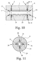
- FIGS. 10 and 11 show a particularly preferred embodiment of the mass flow meter according to the invention, characterized in that is that the receiving cylinder 6, the meter housing of the mass flow meter forms, the receiving cylinder 6 as - relatively heavier - Metal block with recesses for receiving Coriolis line 1, vibration generator 2 or vibration generator 2, 3 and transducers 4, 5 are formed is.
- This embodiment of the mass flow meter according to the invention can easily adjoin between the - not shown - flanges Pipelines are pinched, whereby - of course within limits - non-alignment the Coriolis line 1 with the adjacent pipes does not cause problems leads.
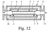
- FIGS. 1, 2 and 3 and FIGS. 10 and 11 show 4 and 12 an embodiment of a mass flow meter according to the invention, which is characterized in that in addition to the receiving cylinder 6 there is still a measuring device housing 9 and between the Coriolis line 1 and the measuring device housing 9 two connecting lines 10, 11 are provided are.
- the connecting lines 10, 11 are conical widening inlet 7 and the likewise conically widening outlet 8 - approximately in the middle of the extension - connected.
- the connecting lines 10, 11 as well as the inlet 7 and the outlet 8 are formed as membranes and the measuring device housing 9 is provided with flanges 12, 13.
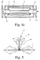
- FIG. 12 shows an embodiment of an inventive Mass flow meter, which is characterized in that the Inlet 7 and outlet 8 are arcuate. Through this execution can the inlet 7 and the outlet 8 each expand slightly without the Large voltages occur in, inlet 7 or in outlet 8, so that no large ones Voltages are transmitted to the Coriolis line 1.
- the Coriolis line can also be used 1 slightly expand yourself without causing great tension in it, since the inlet 7 and the outlet 8 also such an extension - of course to a small extent - allow.
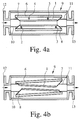
- FIG. 4 a shows the mass flow meter according to the invention in the static state, i.e. if there are no vibrations.
- Fig. 4 b shows the mass flow meter according to the invention with an existing excitation vibration
- Fig. 4 c the mass flow meter according to the invention at a existing Coriolis vibration. Both when there is an excitation vibration and also when there is a Coriolis vibration, the Coriolis line vibrates 1 in phase opposition to the receiving cylinder 6. Thus there is a balanced System in which very little energy and only slight vibrations occur the measuring device housing 9 is transmitted.
- Mass flow meters naturally take into account that the Coriolis line 1 is floating in the receiving cylinder 6.
- the vibration generator 2 (Fig. 1 and 2) or the vibration generator 2, 3 (Fig. 3, 4 and 12) to the Coriolis line 1 Vibrations around a transverse to the longitudinal axis of the Coriolis line 1 Excitation or excitation of the axis of vibration, - the axis of vibration in the perpendicular to the longitudinal axis of the Coriolis line 1 running center plane of the mass flow meter or the Coriolis line 1.
- the Coriolis line 1 therefore oscillates symmetrically to the perpendicular to the longitudinal axis of the Coriolis line 1 Middle plane, but each phase-shifted by 180 °.
- FIG. 1 shows an embodiment of the mass flow meter according to the invention, in which the vibration generator 2 between the receiving cylinder 6 and one transverse to the longitudinal axis of the Coriolis line 1, essentially in the longitudinal direction in the middle of the Coriolis line 1 attached pendulum 17 attacks.
- Pendulums 17 include a pendulum arm 18 and a compensation mass 19.
- the compensation mass 19 is chosen so that the natural frequency of the pendulum 17 as far possible with the natural frequency of the excitation vibration of the Coriolis line 1 matches.
- the vibration generator 2 engages between the receiving cylinder 6 and one transverse to the longitudinal axis of the Coriolis line 1, in the longitudinal direction attached essentially in the middle of the Coriolis line 1, with a compensation mass 20 provided torsion bar 21.
- Fig. 3 of a mass flow meter applies that two vibrators 2, 3 in the longitudinal direction of the Coriolis line 1, left and right of the center, are arranged, the vibration generator 2, 3 as piezo elements 24, 25 supported on spring elements 22, 23 are executed.
- Fig. 5 shows for the first embodiment of a mass flow meter according to the invention the Coriolis line 1 and the pendulum 17 in a schematic diagram for the excitation vibration. It can easily be seen that the Coriolis line 1 vibrations about a transverse to the longitudinal axis of the Coriolis line 1 Oscillation axis executes. The axis of vibration is perpendicular in FIG. 5 to the drawing level. From Fig. 5 it can also be seen that the Coriolis line 1 rather does not experience any deformation due to the floating bearing. Only the membranes indicated in FIG. 5 are practically deformed.
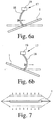
- 6 a) and 6 b) are to explain the pendulum 17 and on the Coriolis line 1 attacking forces the Coriolis line 1 and the pendulum 17 in different Phases of the excitation oscillation are shown.
- the deformations of the pendulum arm 18 each shown greatly enlarged.
- Fig. 7 shows in principle that of the excitation vibration shown in Fig. 5 superimposed Coriolis vibration caused by the flow of the flowing medium Coriolis forces generated by the Coriolis line 1 are excited.
- the Superposition of the Coriolis vibration shown in FIG. 7 leads to a measurement detectable phase difference of the oscillation of two points on the right and to the left of the center of the Coriolis line 1. This phase difference is the mass flow proportional since the Coriolis forces causing the phase difference are equal to Mass flow through the Coriolis line 1 are proportional.
Landscapes
- Physics & Mathematics (AREA)
- Fluid Mechanics (AREA)
- General Physics & Mathematics (AREA)
- Measuring Volume Flow (AREA)
Abstract
Beschrieben und dargestellt ist ein Massendurchflußmeßgerät, das nach dem Coriolis-Prinzip arbeitet, mit einer ein strömendes Medium führenden, geraden Coriolis-Leitung (1), mit einem der Coriolis-Leitung (1) zugeordneten, die Coriolis-Leitung (1) anregenden Schwingungserzeuger (2, 3), mit zwei der Coriolis-Leitung (1) zugeordneten, Coriolis-Kräfte und/oder auf Coriolis-Kräften beruhende Coriolis-Schwingungen erfassenden Meßwertaufnehmern (4, 5) und mit einem die Coriolis-Leitung (1) aufnehmenden Aufnahmezylinder (6).Described and shown is a mass flow meter based on the Coriolis principle works with a straight Coriolis line carrying a flowing medium (1), with one of the Coriolis line (1), which excites the Coriolis line (1) Vibration generator (2, 3), with two assigned to the Coriolis line (1), Coriolis forces and / or Coriolis vibrations based on Coriolis forces measuring transducers (4, 5) and with a Coriolis line (1) Pick-up cylinder (6).
Das erfindungsgemäße Massendurchflußmeßgerät hat eine im Verhältnis zur Nennweite
der Coriolis-Leitung (1) beachtlich geringere Gesamtlänge als die bekannten
Massendurchflußmeßgeräte, von denen die Erfindung ausgeht, und zwar dadurch,
daß die Coriolis-Leitung (1) über einen Einlaß (7) und über einen Auslaß (8) im Aufnahmezylinder
(6) schwimmend gelagert ist.

Description
Die Erfindung betrifft ein Massendurchflußmeßgerät, das nach dem Coriolis-Prinzip arbeitet, mit einer ein strömendes Medium führenden, im wesentlichen geraden Coriolis-Leitung, mit mindestens einem der Coriolis-Leitung zugeordneten, die Coriolis-Leitung anregenden Schwingungserzeuger, mit mindestens einem der Coriolis-Leitung zugeordneten, Coriolis-Kräfte und/oder auf Coriolis-Kräften beruhende Coriolis-Schwingungen erfassenden Meßwertaufnehmer und mit einem die Coriolis-Leitung aufnehmenden Aufnahmezylinder.The invention relates to a mass flow meter based on the Coriolis principle works with an essentially straight Coriolis line carrying a flowing medium, with at least one of the Coriolis lines, the Coriolis line stimulating vibration generator, with at least one of the Coriolis line assigned Coriolis forces and / or Coriolis vibrations based on Coriolis forces measuring sensor and with a the Coriolis line receiving cylinder.
Zuvor ist gesagt worden, daß zu dem in Rede stehenden Massendurchflußmeßgerät u. a. gehören mindestens ein der Coriolis-Leitung ''zugeordneter'' Schwingungserzeuger und mindestens ein der Coriolis-Leitung ''zugeordneter'' Meßwertaufnehmer. In der Regel sind der Schwingungserzeuger oder die Schwingungserzeuger, jedenfalls ein Teil des Schwingungserzeugers bzw. ein Teil der Schwingungserzeuger und der Meßwertaufnehmer bzw. die Meßwertaufnehmer, jedenfalls ein Teil des Meßwertaufnehmers bzw. ein Teil der Meßwertaufnehmer mit der Coriolis-Leitung verbunden. Da das jedoch nicht zwingend ist, ist der Ausdruck "zugeordnet'' - statt des Ausdrukkes ''verbunden'' - verwendet worden.It has previously been said that the mass flow meter in question u. a. belong to at least one '' assigned '' vibration generator to the Coriolis line and at least one '' assigned '' sensor to the Coriolis line. As a rule, it is the vibrator or the vibrators, at least part of the vibration generator or part of the vibration generator and the transducer or transducers, in any case a part of the transducer or some of the sensors are connected to the Coriolis line. However, since this is not mandatory, the expression "assigned" is used instead of the printout '' connected '' - has been used.
Bei Massendurchflußmeßgeräten, die nach dem Coriolis-Prinzip arbeiten, unterscheidet man grundsätzlich zwischen einerseits solchen, deren Coriolis-Leitung zumindest im wesentlichen gerade ausgeführt ist, und andererseits solchen, deren Coriolis-Leitung schleifenförmig ausgeführt ist. Außerdem unterscheidet man bei den in Rede stehenden Massendurchflußmeßgeräten zwischen einerseits solchen, die nur eine Coriolis-Leitung aufweisen, und andererseits solchen, die zwei Coriolis-Leitungen aufweisen; bei den Ausführungsformen mit zwei Coriolis-Leitungen können diese strömungstechnisch in Reihe oder parallel zueinander liegen.In mass flow meters that work on the Coriolis principle, differentiates one basically between those whose Coriolis line at least is carried out essentially straight, and on the other hand those whose Coriolis line is looped. A distinction is also made between the speeches standing mass flow meters between one hand, those that only one Have Coriolis line, and on the other hand, the two Coriolis lines exhibit; in the embodiments with two Coriolis lines, these can fluidically in series or parallel to each other.
In jüngerer Zeit setzen sich zunehmend die Massendurchflußmeßgeräte mit nur einer im wesentlichen geraden Coriolis-Leitung durch. Massendurchflußmeßgeräte mit einer geraden Coriolis-Leitung sind in Bezug auf den mechanischen Aufbau einfach. d. h. mit vergleichsweise geringen Kosten herstellbar, auf den Innenflächen der Coriolis-Leitung gut bearbeitbar, z. B. polierbar, weisen einen geringen Druckverlust auf und sind selbstentleerend. In recent times, mass flowmeters with only one are increasingly used essentially straight Coriolis line through. Mass flow meters with one straight Coriolis line are simple in terms of mechanical construction. d. H. Can be produced at a comparatively low cost on the inner surfaces of the Coriolis line easy to edit, e.g. B. polishable, have a low pressure drop and are self-draining.
Massendurchflußmeßgeräte mit nur einer geraden Coriolis-Leitung sind trotz aller Vorteile unter einer Mehrzahl von Gesichtspunkten problematisch.Mass flow meters with only one straight Coriolis line are in spite of all Benefits problematic from a number of points of view.
Zunächst treten aufgrund der gerade ausgeführten Coriolis-Leitung, bedingt durch thermisch verursachte Ausdehnungen bzw. Spannungen, Abhängigkeiten der Meßgenauigkeit von der Temperatur des strömenden Mediums auf. Im Extremfall können die thermisch bedingten Spannungen sogar zu mechanischen Schäden, nämlich zu Spannungsrissen, an der Coriolis-Leitung führen. Mit diesem Problem beschäftigen sich beispielsweise die DE 41 24 295 A1 und die DE 196 01 342 A1.Initially, due to the Coriolis line just executed, due to thermal expansion or stresses, dependencies of the measuring accuracy from the temperature of the flowing medium. In extreme cases can the thermal stresses even cause mechanical damage, namely Stress cracks on the Coriolis line. Deal with this problem DE 41 24 295 A1 and DE 196 01 342 A1, for example.
Darüber hinaus ist bei Massendurchflußmeßgeräten mit nur einer Coriolis-Leitung die Einkopplung externer Störungen stärker als bei Massendurchflußmeßgeräten, bei denen zwei parallel verlaufende Coriolis-Leitungen nach Art einer Stimmgabel betrieben werden, weil bei Massendurchflußmeßgeräten mit nur einer Coriolis-Leitung der Massenschwerpunkt des Massendurchflußmeßgerätes nicht ruht. Mit der Minimierung der Einkopplung äußerer Störungen, d. h. von Schwingungen im umgebenden Rohrleitungssystem, befassen sich die DE 44 23 168 A1 und die DE 196 32 500 A1.In addition, the mass flow meters with only one Coriolis line Coupling of external interference stronger than with mass flow meters where operated two parallel Coriolis lines like a tuning fork be because in mass flow meters with only one Coriolis line the The center of gravity of the mass flow meter is not at rest. With the minimization the coupling of external disturbances, d. H. of vibrations in the surrounding Pipe system, deal with DE 44 23 168 A1 and DE 196 32 500 A1.
Schließlich befaßt sich die DE 197 32 605 A1 mit der bei Massendurchflußmeßgeräten mit einer geraden Coriolis-Leitung auftretenden Schwierigkeit bei der Messung der bei diesen Massendurchflußmeßgeräten extrem geringen Phasendifferenz zwischen zwei von den Meßwertaufnehmern gelieferten Meßsignalen, die dem Massendurchfluß proportional sind. Die im Industriebereich gängigen Anforderungen an die Meßgenauigkeit der Massendurchflußmeßgeräte erfordern eine Auflösung der Phasendifferenz in der Größenordnung von 1·10-5 Grad.Finally, DE 197 32 605 A1 deals with the difficulty encountered in mass flow meters with a straight Coriolis line when measuring the extremely small phase difference in these mass flow meters between two measurement signals supplied by the transducers, which are proportional to the mass flow. The common requirements in industry for the measuring accuracy of mass flow meters require a resolution of the phase difference in the order of 1 · 10 -5 degrees.
Über die zuvor angesprochenen Probleme hinaus, die in den angeführten Druckschriften einer Lösung bereits näher gebracht worden sind, besteht ein weiteres Problem von Massendurchflußmeßgeräten mit einer geraden Coriolis-Leitung darin, daß das Verhältnis der Gesamtlänge des Massendurchflumeßgerätes zur Nennweite der Coriolis-Leitung stets groß ist. Die, gemessen an der Nennweite der Coriolis-Leitung große Gesamtlänge des Massendurchflußmeßgerätes resultiert aus der Notwendigkeit, bei gegebenem Durchmesser der Coriolis-Leitung eine freie Länge der Coriolis-Leitung zur Verfügung zu stellen, auf der die Coriolis-Leitung mit der notwendigen Amplitude schwingen kann. Bei einer zu hohen Steifigkeit der Coriolis-Leitung kann sich auf der Coriolis-Leitung keine Schwingung mit einer, eine vernünftige Meßgenauigkeit gewährleistenden Amplitude einstellen. Die resultierende große Gesamtlänge eines Massendurchflußmeßgerätes mit einer geraden Coriolis-Leitung ist selbstverständlich unerwünscht, da der zur Verfügung stehende Raum zur Installation in der chemischen Industrie und der Lebensmittelindustrie, in der diese Massendurchflußmeßgeräte beispielsweise eingesetzt werden, begrenzt ist.In addition to the problems mentioned above, those in the cited documents there has been another problem of mass flow meters with a straight Coriolis line in that the ratio of the total length of the mass flow meter to the nominal size of the Coriolis line is always great. The, measured by the nominal size of the Coriolis line large overall length of the mass flow meter results from the need to given the diameter of the Coriolis line, a free length of the Coriolis line to provide on the Coriolis line with the necessary amplitude can swing. If the Coriolis cable is too rigid, it can there is no vibration with a reasonable measuring accuracy on the Coriolis line ensure ensuring amplitude. The resulting large total length a mass flow meter with a straight Coriolis line goes without saying undesirable because the space available for installation in the chemical industry and the food industry in which these mass flow meters for example, is limited.
Der Erfindung liegt somit die Aufgabe zugrunde, ein Massendurchflußmeßgerät mit einer geraden Coriolis-Leitung zur Verfügung zu stellen, das eine im Verhältnis zur Nennweite der Coriolis-Leitung geringere Gesamtlänge hat als die bekannten Massendurchflußmeßgeräte der in Rede stehenden Art. Darüber hinaus soll sichergestellt werden, daß thermisch verursachte Ausdehnungen bzw. Spannungen in der Coriolis-Leitung nicht zu mechanischen Schäden am Massendurchflußmeßgerät führen.The invention is therefore based on the object of having a mass flow meter to provide a straight Coriolis line, the one in relation to the The nominal width of the Coriolis line has a shorter overall length than the known mass flow meters of the type in question. In addition, should ensure that thermal expansion or stresses in the Coriolis line do not cause mechanical damage to the mass flow meter.
Die zuvor hergeleitete und aufgezeigte Aufgabe ist erfindungsgemäß zunächst dadurch gelöst, daß die Coriolis-Leitung über einen Einlaß und über einen Auslaß im Aufnahmezylinder schwimmend gelagert ist. Dabei sind der Einlaß und der Auslaß vorzugsweise entweder als sich konisch erweiternde Membran ausgebildet oder so geformt, beispielsweise bogenförmig ausgeführt, daß sich der Einlaß und der Auslaß jeweils geringfügig ausdehnen können, ohne das große Spannungen im Einlaß, im Auslaß oder in der Coriolis-Leitung auftreten.According to the invention, the previously derived and shown task is initially thereby solved that the Coriolis line via an inlet and an outlet in Recording cylinder is floating. Here are the inlet and the outlet preferably either formed as a conically widening membrane or so Shaped, for example, curved, that the inlet and the outlet each can expand slightly, without the large tensions in the inlet Outlet or in the Coriolis line.
Dadurch, daß bei dem erfindungsgemäßen, nach dem Coriolis-Prinzip arbeitenden Massendurchflußmeßgerät die Coriolis-Leitung schwimmend gelagert ist, ist eine Deformation der Coriolis-Leitung, wie bei den bekannten Massendurchflußmeßgeräten, von denen die Erfindung ausgeht, nicht erforderlich; auch eine ''praktisch grenzenlos'' steife Coriolis-Leitung, die schwimmend gelagert ist, läßt sich so anregen, daß in Verbindung mit einem in der Coriolis-Leitung strömenden Medium Coriolis-Kräfte erzeugt werden. Da ein Deformieren der Coriolis-Leitung nicht erforderlich ist, kann die Coriolis-Leitung, bezogen auf ihre Nennweite, mit geringer Länge ausgeführt werden so daß dann auch die Gesamtlänge des erfindungsgemäßen Massendurchflußmeßgerätes relativ gering sein kann, insbesondere dann, wenn auch der der schwimmenden Lagerung der Coriolis-Leitung dienende Einlaß und Auslaß eine geringe Länge aufweisen. Bei optimaler Dimensionierung der Coriolis-Leitung, des Aufnahmezylinders und der der schwimmenden Lagerung der Coriolis-Leitung dienenden Bauteile läßt sich z. B. ein Massendurchflußmeßgerät realisieren, das bei einem maximalen Massendurchfluß von 300 kg/min nur eine Gesamtlänge von 20 cm bis maximal 30 cm hat.The fact that in the inventive, working on the Coriolis principle Mass flow meter the Coriolis line is floating, is a deformation the Coriolis line, as in the known mass flow meters, from which the invention is based, not necessary; also a `` practically limitless '' rigid Coriolis line, which is floating, can be excited so that in Connection with a medium flowing in the Coriolis line generates Coriolis forces become. Since it is not necessary to deform the Coriolis line, the Coriolis line, based on its nominal size, must be of short length so that then the total length of the mass flow meter according to the invention can be relatively small, especially if that of the floating Storage of the Coriolis line serving inlet and outlet have a short length. With optimal dimensioning of the Coriolis line, the receiving cylinder and the components used for the floating mounting of the Coriolis line z. B. realize a mass flow meter that at a maximum mass flow of 300 kg / min only has a total length of 20 cm to a maximum of 30 cm.
Bei erfindungsgemäß ausgeführten Massendurchflußmeßgeräten ist weiter vorteilhaft, daß die Frequenz der Schwingungen der Coriolis-Leitung praktisch temperaturunabhängig ist, da die schwimmend gelagerte Coriolis-Leitung weder auf Biegung noch auf Torsion beansprucht wird.In the case of mass flow meters designed according to the invention, it is also advantageous that the frequency of the vibrations of the Coriolis line is practically independent of temperature is because the floating Coriolis line is neither on bend nor is subjected to torsion.
Eine besonders bevorzugte Ausführungsform des erfindungsgemäßen Massendurchflußmeßgerätes ist dadurch gekennzeichnet, daß der Aufnahmezylinder das Meßgerätgehäuse des Massendurchflußmeßgerätes bildet, wobei vorzugsweise der Aufnahmezylinder als - relativ schwerer - Metallblock mit Ausnehmungen zur Aufnahme von Coriolis-Leitung, Schwingungserzeuger und Meßwertaufnehmer ausgebildet ist. Diese Ausführungsform eines erfindungsgemäßen Massendurchflußmeßgerätes kann ohne weiteres zwischen den Flanschen angrenzender Rohrleitungen eingeklemmt sein, wobei - natürlich in Grenzen - ein Nicht-Fluchten der Coriolis-Leitung mit den angrenzenden Rohrleitungen nicht zu Problemen führt.A particularly preferred embodiment of the mass flow meter according to the invention is characterized in that the receiving cylinder is the measuring device housing of the mass flow meter, preferably the receiving cylinder as a - relatively heavy - metal block with recesses for receiving Coriolis line, vibration generator and transducer is formed. This Embodiment of a mass flow meter according to the invention can without further be clamped between the flanges of adjacent pipes, whereby - of course within limits - a non-alignment of the Coriolis line with the adjacent ones Piping does not cause problems.
Das erfindungsgemäße Massendurchflußmeßgerät kann aber auch, wie im Stand der Technik eigentlich üblich, zusätzlich zu dem Aufnahmezylinder ein besonderes Meßgerätgehäuse aufweisen, das dann zweckmäßigerweise beidseitig Flansche aufweist. Bei dieser Ausführungsform sind zwischen der Coriolis-Leitung und dem Meßgerätgehäuse zwei Verbindungsleitungen vorgesehen. Vorzugsweise sind die Verbindungsleitungen an den Einlaß und den Auslaß - etwa in der Mitte der Erweiterung - angeschlossen. Der gewollten - ''grenzenlosen'' - Beweglichkeit der Coriolis-Leitung ist dienlich, wenn die zuvor angesprochenen Verbindungsleitungen als Membranen ausgebildet sind.The mass flow meter according to the invention can also, as in the prior art Technology actually common, in addition to the recording cylinder, a special measuring device housing have, which then expediently has flanges on both sides. In this embodiment there are between the Coriolis line and the measuring device housing two connecting lines are provided. The connecting lines are preferably at the inlet and outlet - approximately in the middle of the extension - connected. The wanted - '' limitless '' mobility of the Coriolis line is useful if the previously mentioned connecting lines as membranes are trained.
Bei erfindungsgemäßen Massendurchflußmeßgeräten muß bei der Realisierung der Maßnahmen, die zu den erforderlichen Schwingungen der Coriolis-Leitung führen, natürlich auch berücksichtigt werden, daß die Coriolis-Leitung im Aufnahmezylinder schwimmend gelagert ist. Nicht alle im Stand der Technik bekannten Maßnahmen zur Erzeugung von Schwingungen der Coriolis-Leitung sind auch bei dem erfindungsgemäßen Massendurchflußmeßgerät anwendbar.In mass flow meters according to the invention, the Measures that lead to the required vibrations of the Coriolis line of course, also take into account that the Coriolis line in the receiving cylinder is floating. Not all measures known in the prior art for Generation of vibrations of the Coriolis line are also in the invention Mass flow meter applicable.
In bezug auf die erforderlichen Maßnahmen, um die Coriolis-Leitung in Schwingungen zu versetzen, ist eine erste Ausführungsform des erfindungsgemäßen Massendurchflußmeßgerätes dadurch gekennzeichnet, daß der Schwingungserzeuger die Coriolis-Leitung zu Schwingungen um eine quer zur Längsachse der Coriolis-Leitung verlaufende Schwingungsachse anregt, - wobei die Schwingungsachse in der senkrecht zur Längsachse der Coriolis-Leitung verlaufenden Mittelebene des Massendurchflußmeßgerätes liegt. Ganz allgemein läßt sich sagen, daß beim erfindungsgemäßen Massendurchflußmeßgerät die Coriolis-Leitung symmetrisch zur senkrecht zur Langsachse der Coriolis-Leitung verlaufenden Mittelebene schwingt, jedoch jeweils um 180° phasenverschoben.Regarding the measures required to make the Coriolis line vibrate to move is a first embodiment of the mass flow meter according to the invention characterized in that the vibration generator Coriolis line to vibrate about a transverse to the longitudinal axis of the Coriolis line running vibration axis stimulates, - the vibration axis in the perpendicular to the longitudinal axis of the Coriolis line central plane of the mass flow meter lies. In general it can be said that in the case of the invention Mass flow meter the Coriolis line symmetrical to the perpendicular Longitudinal axis of the central plane running Coriolis line oscillates, however in each case 180 ° out of phase.
Bei dein erfindungsgemäßen Massendurchflußmeßgerät kann der Schwingungserzeuger zwischen dem Aufnahmezylinder und einem quer zur Längsachse der Coriolis-Leitung, in Längsrichtung im wesentlichen in der Mitte der Coriolis-Leitung angebrachten Pendel oder zwischen dem Aufnahmezylinder und einem quer zur Längsachse der Coriolis-Leitung, in Längsrichtung im wesentlichen in der Mitte der Coriolis-Leitung angebrachten Torsionsstab angreifen. Versieht man das Pendel bzw. den Torsionsstab mit einer Kompensationsmasse, so können Trägheitskräfte der Coriolis-Leitung weitgehend kompensiert werden.In your mass flow meter according to the invention, the vibration generator between the receiving cylinder and one transverse to the longitudinal axis of the Coriolis line, in the longitudinal direction essentially in the middle of the Coriolis line Pendulum or between the receiving cylinder and one transverse to the longitudinal axis the Coriolis line, in the longitudinal direction essentially in the middle of the Coriolis line attack the attached torsion bar. If you provide the pendulum or the Torsion bar with a compensation mass, so inertia forces of the Coriolis line be largely compensated.
Statt die zuvor beschriebenen Maßnahmen zu realisieren, kann man bei einen, erfindungsgemäßen Massendurchflußmeßgerät aber auch zwei Schwingungserzeuger in Längsrichtung der Coriolis-Leitung links und rechts der Mitte anordnen, wobei diese beiden Schwingungserzeuger dann gegenphasig auf die Coriolis-Leitung einwirken müssen. Insbesondere bei dieser Ausführungsform können als Schwingungserzeuger auf Federelemente abgestüzte Piezoelemente verwendet werden.Instead of implementing the measures described above, one can use one according to the invention Mass flow meter but also two vibrators in Arrange the longitudinal direction of the Coriolis line to the left and right of the center, whereby this then act on the Coriolis line in opposite phases have to. In particular in this embodiment can be used as a vibration generator Piezo elements supported on spring elements can be used.
Bei einem erfindungsgemäßen Massendurchflußmeßgerät können die Maßnahmen. die erforderlich sind, um die Coriolis-Leitung in Schwingungen zu versetzen, auch dergestalt realisiert sein, daß die Schwingungserzeuger die Enden der Coriolis-Leitung zu taumelnden Bewegungen um die Längsachse der Coriolis-Leitung anregen und die taumelnden Bewegungen des einen Endes der Coriolis-Leitung um 180° phasenverschoben gegenüber den taumelnden Bewegungen des anderen Endes der Coriolis-Leitung sind. Auch für diese Art der Schwingungen der Coriolis-Leitung gilt, wie für die zuvor beschriebenen Arten der Schwingungen der Coriolis-Leitung, daß der in der Mittelebene des Massendurchflußmeßgerätes bzw. der Coriolis-Leitung liegende Mittelpunkt der Coriolis-Leitung gleichsam stets ortsfest bleibt, alle Schwingungen also um diesen Mittelpunkt herum erfolgen.In a mass flow meter according to the invention, the measures can. which are required to vibrate the Coriolis line, too be realized in such a way that the vibration generator the ends of the Coriolis line stimulate tumbling movements around the longitudinal axis of the Coriolis line and the wobbling movements of one end of the Coriolis line by 180 ° out of phase with the wobbling movements of the other end of the Coriolis line are. The same applies to this type of vibration of the Coriolis line, as for the previously described types of Coriolis line vibrations, that in the middle plane of the mass flow meter or the Coriolis line the center of the Coriolis line always remains stationary, as it were, all vibrations so take place around this center.
Die zuletzt beschriebene Art, der Coriolis-Leitung die immer funktionsnotwendigen Schwingungen zu vermitteln, läßt sich im einzelnen z. B. dadurch realisieren, daß als Schwingungserzeuger jeweils um 90° gegeneinander versetzte, transversale Bewegungen generierende Schwingungserzeugerelemente vorgesehen sind und die einzelnen Schwingungserzeugerelemente, um 90° phasenversetzt, sinusförmig erregt werden. Hierbei handelt es sich also um das Generieren von rotatorischen Bewegungen durch die Superposition von transversalen Bewegungen.The last described type, the Coriolis line, which is always necessary for operation To convey vibrations can be z. B. realize that as Vibration generators each offset by 90 °, transverse movements Generating vibration generator elements are provided and the individual Vibration generator elements, 90 ° out of phase, excited sinusoidally become. So this is the generation of rotary movements through the superposition of transverse movements.
Um thermisch verursachte Ausdehnungen bzw. Spannungen, die z. B. durch sich ändernde Temperaturen des fließenden Mediums erzeugt werden, möglichst gering zu halten, wird nach einer weiteren Lehre der Erfindung vorgeschlagen, daß zumindest die Coriolis-Leitung aus einem Material mit einer relativ geringen Wärmeausdehnung besteht. Als ein solches Material kann insbesondere Duplex, rostfreier Stahl, Nickel. Titan oder karbon- oder glasfaserverstärktes Material verwendet werden.To thermally caused expansions or stresses, the z. B. by changing Temperatures of the flowing medium are generated as low as possible hold, it is proposed according to a further teaching of the invention that at least the Coriolis line made of a material with a relatively low thermal expansion consists. Duplex, stainless steel, nickel in particular can be used as such a material. Titanium or carbon or glass fiber reinforced material can be used.
Nach einer weiteren alternativen Lehre der Erfindung besteht die Coriolis-Leitung aus einer Materialkombination aus einerseits einem Material mit guten Korrossionseigenschaften und aus andererseits einem Material mit einem geringen Wärmeausdehnungskoeffizienten, wobei das Material mit guten Korrossionseigenschaften in direktem Kontakt zu dem fließendem Medium steht und von dem Material mit einem geringen Wärmeausdehnungskoeffizienten ungeben ist. Dadurch wird die häufig erforderliche hohe Korrossionsbeständigkeit der Coriolis-Leitung erreicht, gleichzeitig aber die meist relativ hohe Wärmeausdehnung reduziert, die entsteht, wenn nur Material mit guten Korrossionseigenschaften verwendet wird. According to a further alternative teaching of the invention, there is the Coriolis line from a combination of materials on the one hand a material with good corrosion properties and on the other hand a material with a low coefficient of thermal expansion, the material with good corrosion properties in direct There is contact with the flowing medium and from the material with a low Thermal expansion coefficient is uneven. This will make the frequently required Coriolis pipe achieves high corrosion resistance, at the same time but reduces the mostly relatively high thermal expansion that arises if only material with good corrosion properties is used.
Nach einer weiteren, alternativ oder kumulativ anwendbaren Lehre der Erfindung kann zumindest die Coriolis-Leitung unter Zugvorspannung oder unter Druckvorspannung in dem Aufnahmezylinder angeordnet sein. Dabei ist eine Zugvorspannung dann erforderlich, wenn das erfindungsgemäße Massendurchflußmeßgerät für besonders hohe Temperaturen geeignet sein soll, eine Druckvorspannung demgegenüber dann, wenn das erfindungsgemäße Massendurchflußmeßgerät für besonders niedrige Temperaturen anwendbar sein soll. Ist die Coriolis-Leitung unter Zugvorspannung in dem Aufnahmezylinder angeordnet, so wird mit steigender Temperatur zunächst die Zugvorspannung abgebaut und die danach auftretende Druckspannung kann dadurch in zulässigen Grenzen gehalten werden. Ist demgegenüber die Coriolis-Leitung unter Druckvorspannung in dem Aufnahmezylinder angeordnet, so wird mit sinkender Temperatur zunächst die Druckvorspannung abgebaut und die danach auftretende Zugspannung kann dadurch in zulässigen Grenzen gehalten werden.According to a further, alternatively or cumulatively applicable teaching of the invention can at least the Coriolis line under tension or compression be arranged in the receiving cylinder. There is a tension then required if the mass flow meter according to the invention for particularly high temperatures should be suitable, in contrast, a compressive prestress when the mass flow meter according to the invention for particularly low Temperatures should be applicable. The Coriolis line is under tension arranged in the receiving cylinder, so initially with increasing temperature the tension is reduced and the compressive stress that occurs afterwards can be kept within permissible limits. In contrast, is the Coriolis line arranged under pressure in the receiving cylinder, so as the temperature drops, the pressure preload is reduced and then tensile stress can thus be kept within permissible limits.
Im einzelnen gibt es nun eine Vielzahl von Möglichkeiten, das erfindungsgemäße Massendurchflußmeßgerät auszugestalten und weiterzubilden. Dazu wird verwiesen einerseits auf die den Patentansprüchen 1, 16 und 17 nachgeordneten Patentansprüche, andererseits auf die Beschreibung verschiedener Ausführungsbeispiele eines erfindungsgemäßen Massendurchflußmeßgerätes in Verbindung mit der Zeichnung. In der Zeichnung zeigt
- Fig. 1
- ein erstes Ausführungsbeispiel eines erfindungsgemäßen Massendurchflußmeßgerätes im Schnitt,
- Fig. 2
- ein zweites Ausführungsbeispiel eines erfindungsgemäßen Massendurchflußmeßgerätes im Schnitt,
- Fig. 3
- ein drittes Ausführungsbeispiel eines erfindungsgemäßen Massendurchflußmeßgerätes im Schnitt,
- Fig. 4 a) - c)
- ein viertes Ausführungsbeispiel eines erfindungsgemäßen Massendurchflußmeßgerätes im Schnitt,
- Fig. 5
- eine Prinzipdarstellung der Anregungs-Schwingung beim ersten Ausführungsbeispiel eines erfindungsgemäßen Massendurchflußmeßgerätes.
- Fig. 6 a), b)
- eine Prinzipdarstellung der Bewegungen des Pendels beim ersten Ausführungsbeispiel eines erfindungsgemäßen Massendurchflußmeßgerätes,
- Fig. 7
- eine Prinzipdarstellung einer durch Coriolis-Kräfte angeregten Coriolis-Schwingung einer Coriolis-Leitung eines erfindungsgemäßen Massendurchflußmeßgerätes,
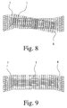
- Fig. 8
- eine numerische Simulation der Deformationen bei der Anregungs-Schwingung,
- Fig. 9
- eine numerische Simulation der Deformationen bei der Coriolis-Schwingung,
- Fig. 10
- ein fünftes Ausführungsbeispiel eines erfindungsgemäßen Massendurchflußmeßgerätes
- Fig. 11
- einen Schnitt durch das in Fig. 10 dargestellte Massendurchflußmeßgerät, längs der Linie XI - XI, und
- Fig. 12
- im Schnitt, ein sechstes, dem vierten Ausführungsbeispiel ähnliches Ausführungsbeispiel eines erfindungsgemäßen Massendurchflußmeßgerätes.
- Fig. 1
- a first embodiment of a mass flow meter according to the invention in section,
- Fig. 2
- a second embodiment of a mass flow meter according to the invention in section,
- Fig. 3
- a third embodiment of a mass flow meter according to the invention in section,
- 4 a) - c)
- a fourth embodiment of a mass flow meter according to the invention in section,
- Fig. 5
- a schematic diagram of the excitation vibration in the first embodiment of a mass flow meter according to the invention.
- 6 a), b)
- 2 shows a basic illustration of the movements of the pendulum in the first exemplary embodiment of a mass flow meter according to the invention,
- Fig. 7
- 1 shows a basic illustration of a Coriolis vibration of a Coriolis line of a mass flow measuring device according to the invention, which is excited by Coriolis forces,
- Fig. 8
- a numerical simulation of the deformations in the excitation oscillation,
- Fig. 9
- a numerical simulation of the deformations in the Coriolis vibration,
- Fig. 10
- a fifth embodiment of a mass flow meter according to the invention
- Fig. 11
- a section through the mass flow meter shown in Fig. 10, along the line XI - XI, and
- Fig. 12
- in section, a sixth, the fourth embodiment similar embodiment of a mass flow meter according to the invention.
Die in den Fig. 1 bis 4 und in den Fig. 10 bis 12 dargestellten Massendurchflußmeßgeräte
arbeiten, wie bekannt, nach dem Coriolis-Prinzip und bestehen in ihrem grundsätzlichen
Aufbau aus einer ein strömendes Medium führenden, geraden Coriolis-Leitung
1, aus einem der Coriolis-Leitung 1 zugeordneten, die Coriolis-Leitung 1 anregenden
Schwingungserzeuger 2 (Fig. 1 und 2) oder aber aus zwei der Coriolis-Leitung
1 zugeordneten, die Coriolis-Leitung 1 anregenden Schwingungserzeugern 2, 3
(Fig. 3 und 4 sowie 10 bis 12), aus zwei der Coriolis-Leitung 1 zugeordneten, Coriolis-Kräfte
und/oder auf Coriolis-Kräften beruhende Coriolis-Schwingungen erfassenden
Meßwertaufnehmern 4, 5 und aus einem die Coriolis-Leitung 1 aufnehmenden
Aufnahmezylinder 6.The mass flow meters shown in FIGS. 1 to 4 and in FIGS. 10 to 12
work, as is known, on the Coriolis principle and exist in their basic
Construction from a straight Coriolis line carrying a flowing
Erfindungsgemäß ist, wie dies die Fig. 1, 2, 3, 4, und 10 im einzelnen zeigen, die Coriolis-Leitung
1 über einen sich konisch erweiternden Einlaß 7 und einen sich ebenfalls
konisch erweiternden Auslaß 8 im Aufnahmezylinder 6 schwimmend gelagert. Durch
diese schwimmende Lagerung ist eine Deformation der Coriolis-Leitung 1, wie bei
den bekannten Massendurchflußmeßgeräten, von denen die Erfindung ausgeht, nicht
erforderlich; auch eine ''praktisch grenzenlos'' steife Coriolis-Leitung 1, die schwimmend
gelagert ist, läßt sich so anregen, daß in Verbindung mit einem in der Coriolis-Leitung
1 strömenden Medium Coriolis-Kräfte erzeugt werden.According to the invention, as shown in FIGS. 1, 2, 3, 4 and 10, the
Die Fig. 1, 2, und 3 sowie die Fig. 10 und 11 zeigen eine besonders bevorzugte Ausführungsform
des erfindungsgemäßen Massendurchflußmeßgerätes, die dadurch gekennzeichnet
ist, daß der Aufnahmezylinder 6 das Meßgerätgehäuse des Massendurchflußmeßgerätes
bildet, wobei der Aufnahmezylinder 6 als - relativ schwerer -
Metallblock mit Ausnehmungen zur Aufnahme von Coriolis-Leitung 1, Schwingungserzeuger
2 bzw. Schwingungserzeuger 2, 3 und Meßwertaufnehmer 4, 5 ausgebildet
ist. Diese Ausführungsform des erfindungsgemäßen Massendurchflußmeßgerätes
kann ohne weiteres zwischen den - nicht dargestellten - Flanschen angrenzender
Rohrleitungen eingeklemmt sein, wobei - natürlich in Grenzen - ein Nicht-Fluchten
der Coriolis-Leitung 1 mit den angrenzenden Rohrleitungen nicht zu Problemen
führt.1, 2, and 3 and FIGS. 10 and 11 show a particularly preferred embodiment
of the mass flow meter according to the invention, characterized in that
is that the receiving
Im Gegensatz zu dem, was die Fig. 1, 2 und 3 sowie den Fig. 10 und 11 zeigen, zeigen
die Fig. 4 und 12 ein Ausführungsbeispiel eines erfindungsgemäßen Massendurchflußmeßgerätes,
das dadurch gekennzeichnet ist, daß zusätzlich zu dem Aufnahmezylinder
6 noch ein Meßgerätgehäuse 9 vorhanden ist und zwischen der Coriolis-Leitung
1 und dem Meßgerätgehäuse 9 zwei Verbindungsleitungen 10, 11 vorgesehen
sind. Wie die Fig. 4 zeigt, sind die Verbindungsleitungen 10, 11 an den sich konisch
erweiternden Einlaß 7 und den sich ebenfalls konisch erweiternden Auslaß 8 - etwa
in der Mitte der Erweiterung - angeschlossen. Im übrigen sind die Verbindungsleitungen
10, 11 ebenso wie der Einlaß 7 und der Auslaß 8 als Membranen ausgebildet und
ist das Meßgerätgehäuse 9 mit Flanschen 12, 13 versehen. Contrary to what FIGS. 1, 2 and 3 and FIGS. 10 and 11
Im Unterschied zu der Fig. 4 zeigt die Fig. 12 ein Ausführungsbeispiel eines erfindungsgemäßen
Massendurchflußmeßgerätes, das dadurch gekennzeichnet ist, daß der
Einlaß 7 und der Auslaß 8 bogenförmig ausgeführt sind. Durch diese Ausführung
können sich der Einlaß 7 und der Auslaß 8 jeweils geringfügig ausdehnen, ohne das
große Spannungen in, Einlaß 7 oder im Auslaß 8 auftreten, so daß auch keine großen
Spannungen auf die Coriolis-Leitung 1 übertragen werden. Ebenso kann sich die Coriolis-Leitung
1 selber geringfügig ausdehnen, ohne das in ihr große Spannungen auftreten,
da der Einlaß 7 und der Auslaß 8 auch eine solche Ausdehnung - selbstverständlich
in geringem Maße - zulassen.In contrast to FIG. 4, FIG. 12 shows an embodiment of an inventive
Mass flow meter, which is characterized in that the
Fig. 4 a) zeigt das erfindungsgemäße Massendurchflußmeßgerät im statischen Zustand,
d.h. wenn keine Schwingungen vorhanden sind. Demgegenüber zeigt Fig. 4 b)
das erfindungsgemäße Massendurchflußmeßgerät bei einer vorhandenen Anregungs-Schwingung
und Fig. 4 c) das erfindungsgemäße Massendurchflußmeßgerät bei einer
vorhandenen Coriolis-Schwingung. Sowohl beim Vorliegen einer Anregungs-Schwingung
als auch beim Vorliegen einer Coriolis-Schwingung schwingt die Coriolis-Leitung
1 gegenphasig zum Aufnahmezylinder 6. Somit liegt ein ausbalanciertes
System vor, bei dem nur sehr wenig Energie und nur geringfügig Schwingungen auf
das Meßgerätgehäuse 9 übertragen wird.4 a) shows the mass flow meter according to the invention in the static state,
i.e. if there are no vibrations. In contrast, Fig. 4 b)
the mass flow meter according to the invention with an existing excitation vibration
and Fig. 4 c) the mass flow meter according to the invention at a
existing Coriolis vibration. Both when there is an excitation vibration
and also when there is a Coriolis vibration, the Coriolis line vibrates
1 in phase opposition to the receiving
In allen Ausführungsbeispielen nach den Fig. 1, 2 und 3 sowie den Fig. 10 und 11
schließen sich an die sich konisch erweiternden Ein- und Ausgänge 7,8 sich konisch
erweiternde Abschnitte 15, 16 des Aufnahmezylinders 6 an; das gilt nicht für das Ausführungsbeispiel
nach Fig. 4.In all the exemplary embodiments according to FIGS. 1, 2 and 3 and FIGS. 10 and 11
connect to the conically widening inputs and
Bei der Realisierung der Maßnahmen, die zu den erforderlichen Schwingungen der
Coriolis-Leitung 1 führen, ist bei den einzelnen Ausführungsbeispielen erfindungsgemäßer
Massendurchflußmeßgeräte natürlich berücksichtigt, daß die Coriolis-Leitung 1
im Aufnahmezylinder 6 schwimmend gelagert ist.When implementing the measures that lead to the required vibrations of the
Für die in den Fig. 1, 2, 3, 4 und 12 dargestellten Ausführungsbeispiele erfindungsgemäßer
Massendurchflußmeßgeräte gilt, daß der Schwingungserzeuger 2 (Fig. 1 und 2)
bzw. die Schwingungserzeuger 2, 3 (Fig. 3, 4 und 12) die Coriolis-Leitung 1 zu
Schwingungen um eine quer zur Längsachse der Coriolis-Leitung 1 verlaufende
Schwingungsachse anregt bzw. anregen, - wobei die Schwingungsachse in der senkrecht
zur Längsachse der Coriolis-Leitung 1 verlaufenden Mittelebene des Massendurchflußmeßgerätes
bzw. der Coriolis-Leitung 1 liegt. Die Coriolis-Leitung 1
schwingt also symmetrisch zur senkrecht zur Längsachse der Coriolis-Leitung 1 verlaufenden
Mittelebene, jedoch jeweils um 180° phasenverschoben.For the embodiments shown in FIGS. 1, 2, 3, 4 and 12 more inventive
Mass flow meters applies that the vibration generator 2 (Fig. 1 and 2)
or the
Die Fig. 1 zeigt ein Ausführungsbeispiel des erfindungsgemäßen Massendurchflußmeßgerätes,
bei dem der Schwingungserzeuger 2 zwischen dem Aufnahmezylinder 6
und einem quer zur Längsachse der Coriolis-Leitung 1, in Längsrichtung im wesentlichen
in der Mitte der Coriolis-Leitung 1 angebrachten Pendel 17 angreift. Zu dem
Pendel 17 gehören ein Pendelarm 18 und eine Kompensationsmasse 19. Die Kompensationsmasse
19 ist so gewählt, daß die Eigenfrequenz des Pendels 17 so weit als
möglich mit der Eigenfrequenz der Anregungs-Schwingung der Coriolis-Leitung 1
übereinstimmt.1 shows an embodiment of the mass flow meter according to the invention,
in which the
Bei dem in Fig. 2 dargestellten Ausführungsbeispiel eines erfindungsgemäßen Massendurchflußmeßgerätes
greift der Schwingungserzeuger 2 zwischen dem Aufnahmezylinder
6 und einem quer zur Längsachse der Coriolis-Leitung 1, in Längsrichtung
im wesentlichen in der Mitte der Coriolis-Leitung 1 angebrachten, mit einer Kompensationsmasse
20 versehenen Torsionsstab 21 an.In the embodiment of a mass flow meter according to the invention shown in Fig. 2
the
Für das in Fig. 3 dargestellte Ausführungsbeispiel eines erfindungsgemäßen Massendurchflußmeßgerätes
gilt, daß zwei Schwingungserzeuger 2, 3 in Längsrichtung der
Coriolis-Leitung 1, links und rechts der Mitte, angeordnet sind, wobei die Schwingungserzeuger
2, 3 als auf Federelementen 22, 23 abgestützte Piezoelemente 24, 25
ausgeführt sind.For the embodiment shown in Fig. 3 of a mass flow meter according to the invention
applies that two
Die Fig. 5 zeigt für das erste Ausführungsbeispiel eines erfindungsgemäßen Massendurchflußmeßgerätes
die Coriolis-Leitung 1 und das Pendel 17 in einer Prinzipdarstellung
für die Anregungs-Schwingung. Man erkennt ohne weiteres, daß die Coriolis-Leitung
1 Schwingungen um eine quer zur Längsachse der Coriolis-Leitung 1 verlaufende
Schwingungsachse ausführt. Die Schwingungsachse verläuft in Fig. 5 senkrecht
zur Zeichenebene. Aus der Fig. 5 kann man auch entnehmen, daß die Coriolis-Leitung
1 aufgrund der schwimmenden Lagerung vielmehr keine Deformation erfährt.
Deformiert werden praktisch nur die in Fig. 5 angedeuteten Membranen.Fig. 5 shows for the first embodiment of a mass flow meter according to the invention
the
In den Fig. 6 a) und 6 b) sind zur Erläuterung der an, Pendel 17 und an der Coriolis-Leitung
1 angreifenden Kräfte die Coriolis-Leitung 1 und das Pendel 17 in verschiedenen
Phasen der Anregungs-Schwingung dargestellt. Dabei sind die Deformationen
des Pendelarmes 18 jeweils stark vergrößert dargestellt.6 a) and 6 b) are to explain the
Die Fig. 7 zeigt nun prinzipiell die der in Fig. 5 dargestellten Anregungs-Schwingung
überlagerte Coriolis-Schwingung, die durch die beim Durchfluß des strömenden Mediums
durch die Coriolis-Leitung 1 entstehenden Coriolis-Kräfte angeregt wird. Die
Überlagerung der in Fig. 7 dargestellten Coriolis-Schwingung führt zu einer meßtechnisch
erfaßbaren Phasendifferenz der Schwingung zweier Punkte rechts und
links der Mitte der Coriolis-Leitung 1. Diese Phasendifferenz ist dem Massendurchfluß
proportional, da die die Phasendifferenz verursachenden Coriolis-Kräfte dem
Massendurchfluß durch die Coriolis-Leitung 1 proportional sind.Fig. 7 shows in principle that of the excitation vibration shown in Fig. 5
superimposed Coriolis vibration caused by the flow of the flowing medium
Coriolis forces generated by the
In den Fig. 8 und 9 sind die bei der Anregungs-Schwingung und die bei der Coriolis-Schwingung
auftretenden Deformationen der Coriolis-Leitung 1, des Einlasses 7 und
des Auslasses 8 dargestellt, ermittelt nach der Finite-Elemente-Methode. Man erkennt
ohne weteres, daß die Coriolis-Leitung 1 nahezu keine Deformation erfährt, während
der Einlaß 7 und der Auslaß 8 die aus der jeweiligen Schwingung resultierenden Deformationen
erfahren.8 and 9 are those in the excitation vibration and that in the Coriolis vibration
Deformations of the
Für das Ausführungsbeispiel eines erfindungsgemäßen Massendurchflußmeßgerätes.
das in den Fig. 10 und 11 dargestellt ist, gilt, daß die Schwingungserzeuger 2, 3 die
Enden der Coriolis-Leitung 1 zu taumelnden Bewegungen um die Längsachse der
Coriolis-Leitung 1 anregen, wobei die taumelnden Bewegungen der einen Hälfte der
Coriolis-Leitung 1 um 180° phasenverschoben gegenüber den taumelnden Bewegungen
der anderen Hälfte der Coriolis-Leitung 1 sind. Das ist im einzelnen dadurch
realisiert, daß als Schwingungserzeuger 2 bzw. 3 jeweils um 90° gegeneinander versetzte,
transversale Bewegungen generierende Schwingungserzeugerelemente 26
vorgesehen sind und die einzelnen Schwingungserzeugerelemente 26, um 90° phasenverschoben,
sinusförmig erregt werden. Hierbei handelt es sich also um das Generieren
einer rotatorischen Bewegung durch die Superposition von transversalen Bewegungen.For the embodiment of a mass flow meter according to the invention.
that is shown in FIGS. 10 and 11, applies that the
Claims (20)
Priority Applications (1)
| Application Number | Priority Date | Filing Date | Title |
|---|---|---|---|
| DK98117064T DK0908705T3 (en) | 1997-10-07 | 1998-09-09 | Mass Flow Measuring Device |
Applications Claiming Priority (8)
| Application Number | Priority Date | Filing Date | Title |
|---|---|---|---|
| DE19744303 | 1997-10-07 | ||
| DE19744303 | 1997-10-07 | ||
| DE19800225 | 1998-01-07 | ||
| DE19800225 | 1998-01-07 | ||
| DE19817453 | 1998-04-20 | ||
| DE19817453 | 1998-04-20 | ||
| DE19825775A DE19825775A1 (en) | 1997-10-07 | 1998-06-10 | Mass flow meter |
| DE19825775 | 1998-06-10 |
Publications (3)
| Publication Number | Publication Date |
|---|---|
| EP0908705A2 true EP0908705A2 (en) | 1999-04-14 |
| EP0908705A3 EP0908705A3 (en) | 1999-04-21 |
| EP0908705B1 EP0908705B1 (en) | 2004-06-16 |
Family
ID=27217806
Family Applications (1)
| Application Number | Title | Priority Date | Filing Date |
|---|---|---|---|
| EP98117064A Expired - Lifetime EP0908705B1 (en) | 1997-10-07 | 1998-09-09 | Mass flowmeter |
Country Status (5)
| Country | Link |
|---|---|
| US (2) | US6170339B1 (en) |
| EP (1) | EP0908705B1 (en) |
| JP (1) | JP3321104B2 (en) |
| DE (2) | DE19825775A1 (en) |
| DK (1) | DK0908705T3 (en) |
Cited By (5)
| Publication number | Priority date | Publication date | Assignee | Title |
|---|---|---|---|---|
| WO2000050854A1 (en) * | 1999-02-23 | 2000-08-31 | Micro Motion, Inc. | A low thermal stress case connect link for a straight tube coriolis flowmeter |
| WO2001002814A1 (en) * | 1999-06-30 | 2001-01-11 | Micro Motion, Inc. | Apparatus for connecting a coriolis flowmeter to a case |
| US6363794B1 (en) | 1999-08-13 | 2002-04-02 | Micro Motion, Inc. | Method and apparatus for Coriolis flowmeter having an accuracy enhancing balance bar |
| CN102401774A (en) * | 2010-08-24 | 2012-04-04 | 克洛纳有限公司 | Method for measuring viscosity of medium with coriolis volume flow measuring device |
| WO2020030472A1 (en) * | 2018-08-08 | 2020-02-13 | Endress+Hauser Flowtec Ag | Measuring sensor and measurement device |
Families Citing this family (18)
| Publication number | Priority date | Publication date | Assignee | Title |
|---|---|---|---|---|
| US6314820B1 (en) * | 1999-02-10 | 2001-11-13 | Micro Motion, Inc. | Lateral mode stabilizer for Coriolis flowmeter |
| DE19908072C2 (en) * | 1999-02-12 | 2002-10-17 | Krohne Ag Basel | The mass flow meter |
| US6466880B2 (en) | 2001-02-16 | 2002-10-15 | Micro Motion, Inc. | Mass flow measurement methods, apparatus, and computer program products using mode selective filtering |
| US6694279B2 (en) | 2001-02-16 | 2004-02-17 | Micro Motion, Inc. | Methods, apparatus, and computer program products for determining structural motion using mode selective filtering |
| US6535826B2 (en) | 2001-02-16 | 2003-03-18 | Micro Motion, Inc. | Mass flowmeter methods, apparatus, and computer program products using correlation-measure-based status determination |
| DE10159809B4 (en) * | 2001-12-05 | 2020-07-16 | Endress + Hauser Flowtec Ag | Vibration type sensor |
| JP4108081B2 (en) * | 2002-05-08 | 2008-06-25 | エンドレス ウント ハウザー フローテック アクチエンゲゼルシャフト | Vibration transducer |
| DE10351311B3 (en) * | 2003-10-31 | 2005-06-30 | Abb Patent Gmbh | Coriolis mass flowmeter |
| DE102004057088B3 (en) * | 2004-11-25 | 2006-06-01 | Krohne Ag | Coriolis mass flowmeter and method of making a measuring tube for a Coriolis mass flowmeter |
| US7690269B2 (en) * | 2005-06-01 | 2010-04-06 | Siemens Aktiengesellschaft | Coriolis flow meter having bearings for mounting the measuring tube in the region of the oscillation nodes |
| KR100691270B1 (en) * | 2005-08-05 | 2007-03-12 | 삼성전기주식회사 | Structure to automatically find and support nodal points of piezo stator |
| CA2650549C (en) * | 2006-05-01 | 2013-04-02 | Micro Motion, Inc. | A balancing structure for a single curved tube coriolis flow meter |
| JP5248047B2 (en) * | 2006-12-11 | 2013-07-31 | 株式会社アイチコーポレーション | Fall prevention device |
| WO2011031270A1 (en) | 2009-09-14 | 2011-03-17 | Micro Motion, Inc. | Corrosion-resistant coating for a vibratory flowmeter and method for forming the coating |
| US8511180B2 (en) | 2010-09-02 | 2013-08-20 | Ofer Melamed | Pressure difference flowmeter with flow barrier between a conduit and a reference tube |
| US9080908B2 (en) | 2013-07-24 | 2015-07-14 | Jesse Yoder | Flowmeter design for large diameter pipes |
| NL2016092B1 (en) * | 2016-01-14 | 2017-07-24 | Berkin Bv | Coriolis flowsensor. |
| DE102019134608A1 (en) * | 2019-12-16 | 2021-06-17 | Endress + Hauser Flowtec Ag | Sensor of a measuring device |
Family Cites Families (14)
| Publication number | Priority date | Publication date | Assignee | Title |
|---|---|---|---|---|
| US4217774A (en) * | 1979-01-04 | 1980-08-19 | Joram Agar | Apparatus for measuring the value of a fluid variable |
| DE3632800A1 (en) * | 1986-09-26 | 1988-04-07 | Flowtec Ag | MASS FLOW MEASURING DEVICE WORKING ACCORDING TO THE CORIOLIS PRINCIPLE |
| GB2212613B (en) * | 1987-11-19 | 1991-07-03 | Schlumberger Ind Ltd | Improvements in single vibrating tube transducers |
| JPH01296112A (en) * | 1988-05-24 | 1989-11-29 | Oval Eng Co Ltd | Coriolis mass flowmeter |
| DE3928839A1 (en) * | 1989-08-31 | 1991-03-07 | Hung Nguyen Dr Chi | METHOD AND DEVICE FOR MEASURING THE MASS FLOW RATE |
| EP0469448A1 (en) * | 1990-07-28 | 1992-02-05 | KROHNE MESSTECHNIK MASSAMETRON GmbH & Co. KG | Mass flow meter |
| US5373745A (en) * | 1991-02-05 | 1994-12-20 | Direct Measurement Corporation | Single path radial mode Coriolis mass flow rate meter |
| US5497665A (en) | 1991-02-05 | 1996-03-12 | Direct Measurement Corporation | Coriolis mass flow rate meter having adjustable pressure and density sensitivity |
| DE4124295A1 (en) * | 1991-07-22 | 1993-01-28 | Krohne Ag | MASS FLOW MEASURING DEVICE |
| US5323658A (en) * | 1992-06-19 | 1994-06-28 | Fuji Electric Co., Ltd. | Coriolis mass flowmeter |
| EP0578113B1 (en) * | 1992-07-06 | 1997-11-19 | Krohne Messtechnik Gmbh & Co. Kg | Mass flow measuring apparatus |
| US5691485A (en) * | 1994-06-06 | 1997-11-25 | Oval Corporation | Coaxial double tube type Coriolis flowmeter |
| DE19620079C2 (en) * | 1996-05-20 | 2001-08-23 | Krohne Messtechnik Kg | Mass flow meter |
| US5850039A (en) * | 1997-02-27 | 1998-12-15 | Micro Motion | Coriolis flowmeter having axially compliant case ends |
-
1998
- 1998-06-10 DE DE19825775A patent/DE19825775A1/en not_active Ceased
- 1998-09-09 DK DK98117064T patent/DK0908705T3/en active
- 1998-09-09 DE DE59811564T patent/DE59811564D1/en not_active Expired - Lifetime
- 1998-09-09 EP EP98117064A patent/EP0908705B1/en not_active Expired - Lifetime
- 1998-10-05 US US09/167,099 patent/US6170339B1/en not_active Expired - Fee Related
- 1998-10-06 JP JP28404198A patent/JP3321104B2/en not_active Expired - Fee Related
-
2000
- 2000-09-05 US US09/655,126 patent/US6301974B1/en not_active Expired - Fee Related
Cited By (10)
| Publication number | Priority date | Publication date | Assignee | Title |
|---|---|---|---|---|
| WO2000050854A1 (en) * | 1999-02-23 | 2000-08-31 | Micro Motion, Inc. | A low thermal stress case connect link for a straight tube coriolis flowmeter |
| CN100443862C (en) * | 1999-02-23 | 2008-12-17 | 微动公司 | Coriolis flow meter |
| WO2001002814A1 (en) * | 1999-06-30 | 2001-01-11 | Micro Motion, Inc. | Apparatus for connecting a coriolis flowmeter to a case |
| US6343517B1 (en) | 1999-06-30 | 2002-02-05 | Micro Motion, Inc. | Apparatus for connecting a coriolis flowmeter flow tube to a flowmeter case |
| US6718615B2 (en) | 1999-06-30 | 2004-04-13 | Micro Motion, Inc. | Method of forming a coriolis flowmeter |
| US6363794B1 (en) | 1999-08-13 | 2002-04-02 | Micro Motion, Inc. | Method and apparatus for Coriolis flowmeter having an accuracy enhancing balance bar |
| CN102401774A (en) * | 2010-08-24 | 2012-04-04 | 克洛纳有限公司 | Method for measuring viscosity of medium with coriolis volume flow measuring device |
| CN102401774B (en) * | 2010-08-24 | 2015-06-24 | 克洛纳有限公司 | Method for measuring viscosity of medium with coriolis volume flow measuring device |
| WO2020030472A1 (en) * | 2018-08-08 | 2020-02-13 | Endress+Hauser Flowtec Ag | Measuring sensor and measurement device |
| US11933806B2 (en) | 2018-08-08 | 2024-03-19 | Endress+Hauser Flowtec Ag | Measuring transducer and measurement device |
Also Published As
| Publication number | Publication date |
|---|---|
| DK0908705T3 (en) | 2004-10-25 |
| JPH11194045A (en) | 1999-07-21 |
| DE59811564D1 (en) | 2004-07-22 |
| JP3321104B2 (en) | 2002-09-03 |
| US6301974B1 (en) | 2001-10-16 |
| DE19825775A1 (en) | 1999-05-12 |
| EP0908705A3 (en) | 1999-04-21 |
| EP0908705B1 (en) | 2004-06-16 |
| US6170339B1 (en) | 2001-01-09 |
Similar Documents
| Publication | Publication Date | Title |
|---|---|---|
| EP0908705A2 (en) | Mass flowmeter | |
| DE4124295C2 (en) | ||
| DE19840782C2 (en) | Mass flow meter | |
| DE19621365A1 (en) | Mass flow meter | |
| EP1028310B1 (en) | Mass flowmeter | |
| EP2122311B1 (en) | Vibratory transducer | |
| EP2048480B1 (en) | Measuring sensor of vibration type | |
| EP0596178B1 (en) | Coriolis mass flow meter | |
| DE69838252T2 (en) | CORIOLIS FLOWMETER WITH WAVED FLOW TUBE | |
| EP2304393B1 (en) | Vibration-type transducer | |
| DE19710806C2 (en) | Mass flow meter | |
| WO2012150241A2 (en) | Vibration-type measuring sensor and measuring system formed therewith | |
| EP2516971A1 (en) | Vibration-type measuring sensor and measuring system formed therewith | |
| DE202021004560U1 (en) | Vibronial measuring system | |
| DE102009055069A1 (en) | Vibration-type measuring sensor for detecting e.g. mass flow rate of gas and for producing Coriolis forces in process measurement- and automation system, has tube arrangement exhibiting sectional plane running between measuring tubes | |
| EP1451534A1 (en) | Coriolis flowmeter comprising a straight tube | |
| EP1797404B1 (en) | Composite system, method for producing said system and sensor comprising a composite system of this type | |
| EP1685369B1 (en) | Vibratory-type measuring sensor | |
| WO2019129522A1 (en) | Vibratory measuring device having a measuring tube | |
| EP1914526B1 (en) | Measuring sensor of vibration type | |
| DE102010043708B4 (en) | Vibration type measuring transducer with at least two vibration systems and method for detecting a localized contamination carried in a medium flowing in a pipe | |
| DE102005042677A1 (en) | Coriolis mass flow sensor | |
| EP1949048B1 (en) | Vibration-type measuring transducer | |
| DE102005013649A1 (en) | Vibration type sensing unit e.g. Coriolis-mass flow rate-sensing unit, for use in e.g. industrial measuring and automation engineering, has compound system with two components connected with each other by welded joint |
Legal Events
| Date | Code | Title | Description |
|---|---|---|---|
| PUAI | Public reference made under article 153(3) epc to a published international application that has entered the european phase |
Free format text: ORIGINAL CODE: 0009012 |
|
| PUAL | Search report despatched |
Free format text: ORIGINAL CODE: 0009013 |
|
| AK | Designated contracting states |
Kind code of ref document: A2 Designated state(s): CH DE DK FR GB LI NL |
|
| AX | Request for extension of the european patent |
Free format text: AL;LT;LV;MK;RO;SI |
|
| AK | Designated contracting states |
Kind code of ref document: A3 Designated state(s): AT BE CH CY DE DK ES FI FR GB GR IE IT LI LU MC NL PT SE |
|
| AX | Request for extension of the european patent |
Free format text: AL;LT;LV;MK;RO;SI |
|
| 17P | Request for examination filed |
Effective date: 19991004 |
|
| AKX | Designation fees paid |
Free format text: AT BE CH CY DE DK LI |
|
| RBV | Designated contracting states (corrected) |
Designated state(s): CH DE DK FR GB LI NL |
|
| 17Q | First examination report despatched |
Effective date: 20010525 |
|
| GRAP | Despatch of communication of intention to grant a patent |
Free format text: ORIGINAL CODE: EPIDOSNIGR1 |
|
| GRAS | Grant fee paid |
Free format text: ORIGINAL CODE: EPIDOSNIGR3 |
|
| GRAA | (expected) grant |
Free format text: ORIGINAL CODE: 0009210 |
|
| AK | Designated contracting states |
Kind code of ref document: B1 Designated state(s): CH DE DK FR GB LI NL |
|
| REG | Reference to a national code |
Ref country code: GB Ref legal event code: FG4D Free format text: NOT ENGLISH |
|
| REG | Reference to a national code |
Ref country code: CH Ref legal event code: EP |
|
| REF | Corresponds to: |
Ref document number: 59811564 Country of ref document: DE Date of ref document: 20040722 Kind code of ref document: P |
|
| REG | Reference to a national code |
Ref country code: CH Ref legal event code: NV Representative=s name: KELLER & PARTNER PATENTANWAELTE AG |
|
| GBT | Gb: translation of ep patent filed (gb section 77(6)(a)/1977) |
Effective date: 20040720 |
|
| REG | Reference to a national code |
Ref country code: DK Ref legal event code: T3 |
|
| ET | Fr: translation filed | ||
| PLBE | No opposition filed within time limit |
Free format text: ORIGINAL CODE: 0009261 |
|
| STAA | Information on the status of an ep patent application or granted ep patent |
Free format text: STATUS: NO OPPOSITION FILED WITHIN TIME LIMIT |
|
| 26N | No opposition filed |
Effective date: 20050317 |
|
| PGFP | Annual fee paid to national office [announced via postgrant information from national office to epo] |
Ref country code: NL Payment date: 20050914 Year of fee payment: 8 |
|
| PG25 | Lapsed in a contracting state [announced via postgrant information from national office to epo] |
Ref country code: NL Free format text: LAPSE BECAUSE OF NON-PAYMENT OF DUE FEES Effective date: 20070401 |
|
| NLV4 | Nl: lapsed or anulled due to non-payment of the annual fee |
Effective date: 20070401 |
|
| PGFP | Annual fee paid to national office [announced via postgrant information from national office to epo] |
Ref country code: DE Payment date: 20101129 Year of fee payment: 13 |
|
| PGFP | Annual fee paid to national office [announced via postgrant information from national office to epo] |
Ref country code: CH Payment date: 20110923 Year of fee payment: 14 Ref country code: DK Payment date: 20110926 Year of fee payment: 14 |
|
| PGFP | Annual fee paid to national office [announced via postgrant information from national office to epo] |
Ref country code: FR Payment date: 20110928 Year of fee payment: 14 Ref country code: GB Payment date: 20110920 Year of fee payment: 14 |
|
| REG | Reference to a national code |
Ref country code: CH Ref legal event code: PL |
|
| GBPC | Gb: european patent ceased through non-payment of renewal fee |
Effective date: 20120909 |
|
| REG | Reference to a national code |
Ref country code: DK Ref legal event code: EBP |
|
| REG | Reference to a national code |
Ref country code: FR Ref legal event code: ST Effective date: 20130531 |
|
| PG25 | Lapsed in a contracting state [announced via postgrant information from national office to epo] |
Ref country code: LI Free format text: LAPSE BECAUSE OF NON-PAYMENT OF DUE FEES Effective date: 20120930 Ref country code: GB Free format text: LAPSE BECAUSE OF NON-PAYMENT OF DUE FEES Effective date: 20120909 Ref country code: CH Free format text: LAPSE BECAUSE OF NON-PAYMENT OF DUE FEES Effective date: 20120930 Ref country code: DE Free format text: LAPSE BECAUSE OF NON-PAYMENT OF DUE FEES Effective date: 20130403 |
|
| PG25 | Lapsed in a contracting state [announced via postgrant information from national office to epo] |
Ref country code: FR Free format text: LAPSE BECAUSE OF NON-PAYMENT OF DUE FEES Effective date: 20121001 |
|
| REG | Reference to a national code |
Ref country code: DE Ref legal event code: R119 Ref document number: 59811564 Country of ref document: DE Effective date: 20130403 |
|
| PG25 | Lapsed in a contracting state [announced via postgrant information from national office to epo] |
Ref country code: DK Free format text: LAPSE BECAUSE OF NON-PAYMENT OF DUE FEES Effective date: 20121001 |