EP0908600A2 - Formation testing apparatus - Google Patents
Formation testing apparatus Download PDFInfo
- Publication number
- EP0908600A2 EP0908600A2 EP98308218A EP98308218A EP0908600A2 EP 0908600 A2 EP0908600 A2 EP 0908600A2 EP 98308218 A EP98308218 A EP 98308218A EP 98308218 A EP98308218 A EP 98308218A EP 0908600 A2 EP0908600 A2 EP 0908600A2
- Authority
- EP
- European Patent Office
- Prior art keywords
- fluid
- formation
- pressure
- pressure sensor
- filter
- Prior art date
- Legal status (The legal status is an assumption and is not a legal conclusion. Google has not performed a legal analysis and makes no representation as to the accuracy of the status listed.)
- Withdrawn
Links
- 230000015572 biosynthetic process Effects 0.000 title claims abstract description 104
- 238000012360 testing method Methods 0.000 title claims abstract description 17
- 239000012530 fluid Substances 0.000 claims abstract description 181
- 238000004891 communication Methods 0.000 claims description 21
- 238000007789 sealing Methods 0.000 claims description 20
- 238000000034 method Methods 0.000 description 29
- 238000009530 blood pressure measurement Methods 0.000 description 8
- 230000003044 adaptive effect Effects 0.000 description 7
- 238000013528 artificial neural network Methods 0.000 description 7
- 238000001914 filtration Methods 0.000 description 6
- 230000008878 coupling Effects 0.000 description 5
- 238000010168 coupling process Methods 0.000 description 5
- 238000005859 coupling reaction Methods 0.000 description 5
- 238000005259 measurement Methods 0.000 description 5
- 230000005540 biological transmission Effects 0.000 description 4
- 238000010586 diagram Methods 0.000 description 4
- 230000002708 enhancing effect Effects 0.000 description 2
- 238000007792 addition Methods 0.000 description 1
- 238000012217 deletion Methods 0.000 description 1
- 230000037430 deletion Effects 0.000 description 1
- 238000013461 design Methods 0.000 description 1
- 238000001514 detection method Methods 0.000 description 1
- 238000005553 drilling Methods 0.000 description 1
- 230000000694 effects Effects 0.000 description 1
- 238000011156 evaluation Methods 0.000 description 1
- 238000004519 manufacturing process Methods 0.000 description 1
- 238000012986 modification Methods 0.000 description 1
- 230000004048 modification Effects 0.000 description 1
- 238000005070 sampling Methods 0.000 description 1
- 238000006467 substitution reaction Methods 0.000 description 1
Images

Classifications
-
- E—FIXED CONSTRUCTIONS
- E21—EARTH OR ROCK DRILLING; MINING
- E21B—EARTH OR ROCK DRILLING; OBTAINING OIL, GAS, WATER, SOLUBLE OR MELTABLE MATERIALS OR A SLURRY OF MINERALS FROM WELLS
- E21B49/00—Testing the nature of borehole walls; Formation testing; Methods or apparatus for obtaining samples of soil or well fluids, specially adapted to earth drilling or wells
- E21B49/08—Obtaining fluid samples or testing fluids, in boreholes or wells
- E21B49/087—Well testing, e.g. testing for reservoir productivity or formation parameters
- E21B49/088—Well testing, e.g. testing for reservoir productivity or formation parameters combined with sampling
-
- E—FIXED CONSTRUCTIONS
- E21—EARTH OR ROCK DRILLING; MINING
- E21B—EARTH OR ROCK DRILLING; OBTAINING OIL, GAS, WATER, SOLUBLE OR MELTABLE MATERIALS OR A SLURRY OF MINERALS FROM WELLS
- E21B33/00—Sealing or packing boreholes or wells
- E21B33/10—Sealing or packing boreholes or wells in the borehole
- E21B33/12—Packers; Plugs
- E21B33/124—Units with longitudinally-spaced plugs for isolating the intermediate space
- E21B33/1243—Units with longitudinally-spaced plugs for isolating the intermediate space with inflatable sleeves
-
- E—FIXED CONSTRUCTIONS
- E21—EARTH OR ROCK DRILLING; MINING
- E21B—EARTH OR ROCK DRILLING; OBTAINING OIL, GAS, WATER, SOLUBLE OR MELTABLE MATERIALS OR A SLURRY OF MINERALS FROM WELLS
- E21B47/00—Survey of boreholes or wells
- E21B47/06—Measuring temperature or pressure
-
- E—FIXED CONSTRUCTIONS
- E21—EARTH OR ROCK DRILLING; MINING
- E21B—EARTH OR ROCK DRILLING; OBTAINING OIL, GAS, WATER, SOLUBLE OR MELTABLE MATERIALS OR A SLURRY OF MINERALS FROM WELLS
- E21B47/00—Survey of boreholes or wells
- E21B47/12—Means for transmitting measuring-signals or control signals from the well to the surface, or from the surface to the well, e.g. for logging while drilling
- E21B47/14—Means for transmitting measuring-signals or control signals from the well to the surface, or from the surface to the well, e.g. for logging while drilling using acoustic waves
- E21B47/18—Means for transmitting measuring-signals or control signals from the well to the surface, or from the surface to the well, e.g. for logging while drilling using acoustic waves through the well fluid, e.g. mud pressure pulse telemetry
-
- E—FIXED CONSTRUCTIONS
- E21—EARTH OR ROCK DRILLING; MINING
- E21B—EARTH OR ROCK DRILLING; OBTAINING OIL, GAS, WATER, SOLUBLE OR MELTABLE MATERIALS OR A SLURRY OF MINERALS FROM WELLS
- E21B49/00—Testing the nature of borehole walls; Formation testing; Methods or apparatus for obtaining samples of soil or well fluids, specially adapted to earth drilling or wells
- E21B49/08—Obtaining fluid samples or testing fluids, in boreholes or wells
- E21B49/10—Obtaining fluid samples or testing fluids, in boreholes or wells using side-wall fluid samplers or testers
Definitions
- the present invention relates generally to operations and equipment for use in a subterranean well and, in an embodiment described herein, more particularly provides formation testing apparatus and methods of testing a formation. More particularly the present invention relates to formation testing apparatus, and associated methods, having noise reduction capability.
- fluid pressure pulses In operations performed in a subterranean well, it is quite common for data to be transmitted via fluid pressure pulses in the wellbore. This type of data transmission is typically referred to as "mud pulse telemetry".
- fluid is circulated from the earth's surface to a downhole tool which periodically restricts, or otherwise changes, the rate of flow of the circulating fluid therethrough, thereby creating variations in the pressure of the circulating fluid.
- the pressure pulses (the frequency of which are typically on the order of about 1 Hz) are then detected at the earth's surface and the data decoded therefrom.
- fluid pressure pulses may interfere with other operations in the well. For example, it is known that fluid pressure pulses may enter into a formation intersected by the wellbore and change the pressure of the fluid within the formation. This can result in inaccurate measurements of the formation fluid pressure taken by a formation testing tool.
- fluid is drawn into the tool from the formation.
- the pressure of the fluid is measured both before, during, and after it is drawn into the tool. These measurements are then utilized to calculate characteristics of the formation and predict its future productivity. Inaccuracies in these measurements may frustrate attempts to characterize the formation, leading to loss of production from the formation or loss of resources expended in producing the formation.
- apparatus which is a formation testing tool.
- the tool is capable of taking accurate measurements of formation fluid pressure, even though the formation fluid pressure may be influenced by pressure pulses in the wellbore. Associated methods are also provided.
- apparatus which includes a pressure sensor coupled to an appropriately configured filter.
- the pressure sensor may be placed in fluid communication with a formation intersected by the well.
- An output of the pressure sensor may include combined indications of the formation fluid pressure and pressure pulses corresponding to the pressure pulses in the wellbore.
- the filter removes the pressure pulse indications from the pressure sensor output.
- the filter may be constructed to pass the formation fluid pressure frequencies while filtering out the pressure pulse frequencies. For example, if it is known that the formation fluid pressure frequency is less than the pressure pulse frequency, the filter may be provided as a low pass filter.
- filters may be utilized as well.
- another pressure sensor may be provided and placed in fluid communication with the wellbore or other location in which the pressure pulses are transmitted.
- the output of this pressure sensor may then be coupled to the filter, so that the filter is capable of determining the contribution of the pressure pulses to the output of the formation fluid pressure sensor.
- the filter may then operate to remove this pressure pulse contribution from the formation fluid pressure sensor output.
- filters usable in the apparatus and having these capabilities are adaptive filters and neural network filters, which are well known to those of ordinary skill in the signal filtering art.
- a formation testing apparatus for use within a wellbore, comprising a first fluid passage for receiving fluid therein from a formation intersecting the wellbore; a first fluid pressure sensor interconnected to the first fluid passage; and a filter coupled to the first pressure sensor.
- the apparatus can be used within a wellbore of the type in which fluid pressure pulses having a first frequency are communicated with the formation.
- the apparatus can be used in a wellbore of the type in which the formation fluid pressure is influenced in part by pressure pulses in the wellbore.
- the apparatus may further comprise a sealing device configured for sealingly engaging at least a portion of the formation, the sealing device being disposed relative to the first fluid passage such that the first fluid passage is in fluid communication with the formation when the sealing device sealingly engages the formation.
- the apparatus further comprises: a second fluid passage for receiving fluid therein from the wellbore; and a second fluid pressure sensor interconnected to the second fluid passage, the second pressure sensor being capable of sensing the fluid pressure pulses, and an output of the second pressure sensor being coupled to the filter.
- the filter is preferably an adaptive filter or a neural network filter, rather than a low pass filter.
- a fluid testing apparatus for use within a wellbore wherein fluid pressure pulses having a first frequency are communicated with a formation intersected by the wellbore, comprising: a first fluid passage for receiving fluid therein from the formation; a first fluid pressure sensor interconnected to the first fluid passage, the sensor being capable of sensing a combination of the fluid pressure pulses and the pressure of the fluid received from the formation, and the first pressure sensor producing an output; and a filter coupled to the first pressure sensor, the filter being capable of removing indications of the fluid pressure pulses from the first pressure sensor output.
- the filter is a low pass filter configured to remove the first frequency from the first pressure sensor output.
- a second fluid pressure frequency is imparted to the fluid received into the first fluid passage due to receiving the fluid into the first fluid passage, and the filter passes the second frequency but removes the first frequency from the first pressure sensor output.
- the second frequency may be less than the first frequency.
- the low pass filter may be configured to pass frequencies less than a third frequency between the first and second frequencies.
- the low pass filter may be configured to pass frequencies up to and including the second frequency.
- the apparatus further comprises: a second fluid passage for receiving fluid therein from the wellbore; and a second fluid pressure sensor interconnected to the second fluid passage, the second pressure sensor being capable of sensing the fluid pressure pulses, and an output of the second pressure sensor being coupled to the filter.
- the filter may be an adaptive filter capable of removing indications of the fluid pressure pulses from the first pressure sensor output based on the second fluid pressure sensor output.
- the filter may be a neural network filter capable of removing indications of the fluid pressure pulses from the first pressure sensor output based on the second fluid pressure sensor output.
- formation testing apparatus for sensing the pressure of fluid received into the apparatus from a formation intersected by a wellbore, the formation fluid pressure being influenced in part by pressure pulses in the wellbore
- the apparatus comprising: a sealing device configured for sealingly engaging at least a portion of the formation; a first fluid passage disposed relative to the sealing device such that the first fluid passage is in fluid communication with the formation when the sealing device sealingly engages the formation; a first fluid pressure sensor in fluid communication with the first fluid passage; and a filter coupled to the first fluid pressure sensor.
- the filter may be a low pass filter.
- the sealing device is configured to substantially isolate the portion of the formation from a portion of the wellbore when the sealing device sealingly engages the formation.
- the apparatus further comprises a second fluid passage disposed relative to the sealing device such that the second fluid passage is in fluid communication with the portion of the wellbore and is capable of receiving the pressure pulses therein.
- the apparatus may further comprise a second fluid pressure sensor in fluid communication with the second fluid passage.
- the second pressure sensor may be coupled to the filter.
- the filter may be an adaptive filter or a neural network filter.
- a method of measuring the pressure of fluid received in a testing apparatus from a formation intersected by a wellbore in the presence of fluid pressure pulses transmitted to the formation comprising the steps of: interconnecting a first fluid pressure sensor to a first fluid passage in fluid communication with the formation; producing an output of the first pressure sensor including indications of the formation fluid pressure and the pressure pulses; coupling the first pressure sensor output to a filter; and filtering out the indications of the pressure pulses from the first pressure sensor output.
- the filter may be a low pass filter.
- the filtering step may be performed by passing indications in the first pressure sensor output which have frequencies less than a predetermined frequency, and removing indications in the first pressure sensor output which have frequencies greater than the predetermined frequency.
- the method may further comprise the steps of: interconnecting a second fluid pressure sensor to a second fluid passage in fluid communication with the wellbore; producing an output of the second pressure sensor including an indication of the pressure pulses; and coupling the second pressure sensor to the filter.
- the filtering step may further comprise adapting the filter to the indication of the pressure pulses output by the second pressure sensor.
- the filter may be an adaptive filter or a neural network filter.
- a method of removing extraneous fluid pressure indications from an output of a first pressure sensor in fluid communication with a formation intersected by a wellbore comprising the steps of: coupling the first pressure sensor output to a filter; and permitting indications in the first pressure sensor output other than the extraneous fluid pressure indications to pass through the filter.
- the filter may be a low pass filter.
- the method may further comprise the steps of: coupling a second pressure sensor output to the filter.
- the second pressure sensor output may include indications of the extraneous fluid pressure.
- the filter may be an adaptive filter or a neural network.
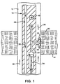
- FIG 1 Representatively illustrated in FIG 1 is a formation testing tool 10 which embodies principles of the present invention.
- directional terms such as “above”, “below”, “upper”, “lower”, etc., are used for convenience in referring to the accompanying drawings. Additionally, it is to be understood that the various embodiments of the present invention described herein may be utilized in various orientations, such as inclined, inverted, horizontal, vertical, etc., without departing from the principles of the present invention.
- the tool 10 is shown disposed within a wellbore 12 of a well.
- the wellbore 12 intersects a formation, or interval of a formation, 14 from which it is desired to obtain fluid pressure measurements.
- the tool 10 is of the well known type which has a laterally outwardly extendable fluid sampling portion 16 including a sealing device 18 for contacting and sealingly engaging the formation 14. In this manner, a portion 20 of the formation 14 is substantially isolated from the remainder of the wellbore 12 external to the sealing device 18.
- a fluid passage 22 extends into the interior of the tool 10 and is in fluid communication with the formation portion 20.
- a piston 24 When a piston 24 is stroked downwardly as viewed in FIG. 1, fluid is drawn into the fluid passage 22 from the formation 14.
- the pressure of the formation fluid is sensed by a fluid pressure sensor 26, which is in fluid communication with the fluid passage 22.
- An axial fluid conduit 28 is formed through the tool 10. Via a tubular string (not shown) attached to the tool 10 and extending to the earth's surface, the fluid conduit 28 is utilized to permit circulation of fluid (indicated by arrows 30), such as drilling mud, downwardly through the tool 10 and then axially upward back to the earth's surface through the wellbore 12.
- fluid indicated by arrows 30
- Other equipment such as conventional mud motors, mud pulse telemetry tools, tubular strings, etc. (not shown) may be connected to the tool 10 and extend downwardly therefrom.
- a mud pulse telemetry tool may be utilized to generate data-carrying pressure pulses in the circulating fluid, so that the pressure pulses may be received at the earth's surface and decoded.
- pressure pulses may be present in the fluid 30 due to other causes, may be present whether or not the fluid is simultaneously being circulated through the well, and the fluid may be circulated in a reverse direction or not circulated at all.
- other pressure pulse sources and other dispositions of the fluid 30 may be utilized without departing from the principles of the present invention.
- the fluid 30 contacts the formation 14, even though it may be substantially isolated from the formation portion 20 by the sealing device 18. It will be readily appreciated by one of ordinary skill in the art that pressure pulses in the fluid 30 may be transmitted into the formation 14 via those areas of the formation intersected by the wellbore 12 and external to the sealing device 18. It will also be appreciated that the pressure pulses may be transmitted through the formation 14 to the portion 20 and influence the pressure of the formation fluid drawn into the fluid passage 22. Thus, the pressure sensor 26 may produce an output which indicates a combination of the formation fluid pressure and the pressure pulses transmitted into and through the formation 14 to the portion 20.
- the tool 10 includes features which remove the indications of the pressure pulses from the pressure sensor 26 output, thereby enhancing the accuracy of the formation fluid pressure measurements obtained by the tool.
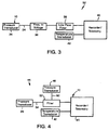
- One method 32 of accomplishing this objective is representatively illustrated in block diagram form in FIG. 3.
- the pressure sensor 26 is shown as a pressure transducer whose output 34 is coupled via a frequency to voltage converter 36 to a low pass filter 38.
- the frequency to voltage converter 36 is preferred where the pressure sensor 26 is of the type which has a frequency output 34. However, where a sensor 26 having a voltage output is used, the converter 36 is not needed. Additionally, it is to be clearly understood that it is not necessary for the pressure sensor output 34 to be voltage modulated, or for the output to be converted from frequency to voltage modulated, in accordance with the principles of the present invention.
- the filter 38 is preferably a low pass filter as shown in FIG. 3. It is believed that, in most circumstances. the frequency of the pressure pulses transmitted from the fluid 30, through the formation 14 and to the portion 20 will be substantially greater than the frequency of the formation fluid pressure which would be sensed in the absence of the pressure pulses.
- the frequency of the pressure pulses may be about 1 Hz
- the formation fluid pressure may be about 0.5 Hz (due to drawdown of fluid from the formation 14 into the tool 10, and subsequent fluid pressure buildup, etc.)
- the filter 38 may be configured to pass the formation fluid pressure frequencies but block passage of the pressure pulse frequencies.
- the filter 38 could be configured to pass frequencies less than about 0.75 Hz, but block frequencies above about 0.75 Hz.
- the filter 38 may be configured to pass frequencies equal to or less than the formation fluid pressure frequency.
- other types of filters may be used for the filter 38, and other configurations of the filter may be utilized, without departing from the principles of the present invention.
- the pressure sensor output 34 is connected to a conventional recorder and/or telemetry module 40.
- the output 34 may be recorded in the tool 10 for later retrieval, or transmitted directly to the earth's surface, for example, via mud pulse telemetry, other acoustic telemetry, electromagnetic waves, wireline connected to the tool 10, etc.
- Other sensors and types of sensors may be connected to the recorder/telemetry module 40 as well.
- a temperature sensor 42 may be included in the tool 10 for measuring the temperature of the formation fluid or of the wellbore 12 at the formation 14.
- FIG. 4 Another method 44 of enhancing the accuracy of the formation fluid pressure measurements taken by the tool 10 is representatively depicted in block diagram form in FIG. 4.
- the method 44 utilizes an additional pressure sensor 46 to detect the pressure pulses in the wellbore 12.
- the sensor 46 may be seen included in the tool 10 and in fluid communication with a fluid passage 48 which, in turn, is in fluid communication with the wellbore 12.
- the additional sensor 46 and fluid passage 48 are not needed in the tool 10.
- the output 34 of the sensor 26 (which includes indications of both the pressure pulses and of the formation fluid pressure) and an output 50 of the sensor 46 (which includes an indication of the pressure pulses in the fluid 30) are coupled to a filter 52.
- the filter 52 is of the type that removes extraneous signals (also termed "noise") based at least in part on a separate detection of the extraneous signals.
- This type of filter is well known to a person of ordinary skill in the signal filtering art and examples thereof may be found in a publication entitled Neural Network Design by M.T. Hagan et al., published in 1996 by PWS Publishing Co., Boston, Mass., the disclosure of which is incorporated herein by this reference.
- Another example of a type of filter which may be used for the filter 52 is an adaptive filter, also well known to a person of ordinary skill in the art.
- FIG. 2 another formation testing tool 54 embodying principles of the present invention is schematically and representatively illustrated. Elements shown in FIG. 2 which are similar to those previously described are indicated in FIG. 2 using the same reference number, with an added suffix "a".
- the tool 54 is of the type having an upper portion 56 axially reciprocably disposed relative to a lower portion 58.
- the lower portion 58 is positioned opposite the formation 14a and a pair of axially spaced apart inflatable packer elements 60 are inflated, so that they radially outwardly extend into sealing engagement with the formation 14a. In this manner, a portion 62 of the formation 14a is substantially isolated from the remainder of the wellbore 12a.
- An example of this type of tool is the RT031 and RT032 available from Halliburton Energy Services.
- portion 62 differs from the previously described portion 20 in that the portion 62 extends circumferentially about the tool 54 and the packer elements 60 effectively isolate an upper portion 64 of the wellbore 12a from a lower portion 66 of the wellbore.
- the fluid passage 22a is in fluid communication with the formation portion 62, and so. when the upper tool portion 56 is axially upwardly displaced relative to the lower portion 58, fluid from the formation 14a is drawn into the fluid passage 22a, and its pressure is measured by the pressure sensor 26a.
- the pressure pulses in the wellbore 12a may be caused by mud pulse telemetry or may originate at another source. If mud pulse telemetry is utilized, the fluid 30a may be circulated from the earth's surface. downwardly through a tubular string (not shown) attached above the tool 54, outwardly through a radially extending fluid passage 68 to the upper wellbore portion 64, and upwardly to the earth's surface. Thus, the pressure pulses may be present in the upper wellbore portion 64, but not in the lower wellbore portion 66. Nevertheless, the pressure pulses may still be communicated through the formation 14a to the portion 62.
- the additional pressure sensor 46a may be installed in the tool 54 with the fluid passage 48a providing fluid communication between the wellbore 12a and the pressure sensor 46a.
- the fluid passage 48a should be in fluid communication with the upper wellbore portion, but it may additionally be placed in fluid communication with the lower wellbore portion 66 if desired.
- the tool 54 demonstrates that the methods 32, 44 may be utilized with a variety of tools, that it is not necessary for the pressure pulses to be present in the entire wellbore, and that other manners of sealingly engaging and drawing fluid from the formation 14a may be utilized, without departing from the principles of the present invention.
Landscapes
- Engineering & Computer Science (AREA)
- Life Sciences & Earth Sciences (AREA)
- Mining & Mineral Resources (AREA)
- Geology (AREA)
- Physics & Mathematics (AREA)
- Environmental & Geological Engineering (AREA)
- Fluid Mechanics (AREA)
- General Life Sciences & Earth Sciences (AREA)
- Geochemistry & Mineralogy (AREA)
- Geophysics (AREA)
- Remote Sensing (AREA)
- Acoustics & Sound (AREA)
- Measuring Fluid Pressure (AREA)
Abstract

Description
- The present invention relates generally to operations and equipment for use in a subterranean well and, in an embodiment described herein, more particularly provides formation testing apparatus and methods of testing a formation. More particularly the present invention relates to formation testing apparatus, and associated methods, having noise reduction capability.
- In operations performed in a subterranean well, it is quite common for data to be transmitted via fluid pressure pulses in the wellbore. This type of data transmission is typically referred to as "mud pulse telemetry". In a well known method of producing the fluid pressure pulses, fluid is circulated from the earth's surface to a downhole tool which periodically restricts, or otherwise changes, the rate of flow of the circulating fluid therethrough, thereby creating variations in the pressure of the circulating fluid. The pressure pulses (the frequency of which are typically on the order of about 1 Hz) are then detected at the earth's surface and the data decoded therefrom.
- Unfortunately, such fluid pressure pulses may interfere with other operations in the well. For example, it is known that fluid pressure pulses may enter into a formation intersected by the wellbore and change the pressure of the fluid within the formation. This can result in inaccurate measurements of the formation fluid pressure taken by a formation testing tool.
- In one type of formation testing tool, fluid is drawn into the tool from the formation. The pressure of the fluid is measured both before, during, and after it is drawn into the tool. These measurements are then utilized to calculate characteristics of the formation and predict its future productivity. Inaccuracies in these measurements may frustrate attempts to characterize the formation, leading to loss of production from the formation or loss of resources expended in producing the formation.
- Since the accuracy of formation fluid pressure measurements is directly related to the economics of producing a well, it is generally considered prudent to ensure the highest possible accuracy of these measurements. Thus, it is typically not recommended to take formation fluid pressure measurements while simultaneously utilizing pressure pulse data transmission in the wellbore. As a result, this very useful form of data transmission is not available to transmit the formation fluid pressure measurements to the earth's surface for evaluation.
- From the foregoing, it can be seen that it would be quite desirable to provide apparatus and methods which permit utilization of pressure pulse data transmission while simultaneously taking formation fluid pressure measurements. Additionally, apparatus and methods for eliminating the effects of extraneous fluid pressure pulses on formation fluid pressure measurements would be desirable as well. It is accordingly an object of the present invention to provide such apparatus and methods.
- In carrying out the principles of the present invention, in accordance with an embodiment thereof, apparatus is provided which is a formation testing tool. The tool is capable of taking accurate measurements of formation fluid pressure, even though the formation fluid pressure may be influenced by pressure pulses in the wellbore. Associated methods are also provided.
- In broad terms, apparatus is provided which includes a pressure sensor coupled to an appropriately configured filter. The pressure sensor may be placed in fluid communication with a formation intersected by the well. An output of the pressure sensor may include combined indications of the formation fluid pressure and pressure pulses corresponding to the pressure pulses in the wellbore. The filter removes the pressure pulse indications from the pressure sensor output.
- Where it is known that the pressure pulses have a frequency or frequencies different from a frequency or frequencies of the formation fluid pressure, the filter may be constructed to pass the formation fluid pressure frequencies while filtering out the pressure pulse frequencies. For example, if it is known that the formation fluid pressure frequency is less than the pressure pulse frequency, the filter may be provided as a low pass filter.
- Other, more sophisticated filters may be utilized as well. For example, another pressure sensor may be provided and placed in fluid communication with the wellbore or other location in which the pressure pulses are transmitted. The output of this pressure sensor may then be coupled to the filter, so that the filter is capable of determining the contribution of the pressure pulses to the output of the formation fluid pressure sensor. The filter may then operate to remove this pressure pulse contribution from the formation fluid pressure sensor output. Examples of filters usable in the apparatus and having these capabilities are adaptive filters and neural network filters, which are well known to those of ordinary skill in the signal filtering art.
- According to another aspect of the invention there is provided a formation testing apparatus for use within a wellbore, comprising a first fluid passage for receiving fluid therein from a formation intersecting the wellbore; a first fluid pressure sensor interconnected to the first fluid passage; and a filter coupled to the first pressure sensor.
- The apparatus can be used within a wellbore of the type in which fluid pressure pulses having a first frequency are communicated with the formation. The apparatus can be used in a wellbore of the type in which the formation fluid pressure is influenced in part by pressure pulses in the wellbore.
- The apparatus may further comprise a sealing device configured for sealingly engaging at least a portion of the formation, the sealing device being disposed relative to the first fluid passage such that the first fluid passage is in fluid communication with the formation when the sealing device sealingly engages the formation.
- In an embodiment the apparatus further comprises: a second fluid passage for receiving fluid therein from the wellbore; and a second fluid pressure sensor interconnected to the second fluid passage, the second pressure sensor being capable of sensing the fluid pressure pulses, and an output of the second pressure sensor being coupled to the filter. In this embodiment, the filter is preferably an adaptive filter or a neural network filter, rather than a low pass filter.
- According to another aspect of the invention there is provided a fluid testing apparatus for use within a wellbore wherein fluid pressure pulses having a first frequency are communicated with a formation intersected by the wellbore, comprising: a first fluid passage for receiving fluid therein from the formation; a first fluid pressure sensor interconnected to the first fluid passage, the sensor being capable of sensing a combination of the fluid pressure pulses and the pressure of the fluid received from the formation, and the first pressure sensor producing an output; and a filter coupled to the first pressure sensor, the filter being capable of removing indications of the fluid pressure pulses from the first pressure sensor output.
- In an embodiment, the filter is a low pass filter configured to remove the first frequency from the first pressure sensor output.
- In an embodiment, a second fluid pressure frequency is imparted to the fluid received into the first fluid passage due to receiving the fluid into the first fluid passage, and the filter passes the second frequency but removes the first frequency from the first pressure sensor output. The second frequency may be less than the first frequency.
- The low pass filter may be configured to pass frequencies less than a third frequency between the first and second frequencies. The low pass filter may be configured to pass frequencies up to and including the second frequency.
- In an embodiment, the apparatus further comprises: a second fluid passage for receiving fluid therein from the wellbore; and a second fluid pressure sensor interconnected to the second fluid passage, the second pressure sensor being capable of sensing the fluid pressure pulses, and an output of the second pressure sensor being coupled to the filter.
- The filter may be an adaptive filter capable of removing indications of the fluid pressure pulses from the first pressure sensor output based on the second fluid pressure sensor output.
- The filter may be a neural network filter capable of removing indications of the fluid pressure pulses from the first pressure sensor output based on the second fluid pressure sensor output.
- According to another aspect of the invention there is provided formation testing apparatus for sensing the pressure of fluid received into the apparatus from a formation intersected by a wellbore, the formation fluid pressure being influenced in part by pressure pulses in the wellbore, the apparatus comprising: a sealing device configured for sealingly engaging at least a portion of the formation; a first fluid passage disposed relative to the sealing device such that the first fluid passage is in fluid communication with the formation when the sealing device sealingly engages the formation; a first fluid pressure sensor in fluid communication with the first fluid passage; and a filter coupled to the first fluid pressure sensor. The filter may be a low pass filter.
- In an embodiment, the sealing device is configured to substantially isolate the portion of the formation from a portion of the wellbore when the sealing device sealingly engages the formation. In an embodiment, the apparatus further comprises a second fluid passage disposed relative to the sealing device such that the second fluid passage is in fluid communication with the portion of the wellbore and is capable of receiving the pressure pulses therein. The apparatus may further comprise a second fluid pressure sensor in fluid communication with the second fluid passage. The second pressure sensor may be coupled to the filter. The filter may be an adaptive filter or a neural network filter.
- According to another aspect of the invention there is provided a method of measuring the pressure of fluid received in a testing apparatus from a formation intersected by a wellbore in the presence of fluid pressure pulses transmitted to the formation. the method comprising the steps of: interconnecting a first fluid pressure sensor to a first fluid passage in fluid communication with the formation; producing an output of the first pressure sensor including indications of the formation fluid pressure and the pressure pulses; coupling the first pressure sensor output to a filter; and filtering out the indications of the pressure pulses from the first pressure sensor output. The filter may be a low pass filter.
- The filtering step may be performed by passing indications in the first pressure sensor output which have frequencies less than a predetermined frequency, and removing indications in the first pressure sensor output which have frequencies greater than the predetermined frequency.
- The method may further comprise the steps of: interconnecting a second fluid pressure sensor to a second fluid passage in fluid communication with the wellbore; producing an output of the second pressure sensor including an indication of the pressure pulses; and coupling the second pressure sensor to the filter. The filtering step may further comprise adapting the filter to the indication of the pressure pulses output by the second pressure sensor. The filter may be an adaptive filter or a neural network filter.
- According to another aspect of the invention there is provided a method of removing extraneous fluid pressure indications from an output of a first pressure sensor in fluid communication with a formation intersected by a wellbore, the method comprising the steps of: coupling the first pressure sensor output to a filter; and permitting indications in the first pressure sensor output other than the extraneous fluid pressure indications to pass through the filter. The filter may be a low pass filter.
- The method may further comprise the steps of: coupling a second pressure sensor output to the filter. In the second pressure sensor output coupling step, the second pressure sensor output may include indications of the extraneous fluid pressure. The filter may be an adaptive filter or a neural network.
- Reference is now made to the accompanying drawings, in which:
- FIG. 1 is a schematicized cross-sectional view of a first embodiment of a formation testing tool according to the present invention;
- FIG. 2 is a schematicized cross-sectional view of a second embodiment of a formation testing tool according to the present invention;
- FIG. 3 is a block diagram of a first embodiment of a method according to the present invention; and
- FIG. 4 is a block diagram of a second embodiment of a method according to the present invention.
-
- Representatively illustrated in FIG 1 is a
formation testing tool 10 which embodies principles of the present invention. In the following description of thetool 10 and other apparatus and methods described herein, directional terms, such as "above", "below", "upper", "lower", etc., are used for convenience in referring to the accompanying drawings. Additionally, it is to be understood that the various embodiments of the present invention described herein may be utilized in various orientations, such as inclined, inverted, horizontal, vertical, etc., without departing from the principles of the present invention. - The
tool 10 is shown disposed within awellbore 12 of a well. Thewellbore 12 intersects a formation, or interval of a formation, 14 from which it is desired to obtain fluid pressure measurements. Thetool 10 is of the well known type which has a laterally outwardly extendablefluid sampling portion 16 including asealing device 18 for contacting and sealingly engaging theformation 14. In this manner, aportion 20 of theformation 14 is substantially isolated from the remainder of thewellbore 12 external to the sealingdevice 18. - A
fluid passage 22 extends into the interior of thetool 10 and is in fluid communication with theformation portion 20. When apiston 24 is stroked downwardly as viewed in FIG. 1, fluid is drawn into thefluid passage 22 from theformation 14. The pressure of the formation fluid is sensed by afluid pressure sensor 26, which is in fluid communication with thefluid passage 22. - An axial
fluid conduit 28 is formed through thetool 10. Via a tubular string (not shown) attached to thetool 10 and extending to the earth's surface, thefluid conduit 28 is utilized to permit circulation of fluid (indicated by arrows 30), such as drilling mud, downwardly through thetool 10 and then axially upward back to the earth's surface through thewellbore 12. Other equipment, such as conventional mud motors, mud pulse telemetry tools, tubular strings, etc. (not shown) may be connected to thetool 10 and extend downwardly therefrom. - In one manner in which fluid pressure pulses may be induced in the fluid 30, a mud pulse telemetry tool may be utilized to generate data-carrying pressure pulses in the circulating fluid, so that the pressure pulses may be received at the earth's surface and decoded. Of course, pressure pulses may be present in the fluid 30 due to other causes, may be present whether or not the fluid is simultaneously being circulated through the well, and the fluid may be circulated in a reverse direction or not circulated at all. Thus, other pressure pulse sources and other dispositions of the fluid 30 may be utilized without departing from the principles of the present invention.
- The fluid 30 contacts the
formation 14, even though it may be substantially isolated from theformation portion 20 by the sealingdevice 18. It will be readily appreciated by one of ordinary skill in the art that pressure pulses in the fluid 30 may be transmitted into theformation 14 via those areas of the formation intersected by thewellbore 12 and external to the sealingdevice 18. It will also be appreciated that the pressure pulses may be transmitted through theformation 14 to theportion 20 and influence the pressure of the formation fluid drawn into thefluid passage 22. Thus, thepressure sensor 26 may produce an output which indicates a combination of the formation fluid pressure and the pressure pulses transmitted into and through theformation 14 to theportion 20. - In an important aspect of the present invention, the
tool 10 includes features which remove the indications of the pressure pulses from thepressure sensor 26 output, thereby enhancing the accuracy of the formation fluid pressure measurements obtained by the tool. Onemethod 32 of accomplishing this objective is representatively illustrated in block diagram form in FIG. 3. Thepressure sensor 26 is shown as a pressure transducer whoseoutput 34 is coupled via a frequency tovoltage converter 36 to alow pass filter 38. - The use of the frequency to
voltage converter 36 is preferred where thepressure sensor 26 is of the type which has afrequency output 34. However, where asensor 26 having a voltage output is used, theconverter 36 is not needed. Additionally, it is to be clearly understood that it is not necessary for thepressure sensor output 34 to be voltage modulated, or for the output to be converted from frequency to voltage modulated, in accordance with the principles of the present invention. - The
filter 38 is preferably a low pass filter as shown in FIG. 3. It is believed that, in most circumstances. the frequency of the pressure pulses transmitted from the fluid 30, through theformation 14 and to theportion 20 will be substantially greater than the frequency of the formation fluid pressure which would be sensed in the absence of the pressure pulses. For example, the frequency of the pressure pulses may be about 1 Hz, while the formation fluid pressure may be about 0.5 Hz (due to drawdown of fluid from theformation 14 into thetool 10, and subsequent fluid pressure buildup, etc.) - Therefore, the
filter 38 may be configured to pass the formation fluid pressure frequencies but block passage of the pressure pulse frequencies. For example, thefilter 38 could be configured to pass frequencies less than about 0.75 Hz, but block frequencies above about 0.75 Hz. As another example, thefilter 38 may be configured to pass frequencies equal to or less than the formation fluid pressure frequency. Of course, other types of filters may be used for thefilter 38, and other configurations of the filter may be utilized, without departing from the principles of the present invention. - In the
method 32, thepressure sensor output 34, with the indications of the pressure pulses removed therefrom by thefilter 38, is connected to a conventional recorder and/ortelemetry module 40. In this manner, theoutput 34 may be recorded in thetool 10 for later retrieval, or transmitted directly to the earth's surface, for example, via mud pulse telemetry, other acoustic telemetry, electromagnetic waves, wireline connected to thetool 10, etc. Other sensors and types of sensors may be connected to the recorder/telemetry module 40 as well. For example, atemperature sensor 42 may be included in thetool 10 for measuring the temperature of the formation fluid or of thewellbore 12 at theformation 14. - Another
method 44 of enhancing the accuracy of the formation fluid pressure measurements taken by thetool 10 is representatively depicted in block diagram form in FIG. 4. Themethod 44 utilizes anadditional pressure sensor 46 to detect the pressure pulses in thewellbore 12. Referring again to FIG. 1, thesensor 46 may be seen included in thetool 10 and in fluid communication with afluid passage 48 which, in turn, is in fluid communication with thewellbore 12. Of course. if themethod 32 is utilized instead of themethod 44, theadditional sensor 46 andfluid passage 48 are not needed in thetool 10. - In the
method 44, theoutput 34 of the sensor 26 (which includes indications of both the pressure pulses and of the formation fluid pressure) and anoutput 50 of the sensor 46 (which includes an indication of the pressure pulses in the fluid 30) are coupled to afilter 52. Thefilter 52 is of the type that removes extraneous signals (also termed "noise") based at least in part on a separate detection of the extraneous signals. This type of filter is well known to a person of ordinary skill in the signal filtering art and examples thereof may be found in a publication entitled Neural Network Design by M.T. Hagan et al., published in 1996 by PWS Publishing Co., Boston, Mass., the disclosure of which is incorporated herein by this reference. Another example of a type of filter which may be used for thefilter 52 is an adaptive filter, also well known to a person of ordinary skill in the art. - Referring additionally now to FIG. 2, another
formation testing tool 54 embodying principles of the present invention is schematically and representatively illustrated. Elements shown in FIG. 2 which are similar to those previously described are indicated in FIG. 2 using the same reference number, with an added suffix "a". - The
tool 54 is of the type having anupper portion 56 axially reciprocably disposed relative to alower portion 58. Thelower portion 58 is positioned opposite theformation 14a and a pair of axially spaced apartinflatable packer elements 60 are inflated, so that they radially outwardly extend into sealing engagement with theformation 14a. In this manner, aportion 62 of theformation 14a is substantially isolated from the remainder of thewellbore 12a. An example of this type of tool is the RT031 and RT032 available from Halliburton Energy Services. - Note that the
portion 62 differs from the previously describedportion 20 in that theportion 62 extends circumferentially about thetool 54 and thepacker elements 60 effectively isolate anupper portion 64 of thewellbore 12a from alower portion 66 of the wellbore. However, it will be readily appreciated by a person of ordinary skill in the art that, if pressure pulses are present in thewellbore 12a, these pressure pulses may still affect the formation fluid pressure at theformation portion 62. Thefluid passage 22a is in fluid communication with theformation portion 62, and so. when theupper tool portion 56 is axially upwardly displaced relative to thelower portion 58, fluid from theformation 14a is drawn into thefluid passage 22a, and its pressure is measured by thepressure sensor 26a. - The pressure pulses in the
wellbore 12a may be caused by mud pulse telemetry or may originate at another source. If mud pulse telemetry is utilized, thefluid 30a may be circulated from the earth's surface. downwardly through a tubular string (not shown) attached above thetool 54, outwardly through a radially extendingfluid passage 68 to theupper wellbore portion 64, and upwardly to the earth's surface. Thus, the pressure pulses may be present in theupper wellbore portion 64, but not in thelower wellbore portion 66. Nevertheless, the pressure pulses may still be communicated through theformation 14a to theportion 62. - If the
method 32 is utilized with thetool 54, then only onepressure sensor 26a may be used in the tool. However, if themethod 44 is utilized, theadditional pressure sensor 46a may be installed in thetool 54 with thefluid passage 48a providing fluid communication between thewellbore 12a and thepressure sensor 46a. Of course, if the pressure pulses are present in theupper wellbore portion 64, but not in thelower wellbore portion 66, thefluid passage 48a should be in fluid communication with the upper wellbore portion, but it may additionally be placed in fluid communication with thelower wellbore portion 66 if desired. - It may now be fully appreciated that. if the
method 32 is utilized with thetool 54, that thepressure sensor 26a may be coupled to thefilter 38, and that if themethod 44 is utilized with thetool 54, both of thepressure sensors filter 52. Thus, thetool 54 demonstrates that themethods formation 14a may be utilized, without departing from the principles of the present invention. - Of course, a person of ordinary skill in the art would find it obvious to make modifications, substitutions, additions, deletions, and other changes to the
tools methods
Claims (10)
- A formation testing apparatus for use within a wellbore (12,12a), comprising a first fluid passage (22.22a) for receiving fluid therein from a formation (14,14a) intersecting the wellbore (12,12a); a first fluid pressure sensor (26,26a) interconnected to the first fluid passage (22, 22a); and a filter (38) coupled to the first pressure sensor (26, 26a).
- Apparatus according to claim 1, for use within a wellbore (12) in which fluid pressure pulses having a first frequency are communicated with the formation (14) intersected by the wellbore (12), wherein the first fluid pressure sensor (26) is capable of sensing a combination of the fluid pressure pulses and the pressure of the fluid received from the formation (14), wherein the first pressure sensor (26) produces an output, and wherein the filter (38) is capable of removing indications of the fluid pressure pulses from the first pressure sensor output.
- Apparatus according to Claim 2, wherein the filter (38) is a low pass filter (38) and is configured to remove the first frequency from the first pressure sensor output.
- Apparatus according to Claim 2 or 3, wherein a second fluid pressure frequency is imparted to the fluid received into the first fluid passage (22) due to receiving the fluid into the first fluid passage (22), and wherein the filter (38) passes the second frequency but removes the first frequency from the first pressure sensor output.
- Apparatus according to Claim 4, wherein the second frequency is less than the first frequency.
- Apparatus according to any preceding Claim, further comprising: a second fluid passage (48) for receiving fluid therein from the wellbore (12); and a second fluid pressure sensor (46) interconnected to the second fluid passage (48), the second pressure sensor (46) being capable of sensing the fluid pressure pulses, and an output of the second pressure sensor (46) being coupled to the filter (38).
- Apparatus according to claim 1, for use in sensing the pressure of fluid received into the first fluid passage (22a) from the formation (14a), the formation fluid pressure being influenced in part by pressure pulses in the wellbore (12a), further comprising a sealing device (60) configured for sealingly engaging at least a portion of the formation (14a), the sealing device (60) being disposed relative to the first fluid passage (22a) such that the first fluid passage (22a) is in fluid communication with the formation (14a) when the sealing device (60) sealingly engages the formation (14a).
- Apparatus according to Claim 7, wherein the sealing device (60) is configured to substantially isolate the portion of the formation (14a) from a portion of the wellbore (12a) when the sealing device (60) sealingly engages the formation (14a), and further comprising a second fluid passage (48a) disposed relative to the sealing device (60) such that the second fluid passage (48a) is in fluid communication with the portion of the wellbore (12a) and is capable of receiving the pressure pulses therein.
- Apparatus according to Claim 8, further comprising a second fluid pressure sensor (46a) in fluid communication with the second fluid passage (48a).
- Apparatus according to Claim 9, wherein the second pressure sensor (46a) is coupled to the filter (38).
Applications Claiming Priority (2)
| Application Number | Priority Date | Filing Date | Title |
|---|---|---|---|
| US94780597A | 1997-10-09 | 1997-10-09 | |
| US947805 | 1997-10-09 |
Publications (2)
| Publication Number | Publication Date |
|---|---|
| EP0908600A2 true EP0908600A2 (en) | 1999-04-14 |
| EP0908600A3 EP0908600A3 (en) | 2000-12-20 |
Family
ID=25486813
Family Applications (1)
| Application Number | Title | Priority Date | Filing Date |
|---|---|---|---|
| EP98308218A Withdrawn EP0908600A3 (en) | 1997-10-09 | 1998-10-08 | Formation testing apparatus |
Country Status (2)
| Country | Link |
|---|---|
| EP (1) | EP0908600A3 (en) |
| NO (1) | NO984694L (en) |
Cited By (2)
| Publication number | Priority date | Publication date | Assignee | Title |
|---|---|---|---|---|
| WO2002037072A2 (en) * | 2000-10-27 | 2002-05-10 | Baker Hughes Incorporated | Apparatus and method for formation testing while drilling using combined absolute and differential pressure measurement |
| WO2007081651A2 (en) * | 2006-01-16 | 2007-07-19 | Halliburton Energy Services, Inc. | Filtering and detection of telemetry |
Family Cites Families (7)
| Publication number | Priority date | Publication date | Assignee | Title |
|---|---|---|---|---|
| US4125163A (en) * | 1977-12-02 | 1978-11-14 | Basic Sciences, Inc. | Method and system for controlling well bore fluid level relative to a down hole pump |
| US4893505A (en) * | 1988-03-30 | 1990-01-16 | Western Atlas International, Inc. | Subsurface formation testing apparatus |
| US4860581A (en) * | 1988-09-23 | 1989-08-29 | Schlumberger Technology Corporation | Down hole tool for determination of formation properties |
| WO1992001955A1 (en) * | 1990-07-16 | 1992-02-06 | Atlantic Richfield Company | Torsional force transducer and method of operation |
| US5130705A (en) * | 1990-12-24 | 1992-07-14 | Petroleum Reservoir Data, Inc. | Downhole well data recorder and method |
| US5473939A (en) * | 1992-06-19 | 1995-12-12 | Western Atlas International, Inc. | Method and apparatus for pressure, volume, and temperature measurement and characterization of subsurface formations |
| US5644076A (en) * | 1996-03-14 | 1997-07-01 | Halliburton Energy Services, Inc. | Wireline formation tester supercharge correction method |
-
1998
- 1998-10-08 NO NO984694A patent/NO984694L/en not_active Application Discontinuation
- 1998-10-08 EP EP98308218A patent/EP0908600A3/en not_active Withdrawn
Non-Patent Citations (1)
| Title |
|---|
| M.T HAGAN ET AL, NEURAL NETWORK DESIGN BY PWS PUBLISHING CO, 1 January 1996 (1996-01-01), BOSTON |
Cited By (9)
| Publication number | Priority date | Publication date | Assignee | Title |
|---|---|---|---|---|
| WO2002037072A2 (en) * | 2000-10-27 | 2002-05-10 | Baker Hughes Incorporated | Apparatus and method for formation testing while drilling using combined absolute and differential pressure measurement |
| WO2002037072A3 (en) * | 2000-10-27 | 2003-06-05 | Baker Hughes Inc | Apparatus and method for formation testing while drilling using combined absolute and differential pressure measurement |
| WO2007081651A2 (en) * | 2006-01-16 | 2007-07-19 | Halliburton Energy Services, Inc. | Filtering and detection of telemetry |
| WO2007081651A3 (en) * | 2006-01-16 | 2007-11-22 | Halliburton Energy Serv Inc | Filtering and detection of telemetry |
| GB2448634A (en) * | 2006-01-16 | 2008-10-22 | Halliburton Energy Serv Inc | Filtering and detection of telemetry |
| US7480207B2 (en) | 2006-01-16 | 2009-01-20 | Halliburton Energy Services, Inc. | Filtering and detection of telemetry |
| GB2448634B (en) * | 2006-01-16 | 2011-03-30 | Halliburton Energy Serv Inc | Filtering and detection of telemetry |
| AU2006335022B2 (en) * | 2006-01-16 | 2012-03-01 | Halliburton Energy Services, Inc. | Filtering and detection of telemetry |
| NO343171B1 (en) * | 2006-01-16 | 2018-11-19 | Halliburton Energy Services Inc | Detection and filtering of coded telemetry data from wells |
Also Published As
| Publication number | Publication date |
|---|---|
| NO984694L (en) | 1999-04-12 |
| NO984694D0 (en) | 1998-10-08 |
| EP0908600A3 (en) | 2000-12-20 |
Similar Documents
| Publication | Publication Date | Title |
|---|---|---|
| CA3007964C (en) | Communication using distributed acoustic sensing systems | |
| US4697650A (en) | Method for estimating formation characteristics of the exposed bottomhole formation | |
| EP1053488B1 (en) | Multiple transducer mwd surface signal processing | |
| US6987463B2 (en) | Method for collecting geological data from a well bore using casing mounted sensors | |
| US10591623B2 (en) | Multilateral well sensing system | |
| CN103988096B (en) | Method and apparatus with borehole seismic waveform compression | |
| EP0903591A3 (en) | Method and apparatus for measuring resistivity of an earth formation | |
| EP1163540A1 (en) | Multiple spacing resistivity measurements with receiver arrays | |
| CA1295017C (en) | Non-contact borehole caliber measurement | |
| WO2013049158A2 (en) | Methods of evaluating rock properties while drilling using downhole acoustic sensors and a downhole broadband transmitting system | |
| EP0908600A2 (en) | Formation testing apparatus | |
| CN110469326A (en) | A kind of adaptive correlation filtering method | |
| AU2004283342B2 (en) | Method and system for assessing pore fluid pressure behaviour in a subsurface formation | |
| CA2241194C (en) | Determination of fluid influx or efflux | |
| SU717686A1 (en) | Acoustic well-logging method | |
| SU939747A1 (en) | Method and apparatus for obtaining hole-bottom information | |
| JPH05503750A (en) | Acoustic transmission method of well drilling data | |
| GB2106648A (en) | Acoustic well logging tool and method |
Legal Events
| Date | Code | Title | Description |
|---|---|---|---|
| PUAI | Public reference made under article 153(3) epc to a published international application that has entered the european phase |
Free format text: ORIGINAL CODE: 0009012 |
|
| AK | Designated contracting states |
Kind code of ref document: A2 Designated state(s): DK FR GB NL |
|
| AX | Request for extension of the european patent |
Free format text: AL;LT;LV;MK;RO;SI |
|
| PUAL | Search report despatched |
Free format text: ORIGINAL CODE: 0009013 |
|
| AK | Designated contracting states |
Kind code of ref document: A3 Designated state(s): AT BE CH CY DE DK ES FI FR GB GR IE IT LI LU MC NL PT SE |
|
| AX | Request for extension of the european patent |
Free format text: AL;LT;LV;MK;RO;SI |
|
| 17P | Request for examination filed |
Effective date: 20010611 |
|
| AKX | Designation fees paid |
Free format text: DK FR GB NL |
|
| REG | Reference to a national code |
Ref country code: DE Ref legal event code: 8566 |
|
| STAA | Information on the status of an ep patent application or granted ep patent |
Free format text: STATUS: THE APPLICATION HAS BEEN WITHDRAWN |
|
| 18W | Application withdrawn |
Withdrawal date: 20011206 |
|
| R18W | Application withdrawn (corrected) |
Effective date: 20020109 |