EP0908376A2 - Suspension systems - Google Patents
Suspension systems Download PDFInfo
- Publication number
- EP0908376A2 EP0908376A2 EP98116923A EP98116923A EP0908376A2 EP 0908376 A2 EP0908376 A2 EP 0908376A2 EP 98116923 A EP98116923 A EP 98116923A EP 98116923 A EP98116923 A EP 98116923A EP 0908376 A2 EP0908376 A2 EP 0908376A2
- Authority
- EP
- European Patent Office
- Prior art keywords
- cab
- suspension
- unit
- tractor
- springs
- Prior art date
- Legal status (The legal status is an assumption and is not a legal conclusion. Google has not performed a legal analysis and makes no representation as to the accuracy of the status listed.)
- Withdrawn
Links
- 239000000725 suspension Substances 0.000 title claims abstract description 71
- CDFSOKHNACTNPU-GHUQRRHWSA-N 3-[(1r,3s,5s,8r,9s,10s,11r,13r,17r)-1,5,11,14-tetrahydroxy-10,13-dimethyl-3-[(2r,3r,4r,5s,6s)-3,4,5-trihydroxy-6-methyloxan-2-yl]oxy-2,3,4,6,7,8,9,11,12,15,16,17-dodecahydro-1h-cyclopenta[a]phenanthren-17-yl]-2h-furan-5-one Chemical compound O[C@@H]1[C@H](O)[C@H](O)[C@H](C)O[C@H]1O[C@@H]1C[C@@]2(O)CC[C@H]3C4(O)CC[C@H](C=5COC(=O)C=5)[C@@]4(C)C[C@@H](O)[C@@H]3[C@@]2(C)[C@H](O)C1 CDFSOKHNACTNPU-GHUQRRHWSA-N 0.000 claims 1
- 238000010276 construction Methods 0.000 abstract 1
- 239000006096 absorbing agent Substances 0.000 description 2
- 230000035939 shock Effects 0.000 description 2
- 101100494448 Caenorhabditis elegans cab-1 gene Proteins 0.000 description 1
Images
Classifications
-
- B—PERFORMING OPERATIONS; TRANSPORTING
- B62—LAND VEHICLES FOR TRAVELLING OTHERWISE THAN ON RAILS
- B62D—MOTOR VEHICLES; TRAILERS
- B62D33/00—Superstructures for load-carrying vehicles
- B62D33/06—Drivers' cabs
- B62D33/0604—Cabs insulated against vibrations or noise, e.g. with elastic suspension
- B62D33/0608—Cabs insulated against vibrations or noise, e.g. with elastic suspension pneumatic or hydraulic suspension
-
- B—PERFORMING OPERATIONS; TRANSPORTING
- B62—LAND VEHICLES FOR TRAVELLING OTHERWISE THAN ON RAILS
- B62D—MOTOR VEHICLES; TRAILERS
- B62D33/00—Superstructures for load-carrying vehicles
- B62D33/06—Drivers' cabs
- B62D33/063—Drivers' cabs movable from one position into at least one other position, e.g. tiltable, pivotable about a vertical axis, displaceable from one side of the vehicle to the other
- B62D33/067—Drivers' cabs movable from one position into at least one other position, e.g. tiltable, pivotable about a vertical axis, displaceable from one side of the vehicle to the other tiltable
Definitions
- This invention relates to suspension systems for vehicles.
- driver cabs With certain types of tractor units and fixed lorries, no separate suspension means is provided for the driver's cab, the cab being mounted directly on to the chassis or an unsprung and strategically positioned support. Even where driver cabs are provided with a suspension means, they have, hitherto, been by way of rubber blocks or simple coil springs secured between the cab bottom and the chassis or support. In both instances, the driver is subjected to considerable buffeting and discomfort.
- Changed legislation relating specifically to agriculture tractors is such that they will have freedom to travel on the public highway at speeds up to 50 Kph, but conditional on the cab of the tractor being effectively suspended.
- the object of the present invention is to provide a suspension means for tractor unit cabs for the greater comfort to the driver, and where the unit is an agricultural tractor, to enable that tractor to legally travel on the highway within the permitted speed limit.
- a suspension system for the cab of a tractor unit or fixed lorry comprises a front suspension unit, a rear suspension unit, a means of attachment of the front of the cab to the front suspension means, and a means of attachment of the rear of the cab to the rear suspension means, at least one of the attachments to the front and the rear of the cab being pivotal and at least one attachment being positioned at a height that is the approximate mid-height of the cab.
- the springs employed in the suspension units can be coil springs or rubber suspension blocks, but the invention lends itself to the use of air suspension springs.
- the loading of the cab on the suspension units is in the ratio 2:1 from the back to the front.
- Appropriately and differently rated springs on the front and rear suspension units can achieve this, but to simplify the use of components and reduce the components required, it is preferred to use similarly rated springs and to position two on the rear suspension unit and one on the front suspension unit.
- By providing a single spring to the front of the vehicle it is desirable to locate that spring to one side of suspension means, and to provide an anti-roll bar extending to and pivotally attached to a support unit to the opposite side of the suspension means. This largely eliminates any tendency for the cab to pitch and roll during use, despite only one spring being provided.
- the tractor unit is an agricultural tractor
- the front suspension unit lies within the confines of the bonnet of the tractor, to ensure that the driver, seated in the cab can see the ground adjacent the front wheels.
- suspension means to the front and the rear of the cab extend to the appropriate mid-height of the cab, for reasons of economy, without sacrificing the ride characteristics of the vehicle cab to a significant degree, it is preferred to have one (front) suspension unit extend to the approximate mid-height of the cab, and to attach the other (rear) suspension unit to the adjacent lower transverse edge of the cab.
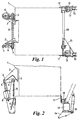
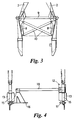
- FIG. 1 there is schematically illustrated the cab of a tractor.
- a pair of mounting horns 2 rigidly secured to the cab steelwork to the front, and strategically located at a height on the cab such that a pivotal connection 3 to spring means is at a height that approximates to the mid-height of a driver sat in the cab.
- Each horn 2 is pivoted at 3 to a respective strut 4, the strut 4 being pivoted at 5 to air spring 6, and at the opposite end pivoted at 7 to a mounting bracket 8 suitably secured to the vehicle frame or chassis.
- Bridging the mounting brackets 8 is an anti-roll bar 9 and the front suspension unit is strengthened by cross-braces 10 bridging the mounting brackets 8.
- a rear suspension system comprises mounting brackets 11,12 secured to the cab steelwork at the bottom rear transverse corner of the cab.
- a respective air spring 13 is provided, the spring to one side being mounted on a support 14 on which is also mounted a shock absorber 15 extending to the cab steelwork.
- a bracket 16 is provided to be attached to the axle casing of the tractor, there being to the opposite side a further bracket 17 also attached to the axle casing on which is located the other air spring 13 and its respective shock absorber 15 also extending to the cab steelwork.
- a transverse torque rod 18 is provided bridging the brackets 12 and 16.
- the invention provides a most effective suspension system for tractor units and fixed lorry cabs at large, and a suspension system eminently suited to an agricultural tractor that not only improves to a most significant degree the ride characteristics of the tractor, but also enables the agricultural tractor to be used on a public highway within the recommended speed limits.
Landscapes
- Engineering & Computer Science (AREA)
- Chemical & Material Sciences (AREA)
- Combustion & Propulsion (AREA)
- Transportation (AREA)
- Mechanical Engineering (AREA)
- Body Structure For Vehicles (AREA)
- Vehicle Body Suspensions (AREA)
Abstract
Description
Claims (10)
- A suspension system for the cab (1) of a tractor unit or fixed lorry characterised by a front suspension unit (4 to 8), a rear suspension unit (13 to 15) , a means (2,3) of attachment of the front of the cab to the front suspension unit, and a means (11,12,16) of attachment of the rear of the cab to the rear suspension unit, at least one of the attachments to the front and the rear of the cab being pivotal and at least one attachment being positioned at a height that is the approximate mid-height of the cab.
- A suspension system for the cab (1) of a tractor unit or fixed lorry characterised by a front suspension unit (4 to 8), a rear suspension unit (13 to 15), a means (2,3) of pivotal attachment of the front of the cab to the front suspension means, and a means (11,12,16) of pivotal attachment of the rear of the cab to the rear suspension means at least one of the pivotal attachments to the front and the rear of the cab being positioned at a height that is the approximate mid-height of the cab.
- A suspension system for the cab (1) of a tractor unit or fixed lorry as in Claim 1 or Claim 2, characterised in that the springs of the suspension unit are coil springs.
- A suspension system for the cab (1) of a tractor unit or fixed lorry as in Claim 1 or Claim 2, characterised in that the springs of the suspension unit are rubber suspension blocks.
- A suspension system for the cab (1) of a tractor unit or fixed lorry as in Claim 1 or Claim 2, characterised in that the springs of the suspension unit are air suspension springs (6,13).
- A suspension system for the cab (1) of a tractor unit or fixed lorry as in any of Claims 1 to 5, characterised in that the loading of the cab(1) on the suspension units is in the ratio 2:1 from the back to the front.
- A suspension system for the cab (1) of a tractor unit or fixed lorry as in Claim 6, characterised in that differently rated springs are employed on the front suspension unit, and on the rear suspension unit.
- A suspension system for the cab (1) of a tractor unit or fixed lorry as in Claim 6, characterised in that similarly rated springs (6,13) are employed, one spring (6) being employed on the front suspension unit and two springs (13) being employed on the rear suspension unit.
- A suspension system for the cab (1) of a tractor unit or fixed lorry as in Claim 8, characterised in that with a single spring (6) on the front suspension unit, it is located to one side of the front suspension unit and an anti-roll bar (9) is provided, extending to and pivotally attached to a support unit to the opposide side.
- A suspension system for the cab (1) of a tractor unit or fixed lorry as in any of Claims 1 to 9, characterised in that with the cab (1) being the cab of an agricultural tractor, the front suspension unit lies within the confines of the bonnet of the tractor to enable the driver to see the ground adjacent the front wheels.
Applications Claiming Priority (2)
| Application Number | Priority Date | Filing Date | Title |
|---|---|---|---|
| GB9719577 | 1997-09-16 | ||
| GBGB9719577.0A GB9719577D0 (en) | 1997-09-16 | 1997-09-16 | Suspension systems |
Publications (2)
| Publication Number | Publication Date |
|---|---|
| EP0908376A2 true EP0908376A2 (en) | 1999-04-14 |
| EP0908376A3 EP0908376A3 (en) | 2001-03-14 |
Family
ID=10819075
Family Applications (1)
| Application Number | Title | Priority Date | Filing Date |
|---|---|---|---|
| EP98116923A Withdrawn EP0908376A3 (en) | 1997-09-16 | 1998-09-08 | Suspension systems |
Country Status (4)
| Country | Link |
|---|---|
| US (1) | US6116367A (en) |
| EP (1) | EP0908376A3 (en) |
| CA (1) | CA2244281A1 (en) |
| GB (1) | GB9719577D0 (en) |
Cited By (6)
| Publication number | Priority date | Publication date | Assignee | Title |
|---|---|---|---|---|
| EP0972697A3 (en) * | 1998-07-13 | 2002-11-20 | MAN Nutzfahrzeuge Aktiengesellschaft | Front bearing for tilt cab truck |
| EP1013539A3 (en) * | 1998-12-23 | 2002-11-20 | CARL DAN. PEDDINGHAUS GMBH & CO. KG | Device for mounting cabins on utility vehicles |
| EP0972696A3 (en) * | 1998-07-13 | 2002-11-20 | MAN Nutzfahrzeuge Aktiengesellschaft | Front bearing for tilt cab truck |
| EP1661796A2 (en) | 2004-11-29 | 2006-05-31 | Renault Agriculture | Cabin suspension system |
| EP1645494A3 (en) * | 2004-10-06 | 2008-01-16 | AGCO GmbH | Utility vehicle with suspended driver's cab |
| US11173969B2 (en) | 2017-05-01 | 2021-11-16 | Agco Corporation | Four-point cab suspension system |
Families Citing this family (6)
| Publication number | Priority date | Publication date | Assignee | Title |
|---|---|---|---|---|
| US7445220B2 (en) * | 2004-02-06 | 2008-11-04 | Daimler Trucks North America Llc | Vehicle axle apparatus |
| US7540513B2 (en) * | 2005-10-25 | 2009-06-02 | Arvinmeritor Technology, Llc | Anti-roll bar and control arm assembly |
| GB0810634D0 (en) * | 2008-06-11 | 2008-07-16 | Valtra Oy Ab | Rotation system |
| US10668954B2 (en) * | 2017-11-30 | 2020-06-02 | John Payne | Cab and hood suspension with hood tilt |
| US11639202B2 (en) * | 2020-10-30 | 2023-05-02 | Volvo Truck Corporation | Truck or tractor vehicle with adjustable panhard bar and method for adjusting alignment of a truck or tractor vehicle cab relative to a truck or tractor vehicle frame |
| CN116873057B (en) * | 2023-08-08 | 2025-11-18 | 东风柳州汽车有限公司 | A cab suspension system and a commercial vehicle |
Family Cites Families (11)
| Publication number | Priority date | Publication date | Assignee | Title |
|---|---|---|---|---|
| AT285343B (en) * | 1965-10-22 | 1970-10-27 | Sune Torsten Ing Henriksson | Supporting the driver's cab of a motor vehicle |
| US3882956A (en) * | 1970-06-18 | 1975-05-13 | Chausson Usines Sa | Suspension device for vehicle drivers cab |
| DD141769B1 (en) * | 1979-01-16 | 1981-02-25 | Klaus Drechsler | VIBRATION-REDUCED DRIVER'S CABIN FOR SELF-OPERATING WORK MACHINES |
| US4451079A (en) * | 1981-06-03 | 1984-05-29 | Kabushiki Kaisha Komatsu Seisakusho | Operator's cab in a construction vehicle |
| WO1983002593A1 (en) * | 1982-01-27 | 1983-08-04 | Karl-Gunnar Andersson | Driver's seat de-vibrating device |
| US4463818A (en) * | 1982-09-07 | 1984-08-07 | Applied Power Inc. | Tilt cab truck in which the cab is partially supported by the tilting cylinder while in the drive position |
| US4452329A (en) * | 1982-12-13 | 1984-06-05 | Paccar Inc. | Suspension for a truck tilt cab |
| DE3436169A1 (en) * | 1984-10-03 | 1986-04-10 | Klöckner-Humboldt-Deutz AG, 5000 Köln | DEVICE FOR SPRING BEARING OF A TRACTOR CAB |
| ES2091469T3 (en) * | 1992-04-07 | 1996-11-01 | Volvo Ab | SUSPENSION PROVISION ON SPRINGS AND ABSORBENT OF HITS. |
| DE9312640U1 (en) * | 1992-08-31 | 1994-01-13 | Deere & Company, Niederlassung Deere & Co. European Office, Mannheim, Moline, Ill. | Driver platform suspension for vehicles |
| US5964310A (en) * | 1997-12-12 | 1999-10-12 | Caterpillar Inc. | Operator's station supporting structure |
-
1997
- 1997-09-16 GB GBGB9719577.0A patent/GB9719577D0/en not_active Ceased
-
1998
- 1998-09-08 EP EP98116923A patent/EP0908376A3/en not_active Withdrawn
- 1998-09-15 CA CA002244281A patent/CA2244281A1/en not_active Abandoned
- 1998-09-15 US US09/153,881 patent/US6116367A/en not_active Expired - Fee Related
Cited By (7)
| Publication number | Priority date | Publication date | Assignee | Title |
|---|---|---|---|---|
| EP0972697A3 (en) * | 1998-07-13 | 2002-11-20 | MAN Nutzfahrzeuge Aktiengesellschaft | Front bearing for tilt cab truck |
| EP0972696A3 (en) * | 1998-07-13 | 2002-11-20 | MAN Nutzfahrzeuge Aktiengesellschaft | Front bearing for tilt cab truck |
| EP1013539A3 (en) * | 1998-12-23 | 2002-11-20 | CARL DAN. PEDDINGHAUS GMBH & CO. KG | Device for mounting cabins on utility vehicles |
| EP1645494A3 (en) * | 2004-10-06 | 2008-01-16 | AGCO GmbH | Utility vehicle with suspended driver's cab |
| EP1661796A2 (en) | 2004-11-29 | 2006-05-31 | Renault Agriculture | Cabin suspension system |
| EP1661796A3 (en) * | 2004-11-29 | 2011-01-05 | CLAAS Tractor SAS | Cabin suspension system |
| US11173969B2 (en) | 2017-05-01 | 2021-11-16 | Agco Corporation | Four-point cab suspension system |
Also Published As
| Publication number | Publication date |
|---|---|
| CA2244281A1 (en) | 1999-03-16 |
| GB9719577D0 (en) | 1997-11-19 |
| US6116367A (en) | 2000-09-12 |
| EP0908376A3 (en) | 2001-03-14 |
Similar Documents
| Publication | Publication Date | Title |
|---|---|---|
| US6116367A (en) | Suspension systems | |
| US4057120A (en) | Front wheel drive and suspension arrangement | |
| EP1226063B1 (en) | Front axle arrangement for a heavy vehicle | |
| US4062582A (en) | Truck construction | |
| US3921999A (en) | Vehicle suspension construction and sub-assembly therefor | |
| EP0869047B1 (en) | Steerable solid axle suspension for a vehicle | |
| US5228718A (en) | Air bag and walking beam construction | |
| US6250663B1 (en) | Split frame for heavy trucks | |
| EP0301782B1 (en) | Vehicle wheel suspension unit | |
| US11964696B2 (en) | Structural frame for the body of a motor vehicle | |
| US4046212A (en) | Steerable front wheel drive transmitting mechanism | |
| US3948336A (en) | Vehicle suspension system | |
| US6923460B2 (en) | Split-frame for heavy trucks | |
| US3239235A (en) | Vehicle suspension system | |
| EP1765658A1 (en) | Device for truck cab suspension | |
| HU209091B (en) | Air-spring axle | |
| EP1454817B1 (en) | Motor-vehicle having an anti-noise frame carrying the engine and suspension units | |
| KR20260018301A (en) | Suspension of camping car | |
| KR100667427B1 (en) | McPherson suspension of automobile | |
| KR20020036321A (en) | front wheel suspension for truck | |
| JPH06143955A (en) | Rear suspension used for automobile | |
| JP2588780Y2 (en) | Shock absorber mounting structure | |
| JP2506702Y2 (en) | Cab mounting device for cab-over type vehicle | |
| ATE135313T1 (en) | COMMERCIAL VEHICLES, ESPECIALLY FRONT DRIVE TRUCKS | |
| GB2037685A (en) | A tractor unit having a fifth wheel for supporting a semi-trailer |
Legal Events
| Date | Code | Title | Description |
|---|---|---|---|
| PUAI | Public reference made under article 153(3) epc to a published international application that has entered the european phase |
Free format text: ORIGINAL CODE: 0009012 |
|
| AK | Designated contracting states |
Kind code of ref document: A2 Designated state(s): AT BE CH DE DK ES FI FR GB GR IE IT LI LU MC NL PT SE |
|
| AX | Request for extension of the european patent |
Free format text: AL;LT;LV;MK;RO;SI |
|
| PUAL | Search report despatched |
Free format text: ORIGINAL CODE: 0009013 |
|
| AK | Designated contracting states |
Kind code of ref document: A3 Designated state(s): AT BE CH CY DE DK ES FI FR GB GR IE IT LI LU MC NL PT SE |
|
| AX | Request for extension of the european patent |
Free format text: AL;LT;LV;MK;RO;SI |
|
| 17P | Request for examination filed |
Effective date: 20010405 |
|
| AKX | Designation fees paid |
Free format text: AT BE CH DE DK ES FI FR GB GR IE IT LI LU MC NL PT SE |
|
| 17Q | First examination report despatched |
Effective date: 20020909 |
|
| STAA | Information on the status of an ep patent application or granted ep patent |
Free format text: STATUS: THE APPLICATION HAS BEEN WITHDRAWN |
|
| 18W | Application withdrawn |
Effective date: 20030818 |