EP0908054B1 - Military range scoring system - Google Patents
Military range scoring system Download PDFInfo
- Publication number
- EP0908054B1 EP0908054B1 EP97944284A EP97944284A EP0908054B1 EP 0908054 B1 EP0908054 B1 EP 0908054B1 EP 97944284 A EP97944284 A EP 97944284A EP 97944284 A EP97944284 A EP 97944284A EP 0908054 B1 EP0908054 B1 EP 0908054B1
- Authority
- EP
- European Patent Office
- Prior art keywords
- imagers
- imager
- scoring
- data
- viewing
- Prior art date
- Legal status (The legal status is an assumption and is not a legal conclusion. Google has not performed a legal analysis and makes no representation as to the accuracy of the status listed.)
- Expired - Lifetime
Links
- 238000012545 processing Methods 0.000 claims abstract description 8
- 230000035945 sensitivity Effects 0.000 claims description 4
- 230000004907 flux Effects 0.000 claims description 3
- 230000005855 radiation Effects 0.000 claims 2
- 238000006073 displacement reaction Methods 0.000 claims 1
- 239000000835 fiber Substances 0.000 claims 1
- 230000006854 communication Effects 0.000 abstract description 7
- 238000004891 communication Methods 0.000 abstract description 7
- 238000004088 simulation Methods 0.000 description 5
- 238000010304 firing Methods 0.000 description 3
- 230000006870 function Effects 0.000 description 3
- 238000001514 detection method Methods 0.000 description 2
- 238000000034 method Methods 0.000 description 2
- 238000012986 modification Methods 0.000 description 2
- 230000004048 modification Effects 0.000 description 2
- 238000012549 training Methods 0.000 description 2
- 230000007175 bidirectional communication Effects 0.000 description 1
- 230000005540 biological transmission Effects 0.000 description 1
- 230000001419 dependent effect Effects 0.000 description 1
- 238000010586 diagram Methods 0.000 description 1
- 239000002360 explosive Substances 0.000 description 1
- 239000000383 hazardous chemical Substances 0.000 description 1
- 238000003384 imaging method Methods 0.000 description 1
- 230000003287 optical effect Effects 0.000 description 1
- 238000010422 painting Methods 0.000 description 1
- 229920000728 polyester Polymers 0.000 description 1
- 238000013077 scoring method Methods 0.000 description 1
- 238000009958 sewing Methods 0.000 description 1
- 238000012360 testing method Methods 0.000 description 1
Images


Classifications
-
- F—MECHANICAL ENGINEERING; LIGHTING; HEATING; WEAPONS; BLASTING
- F41—WEAPONS
- F41J—TARGETS; TARGET RANGES; BULLET CATCHERS
- F41J5/00—Target indicating systems; Target-hit or score detecting systems
- F41J5/08—Infrared hit-indicating systems
Definitions
- the present invention relates to scoring systems for military ranges.
- the armed services are required to continuously train and test the capability of troops to accurately and effectively deliver various types of ordinance to targets under battlefield conditions.
- Current methods used by the various services are limited in scope and capability.
- the shift to more extensive use of nighttime engagements has heretofore required the use in training of low level explosives (spotting charges) to determine points of impact. These charges are expensive and present both safety and environmental hazards. Many types of munitions cannot at present be scored in training scenarios.
- U.S. Patent No. 4,155,096, to Thomas et al relates to laser bore-sighting of sensors.
- U.S. Patent No. 4,222,564, to Alan et al relates to vibration sensing of impacts.
- U.S. Patent No. 4,315,689, to Goda relates to simulated firings of sight-guided missiles employing painting of the target with laser light for a period of time.
- U.S. Patent No. 4,333,106, to Love relates solely to airborne targets.
- U.S. Patent No. 4,349,838, to Daniel relates to laser bore-sighting of sensors.
- U.S. Patent No. 4,439,156, to Marshall et al relates to simulated environments and weapons firings.
- U.S. Patent No. 4,622,458, to Boeck et al relates to a system which determines trajectories of objects employing a plurality of mobile data acquisition systems connected to a central station.
- U.S. Patent No. 4,478,581, to Goda relates to simulation of firings of ballistic ammunition using lasers.
- U.S. Patent No. 4,611,993, to Brown relates to a system requiring a vertical projection screen.
- U.S. Patent No. 4,695,256, to Eichweber relates only to firearms simulations requiring a retro-reflector.
- U.S. Patent No. 4,739,329, to Ward et al relates to a system requiring radar.
- U.S. Patent No. 4,955,812, to Hill relates only to firearms simulations.
- U.S. Patent No. 5,025,424, to Rohrbaugh relates to sensing of shockwaves.
- U.S. Patent No. 5,228,854, to Eldridge relates to a pure simulation system.
- the present invention provides a scoring system capable of detecting and reporting delivery of a wide variety of ordinance in real time under daytime and nighttime conditions. Once calibrated, the system is straightforward to set up and use, including automatic selection of targets.
- the present invention is of a military range scoring apparatus according to claim 1. Preferred embodiments are set out in the dependent claims.
- a primary object of the present invention is to provide a scoring system capable of detecting and accurately reporting delivery of a wide variety of ordinance.
- Another object of the present invention is to provide a scoring system capable of functioning under both daytime and nighttime conditions.
- a primary advantage of the present invention is that it provides for automatic selection of targets.
- the present invention is of an ordinance scoring system employing, preferably, both optical and thermal imagers which can operate in multiple lighting conditions.
- the imagers sense visible light, near infrared, infrared, and military laser designators simultaneously with the ability to overlay each onto the others.
- the output of the sensor is a video-like presentation displaying different energy levels rather than light levels. By sensing the energy levels of each object in the field of view, the imager works as well in the absence of light as it does in visibly bright conditions. Accordingly, the sensor will operate under all day and night ambient conditions and can detect the impact of every type of ordinance now in use as well as a laser spot designator illuminating targets for smart weapons.
- the sensor can also track the "fly in" path of many weapons that are adequately heated by air resistance during delivery.
- the present invention also incorporates a control system which, when calibrated, will automatically position the imager on any selected target with high azimuth and inclination accuracy, such as of 0.05% error or less.
- the miss distance between the target and the weapon impact can then be calculated using multiple sensor azimuth triangulation or single sensor azimuth and inclination differences.
- the operator interfaces to the scoring system through a computer, preferably an IBM-PC compatible system running a Windows (trademark of Microsoft Corporation) operating system.
- a computer preferably an IBM-PC compatible system running a Windows (trademark of Microsoft Corporation) operating system.
- scoring ordinance and repositioning the system to different targets is accomplished by a simple series of two or three clicks of the mouse, trackball, touch screen, or like input device.
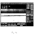
- the video from the sensor or sensors is digitized and displayed on the same computer screen used to control the system's operation and to score the weapon.
- the video can be frozen at the point of ordinance impact to allow very accurate cursor positioning and scoring.
- the digitized video can be saved and retrieved on a frame-by-frame basis and re-processed, if required.
- the use of digital signal processing on the digitized video facilitates the implementation of automated scoring methods.
- a fully automated version of the invention senses the moment of impact and scores its location with no operator intervention.
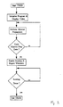
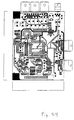
- Figs. 1-3 these provide flowcharts of the high level logic of the scoring and control computer 24 of the invention, which is shown in Fig. 5.
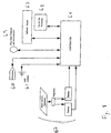
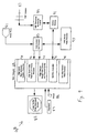
- the preferred controller diagramed on Fig. 4, comprises microcomputer 10, supplied by power 16 and power supply voltage regulators, filters, and reset circuitry 18.
- the microcomputer communicates with modem 14 to provide two-way communication with the scoring and control computer via radio transceiver 12 and antenna 11.
- Serial port 20 provides communication to flux gate compass and inclinometer 36, which provides both digital 26 and analog 28 inputs back to the microcomputer.
- Communication with microwave units 38, video switcher and control 40 , imager control 42 , and pan and tilt control 44 is provided via analog input 28, buffered analog input 30, buffered digital output 32, and power driver 34.
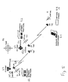
- Fig. 5 illustrates a typical system of the invention.
- Scoring and control computer 24 receives via microwave 46 and communicates via VHF radio, antenna/modem 12,14,11 to, in this case, two imaging sites sending transmissions by microwave 50,60 and receiving communications by VHF antennas 51,61.
- Each site comprises a system controller 55,65, photoelectric and battery power supply means 52,62, a positioner 54,64, and an infrared imager 53,63.
- the imagers at the sites are controlled by the system controller on commands from the scoring and control computer as needed to observe target(s) 99.
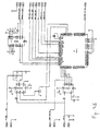
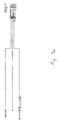
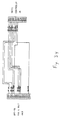
- Fig. 6 illustrates a long range infrared imager system of the invention, with controller 55 , positioner 54 , infrared imager 53 , compass position sensor 56, and sunshade 57.
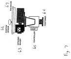
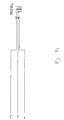
- Fig. 7 illustrates a second type long range laser infrared imager system of the invention, with controller 65, positioner 64, infrared imager 63, compass position sensor 66, and sunshade 67.
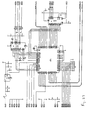
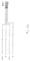
- Fig. 8 illustrates an imager site, showing the interconnections to and the central role of the controller 65, with the photoelectric generator, regulator, and batteries 62, VHF antenna 61 , microwave antenna 60, flux gate compass and inclinometer 69, infrared imager 63, and pan and tilt positioner 68.
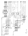
- Fig. 9 illustrates a scoring position, with scoring and control computer 88, preferably having high speed and high resolution graphics controller 90, high speed video digitizer and overlay processor 92 , high capacity digital video storage and playback system 94, interface controller 96, 166 MHz or faster Intel Pentium, Pentium Pro, or Pentium II processor 98, large format high resolution monitor 82, keyboard 84, and mouse/trackball 86.
- Input is received from microwave unit 81 and video switch and processor 83 and output is through VHF antenna 87, VHF transceiver 89, and control modem 91.
- video input may be simultaneously stored on VHS format video recorder 85 or the like.
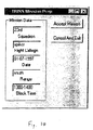
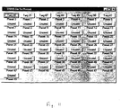
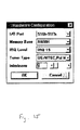
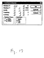
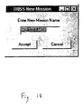
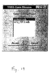
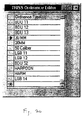
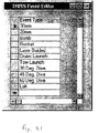
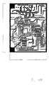
- Figs. 10-21 illustrate the types of screens useful in any software according to the invention. Attention is particularly drawn to Fig. 12, which illustrates one embodiment of the main control screen during a mission. In this example, two remote imagers are being viewed and controlled simultaneously, while other setups will allow varying numbers of imagers. Specialized hardware useful in the present invention are shown in Figs. 23-34.
- the following status conditions may preferably be read back on command: Azimuth, Elevation, Field of View, Contrast, Polarity, Sensitivity, Focus, Power Supply Voltage, Temperature, Ambient Light Condition, User Designated Alarm Conditions Communications Link Direct Interface RS-232 RS-422/485 (optional) Modem (optional) Internal 300 Baud to 2400 Baud Radio (optional) VHF or UHF Transceiver
Landscapes
- General Engineering & Computer Science (AREA)
- Engineering & Computer Science (AREA)
- Aiming, Guidance, Guns With A Light Source, Armor, Camouflage, And Targets (AREA)
- Closed-Circuit Television Systems (AREA)
- Absorbent Articles And Supports Therefor (AREA)
- Paper (AREA)
- Air Bags (AREA)
- Measurement Of The Respiration, Hearing Ability, Form, And Blood Characteristics Of Living Organisms (AREA)
- Measurement Of Unknown Time Intervals (AREA)
- Time Recorders, Dirve Recorders, Access Control (AREA)
- Ultra Sonic Daignosis Equipment (AREA)
- Force Measurement Appropriate To Specific Purposes (AREA)
- Optical Radar Systems And Details Thereof (AREA)
Abstract
Description
| Power Input: | |
| Imager Power | 12VDC 2A |
| Pan&Tilt Power | 12VDC to 28VDC 2A |
| Controller power | 12VDC 0.18A |
| Radio Power | 12VDC 0.06A Receive |
| 12VDC 0.90A Transmit | |
| Auxiliary Power | 220VDC/AC 10.0A |
| Position Control | |
| Azimuth Motor Control | Variable from 0% to 1Q0% |
| Azimuth Motor Drive | 6VDC to 28VDC 2A |
| Elevation Motor Control | Variable from 0% to 100% |
| Elevation Motor Drive | 6VDC to 28VDC 2A |
| Position Sensing | |
| Coupled Potentiometer | 1.5° Resolution from Rotational Stop |
| 1.0° Inclination from Horizontal | |
| Standard Compass | 1.0° Resolution from Magnetic North |
| 1.0° Inclination from Horizontal | |
| High Resolution Compass | 0.1° Resolution from Magnetic North |
| 0.1° Inclination from Horizontal |
| Imager Control | |
| Power | Off On (switchable) |
| Cool Down | Status Indication Reportable |
| Sensitivity | -5VDC to +5VDC (continuously variable) |
| Field of View | Narrow or Wide (switchable) |
| Electro-optical Zoom | X1 X2 X4 or continuous zoom (switchable) |
| Width Calibration | -5VDC to +5VDC (absolute sewing) |
| Phase Calibration | -5VDC to +SVDC (absolute setting) |
| Contrast | Low Medium High (switchable) or -5VDC to +5VDC (continuously variable) |
| Polarity | Black Hot / White Hot (switchable) |
| Focus | Wide FOV Near / Far (relative setting) |
| Narrow FOV Near / Far (relative setting) | |
| Case Temperature | Status Indication Reportable |
| Control Addressability | |
| Discrete Addresses | 225 individually addressable controllers |
| Broadcast | To all 225 controllers at the same time |
| Group Address | 25 assignable subgroup addresses |
| Preset Locations | |
| Stored Presets | 50 presets stored in non-volatile memory |
| Download | Real time down load of Azimuth, Elevation, Field of View, Contrast, Polarity, Sensitivity, and Focus |
| Communications Link | |
| Direct Interface | RS-232 |
| RS-422/485 (optional) | |
| Modem (optional) | |
| Radio (optional) | VHF or UHF Transceiver |
Claims (13)
- A military range scoring apparatus comprising a plurality of imagers (53,63) for viewing a plurality of reference points and corresponding impact points of ordinance aimed at the reference points, remote means (24) for processing and viewing data received from said imagers, and means (11,12,14,51) for communicating data between said imagers and said remote means (24), characterized in that :wherein said remote means for processing and viewing data comprises a computer (24,88) and display (82) providing for simultaneous viewing of data from a plurality of imagers.said remote means are adapted for controlling said imagers and comprise a computer (24,88) for storing imager pointing, setup, and calibration data for the plurality of reference points; andsaid apparatus further comprises a database of reference points and imagers locations to allow rapid and accurate calculation of impact points ; andmeans (11,12,14) for communicating control information between said imagers and said remote means; and
- The apparatus of claim 1 wherein said data comprise video images calibrated for angular displacement across a horizontal axis.
- The apparatus of claim 1 wherein said communicating means comprise means selected from the group consisting of microwave, radio, fiber optic line, and wire line.
- The apparatus of claim 1 wherein said imagers comprise control means (64) to communicate with a positioner (54,64) used to aim an imager at a reference point by changing azimuth and elevation of said imager.
- The apparatus of claim 1 wherein said imagers comprise imagers sensitive to infrared radiation.
- The apparatus of claim 5 wherein said infrared imagers comprise means for sensing laser radiation used to target and guide smart weapons.
- The apparatus of claim 1 wherein said imagers comprise flux gate compasses (69) used to sense imager horizontal pointing angle, to allow accurate horizontal positioning and status information provided to said controlling means.
- The apparatus of claim 1 wherein said imagers comprise inclinometers (69) used to sense imager vertical pointing angle, to allow accurate vertical positioning and status information provided to said controlling means.
- The apparatus of claim 1 wherein said imagers comprise control means (64) for setting imager parameters including field of view, zoom, focus, sensitivity, and contrast.
- The apparatus of claim 1 wherein said means for viewing data comprises means (92) for digitizing a video image.
- The apparatus of claim 10 wherein said processing means comprises digital signal processing means for determining angular offsets and scoring an impact point from said digitized video image.
- The apparatus of claim 11 wherein said digital signal processing means comprise means for detecting multiple impacts and scoring impact points without user intervention.
- The apparatus of claim 10 additionally comprising means (94) for storing and retrieving said digitized video image.
Applications Claiming Priority (5)
| Application Number | Priority Date | Filing Date | Title |
|---|---|---|---|
| US1848996P | 1996-05-30 | 1996-05-30 | |
| US18489P | 1996-05-30 | ||
| US08/864,851 US5999210A (en) | 1996-05-30 | 1997-05-29 | Military range scoring system |
| US864851 | 1997-05-29 | ||
| PCT/US1997/009580 WO1997048962A2 (en) | 1996-05-30 | 1997-05-30 | Military range scoring system |
Publications (3)
| Publication Number | Publication Date |
|---|---|
| EP0908054A2 EP0908054A2 (en) | 1999-04-14 |
| EP0908054A4 EP0908054A4 (en) | 2000-05-24 |
| EP0908054B1 true EP0908054B1 (en) | 2003-03-26 |
Family
ID=26691178
Family Applications (1)
| Application Number | Title | Priority Date | Filing Date |
|---|---|---|---|
| EP97944284A Expired - Lifetime EP0908054B1 (en) | 1996-05-30 | 1997-05-30 | Military range scoring system |
Country Status (8)
| Country | Link |
|---|---|
| US (2) | US5999210A (en) |
| EP (1) | EP0908054B1 (en) |
| AT (1) | ATE235784T1 (en) |
| AU (1) | AU724543B2 (en) |
| DE (1) | DE69720215T2 (en) |
| DK (1) | DK0908054T3 (en) |
| ES (1) | ES2192694T3 (en) |
| WO (1) | WO1997048962A2 (en) |
Families Citing this family (27)
| Publication number | Priority date | Publication date | Assignee | Title |
|---|---|---|---|---|
| US5999210A (en) * | 1996-05-30 | 1999-12-07 | Proteus Corporation | Military range scoring system |
| US20040014010A1 (en) * | 1997-08-25 | 2004-01-22 | Swensen Frederick B. | Archery laser training system and method of simulating weapon operation |
| DE69828412T2 (en) * | 1997-08-25 | 2005-06-23 | Beamhit L.L.C. | LASER WORKING TOOLS WHICH ARE CONNECTED TO A NETWORK |
| WO2001051875A2 (en) | 2000-01-13 | 2001-07-19 | Beamhit, Llc | Firearm laser training system and method employing modified blank cartridges for simulating operation of a firearm |
| WO2001094872A2 (en) | 2000-06-09 | 2001-12-13 | Beamhit, Llc | Firearm laser training system and method facilitating firearm training with various targets and visual feedback of simulated projectile impact locations |
| WO2002101318A2 (en) | 2001-06-08 | 2002-12-19 | Beamhit, Llc | Firearm laser training system and method facilitating firearm training for extended range targets with feedback of firearm control |
| US7386187B2 (en) * | 2004-03-07 | 2008-06-10 | Rafael Advanced Defense Systems Ltd. | Method and system for pseudo-autonomous image registration |
| US8483567B2 (en) * | 2004-04-09 | 2013-07-09 | Immediate Response Technologies, Inc | Infrared communication system and method |
| EP1763683B1 (en) * | 2004-07-02 | 2016-04-06 | Trackman A/S | A method and apparatus for determining a deviation between an actual direction of a launched projectile and a predetermined direction |
| US9645235B2 (en) | 2005-03-03 | 2017-05-09 | Trackman A/S | Determination of spin parameters of a sports ball |
| CN101384308B (en) * | 2005-03-03 | 2011-07-27 | 竞技者公司 | Determination of spin parameters of a sports ball |
| US10393870B2 (en) | 2005-03-03 | 2019-08-27 | Trackman A/S | Determination of spin parameters of a sports ball |
| US8360776B2 (en) | 2005-10-21 | 2013-01-29 | Laser Shot, Inc. | System and method for calculating a projectile impact coordinates |
| US20070160960A1 (en) * | 2005-10-21 | 2007-07-12 | Laser Shot, Inc. | System and method for calculating a projectile impact coordinates |
| JP5469894B2 (en) * | 2008-07-05 | 2014-04-16 | 株式会社トプコン | Surveying device and automatic tracking method |
| KR102033703B1 (en) | 2009-01-29 | 2019-10-17 | 트랙맨 에이/에스 | An assembly comprising a radar and an imaging element |
| JP5469899B2 (en) * | 2009-03-31 | 2014-04-16 | 株式会社トプコン | Automatic tracking method and surveying device |
| EP2605036B1 (en) | 2011-12-16 | 2019-10-23 | Trackman A/S | A method and a sensor for determining a direction-of-arrival of impingent radiation |
| US8620464B1 (en) * | 2012-02-07 | 2013-12-31 | The United States Of America As Represented By The Secretary Of The Navy | Visual automated scoring system |
| RU2516205C2 (en) * | 2012-03-27 | 2014-05-20 | Федеральное государственное военное образовательное учреждение высшего профессионального образования "Военный авиационный инженерный университет" (г. Воронеж) Министерства обороны Российской Федерации | Method of charge fall point coordinates determination |
| TR201608513A2 (en) * | 2016-06-21 | 2018-01-22 | Havelsan Hava Elektronik Sanayi Ve Ticaret Anonim Sirketi | Visual ammunition and laser evaluation system |
| US10379214B2 (en) | 2016-07-11 | 2019-08-13 | Trackman A/S | Device, system and method for tracking multiple projectiles |
| US10048043B2 (en) | 2016-07-12 | 2018-08-14 | Paul Rahmanian | Target carrier with virtual targets |
| US10444339B2 (en) | 2016-10-31 | 2019-10-15 | Trackman A/S | Skid and roll tracking system |
| US10989791B2 (en) | 2016-12-05 | 2021-04-27 | Trackman A/S | Device, system, and method for tracking an object using radar data and imager data |
| CN108154878A (en) * | 2017-12-12 | 2018-06-12 | 北京小米移动软件有限公司 | Control the method and device of monitoring device |
| CA3228332A1 (en) * | 2021-08-06 | 2023-02-09 | Bae Systems Plc | Improvements in and relating to laser designator pods (ldp) |
Family Cites Families (35)
| Publication number | Priority date | Publication date | Assignee | Title |
|---|---|---|---|---|
| US3624401A (en) | 1969-10-06 | 1971-11-30 | Us Navy | Ultraviolet target hit scoring system |
| CA1005147A (en) | 1971-02-23 | 1977-02-08 | Colin M. Finch | Indicating the passing of a projectile through an area in space |
| US3798795A (en) | 1972-07-03 | 1974-03-26 | Rmc Res Corp | Weapon aim evaluation system |
| US3793481A (en) * | 1972-11-20 | 1974-02-19 | Celesco Industries Inc | Range scoring system |
| SE392644B (en) | 1973-11-19 | 1977-04-04 | Saab Scania Ab | PROCEDURE AND DEVICE FOR CARRYING OUT A QUANTITATIVE SUMMARY CONTROL OF FIRE PREPARATIONS, TEMPLE FOLLOWING IN APPLICATION EXERCISES WITH SIMULATED FIRE DEPARTMENT AGAINST A FLYING FIRE TARGET AT AN AIRCRAFT STRAP |
| US4155096A (en) * | 1977-03-22 | 1979-05-15 | Martin Marietta Corporation | Automatic laser boresighting |
| US4222564A (en) * | 1977-06-13 | 1980-09-16 | Aba Electromechanical Systems, Inc. | Automated scoring target system |
| US4225867A (en) * | 1978-09-19 | 1980-09-30 | Gell Harold A | Orientation system |
| DE2846962C2 (en) * | 1978-10-27 | 1981-02-05 | Precitronic Gesellschaft Fuer Feinmechanik Und Electronic Mbh, 2000 Hamburg | Laser light shot simulator for guided missiles |
| FR2445944B1 (en) * | 1979-01-08 | 1984-11-09 | Australasian Training Aids Pty | |
| DE3069857D1 (en) * | 1979-05-04 | 1985-02-07 | Gunter Lowe | Method of measuring shooting errors and shooting error measurement device for carrying out the method |
| FR2475208A1 (en) * | 1980-02-01 | 1981-08-07 | Thomson Csf | LASER OBJECTIVE DESIGNATION SYSTEM |
| DE3114000C2 (en) * | 1981-04-07 | 1983-04-28 | Precitronic Gesellschaft für Feinmechanik und Electronic mbH, 2000 Hamburg | Methods of shooting simulation and training for ballistic ammunition and moving targets |
| US4439156A (en) * | 1982-01-11 | 1984-03-27 | The United States Of America As Represented By The Secretary Of The Navy | Anti-armor weapons trainer |
| DE3244255A1 (en) * | 1982-11-30 | 1984-06-14 | Messerschmitt-Bölkow-Blohm GmbH, 8012 Ottobrunn | RAIL SURVEYING AND MONITORING SYSTEM |
| US4611993A (en) * | 1984-05-31 | 1986-09-16 | The United States Of America As Represented By The Secretary Of The Army | Laser projected live fire evasive target system |
| US4695256A (en) * | 1984-12-31 | 1987-09-22 | Precitronic Gesellschaft | Method for practicing aiming with the use of a laser firing simulator and of a retroreflector on the target side, as well as firing simulator for carrying out this method |
| US4689016A (en) * | 1984-12-31 | 1987-08-25 | Precitronic Gesellschaft Fur Feinmechanik Und Electronic Mbh | Firing simulator for practicing aiming with a firearm |
| CA1231174A (en) * | 1985-06-28 | 1988-01-05 | Daniel Lamarre | Tracking simulator |
| US4739329A (en) * | 1986-04-16 | 1988-04-19 | Motorola, Inc. | Scaler scoring system |
| US5029866A (en) * | 1988-06-20 | 1991-07-09 | Beard Iii Bryce P | Apparatus and method for determining projectile impact locations |
| US4955812A (en) * | 1988-08-04 | 1990-09-11 | Hill Banford R | Video target training apparatus for marksmen, and method |
| US5291262A (en) * | 1989-03-27 | 1994-03-01 | Dunne Jeremy G | Laser surveying instrument |
| DE3941144C2 (en) * | 1989-12-13 | 1994-01-13 | Zeiss Carl Fa | Coordinate measuring device for the contactless measurement of an object |
| US5025424A (en) * | 1990-05-21 | 1991-06-18 | Rohrbaugh George W | Shock wave scoring apparatus employing curved rod sensors |
| US5141175A (en) * | 1991-03-22 | 1992-08-25 | Harris Gordon L | Air launched munition range extension system and method |
| US5228854A (en) * | 1992-07-21 | 1993-07-20 | Teledyne, Inc. | Combat training system and method |
| US5359920A (en) * | 1992-12-15 | 1994-11-01 | Hughes Aircraft Company | Munition impact point indicator and automatic gun aimpoint correction system |
| US5432546A (en) * | 1992-12-21 | 1995-07-11 | Enel Company | Weapon impact assessment system |
| US5528515A (en) * | 1993-08-23 | 1996-06-18 | Dainippon Screen Mfg. Co., Ltd. | Image proofing apparatus for gravure printing |
| US5521634A (en) * | 1994-06-17 | 1996-05-28 | Harris Corporation | Automatic detection and prioritized image transmission system and method |
| US5528518A (en) * | 1994-10-25 | 1996-06-18 | Laser Technology, Inc. | System and method for collecting data used to form a geographic information system database |
| US5644386A (en) * | 1995-01-11 | 1997-07-01 | Loral Vought Systems Corp. | Visual recognition system for LADAR sensors |
| US5689445A (en) * | 1996-04-05 | 1997-11-18 | Rowe-Deines Instruments Incorporated | Electronic compass and attitude sensing system |
| US5999210A (en) * | 1996-05-30 | 1999-12-07 | Proteus Corporation | Military range scoring system |
-
1997
- 1997-05-29 US US08/864,851 patent/US5999210A/en not_active Expired - Lifetime
- 1997-05-30 ES ES97944284T patent/ES2192694T3/en not_active Expired - Lifetime
- 1997-05-30 EP EP97944284A patent/EP0908054B1/en not_active Expired - Lifetime
- 1997-05-30 WO PCT/US1997/009580 patent/WO1997048962A2/en not_active Ceased
- 1997-05-30 DE DE69720215T patent/DE69720215T2/en not_active Expired - Fee Related
- 1997-05-30 AU AU45815/97A patent/AU724543B2/en not_active Ceased
- 1997-05-30 AT AT97944284T patent/ATE235784T1/en not_active IP Right Cessation
- 1997-05-30 DK DK97944284T patent/DK0908054T3/en active
-
1999
- 1999-06-01 US US09/323,578 patent/US6198501B1/en not_active Expired - Fee Related
Also Published As
| Publication number | Publication date |
|---|---|
| WO1997048962A2 (en) | 1997-12-24 |
| DE69720215D1 (en) | 2003-04-30 |
| EP0908054A2 (en) | 1999-04-14 |
| ES2192694T3 (en) | 2003-10-16 |
| US6198501B1 (en) | 2001-03-06 |
| AU724543B2 (en) | 2000-09-28 |
| EP0908054A4 (en) | 2000-05-24 |
| US5999210A (en) | 1999-12-07 |
| DE69720215T2 (en) | 2004-03-04 |
| DK0908054T3 (en) | 2003-07-21 |
| ATE235784T1 (en) | 2003-04-15 |
| AU4581597A (en) | 1998-01-07 |
| WO1997048962A3 (en) | 1998-02-26 |
Similar Documents
| Publication | Publication Date | Title |
|---|---|---|
| EP0908054B1 (en) | Military range scoring system | |
| WO1997048962A9 (en) | Military range scoring system | |
| US5379676A (en) | Fire control system | |
| US6769347B1 (en) | Dual elevation weapon station and method of use | |
| US4672435A (en) | Observation and reconnaissance system for armored vehicles | |
| US5026158A (en) | Apparatus and method for displaying and storing impact points of firearm projectiles on a sight field of view | |
| US4695161A (en) | Automatic ranging gun sight | |
| US5822713A (en) | Guided fire control system | |
| US4004487A (en) | Missile fire-control system and method | |
| KR920006525B1 (en) | Gun fire control system | |
| CA1208431A (en) | Fire simulation device for training in the operation of shoulder weapons and the like | |
| US4611771A (en) | Fiber optic track/reaim system | |
| US4538991A (en) | Target apparatus for weapon fire training | |
| US4885977A (en) | Stabilized line-of-sight aiming system for use with fire control systems | |
| US4777861A (en) | Missile aiming sight | |
| US4789339A (en) | Gunnery training system | |
| US20220214140A1 (en) | Grenade launcher aiming control system | |
| CA2258945C (en) | Military range scoring system | |
| RU2224206C1 (en) | Optical sight of fire control system (modifications) | |
| JPH0357400B2 (en) | ||
| EP0065832A1 (en) | A gun aiming arrangement | |
| JP2001194092A (en) | Range safety monitoring device | |
| RU4621U1 (en) | INFORMATION PROCESSING DEVICE FOR MANAGING ARTILLERY FIRE | |
| Hougen et al. | Description of the RSTA Subsystem | |
| JPH0152679B2 (en) |
Legal Events
| Date | Code | Title | Description |
|---|---|---|---|
| PUAI | Public reference made under article 153(3) epc to a published international application that has entered the european phase |
Free format text: ORIGINAL CODE: 0009012 |
|
| 17P | Request for examination filed |
Effective date: 19981229 |
|
| AK | Designated contracting states |
Kind code of ref document: A2 Designated state(s): AT BE CH DE DK ES FI FR GB GR IE IT LI LU MC NL PT SE |
|
| A4 | Supplementary search report drawn up and despatched |
Effective date: 20000410 |
|
| AK | Designated contracting states |
Kind code of ref document: A4 Designated state(s): AT BE CH DE DK ES FI FR GB GR IE IT LI LU MC NL PT SE |
|
| 17Q | First examination report despatched |
Effective date: 20020218 |
|
| GRAH | Despatch of communication of intention to grant a patent |
Free format text: ORIGINAL CODE: EPIDOS IGRA |
|
| GRAH | Despatch of communication of intention to grant a patent |
Free format text: ORIGINAL CODE: EPIDOS IGRA |
|
| GRAA | (expected) grant |
Free format text: ORIGINAL CODE: 0009210 |
|
| AK | Designated contracting states |
Designated state(s): AT BE CH DE DK ES FI FR GB GR IE IT LI LU MC NL PT SE |
|
| PG25 | Lapsed in a contracting state [announced via postgrant information from national office to epo] |
Ref country code: NL Free format text: LAPSE BECAUSE OF FAILURE TO SUBMIT A TRANSLATION OF THE DESCRIPTION OR TO PAY THE FEE WITHIN THE PRESCRIBED TIME-LIMIT Effective date: 20030326 Ref country code: FI Free format text: LAPSE BECAUSE OF FAILURE TO SUBMIT A TRANSLATION OF THE DESCRIPTION OR TO PAY THE FEE WITHIN THE PRESCRIBED TIME-LIMIT Effective date: 20030326 |
|
| REG | Reference to a national code |
Ref country code: GB Ref legal event code: FG4D |
|
| REG | Reference to a national code |
Ref country code: CH Ref legal event code: EP |
|
| REF | Corresponds to: |
Ref document number: 69720215 Country of ref document: DE Date of ref document: 20030430 Kind code of ref document: P |
|
| REG | Reference to a national code |
Ref country code: IE Ref legal event code: FG4D |
|
| PG25 | Lapsed in a contracting state [announced via postgrant information from national office to epo] |
Ref country code: LU Free format text: LAPSE BECAUSE OF NON-PAYMENT OF DUE FEES Effective date: 20030530 Ref country code: IE Free format text: LAPSE BECAUSE OF NON-PAYMENT OF DUE FEES Effective date: 20030530 |
|
| PG25 | Lapsed in a contracting state [announced via postgrant information from national office to epo] |
Ref country code: MC Free format text: LAPSE BECAUSE OF NON-PAYMENT OF DUE FEES Effective date: 20030531 |
|
| PG25 | Lapsed in a contracting state [announced via postgrant information from national office to epo] |
Ref country code: SE Free format text: LAPSE BECAUSE OF FAILURE TO SUBMIT A TRANSLATION OF THE DESCRIPTION OR TO PAY THE FEE WITHIN THE PRESCRIBED TIME-LIMIT Effective date: 20030626 Ref country code: PT Free format text: LAPSE BECAUSE OF FAILURE TO SUBMIT A TRANSLATION OF THE DESCRIPTION OR TO PAY THE FEE WITHIN THE PRESCRIBED TIME-LIMIT Effective date: 20030626 |
|
| REG | Reference to a national code |
Ref country code: GR Ref legal event code: EP Ref document number: 20030402298 Country of ref document: GR |
|
| REG | Reference to a national code |
Ref country code: DK Ref legal event code: T3 |
|
| REG | Reference to a national code |
Ref country code: CH Ref legal event code: NV Representative=s name: PATENTANWAELTE FELDMANN & PARTNER AG |
|
| NLV1 | Nl: lapsed or annulled due to failure to fulfill the requirements of art. 29p and 29m of the patents act | ||
| REG | Reference to a national code |
Ref country code: ES Ref legal event code: FG2A Ref document number: 2192694 Country of ref document: ES Kind code of ref document: T3 |
|
| ET | Fr: translation filed | ||
| PLBE | No opposition filed within time limit |
Free format text: ORIGINAL CODE: 0009261 |
|
| STAA | Information on the status of an ep patent application or granted ep patent |
Free format text: STATUS: NO OPPOSITION FILED WITHIN TIME LIMIT |
|
| REG | Reference to a national code |
Ref country code: IE Ref legal event code: MM4A |
|
| 26N | No opposition filed |
Effective date: 20031230 |
|
| PGFP | Annual fee paid to national office [announced via postgrant information from national office to epo] |
Ref country code: DK Payment date: 20060529 Year of fee payment: 10 |
|
| PGFP | Annual fee paid to national office [announced via postgrant information from national office to epo] |
Ref country code: AT Payment date: 20060530 Year of fee payment: 10 Ref country code: GR Payment date: 20060530 Year of fee payment: 10 |
|
| PGFP | Annual fee paid to national office [announced via postgrant information from national office to epo] |
Ref country code: ES Payment date: 20060531 Year of fee payment: 10 |
|
| PGFP | Annual fee paid to national office [announced via postgrant information from national office to epo] |
Ref country code: BE Payment date: 20060613 Year of fee payment: 10 |
|
| PGFP | Annual fee paid to national office [announced via postgrant information from national office to epo] |
Ref country code: DE Payment date: 20060726 Year of fee payment: 10 |
|
| PGFP | Annual fee paid to national office [announced via postgrant information from national office to epo] |
Ref country code: CH Payment date: 20070625 Year of fee payment: 11 |
|
| PGFP | Annual fee paid to national office [announced via postgrant information from national office to epo] |
Ref country code: GB Payment date: 20070618 Year of fee payment: 11 |
|
| BERE | Be: lapsed |
Owner name: *PROTEUS CORP. Effective date: 20070531 |
|
| PGFP | Annual fee paid to national office [announced via postgrant information from national office to epo] |
Ref country code: IT Payment date: 20070627 Year of fee payment: 11 |
|
| REG | Reference to a national code |
Ref country code: DK Ref legal event code: EBP |
|
| PG25 | Lapsed in a contracting state [announced via postgrant information from national office to epo] |
Ref country code: AT Free format text: LAPSE BECAUSE OF NON-PAYMENT OF DUE FEES Effective date: 20070530 |
|
| PG25 | Lapsed in a contracting state [announced via postgrant information from national office to epo] |
Ref country code: BE Free format text: LAPSE BECAUSE OF NON-PAYMENT OF DUE FEES Effective date: 20070531 |
|
| PG25 | Lapsed in a contracting state [announced via postgrant information from national office to epo] |
Ref country code: DK Free format text: LAPSE BECAUSE OF NON-PAYMENT OF DUE FEES Effective date: 20070531 Ref country code: DE Free format text: LAPSE BECAUSE OF NON-PAYMENT OF DUE FEES Effective date: 20071201 |
|
| PGFP | Annual fee paid to national office [announced via postgrant information from national office to epo] |
Ref country code: FR Payment date: 20070619 Year of fee payment: 11 |
|
| REG | Reference to a national code |
Ref country code: ES Ref legal event code: FD2A Effective date: 20070531 |
|
| PG25 | Lapsed in a contracting state [announced via postgrant information from national office to epo] |
Ref country code: GR Free format text: LAPSE BECAUSE OF NON-PAYMENT OF DUE FEES Effective date: 20071204 Ref country code: ES Free format text: LAPSE BECAUSE OF NON-PAYMENT OF DUE FEES Effective date: 20070531 |
|
| REG | Reference to a national code |
Ref country code: CH Ref legal event code: PL |
|
| GBPC | Gb: european patent ceased through non-payment of renewal fee |
Effective date: 20080530 |
|
| PG25 | Lapsed in a contracting state [announced via postgrant information from national office to epo] |
Ref country code: LI Free format text: LAPSE BECAUSE OF NON-PAYMENT OF DUE FEES Effective date: 20080531 Ref country code: CH Free format text: LAPSE BECAUSE OF NON-PAYMENT OF DUE FEES Effective date: 20080531 |
|
| REG | Reference to a national code |
Ref country code: FR Ref legal event code: ST Effective date: 20090119 |
|
| PG25 | Lapsed in a contracting state [announced via postgrant information from national office to epo] |
Ref country code: FR Free format text: LAPSE BECAUSE OF NON-PAYMENT OF DUE FEES Effective date: 20080602 |
|
| PG25 | Lapsed in a contracting state [announced via postgrant information from national office to epo] |
Ref country code: GB Free format text: LAPSE BECAUSE OF NON-PAYMENT OF DUE FEES Effective date: 20080530 |
|
| PG25 | Lapsed in a contracting state [announced via postgrant information from national office to epo] |
Ref country code: IT Free format text: LAPSE BECAUSE OF NON-PAYMENT OF DUE FEES Effective date: 20080530 |