EP0907973B1 - A thermoelectric generator unit - Google Patents
A thermoelectric generator unit Download PDFInfo
- Publication number
- EP0907973B1 EP0907973B1 EP97916684A EP97916684A EP0907973B1 EP 0907973 B1 EP0907973 B1 EP 0907973B1 EP 97916684 A EP97916684 A EP 97916684A EP 97916684 A EP97916684 A EP 97916684A EP 0907973 B1 EP0907973 B1 EP 0907973B1
- Authority
- EP
- European Patent Office
- Prior art keywords
- plates
- elements
- housing
- connector
- element rows
- Prior art date
- Legal status (The legal status is an assumption and is not a legal conclusion. Google has not performed a legal analysis and makes no representation as to the accuracy of the status listed.)
- Expired - Lifetime
Links
Images


Classifications
-
- H—ELECTRICITY
- H10—SEMICONDUCTOR DEVICES; ELECTRIC SOLID-STATE DEVICES NOT OTHERWISE PROVIDED FOR
- H10N—ELECTRIC SOLID-STATE DEVICES NOT OTHERWISE PROVIDED FOR
- H10N10/00—Thermoelectric devices comprising a junction of dissimilar materials, i.e. devices exhibiting Seebeck or Peltier effects
- H10N10/10—Thermoelectric devices comprising a junction of dissimilar materials, i.e. devices exhibiting Seebeck or Peltier effects operating with only the Peltier or Seebeck effects
- H10N10/13—Thermoelectric devices comprising a junction of dissimilar materials, i.e. devices exhibiting Seebeck or Peltier effects operating with only the Peltier or Seebeck effects characterised by the heat-exchanging means at the junction
-
- H—ELECTRICITY
- H10—SEMICONDUCTOR DEVICES; ELECTRIC SOLID-STATE DEVICES NOT OTHERWISE PROVIDED FOR
- H10N—ELECTRIC SOLID-STATE DEVICES NOT OTHERWISE PROVIDED FOR
- H10N10/00—Thermoelectric devices comprising a junction of dissimilar materials, i.e. devices exhibiting Seebeck or Peltier effects
- H10N10/10—Thermoelectric devices comprising a junction of dissimilar materials, i.e. devices exhibiting Seebeck or Peltier effects operating with only the Peltier or Seebeck effects
- H10N10/17—Thermoelectric devices comprising a junction of dissimilar materials, i.e. devices exhibiting Seebeck or Peltier effects operating with only the Peltier or Seebeck effects characterised by the structure or configuration of the cell or thermocouple forming the device
-
- B—PERFORMING OPERATIONS; TRANSPORTING
- B60—VEHICLES IN GENERAL
- B60H—ARRANGEMENTS OF HEATING, COOLING, VENTILATING OR OTHER AIR-TREATING DEVICES SPECIALLY ADAPTED FOR PASSENGER OR GOODS SPACES OF VEHICLES
- B60H1/00—Heating, cooling or ventilating devices
- B60H1/22—Heating, cooling or ventilating devices the heat source being other than the propulsion plant
- B60H2001/2268—Constructional features
- B60H2001/2275—Thermoelectric converters for generating electrical energy
Definitions
- thermoelectric generator unit comprising a plurality of thermoelectric elements of alternately p and n character and electrically series connected by means of metal connector members, the elements having essentially cylindrical shape.
- Thermoelectric elements are known since long and various attempts have been made to provide by means of such elements an electric current in connection with heat generation in combustion devices of various kinds. As one of the most recent examples it can be mentioned the US-A 5 450 869 to the Applicant. Since it is in the interface area between elements of p and n character that the current is generated dependent on the temperature difference between the two sides of the elements, it is aimed at providing a great number of very small elements which are to be kept electrically connected with each other in a reliable manner. Previously this has implied the dealing with a very large number of small details which makes it very time-consuming to put together such thermoelectric generators. The invention according to the above-mentioned publication had for primary object to allow a substantial reduction of the number of parts involved in the thermoelectric generator without risk for excessive interface resistances between the elements or interruptions.
- thermoelectric generators in a way quite different from previous ideas it is now suggested according to the present invention as claimed in claim 1 to form the connector members as plates, on one side of which are made two substantially semi-cylindrical and parallel seats for thermoelectric elements, which connector members are adapted to be placed with said seats facing each other to either side of a row of elements with opposed plates mutually offset one seat width longitudinally of the row so as to form a continuous winding serial path for the generated current, the plates on one side of the element row being adapted to face a heat source while the plates on the opposite side are facing a heat sink.
- thermoelectric generators compiled of generator units of cassette type which easily can be adapted to various uses, not only in connection with combustion chambers in parking heaters for vehicles but also in almost all occasions in which a hot surface is available on which the inventive generator unit can be located.
- Fig. 1 illustrates the basic cassette-like construction of a unit according to the invention in an exploded perspective view
- Fig. 2 is a longitudinal section through a parking heater in which a plurality of cassette-like generator units are used
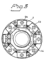
- Fig. 3 is a cross section of the same heater.
- thermoelectric elements 1 of alternately p and n character are arranged in rows and electrically connected in series by means of connector members 2.
- thermoelectric elements 1 which are made of e.g. lead and tellurium and a doping agent have a cylindrical shape and a length approximately corresponding to their diameter.
- Dependent on the intended use and the temperature interval other materials with known thermoelectric character may be chosen.
- said cylindrical elements 1 are not to be mounted standing between connector members but according to the present invention the latter have the shape of a plate on one side of which are made two essentially half-cylindrical parallel seats 3 for thermoelectric elements 1.
- Said plates 2 are intended to be mounted with said seats 3 facing each other on either side of a row of elements 1, opposed plates 2 being mutually off-set one seat width so as to form a continuous winding serial path for the generated current.
- the plates 2 are made planar on their side opposite to the seats 3 or otherwise adapted for lying against an intended hot surface.
- the opposed plates 2 are facing or engaging a suitable cooled surface.
- thermoelectric elements 1 are made similar to each other.
- thermoelectric generator unit As is further evident from Fig. 1, it is suggested according to the invention that two such rows of elements 1 with associated connector plates 2 are located in parallel and electrically connected to each other at one end of said pair of rows such that the two connection conduits to the thermoelectric generator unit will be situated adjacent each other at the opposite end of said pair of rows.
- said pair of element rows is arranged in one trough-like half-part 4a of a surrounding and sealingly closable housing 4.
- This half-part 4a is intended to face or engage with its bottom surface a hot surface such as a combustion tube of a parking heater while the other half-part 4b of the housing is made as a chamber for a suitable cooling fluid such as water.
- the housing 4 is made of stainless steel and in such case it is suitable that the same be welded all around the periferal edge between the half-parts 4a, 4b.
- an isolating layer 8 of mica or a ceramic material Between the rows of elements 1 with the associated connector plates 2 and the upper half-part 4b are arranged in order an electrically isolating layer 5 of plastic such as polyimide, a membrane metal plate 6 preferably of stainless steel and a pressure spring device 7 which here consists of two parallel pressure spring profiles 7a, 7b which are urged against the other half-part 4b of the housing.
- Said other or second half-part 4b of the housing preferably is made, such as is evident from Fig. 1, as a hollow chamber for a suitable cooling fluid such as water.
- a suitable cooling fluid such as water.
- suitable connecting pieces 9a, 9b for a cooling fluid circuitry are also illustrated.
- the electric connecting cables for the cassette-like thermoelectric generator unit suitably are arranged to extend from tubular pieces 10 on one end surface of the lower half-part 4a of the housing together with suitable sealing rings.
- the electric connecting cables for the cassette-like thermoelectric generator unit suitably are arranged to extend from tubular pieces 10 on one end surface of the lower half-part 4a of the housing together with suitable sealing rings.
- At the opposite small-end of said lower half-part 4a of the housing there are preferably mounted two further tubular pieces 11 adapted to provide for a filling of the trough-shaped space within said half-part 4a with a suitable isolating material such as perlite.
- said cavity is to be filled finally with some inert gas, preferably of low-heat conduction capacity or be subjected to vacuum in order to prevent an oxidation of the surfaces between the thermoelectric elements 1 and the connector plates 2, should the thermoelectric material be sensible to oxygene.
- said connector plates 2 preferably are made of copper and coated with nickel and as far as the plates at the cooled side are concerned, also with tin, if desired.
- a particular advantage of the above-stated construction with so-to-speak "lying" cylindrical elements 1 is that the expansion movements which occur when heating them to operating temperature of the unit will imply that the pressure force on the respective elements is increased and hence also the good engagement between the elements and the plates.
- the design according to the invention also provides for manufacturing advantages by allowing an easy maintaining of exact measures of the dimensions of both the element diameter and the connector plates. Furthermore, it is easy to adapt the interface areas to the desired electric effect, burner size etc.
- Figs. 2 and 3 has been illustrated an example of the use of cassette-like thermoelectric generator units according to the invention in a vehicle parking heater.
- Said heater thus comprises in its portion to the right of the drawing a fuel supply device 12 of a kind known per se with an ignition device 13 and a combustion tube 14 in which the combustion essentially takes place. The combustion gases then are discharged to the left of said drawing figure.
- Around the combustion tube 14 are in this case arranged eight cassette-like generator units 4 according to the invention.
- the units are electrically connected as desired and as known per se while the respective second casing halves 4b with their connection pieces are connected to some suitable system for supply of coolant, particularly water.
Landscapes
- Resistance Heating (AREA)
- Air-Conditioning For Vehicles (AREA)
- Instantaneous Water Boilers, Portable Hot-Water Supply Apparatuses, And Control Of Portable Hot-Water Supply Apparatuses (AREA)
Description
Claims (5)
- A thermoelectric generator unit comprising a plurality of thermoelectric elements (1) of alternately p and n character and electrically series connected by means of metal connector members (2), the elements having essentially cylindrical shape and the connector members being formed as plates (2), characterized in that on one side of said connector members are made two substantially semicylindrical and parallel seats (3) for thermoelectric elements (1), which connector members are adapted to be placed with said seats (3) facing each other to either side of a row of elements (1) with opposed plates mutually offset one seat width longitudinally of the row so as to form a continuous winding serial path for the generated current, the plates (2) on one side of the element row being adapted to face a heat source while the plates on the opposite side are facing a heat sink.
- A unit according to claim 1, characterized in that for securing a full and reliable electric contact at the interface between the connector plates (2) and the elements (1) at least the surfaces of the seats (3) on the plates (2) of copper are coated with nickel and, as to the plates at the cooled side, furthermore covered with tin.
- A unit according to claim 1 or 2, characterized in that the thermoelectric elements (1) with associated connector plates (2) are arranged in two parallel rows which are mutually electrically connected at one end of said element rows while the electric connections to a consumer are located at the opposite end of said element rows, said element rows with said associated connector plates being located in a trough-like half (4a) of a surrounding, sealingly closed housing (4), said half being adapted to engage a hot surface while the other half (4b) of the housing consists of a coolant chamber.
- A unit according to claim 3, characterized in that the housing (4) is made of stainless steel and preferably welded along its periferal edge between the halves (4a, 4b).
- A unit according to claim 3 or 4, characterized in that between the element rows with associated connector plates (2) and the other half (4b) of the housing (4) are located, in this order, starting from said element rows, an electrically isolating layer (5), a membrane metal sheet (6) preferably of stainless steel, and a pressure spring device (7) pressed against the inside of said other half (4b) of the housing.
Applications Claiming Priority (2)
| Application Number | Priority Date | Filing Date | Title |
|---|---|---|---|
| CA002252671A CA2252671A1 (en) | 1997-02-21 | 1997-02-21 | A thermoelectric generator unit |
| PCT/SE1997/000296 WO1998037587A1 (en) | 1997-02-21 | 1997-02-21 | A thermoelectric generator unit |
Publications (2)
| Publication Number | Publication Date |
|---|---|
| EP0907973A1 EP0907973A1 (en) | 1999-04-14 |
| EP0907973B1 true EP0907973B1 (en) | 2002-05-08 |
Family
ID=25680615
Family Applications (1)
| Application Number | Title | Priority Date | Filing Date |
|---|---|---|---|
| EP97916684A Expired - Lifetime EP0907973B1 (en) | 1997-02-21 | 1997-02-21 | A thermoelectric generator unit |
Country Status (4)
| Country | Link |
|---|---|
| US (1) | US6034318A (en) |
| EP (1) | EP0907973B1 (en) |
| CA (1) | CA2252671A1 (en) |
| WO (1) | WO1998037587A1 (en) |
Cited By (1)
| Publication number | Priority date | Publication date | Assignee | Title |
|---|---|---|---|---|
| DE202010003196U1 (en) | 2009-04-21 | 2010-07-29 | TEC COM GmbH Gesellschaft für Technik, Technologie & Vermarktung | Thermoelectric generator (TEG) |
Families Citing this family (20)
| Publication number | Priority date | Publication date | Assignee | Title |
|---|---|---|---|---|
| JP2946205B1 (en) * | 1997-12-25 | 1999-09-06 | セイコーインスツルメンツ株式会社 | Thermoelectric power generation unit and portable electronic device using the unit |
| US6312617B1 (en) | 1998-10-13 | 2001-11-06 | Board Of Trustees Operating Michigan State University | Conductive isostructural compounds |
| US6271459B1 (en) * | 2000-04-26 | 2001-08-07 | Wafermasters, Inc. | Heat management in wafer processing equipment using thermoelectric device |
| US6855882B2 (en) * | 2000-11-10 | 2005-02-15 | The Boc Group, Inc. | Cascaded inert gas purging system |
| US6459036B1 (en) | 2000-11-10 | 2002-10-01 | The Boc Group, Inc. | Cascaded inert gas purging of distributed or remote electronic devices through interconnected electrical cabling |
| US6580025B2 (en) | 2001-08-03 | 2003-06-17 | The Boeing Company | Apparatus and methods for thermoelectric heating and cooling |
| US7321591B2 (en) * | 2002-09-24 | 2008-01-22 | Efficient Networks, Inc. | Methods and systems for providing differentiated quality of service in a communications system |
| RU2230397C1 (en) * | 2002-10-28 | 2004-06-10 | Федеральное государственное унитарное предприятие Научно-производственное предприятие "Квант" | Thermoelectric battery |
| JP2004350479A (en) * | 2003-05-26 | 2004-12-09 | Hitachi Powdered Metals Co Ltd | Thermoelectric conversion power generation unit and tunnel type furnace equipped with this thermoelectric conversion power generation unit |
| US8481843B2 (en) * | 2003-09-12 | 2013-07-09 | Board Of Trustees Operating Michigan State University | Silver-containing p-type semiconductor |
| CN100452466C (en) * | 2003-09-12 | 2009-01-14 | 密歇根州州立大学托管委员会 | Thermoelectric material and its preparation method, thermoelectric element and method of generating electric current from thermal energy |
| JP4686171B2 (en) * | 2004-10-29 | 2011-05-18 | 株式会社東芝 | Thermal-electrical direct conversion device |
| US8384340B2 (en) * | 2007-06-26 | 2013-02-26 | The Coleman Company, Inc. | Electrical appliance that utilizes multiple power sources |
| US8519254B2 (en) * | 2008-04-08 | 2013-08-27 | The Boeing Company | Device and method for generating electrical power |
| US8230690B1 (en) * | 2008-05-20 | 2012-07-31 | Nader Salessi | Modular LED lamp |
| US10012375B1 (en) | 2008-05-20 | 2018-07-03 | Nader Salessi | Modular LED lamp |
| US9082928B2 (en) | 2010-12-09 | 2015-07-14 | Brian Isaac Ashkenazi | Next generation thermoelectric device designs and methods of using same |
| US20140083478A1 (en) * | 2011-04-19 | 2014-03-27 | Hokkaido Tokushushiryou Kabushikikaisha | Combustion Device, Combustion Method, and Electric Power-Generating Device and Electric Power-Generating Method Using Same |
| US20130327369A1 (en) * | 2012-06-07 | 2013-12-12 | Gentherm Incorporated | Thermoelectric system with mechanically compliant element |
| KR102398882B1 (en) * | 2017-05-30 | 2022-05-18 | 현대자동차주식회사 | Power generation module of air-conditioning system for vehicle |
Family Cites Families (9)
| Publication number | Priority date | Publication date | Assignee | Title |
|---|---|---|---|---|
| US3197342A (en) * | 1961-09-26 | 1965-07-27 | Jr Alton Bayne Neild | Arrangement of thermoelectric elements for improved generator efficiency |
| US3481794A (en) * | 1965-03-11 | 1969-12-02 | Westinghouse Electric Corp | Thermoelectric device with plastic strain inducing means |
| FR2519804A1 (en) * | 1982-01-14 | 1983-07-18 | Accumulateurs Fixes | ELECTROCHEMICAL GENERATOR BATTERY BOX |
| US4855810A (en) * | 1987-06-02 | 1989-08-08 | Gelb Allan S | Thermoelectric heat pump |
| US5015546A (en) * | 1989-06-12 | 1991-05-14 | Grid Systems Corporation | Battery compartment |
| US5228923A (en) * | 1991-12-13 | 1993-07-20 | Implemed, Inc. | Cylindrical thermoelectric cells |
| JP3263855B2 (en) * | 1992-03-06 | 2002-03-11 | ソニー株式会社 | battery pack |
| US5441576A (en) * | 1993-02-01 | 1995-08-15 | Bierschenk; James L. | Thermoelectric cooler |
| US5817188A (en) * | 1995-10-03 | 1998-10-06 | Melcor Corporation | Fabrication of thermoelectric modules and solder for such fabrication |
-
1997
- 1997-02-21 WO PCT/SE1997/000296 patent/WO1998037587A1/en not_active Ceased
- 1997-02-21 US US09/142,150 patent/US6034318A/en not_active Expired - Fee Related
- 1997-02-21 CA CA002252671A patent/CA2252671A1/en not_active Abandoned
- 1997-02-21 EP EP97916684A patent/EP0907973B1/en not_active Expired - Lifetime
Cited By (1)
| Publication number | Priority date | Publication date | Assignee | Title |
|---|---|---|---|---|
| DE202010003196U1 (en) | 2009-04-21 | 2010-07-29 | TEC COM GmbH Gesellschaft für Technik, Technologie & Vermarktung | Thermoelectric generator (TEG) |
Also Published As
| Publication number | Publication date |
|---|---|
| WO1998037587A1 (en) | 1998-08-27 |
| CA2252671A1 (en) | 1998-08-27 |
| EP0907973A1 (en) | 1999-04-14 |
| US6034318A (en) | 2000-03-07 |
Similar Documents
| Publication | Publication Date | Title |
|---|---|---|
| US6034318A (en) | Thermoelectric generator unit | |
| TW565877B (en) | Electric heater for heat-treatment furnace | |
| US11056735B2 (en) | Heat exchanger and battery unit structure for cooling thermally conductive batteries | |
| KR101168784B1 (en) | Electrochemical oxygen generator module assembly | |
| US6236810B1 (en) | Fluid temperature control device | |
| US6096966A (en) | Tubular thermoelectric module | |
| JP5785763B2 (en) | Heat transfer apparatus and manufacturing method | |
| EP0680585B1 (en) | Electric boiler for heat transfer liquid circulating in an open or closed system | |
| US20130152989A1 (en) | Thermoelectric generator having an integrated pretensioned mounting | |
| KR20180048260A (en) | Flexible thermoelectric module and thermoelectric appratus having the same | |
| US8378205B2 (en) | Thermoelectric heat exchanger | |
| JPH05640B2 (en) | ||
| EP1926155B1 (en) | Generator of electric energy based on the thermoelectric effect | |
| CN103628955B (en) | heat transfer unit | |
| FR2543275A1 (en) | Improvements applied to thermoelectric installations with thermal elements interposed between hot and cold conduits | |
| JP7786710B2 (en) | Heater case, heater device, and vehicle-mounted heater unit | |
| CN106206924B (en) | Thermoelectric power generation device for vehicle | |
| CA2613300A1 (en) | Heating apparatus comprising a thermoelectric device | |
| EP1352168A1 (en) | Rocket engine member and method for manufacturing a rocket engine member | |
| JP2002029249A (en) | Heat exchanger for heating | |
| JPH0412633Y2 (en) | ||
| JPH0412634Y2 (en) | ||
| US20250267770A1 (en) | Heating element and fluid heater and method for heating a fluid | |
| KR200261117Y1 (en) | heat pipe with heat transfer head | |
| FR2579055A1 (en) | ELECTRICAL HEATING DEVICE FOR GASEOUS FLUID |
Legal Events
| Date | Code | Title | Description |
|---|---|---|---|
| PUAI | Public reference made under article 153(3) epc to a published international application that has entered the european phase |
Free format text: ORIGINAL CODE: 0009012 |
|
| 17P | Request for examination filed |
Effective date: 19981005 |
|
| AK | Designated contracting states |
Kind code of ref document: A1 Designated state(s): AT BE CH DE DK FI FR GB IT LI NL SE |
|
| 17Q | First examination report despatched |
Effective date: 20010205 |
|
| GRAG | Despatch of communication of intention to grant |
Free format text: ORIGINAL CODE: EPIDOS AGRA |
|
| GRAG | Despatch of communication of intention to grant |
Free format text: ORIGINAL CODE: EPIDOS AGRA |
|
| GRAH | Despatch of communication of intention to grant a patent |
Free format text: ORIGINAL CODE: EPIDOS IGRA |
|
| REG | Reference to a national code |
Ref country code: GB Ref legal event code: IF02 |
|
| GRAH | Despatch of communication of intention to grant a patent |
Free format text: ORIGINAL CODE: EPIDOS IGRA |
|
| GRAA | (expected) grant |
Free format text: ORIGINAL CODE: 0009210 |
|
| AK | Designated contracting states |
Kind code of ref document: B1 Designated state(s): AT BE CH DE DK FI FR GB IT LI NL SE |
|
| PG25 | Lapsed in a contracting state [announced via postgrant information from national office to epo] |
Ref country code: NL Free format text: LAPSE BECAUSE OF FAILURE TO SUBMIT A TRANSLATION OF THE DESCRIPTION OR TO PAY THE FEE WITHIN THE PRESCRIBED TIME-LIMIT Effective date: 20020508 Ref country code: LI Free format text: LAPSE BECAUSE OF FAILURE TO SUBMIT A TRANSLATION OF THE DESCRIPTION OR TO PAY THE FEE WITHIN THE PRESCRIBED TIME-LIMIT Effective date: 20020508 Ref country code: IT Free format text: LAPSE BECAUSE OF FAILURE TO SUBMIT A TRANSLATION OF THE DESCRIPTION OR TO PAY THE FEE WITHIN THE PRESCRIBED TIME-LIMIT;WARNING: LAPSES OF ITALIAN PATENTS WITH EFFECTIVE DATE BEFORE 2007 MAY HAVE OCCURRED AT ANY TIME BEFORE 2007. THE CORRECT EFFECTIVE DATE MAY BE DIFFERENT FROM THE ONE RECORDED. Effective date: 20020508 Ref country code: FR Free format text: LAPSE BECAUSE OF FAILURE TO SUBMIT A TRANSLATION OF THE DESCRIPTION OR TO PAY THE FEE WITHIN THE PRESCRIBED TIME-LIMIT Effective date: 20020508 Ref country code: FI Free format text: LAPSE BECAUSE OF FAILURE TO SUBMIT A TRANSLATION OF THE DESCRIPTION OR TO PAY THE FEE WITHIN THE PRESCRIBED TIME-LIMIT Effective date: 20020508 Ref country code: CH Free format text: LAPSE BECAUSE OF FAILURE TO SUBMIT A TRANSLATION OF THE DESCRIPTION OR TO PAY THE FEE WITHIN THE PRESCRIBED TIME-LIMIT Effective date: 20020508 Ref country code: BE Free format text: LAPSE BECAUSE OF FAILURE TO SUBMIT A TRANSLATION OF THE DESCRIPTION OR TO PAY THE FEE WITHIN THE PRESCRIBED TIME-LIMIT Effective date: 20020508 Ref country code: AT Free format text: LAPSE BECAUSE OF FAILURE TO SUBMIT A TRANSLATION OF THE DESCRIPTION OR TO PAY THE FEE WITHIN THE PRESCRIBED TIME-LIMIT Effective date: 20020508 |
|
| REF | Corresponds to: |
Ref document number: 217449 Country of ref document: AT Date of ref document: 20020515 Kind code of ref document: T |
|
| REG | Reference to a national code |
Ref country code: CH Ref legal event code: EP |
|
| REF | Corresponds to: |
Ref document number: 69712482 Country of ref document: DE Date of ref document: 20020613 |
|
| PG25 | Lapsed in a contracting state [announced via postgrant information from national office to epo] |
Ref country code: DK Free format text: LAPSE BECAUSE OF FAILURE TO SUBMIT A TRANSLATION OF THE DESCRIPTION OR TO PAY THE FEE WITHIN THE PRESCRIBED TIME-LIMIT Effective date: 20020808 |
|
| NLV1 | Nl: lapsed or annulled due to failure to fulfill the requirements of art. 29p and 29m of the patents act | ||
| REG | Reference to a national code |
Ref country code: CH Ref legal event code: PL |
|
| EN | Fr: translation not filed | ||
| PG25 | Lapsed in a contracting state [announced via postgrant information from national office to epo] |
Ref country code: GB Free format text: LAPSE BECAUSE OF NON-PAYMENT OF DUE FEES Effective date: 20030221 |
|
| PG25 | Lapsed in a contracting state [announced via postgrant information from national office to epo] |
Ref country code: SE Free format text: LAPSE BECAUSE OF NON-PAYMENT OF DUE FEES Effective date: 20030222 |
|
| PLBE | No opposition filed within time limit |
Free format text: ORIGINAL CODE: 0009261 |
|
| STAA | Information on the status of an ep patent application or granted ep patent |
Free format text: STATUS: NO OPPOSITION FILED WITHIN TIME LIMIT |
|
| 26N | No opposition filed |
Effective date: 20030211 |
|
| PG25 | Lapsed in a contracting state [announced via postgrant information from national office to epo] |
Ref country code: DE Free format text: LAPSE BECAUSE OF NON-PAYMENT OF DUE FEES Effective date: 20030902 |
|
| EUG | Se: european patent has lapsed | ||
| GBPC | Gb: european patent ceased through non-payment of renewal fee |