EP0907680B1 - High density composite material - Google Patents
High density composite material Download PDFInfo
- Publication number
- EP0907680B1 EP0907680B1 EP97936036A EP97936036A EP0907680B1 EP 0907680 B1 EP0907680 B1 EP 0907680B1 EP 97936036 A EP97936036 A EP 97936036A EP 97936036 A EP97936036 A EP 97936036A EP 0907680 B1 EP0907680 B1 EP 0907680B1
- Authority
- EP
- European Patent Office
- Prior art keywords
- composition according
- nylon
- composite
- lead
- microns
- Prior art date
- Legal status (The legal status is an assumption and is not a legal conclusion. Google has not performed a legal analysis and makes no representation as to the accuracy of the status listed.)
- Expired - Lifetime
Links
Images







Classifications
-
- C—CHEMISTRY; METALLURGY
- C08—ORGANIC MACROMOLECULAR COMPOUNDS; THEIR PREPARATION OR CHEMICAL WORKING-UP; COMPOSITIONS BASED THEREON
- C08K—Use of inorganic or non-macromolecular organic substances as compounding ingredients
- C08K13/00—Use of mixtures of ingredients not covered by one single of the preceding main groups, each of these compounds being essential
- C08K13/04—Ingredients characterised by their shape and organic or inorganic ingredients
-
- C—CHEMISTRY; METALLURGY
- C22—METALLURGY; FERROUS OR NON-FERROUS ALLOYS; TREATMENT OF ALLOYS OR NON-FERROUS METALS
- C22C—ALLOYS
- C22C49/00—Alloys containing metallic or non-metallic fibres or filaments
- C22C49/02—Alloys containing metallic or non-metallic fibres or filaments characterised by the matrix material
- C22C49/10—Refractory metals
-
- A—HUMAN NECESSITIES
- A01—AGRICULTURE; FORESTRY; ANIMAL HUSBANDRY; HUNTING; TRAPPING; FISHING
- A01K—ANIMAL HUSBANDRY; AVICULTURE; APICULTURE; PISCICULTURE; FISHING; REARING OR BREEDING ANIMALS, NOT OTHERWISE PROVIDED FOR; NEW BREEDS OF ANIMALS
- A01K95/00—Sinkers for angling
- A01K95/005—Sinkers not containing lead
-
- C—CHEMISTRY; METALLURGY
- C08—ORGANIC MACROMOLECULAR COMPOUNDS; THEIR PREPARATION OR CHEMICAL WORKING-UP; COMPOSITIONS BASED THEREON
- C08K—Use of inorganic or non-macromolecular organic substances as compounding ingredients
- C08K3/00—Use of inorganic substances as compounding ingredients
- C08K3/02—Elements
- C08K3/08—Metals
-
- C—CHEMISTRY; METALLURGY
- C08—ORGANIC MACROMOLECULAR COMPOUNDS; THEIR PREPARATION OR CHEMICAL WORKING-UP; COMPOSITIONS BASED THEREON
- C08K—Use of inorganic or non-macromolecular organic substances as compounding ingredients
- C08K7/00—Use of ingredients characterised by shape
- C08K7/02—Fibres or whiskers
-
- C—CHEMISTRY; METALLURGY
- C22—METALLURGY; FERROUS OR NON-FERROUS ALLOYS; TREATMENT OF ALLOYS OR NON-FERROUS METALS
- C22C—ALLOYS
- C22C32/00—Non-ferrous alloys containing at least 5% by weight but less than 50% by weight of oxides, carbides, borides, nitrides, silicides or other metal compounds, e.g. oxynitrides, sulfides, whether added as such or formed in situ
- C22C32/0094—Non-ferrous alloys containing at least 5% by weight but less than 50% by weight of oxides, carbides, borides, nitrides, silicides or other metal compounds, e.g. oxynitrides, sulfides, whether added as such or formed in situ with organic materials as the main non-metallic constituent, e.g. resin
-
- C—CHEMISTRY; METALLURGY
- C22—METALLURGY; FERROUS OR NON-FERROUS ALLOYS; TREATMENT OF ALLOYS OR NON-FERROUS METALS
- C22C—ALLOYS
- C22C47/00—Making alloys containing metallic or non-metallic fibres or filaments
- C22C47/14—Making alloys containing metallic or non-metallic fibres or filaments by powder metallurgy, i.e. by processing mixtures of metal powder and fibres or filaments
-
- C—CHEMISTRY; METALLURGY
- C22—METALLURGY; FERROUS OR NON-FERROUS ALLOYS; TREATMENT OF ALLOYS OR NON-FERROUS METALS
- C22C—ALLOYS
- C22C49/00—Alloys containing metallic or non-metallic fibres or filaments
-
- C—CHEMISTRY; METALLURGY
- C22—METALLURGY; FERROUS OR NON-FERROUS ALLOYS; TREATMENT OF ALLOYS OR NON-FERROUS METALS
- C22C—ALLOYS
- C22C49/00—Alloys containing metallic or non-metallic fibres or filaments
- C22C49/14—Alloys containing metallic or non-metallic fibres or filaments characterised by the fibres or filaments
-
- F—MECHANICAL ENGINEERING; LIGHTING; HEATING; WEAPONS; BLASTING
- F42—AMMUNITION; BLASTING
- F42B—EXPLOSIVE CHARGES, e.g. FOR BLASTING, FIREWORKS, AMMUNITION
- F42B12/00—Projectiles, missiles or mines characterised by the warhead, the intended effect, or the material
- F42B12/72—Projectiles, missiles or mines characterised by the warhead, the intended effect, or the material characterised by the material
- F42B12/74—Projectiles, missiles or mines characterised by the warhead, the intended effect, or the material characterised by the material of the core or solid body
- F42B12/745—Projectiles, missiles or mines characterised by the warhead, the intended effect, or the material characterised by the material of the core or solid body the core being made of plastics; Compounds or blends of plastics and other materials, e.g. fillers
-
- G—PHYSICS
- G21—NUCLEAR PHYSICS; NUCLEAR ENGINEERING
- G21F—PROTECTION AGAINST X-RADIATION, GAMMA RADIATION, CORPUSCULAR RADIATION OR PARTICLE BOMBARDMENT; TREATING RADIOACTIVELY CONTAMINATED MATERIAL; DECONTAMINATION ARRANGEMENTS THEREFOR
- G21F1/00—Shielding characterised by the composition of the materials
- G21F1/02—Selection of uniform shielding materials
- G21F1/10—Organic substances; Dispersions in organic carriers
- G21F1/103—Dispersions in organic carriers
-
- Y—GENERAL TAGGING OF NEW TECHNOLOGICAL DEVELOPMENTS; GENERAL TAGGING OF CROSS-SECTIONAL TECHNOLOGIES SPANNING OVER SEVERAL SECTIONS OF THE IPC; TECHNICAL SUBJECTS COVERED BY FORMER USPC CROSS-REFERENCE ART COLLECTIONS [XRACs] AND DIGESTS
- Y10—TECHNICAL SUBJECTS COVERED BY FORMER USPC
- Y10T—TECHNICAL SUBJECTS COVERED BY FORMER US CLASSIFICATION
- Y10T428/00—Stock material or miscellaneous articles
- Y10T428/12—All metal or with adjacent metals
- Y10T428/12014—All metal or with adjacent metals having metal particles
Definitions
- the present invention relates generally to the fields of polymers and high density compositions. More particularly, it concerns materials that may act as a replacement for lead in applications requiring lead's high density, but where the toxic effects of lead are undesirable. Further, the high density composites of the present invention may be employed in any application where a high density material is required.
- a non-toxic, lead-free, environmentally safe, cost effective replacement projectile core material is required to enable firing ranges to remain open and to eliminate costly cleanup procedures.
- the density of the projectile should be close to that of a lead projectile for realistic performance simulation. Materials of a lower density decrease projectile range and penetration.
- the present invention in a general and overall sense, concerns a family of materials that may act as a replacement for lead in applications where the high density of lead is important, but where the toxicity of lead is undesirable.
- a high density composite for use in applications in which lead or any other high density material may be required.
- a high density composition of matter comprising a metal powder and a binder, wherein the method powder particle size is between 2 and 40 microns in diameter, wherein the metal powder is a blend with a distributor of different particle sizes, and wherein said metal is tungsten.
- a high density composition of matter comprising tungsten powder, a fiber and a binder material.
- the tungsten comprises between about 5% and about 95% of the composite.
- the tungsten comprises between about 10% and about 80% of the composite.
- the tungsten comprises between about 15% and about 70% of the composite.
- the tungsten comprises between about 25% and about 50% of the composite.
- the tungsten comprises between about 35% and about 40% of the composite.
- the tungsten may comprise any percentage between these figures, for example, about 5%, 6%, 7%, 8%, 9%, 12%, 14%, 16%, 20%, 21%, 22%, 23%, 24%, 26%, 28%, 30%, 32%, 34%, 36%, 38%, 42%, 44%, 46%, 48%, 52%, 54%, 56%, 58%, 60%, 62%, 64%, 66%, 68%, 72%, 74%, 76%, 78%, 82%, 84%, 86%, or 88% of the composite weight.
- the tungsten powder particle size is between about 2 and about 40 microns in diameter. In one embodiment the tungsten powder particle size is between about 4 and about 8 microns in diameter. In yet another embodiment, the tungsten powder particle size is between about 20 and about 40 microns diameter. Of course these are exemplary measurements and the powder may comprise a particle size of about 4, 5, 6, 7, 9, 10, 11, 12, 14, 16, 18, 21, 22, 23, 24, 25, 28, 30, 31, 32, 33, 34, 35, 36, 37, 38 or 39 microns in diameter. It is desirable to have tungsten powder comprised of particles having varying sizes of diameter.
- the fiber may comprise stainless steel, copper, aluminum, nylon, Kevlar®, Spectra®, nickel, glass or carbon.
- the fiber is stainless steel fiber.
- the fiber comprises between about 3% and about 30% of the composite weight. In other aspects the fiber comprises between about 10% and about 20% of the composite weight. In alternate embodiments, the fiber comprises between about 15% and about 18% of the composite weight.
- the fiber may comprise any percentage between these figures, for example, about 4%, 5%, 6%, 7%, 8%, 9%, 10%, 12%, 14%, 16%, 19%, 21%, 22%, 23%, 24%, 25%, 26%, 27%, 28% or 29% of the composite weight.
- the binder is a polymeric binder.
- the polymeric binder may be selected from the group consisting of cellulose, fluoro-polymer, ethylene inter-polymer alloy elastomer, ethylene vinyl acetate, ionomer, nylon, polythermide, polyester elastomer, polyester sulfone, polyphenyl amide, polypropylene, polyvinylidene fluoride or thermoset polyurea elastomer.
- the polymeric binder is Nylon 12® and polyester elastomer. In more specific embodiments the polymeric binder comprises between about 1% to about 30% weight ratio of the composite. In other embodiments, the polymeric binder is at a concentration of about 2% to about 20% weight ratio. In still further embodiments, the polymeric binder comprises between about 5% to about 15% weight ratio of the composite. In other embodiments, the polymeric binder comprises between about 8% to about 12% weight ratio of the composite.
- the high density composition may be utilized as a radiation shielding material.
- the radiation shielding material is a flexible shielding material.
- the composition may be utilized as modeling weights, fishing weights, flywheels, or projectiles.
- Lead from spent lead bullets represents a major source of environmental pollution as well as posing a potential health risk to both shooters and range personnel alike.
- Lead bullet residue left in the earthen berms of outdoor ranges can leach into the soil and contaminate water tables.
- Indoor ranges require extensive and expensive air filtration systems to operate safely as lead is introduced into the atmosphere as the projectile exits the barrel. Improved bullet traps are also required to permit lead collection and recycling. Outdoor ranges require constant soil remediation.
- the present invention provides compositions that may be used as lead substitutes, having a density similar to or greater than lead and being substantially less toxic to the user.
- the compositions of the present invention thus provide a new, relatively non-toxic, high performance replacement for metallic lead that can play a part in the ongoing transition from environmentally hazardous materials to ecologically acceptable ones.
- the compositions of the present will be useful not only in the manufacture of ammunitions but also in any applications requiring the use of a high density material.
- the materials are useful as weights, such as counterweights, fishing weights, wheel weights, flywheels or for use in model applications, such as in model railroading. Other similar applications include use as an acoustic dampening or vibration dampening material.
- high density material will find use in radiation shielding applications, for example, in radiotherapy and routine X-ray examinations and those applications requiring a radiation shielding compound that may be placed in small spaces, such as cracks.
- high density refers to a density that is near to or higher than the density of lead.
- compositions of the present invention may be used in the manufacture of practice ammunition for all types of rifles and pistols. If the lead-free projectiles are also frangible, they have applications when ricochet poses a danger to innocent parties. Applications for frangible non-toxic projectiles includes indoor/outdoor firing ranges; police and military training and qualification; commercial institutions; industrial installations; banks; prisons/jails; nuclear power plants; chemical processing plants; hospitals; and universities.
- the non-toxic projectile core technology of the present invention may be used to replace lead shotgun pellets, now prohibited for use in waterfowl hunting.
- the tungsten-based pellets will have similar performance to lead shot, unlike steel shot that is currently being used as a replacement for lead shot.
- Bismuth is also used, but this material is not as dense as lead, making it an undesirable material in lead shot replacement.
- Rifled slugs for shotguns and air rifle pellets may also be manufactured utilizing the non-toxic tungsten formulations according to the present invention.
- the compounds may be formed into sheets or blocks useful in radiation shielding applications.
- the high density materials of the present invention can be machined to form complex shields, housings or assemblies.
- Other radiation shielding applications include use in clothing worn by personnel exposed to radiation sources.
- Such dense, and non-toxic materials may further be formulated to be flexible and will find applications in protective clothing and other protective gear for medical and dental personnel, persons involved in the nuclear power or defense industries, and any other application where such clothing or apparel is worn.
- Lead is a soft, toxic and structurally weak metal and is therefore unsuitable for certain such applications.
- the material may be injection or compression molded into a variety of shapes. Injection molding fabrication using the material allows for high volume, low cost fabrication. Products utilizing the high density materials of the present invention may also be fabricated using thermoset and thermoplastic extrusion, thermoset and thermoplastic pultrusion, compression, centrifugal molding, rotational molding, blow molding, casting, calendering, liquid fill thermoset molding or filament winding to form a variety of shapes.
- the material of the present formulations comprises a tungsten powder as a high density component.
- Tungsten powder is relatively non-toxic and is suitable for commercial applications. Because solid metallic tungsten is a very hard material and melts at an extremely high temperature (approx. 3410°C, the highest melting point of all metals), the present formulations allows injection and compression molding and other previously mentioned methods, thus avoiding difficulties that may be encountered with working with pure tungsten.
- a novel aspect of the present formulations is the use of fibers to form a composite material comprising tungsten powder, polymeric binders, and fibers.
- the fibers may be stainless steel, or other metallic fibers such as copper, nickel, niobium, or titanium.
- non-metallic fibers such as glass fibers, Kevlar®, Spectra®, graphite, carbon, or boron, may be used to increase the tensile strength of the composition. It is possible to enhance the physical properties of the composition by adding various fibers, either singly or in combination with each other. For example, use of fibers softer than steel, such as glass, cellulose, cotton, nickel or copper fibers, may result in reduction of barrel wear in projectile applications.
- thermoplastic and thermoset materials as a polymeric binder.
- binder may be used to vary the physical properties of the composite, for example from very hard to soft and flexible.
- TPP means tungsten powder/polymeric binder composite materials.
- the binder may be a hot melt or thermosetting type of glue.
- the thermoset may comprise a single component whereas in other embodiments, the thermosets comprise a plurality of components.
- the properties of the composition may be varied as well by the use of tungsten powders of different particle sizes.
- the composition comprises a tungsten powder blend with a distribution of different particle sizes.
- Stainless steel fibers are added, for example, at about 5% by volume with the composition to improve tensile strength.
- the compositions of the present invention may be used as ionizing radiation shielding that is relatively non-toxic and easy to apply.
- tungsten powder is mixed with the bulk component of a two-part curing resin system, such as an epoxy resin.
- the resultant mixture having the viscosity of a caulking compound, is easily stored until ready for use.
- a catalyst is added and the mixture is thoroughly stirred.
- the material may then be applied to any surface, for example into cracks, and allowed to cure.
- the resulting cured material could, for example, then serve as a patch for radiation leaks in a radiation shielding system.
- the composition may be used as radiation shielding in clinical applications, for example to form shields for use in radiation therapy procedures.
- the formulations of the present invention are useful in making a lead-free projectile, which comprises, for example, a powder material that may be tungsten, tungsten carbide, ferrotungsten, and the like.
- the formulation also comprises a fiber material that may be, for example, stainless steel, copper, glass, zinc, and the like.
- the formulation comprises a binder material that may be a two-part curing resin, such as epoxy resin, polyurethane or polyester resin, or other polymer material.
- One-component thermosets are often cure initiated by air or moisture.
- methods are provided for molding articles of the present invention into a variety of shapes, including projectiles, shot, radiation shielding blocks, custom radiation shields with complex geometry, and the like. Also provided are methods of preparing the formulations into a putty-like consistency that may be applied into cracks or holes to block radiation passage.
- the compositions of the present invention and methods for making and using such compositions are described in further detail herein below.
- Table 1 presents a list of elemental metals that were considered as potential candidates for use as lead substitutes in high density compositions . From the list of metals with a specific gravity greater than lead, it is evident that tungsten meets the physical requirements of high density. Furthermore, tungsten has a low toxicity, making it an excellent metal of choice in lead substitutes and other high density materials.
- Table 1 Potential Candidate Base Metals and Alloying Metals Elemental Metal Specific Gravity Potential Base Metals Osmium 22.48 Iridium 22.42 Platinum 21.45 Rhenium 20.53 Tungsten 19.35 Gold 18.88 Tantalum 16.60 Hafnium 13.31 Rhodium 12.40 Ruthenium 12.30 Palladium 12.02 Thallium 11.85 Lead 11.43 Potential Alloying Metals Silver 10.50 Molybdenum 10.20 Bismuth 9.80 Copper 8.92 Cobalt 8.90 Nickel 8.90 Cadmium 8.64 Niobium 8.57 Iron 7.86
- tungsten as a lead substitute material is that, in addition to being comparatively non-toxic, it has a very high density (19.25 g/cc).
- Commercially available tungsten powders can therefore be mixed and pressed with softer and lighter non-toxic metals, such as tin or zinc, to generate lead substitute materials with a range of densities as high as, or even higher than, that of lead.
- copper was found to have a number of advantages as a useful material. It is relatively non-toxic and is widely accepted by the shooting community through its extensive use as a jacketing metal for lead projectiles. Solid copper has a reasonably high density of 8.96 g/cc, which is about 80% of that of lead.
- Copper in the metallic and powder form is not a severe pollutant. It is widely used in military stores. Nearly all small arms cartridge cases are made from brass (an alloy of copper and zinc). Its excellent lubricating and flow characteristics also make it the metal of choice for jacketing lead cores in small arms bullets. The price of copper is also sufficiently high to ensure that brass cartridge cases are always either reused or recovered for scrap. Expended copper bullet jackets also have value and can be recovered and recycled as scrap copper, further assisting reclamation of waste materials and protection of the environment. Copper alloys such as brass and bronze can also be used to make bullets. These alloys are harder than copper and need to be pressed at higher pressures and sintered at lower temperatures.
- Non-toxic metals such as zinc and tin are also potential candidates to replace lead but, being less dense than copper and tungsten, may suffer from problems arising from lower projectile mass such as compatibility with commercially available propellants, reliable cycling and feeding of weapons, realistic recoil energies and matching the trajectory of lead projectiles.
- the present invention circumvents this problem by providing methods of making composite materials that make the material more dense. More volatile metals than copper, such as tin and zinc, are also prone to forming ingestible vapors at the high temperatures generated during bullet impact on steel plates.
- Non-metallic components may be used in combination with the disclosed compositions to form a material of the requisite density in a relatively cost effective manner.
- Such non-metallic components may include mineral ores for example, hematite.
- the present inventors have added metal fibers at a low volume fraction.
- the inventors performed a survey to identify suitable metal fibers for use in a projectile core application.
- the metal fibers need to possess high strength, high specific gravity and have a low cost.
- the survey revealed that the most cost effective metal fibers with high strength and specific gravity are chopped stainless steel fibers.
- Stainless steel fibers are readily available and are currently being added to injection moldable polymer resins at up to a 30% volume ratio for electromagnetic shielding applications.
- Fiber made from 316 stainless steel with a length of 0.125 inches, a thickness of 75 microns, a specific gravity of 8.0 was selected as a representative tungsten powder/polymeric binder material additive.
- any of the metals listed in Table 1, may further be formulated into fibers for use in the present invention.
- a "binder” is a material that is used to provide cohesion between the high density metal powder and the fibers such that the integrity of the metal and the fiber is maintained.
- Table 2 presents a summary of selected properties for polymeric binders considered for mixing with tungsten powder.
- the selection criteria used to form this list of potential polymeric binder materials included good ductility (high elongation values), high strength, high modulus, high melting temperatures, high impact strength, low water absorption and low cost.
- the Nylon 6® and Nylon 6,6® resins were found to have high water absorption values.
- the polyethersulfone and polyphthalamide had low elongation values.
- the cellulose resin was retained even though it also has low elongation because it is a biodegradable projectile core material. After consulting with U.S. Army ARDEC engineering personnel, it was determined that all of these candidate materials should be chemically compatible with the cartridge propellants.
- thermoset elastomer All of the selected candidate polymer resins are injection molding grades except for the thermoset elastomer.
- the polyurea thermoset elastomer is a Texas Research Institute/Austin MDI/Polamine 1000 formulation.
- the Polamine 1000 polyurea elastomer formulation is prepared by mixing 38.02g Dow 2.143L (a modified diphenylmethane diisocyanate) and 150g Polamine 1000 (an amine terminated polytetramethylene ether made by Air Products) with Teledyne C-8 tungsten powder for a final product density of 10.33g/cc. This material is referred to hereinafter as "TRI/Austin MDI/Polamine 1000 formulation". Table 2.
- the material testing consisted of performing flexural three point bend tests on compression molded tungsten powder/polymeric binder flexural test bars and performing tensile tests on injection molded tungsten powder (and stainless steel fiber) polymeric binder tensile test bars.
- the flexural testing was used to screen the large number of candidate polymer mixtures and to select several optimal materials for injection molding.
- the tensile testing was performed to compare the material properties of each candidate injection molded composite mixture and lead.
- thermoset polymeric binder (TRI/Austin MDI/Polamine 1000 formulation) was mixed with tungsten powder in a standard rotary mixer using a 50% volume ratio.
- the tungsten powder thermoset polymeric binder mixture was placed into a flat plate compression mold. The mold was put into a hydraulic compression molding machine and was allowed to cure overnight at room temperature under clamping pressure. Flexural test bars were punched from the flat plate using a flexural test bar stamping die. All of the flexural test bars had the following dimensions; 6.35 cm (2.5 inch) length by 1.27 cm (0.5 inch) width by 0.3175 cm (0.125 inch) thickness. Table 3 provides the average measured specific gravity for each of the polymeric binders used.
- the flexural test bars had a specific gravity ranging from 10.00 to 10.63.
- Table 3 Specific Gravity of Compression Molded Tungsten powder/polymeric binder Flexural Test Bars Polymeric binder Specific Gravity Biodegradable Cellulose (Planet Polymers PT-C300ZT) 10.02 ECTFE Flouropolymer (Ausimont Halar 5001LC) 10.63 Ethylene Interpolymer Alloy Elastomer (DuPont Alcryn 2070NC) 10.15 Ethylene - Vinyl Acetate Elastomer (DuPont Elvax 360) 10.48 Ionomer (DuPont Surlyn 8220) 10.00 Nylon 11® (Atochem BMFO) 10.10 Nylon 12® (EMS Grilamide L20GHS) 10.08 Polytherimide (G.E.
- the elastomeric polymeric binders (ALCRYN 2070NC, ELVAX 360, TEXIN 480A and the polyurea thermoset) showed the most ductile behavior having the lowest flexural strength and modulus, and the highest flexural displacement.
- the high melt temperature polyetherimide (ULTEM 1000) mixture had the highest flexural strength and modulus but exhibited a brittle behavior with a low flexural displacement.
- the Nylon 12® GRILAMIDE L20GHS
- Nylon 12® GRILAMIDE L20GHS
- polyester thermoplastic elastomer TEXIN 480A
- Tungsten powder/polymeric binder mixtures using the Nylon 12® (GRILAMMIDE L20GHS) and polyester thermoplastic elastomer (TEXIN 480A) resins were prepared in a Brabender mixer.
- 700 cc mixtures were prepared for each polymeric binder with a tungsten powder volume ratio of 54%. The tungsten powder had evenly distributed particle sizes ranging from 2 to 20 microns.
- An additional 700 cc mixture was also prepared for each polymeric binder by adding stainless steel fibers at a 10% volume ratio to the Nylon 12® tungsten powder/polymeric binder material. Each mixture was removed from the Brabender mixer and ground into particles using a grinder. Table 4 shows the volume and weight ratios for each mixture.
- ASTM D638 Type V "dogbone" tensile test bars 6.35 cm (2.5 inch) length by 0.3175 cm (0.125 inch) width by 0.1524 cm (0.06 inch) thickness) were injection molded from each mixture using a Master Precision Mold Test Specimen Four Cavity mold.
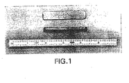
- Figure 12 shows a picture of the injection molded composite material tensile test bars.
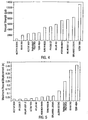
- Figure 8 compares the tensile strength of the composite projectile core materials to lead.
- the Nylon 12®/tungsten powder/stainless steel fiber composite had the highest tensile strength of the three composite materials.
- the addition of stainless steel fibers increased the strength of the Nylon 12® tungsten powder composite approximately 4.5% from 46670 to 48774 kPa (6,769 to 7,074 psi.)
- Both of the Nylon 12® composite materials had much higher tensile strengths than lead, while the polyester elastomer composite was approximately one third of that of lead.
- Figure 9 compares the elongation at break values. None of the composite materials showed elongation values as high as the 50% value for tead.
- the polyester elastomer composite showed the most elongation of the composite showed the most elongation of the composite materials tested with a value of 5.9%.
- Figure 10 presents the tensile modulus results for the composite materials relative to lead.
- the addition of stainless steel fiber provided an 8.6% improvement in tensile modulus from 6715 to 7295 MPa (974 to 1,058 ksi) for the Nylon 12® composite material.
- the polyester elastomer had an extremely low modulus of 217 MPa (31.5 ksi) compared to the 16134 MPa (2,340 ksi) modulus of lead.
- the tensile test results show that Nylon 12® composite projectile possess a superior tensile strength and have a reasonably high tensile modulus compared to lead, but are much less ductile than lead.
- the addition of stainless steel fibers in the Nylon 12® composite material substantially increases the tensile strength and modulus with negligible reduction in ductility.
- the polyester elastomer was the most ductile of the composite materials, but had the lowest tensile strength and modulus.
- TPP binder composites with specific gravities in the range of 10 to 11 may be formulated to produce a variation in physical properties, depending on the type of polymeric binder employed. Moreover, the incorporation of fibers, such as stainless steel fibers, into the tungsten powder/polymeric binder composite materials demonstrates an improvement in physical properties of the material.
- Over 150 7.62 mm projectile cores with specific gravities ranging from 10.2 to 11.0 were injection molded using tungsten powder and stainless steel fibers and mixed in a Nylon 12® and polyester elastomer polymeric binder.
- the polymeric binders such as Nylon 12®, polyester elastomer, and polyetherimide were compounded with tungsten powder in the ranges of 2 to 4 microns, 4 to 8 microns and 20 to 40 microns, followed by physical evaluation of composite. Larger particle sizes have less total surface area than smaller particle sizes for a given mass of tungsten powder, therefore it is possible to add more of the larger particle size powder with the polymeric binder to produce a more dense TPP composite.
- fibers such as stainless steel fibers, were added to the composite. Fibers may be added in volume ratios such as 10, 20, and 30%. The effect of fiber volume on the physical properties of the TPP composite is evaluated.
- Specimens may be injection molded from each of the TPP composite materials compounded as above. Molding of tensile and impact bars may be accomplished using, for example, the Master Precision Mold Test Specimen Four Cavity Model injection mold. See FIG. 11. The mold produces the following test specimens:
- FIG. 12 shows an injection molded TPP composite tensile bar. It is contemplated that the methods of the present invention will be utilized to mold ASTM D638 Type I "dogbone" tensile bars for tensile testing and impact test bars will be molded to Izod impact testing.
- Materials properties tests are performed on each selected candidate TPP composite material to evaluate the physical behavior of the material and to compare the material properties of the composite material to lead. These tests were used to screen TPP composite materials demonstrating inadequate physical properties performance, such as low specific gravity, low ductility, low impact strength or low tensile strength.
- the physical properties testing consists of determining the specific gravity, performing tensile and Izod impact tests, and thermal expansion tests on each of the candidate TPP composite materials. The average specific gravity of each material is calculated by measuring the mass and volume of the tensile and impact bars injection molded as above.
- FIG. 7 shows a picture of a fractured TPP composite tensile test bar in the Instron testing machine. The average tensile strength, elongation at break and modulus were calculated for each material.
- FIGS. 8-10 present representative tensile test results that may be used to assess the tensile properties of each material and compare these tensile properties to lead.
- the coefficient of thermal expansion is determined for each candidate TPP composite material.
- the thermal expansion is measured by attaching strain gauges to impact test bars.
- the strain gauges are oriented parallel and perpendicular to the long axis of the bar to measure the thermal expansion in the flow and cross flow mold directions.
- the testing is performed in a temperature controlled environmental chamber and thermocouples are attached to the bar to accurately measure temperature.
- An automated data acquisition system records both the temperature and strain in real time during the test.
- the TPP composite thermal expansion results are compared to the coefficient of thermal expansion for the copper jacket material to predict thermal stresses that would be applied to the TPP composite projectile core by the copper jacket due to differential thermal expansion.
- the coefficient of thermal expansion for copper is about 16.56 parts per million degree C (9.2 parts per million degree F) 4.59 (2.55) for tungsten and 126 (70) for Nylon 12®.
- the estimated coefficient of thermal expansion for a tungsten powder/Nylon 12® composite with a specific gravity of 11.0 would be about 60.48 parts per million degree C (33.6 parts per million degree F.)
- One method of making copper jacketed injection molded metal powder polymeric binder composite projectile cores is to place the copper jacket into the injection mold and inject the metal powder polymeric binder composite material into the jacket cavity.
- the second and preferred method is to injection mold the tungsten powder/polymeric binder projectile core, insert the molded projectile core into the jacket, and cold form both the core and jacket into the desired bullet geometry.
- FIGS. 29 and 30 are drawings of the 7.62 mm projectile core injection mold. About 50 projectile cores were injection molded from each of the metal powder (and stainless steel fibers) polymeric binder composite mixtures shown in Table 4.
- FIG. 13 shows a picture of an injection molded projectile core, a lead projectile core, and a copper jacketed lead projectile core.
- the single cavity 7.62 mm projectile core injection mold may be modified into a multi-cavity mold to allow for more economical production of larger quantities of TPP composite projectile cores. It is also recognized that high volume production projectile core injection molds may be utilized with the formulations of the present invention. Such molds, for example, may contain about 32 cavities.
- a copper jacket is cold formed onto the core. While this method may be suitable for the present compositions, another method is to heat the projectile core above room temperature but below the meld temperature of the polymeric binder (approximately 100 to 150 degrees C) prior to insertion of the core onto the copper jacket. This in effect would change the cold forming process into a hot (or warm) forming process. Because the polymeric binders are thermoplastics they will become much more ductile at the warmer temperature allowing for improved forming of the projectile core into the final desired bullet shape. The second method is to change the shape of the injection molded core to more closely resemble the final copper jacketed bullet shape. This allows the molded projectile core to be cold formed into the final copper jacketed bulled shape with less deformation of the TPP composite material.
- Projectile cores suitable for the present invention include but are not limited to, for example, 5.56mm, 9mm, and 12.7 mm (.50) caliber ammunition. Also suitable are 7.62 mm and 11.43 mm (.45) caliber.
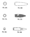
- FIGS. 26-28 are design drawings for 7.62 mm ammunition, and are used in design studies. Such design studies identify appropriate TPP composite materials to use for each type of lead projectile core replacement.
- Table 5 shows the average projectile core weight and specific gravity, and Table 6 shows the average dimensional measurements for the TPP composite projectile cores. Table 5 Average Weight and Specific Gravity of Injection Molded Composite Projectile Cores Composite Projectile Core Material Average. Projectile Core Weight (g) Average.
- Compression tests are performed by placing the projectile core on a flat plate in an Instron testing machine oriented vertically with the tip of the projectile core up.
- a second flat plate attached to the crosshead of the machine allows the projectile core to be compressed between the two plates by the testing machine.
- the projectile core is tested to failure.
- a lead projectile core is also compression tested for comparison to the TPP composite cores, allowing a comparison between compressive strength, and modulus of each core.
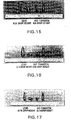
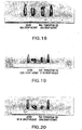
- FIG. 14 shows a vertical drop compressive impact test that provides a qualitative assessment of impact resistance for each of the TPP composite material projectile cores and lead projectile cores.
- the projectile core 1 is placed in a stand 2 mounted on a concrete floor 3.
- An impact mass 4 of 7.48 kg (16.5 lb) is released from calibrated height positions 5 of 15.24, 30.48 and 45.72 cm (6, 12, and 18 inches).
- FIGS 15-23 show side-by-side comparison pictures of each candidate TPP composite material compared to lead. A visual comparison material showed the greatest impact resistance of the composite materials tested. This qualitative assessment indicates that the addition of stainless steel fibers substantially increases the impact resistance of the Nylon 12® tungsten powder composite materials.
- the Nylon 12® composite material with and without stainless steel fibers appear to perform as well or better than the lead projectile cores (retain the same or more of their original shape) at each drop height.
- the lead projectile cores show more deformation than the Nylon 12® composite cores, but the Nylon 12® cores tend to shed material at higher impact levels.
- the polyester elastomer projectile cores show about the same deformation as the lead cores but fragment at all drop heights.
- Ballistic testing of projectile cores is accomplished by testing the velocity and pressure (ANSI/SAAMI method) from test barrels. Chamber pressure and velocity measurements are made simultaneously, and individual values, mean values, extreme variation of individual values, and standard deviation are measured. Also measured is accuracy from test barrels, bullet integrity and fouling, function and casualty of ammunition, penetration, and temperature stability.
- All three of the composite materials showed excellent dimensional stability after injection molding. The diameter and length measurements were consistent with only a 1 to 2 mils difference between individual projectile cores. Each of the three composite materials had similar diameter and length measurements with the polyester elastomer having slightly larger dimensions than the Nylon 12® composites. All of the materials showed mold shrinkage having smaller dimensions than the design drawing specifications of 0.6223 cm (0.245 inches) in diameter and 2.624 cm (1.033 inches) in length. This indicates that the projectile core injection mold will have to be adjusted accordingly once a final composite material is selected. The mass and volume of the injection molded projectile cores were measured and the specific gravity of each composite materials was determined. Table 5 presents the weight and specific gravity of the candidate metal powder (and fiber) polymeric binder composite projectile cores.
- thermoplastic injection moldable and two thermosetting polymers were successfully mixed with tungsten powder producing projectile core composite materials with specific gravities ranging from 10.0 to 10.63.
- a wide range in physical properties was achieved depending on the type of polymeric binder system employed.
- the tungsten powder/polymeric binder composite materials showed physical behavior ranging from brittle to highly ductile.
- the flexural strength of the composite materials ranged from 3509 to 89563 kPa (509 to 12,990 psi), the maximum flexural displacement ranged from 0.051 to 1.168 cm (0.02 to 0.46 inches), and the flexural modulus ranged from 111.7 to 17451 MPa (16.2 to 2,531 ksi).
- Stainless steel fibers were successfully added to two tungsten powder/polymeric binder composite projectile core materials to improve physical properties and reduce cost. Both tensile bars and projectile cores were successfully injection molded using 46% by volume tungsten powder and 10% by volume stainless steel fibers in a polymeric binder.
- Both tungsten powder/polymeric binder composites and tungsten powder and stainless steel fiber polymeric binder composite materials can be easily mixed together and injection molded using standard mixing and molding equipment. No mixing problems were encountered with tungsten powder volume ratios as high at 54% and a stainless steel fiber ratio of 10%. Visual examination of the molded projectile cores showed excellent surface finish and no void or porosity problems were identified. Although no formal procedure was used to measure the balance of the projectile cores, a visual examination of the sectioned cores showed the appearance of an even distribution of metal powder and fibers in the polymer matrix.
- Two composite materials were developed for use in projectile assembly as illustrations of the uses of the compositions of the present invention. These materials included a tungsten/Nylon 12® composite and a tungsten/Nylon 12®/stainless steel composite. Stainless steel fibers (0.3175 cm (0.125”) long, 75 micron diameter) were used in the second composite to provide a 4% increase in flexural strength and 8% increase in tensile modulus.
- the process for manufacturing the materials consists of mixing each component in a Brabender-type mixer and then grinding the materials into particles. The tungsten/nylon composite is ground much finer than the stainless steel composite which is left as a more coarse material so as not to damage the steel fibers.
- the cores manufactured by TRI demonstrated excellent uniformity in terms of core length and diameter. However, there was significant amount of variation noted in the core weight. Average weights of both composites were below the 32 ⁇ 0.3 grain requirement. The tungsten-Nylon 12® composite, although close to the requirement, averaged 31.3 grains while the tungsten-Nylon 12®-stainless steel composite was significantly lighter, averaging 27.5 grains. Part of the reason for the low weight was the core overall length, which, although consistent, was approximately 0.132 cm (0.052 in) less than the recommended length due to post mold shrinkage. If the stainless steel composite cores were molded to the recommended length the corresponding weight would be 30.8 grains, much closer to meeting the requirement.
- Table 8 shows a comparison of the average measured weights and dimensions for each sample as compared to the dimensions shown on the core drawing.
- the Score Factor in the far right column is a cumulative total of the percentage difference between the average sample dimension and the corresponding drawing (requirement) dimension. Therefore, the lowest scoring factoring represents the closest similarity to the desired weight and dimensions.
- Table 8 Core Dimensional Characteristics MATERIAL *DIA.
- TRI#1 tungsten-nylon composite
- the TRI#2 sample the tungsten-nylon-stainless steel composite, was then used. Again, no adjustments were made to the BAM and no feed or assembly problems were encountered. Bullets met all dimensional requirements, however, the weight of the TRI#2 samples were approximately 3-4 grains below the requirement.
- the TRI#1 samples showed a higher degree of weight variation. With the TRI#1, 7% of the inspected parts weighed 60.2 grains, 0.1 grains below the minimum weight while the TRI #2 sample had only 5% within requirements. The remainder of the latter sample fell below the minimum weight, averaging 58.2 grains which was expected due to the use of regrind material during the molding process.
- Cartridges made from lead and each of the composites TRI#1 and TRI#2 were then subjected to a series of tests to assess the interior, exterior and terminal ballistic performance of each material candidate.
- the current 5.56 mm M855 cartridge was used as the baseline (control or reference) for assessing performance.
- Testing was conducted at three locations: Lake City Army Ammunition Plant, Naval Surface Warfare Center, Crane, and the Armament Technology Facility (ATF), Picatinny Arsenal. Testing conducted by LCAAP included Electronic Pressure, Velocity and Action Time (EPVAT) as well as dispersion at a 549 m (600 yard) range.
- EVAT Electronic Pressure, Velocity and Action Time
- EPVAT testing was used to identify the pressures the projectiles were subjected to when launched from a gun tube as well as the corresponding velocities achieved while dispersion testing provided a true indication of the performance of the rounds in terms of stability during flight and uniformity during manufacture.
- Results of the EPVAT test are shown in Table 12.
- Data obtained from this test included casemouth pressure, port pressure (the pressure at a mid-point in the barrel comparable to the gas port location on automatic weapons), velocity at 23.8 m (78 ft) from the muzzle, and action time which is the time from primer indent to when peak port pressure is obtained.
- Both TRI composites met all the requirements for pressure, velocity and action time at each of the three temperatures. It is also interesting to note that the TRI#2, which had the largest weight variation, demonstrated a velocity variation similar to that obtained with the control sample.
- a rolling witness paper which was scrolled after each shot, was placed 7.62 m (25 ft) in front of the weapon in order to record any instances of projectile break-up or yaw.
- 7.62 m 25 ft
- the thermal expansion and contraction of the materials at the extreme temperatures is negligible.
- the TRI composites showed no evidence of projectile/core break-up.
- Dispersion tests were then conducted using a M700 receiver and two accuracy barrels mounted in a v-slide. Each of the barrels had approximately 1,250 rounds fired prior to this test and were qualified with M855 reference ammunition. Two record targets consisting of 10 rounds each were fired from each barrel at ambient, hot [51.7°C(+125°F)], and cold [-53.9°C (-65°F)] temperatures with both TRI samples and the control sample. Ammunition was temperature conditioned for 4 hours prior to firing. Weather conditions were clear, approximately 11.7°C (53°F) with 1.3 to 3.6 m/s (3 to 8 mile per hour) winds. After qualifying the barrels, each of the four test samples were fired, followed by the control sample. This procedure was followed at each temperature.
- the score factors shown in these tables were determined by calculating the percent difference between the best performer and each other sample. In this case, the best performer was whichever sample showed the smallest dispersion in the category being evaluated. These categories included mean radius, horizontal standard deviation, vertical standard deviation, and extreme spread at each of the three temperatures. Results obtained at each temperature were then combined in order to identify the best overall performer. This was accomplished by adding the score factors calculated at each temperature (Table 19). Each sample was then ranked according to this final score with the lowest score receiving the highest ranking. It is interesting to note that both TRI samples which showed the largest dimensional variation during manufacture, also exceeded the performance of the standard M855 cartridges.
- the Naval Surface Warfare Center, Crane, IN conducted testing to assess the terminal performance of the cartridges incorporating TRI#1 and TRI#2 composites against simulated hard and soft targets. Data obtained from these tests was used to identify any shortfalls or improvements of the candidate cartridges as compared to the standard M855 cartridge.
- Soft target testing against 20% ballistic gelatin blocks 10 positioned at 10 meters from the weapon was conducted with each sample. Prior to testing, blocks were temperature conditioned to 10°C (50°F) for 36 hours and calibrated using the BB penetration criteria. This criteria states that a 4.50 mm (.177) caliber BB at a velocity of 266 ⁇ 6.7 m/s (595 ⁇ 15 fps) should penetrate the block to a depth of 38.1 ⁇ 6.35 mm (1.5 ⁇ .25 in).
- the weapon used for the test was a M16A2-E3 rifle which was shoulder fired. Velocity for each round fired was recorded at a distance of 4.57 m (15 ft) from the muzzle.
- Results showed the TRI#1 cartridges most closely matched the performance of the reference M855 cartridge in terms of cavity dimensions while the TRI#2 provided the closest match in terms of penetration depth.
- the TRI#1 and TRI#2 samples averaged 34.0 cm (13.4 in) and 31.0 cm (12.2 in) of penetration, respectively. Score factors were determined by totaling the average values for penetration depth and cavity dimensions and then calculating the percent difference between the largest total and totals for the remaining samples. This method assumes that the largest cavity dimensions indicate the best performance.
- Table 20 10 10 Meter Ballistic Gelatin Test Results Temporary Cavity Sample Rd No. Vel @ 4.57 m (15Ft) [m/s(fps)] Penetration Depth [cm (in.)] Max. Dia. [cm (in.)] Max.
- Score Factor TRI#1 1 939.1(3081) 35.3(13.9) 10.7(4.2) 20.3(8.0) 2 944.3(3098) 39.1(15.4) 11.2(4.4) 20.8(8.2) 3 938.9(3080) 36.8(14.5) 12.7(5.0) 14.0(5.5) 4 937.0(3074) 24.9(9.8) 13.2(5.2) 18.5(7.3) AVG 939.7(3083) 34.0(13.4) 11.9(4.7) 18.3(7.2) 1.19 TRI#2 1 926.9(3041) 33.0(13.0) 14.7(5.8) 19.8(7.8) 2 941.8(3090) 27.4(10.8) 13.7(5.4) 17.8(7.0) 3 932.4(3059) 31.8(12.5) 15.2(6.0) 22.1(8.7) 4 922.0(3025) 31.5(12.4) 15.7(6.2) 21.3(8.4) AVG: 930.9(305
- the TRI#1 samples achieved the greatest penetration depth while the cavities produced by the lead projectiles were slightly larger than the cavities produced with the other samples. It was also noted that one or two projectiles of each type fragmented upon impact with the glass. Cavities in the gelatin block were then based on the impact of these fragments.
- the TRI#2 sample had no CPs after four rounds fired.
- the TRI#1 sample achieved CPs for 6 rounds fired.
- the target plate was then moved back to 365 meters where the TRI#1 sample achieved 2 CPs for 6 rounds fired.
- the R50 range for each sample was determined.
- the TRI#2 and M855 cartridges each achieved an R50 range of 355 meters.
- the TRI#1 sample had the greatest R50, 363 meters. Muzzle velocity and V50 velocity, which is the impact velocity at the R50 range were also determined for each sample. Results of this test are shown below in Table 25.
- the score factors in the right side column were determined by calculating the percentage difference between the farthest R50 range (363 meters for the TRI#1 sample) and the R50 range for each other sample. As in the previous tables, the lower sore factor indicates better performance.
- Table 25 R50 vs. 12.7 mm Aluminum Plate Sample Muzzle Velocity [m/s (fps)] V50 Velocity [m/s (fps)] R50 Range (m) Score Factor TRI#1 928.7(3047) 598.3(1963) 363 1.00 TRI#2 9315(3056) 582.2(1910) 355. 1.02 Lead 932.7(3060) 610.8(2004) 355 1.02
- the set-up and equipment used for this test was the same as used for the previous test against the aluminum plate.
- the target plate was originally positioned at 600 meters from the weapon. Cartridges were then loaded and fired single shot. After each shot the target was inspected and the shot was determined to be valid or invalid. To be considered valid, a shot had to hit the plate not less than 2.54 cm (1 in) from the nearest hole, support, or edge of the plate. For each valid shot, the penetration, either full or partial was assessed. This procedure was repeated with each sample. After firing the test rounds, the target range was increased until the R50 range was established. Again, the score factors in the right side column were determined by calculating the percentage difference between the farthest R50 range and the R50 range for each other sample.
- the objective of this test was to compare the penetration performance of the test cartridges when fired into concrete blocks positioned at a range of 50 meters from the weapon.
- Targets consisted of regular 2-core concrete blocks rigidly mounted on top of a target platform. Blocks were held in place with a 0.635 cm (1/4") steel bracket positioned over the block and bolted to the platform.
- Six valid shots (2 per block) were fired with each type of cartridge. A shot was considered valid if it impacted a core not previously shot and the bullet was more than 3.81 cm (1.5 in) from the edge or center of the block.
- Each of the test cartridge samples completely penetrated the front wall of the target. The only projectiles to completely penetrate the block were the standard lead projectile; 2 of the 6 rounds fired achieved complete penetration. On average TRI#2 sample produced the least damage.
- This test was conducted to obtain information on the condition of the projectiles after being fired into a simulated target berm.
- the target berm in this case consisted of sandbags which were positioned 100 meters from the gunner.
- a witness panel was placed behind the sand bags to determine if the projectiles completely penetrated the sand bags. After firing 15 to 20 rounds into the berm, the sand was sifted through a screen and the projectile fragments were recovered and photographed. New sandbags were used for each sample tested.
- the TRI#1 and TRI#2 cores did not demonstrate the same high degree of fragmentation after impact. A larger percentage of these cores were recovered both within the jackets and in pieces separate from the jackets. The TRI#2 cores demonstrated the least amount of frangibility of all the samples. Several samples of these cartridges were recovered while reasonably still intact.
- Lead projectile fragments consisted primarily of jacket pieces and lead chunks which most closely resembled the TRI#1 fragments.
- the table below shows the average weight of the seven largest recovered core fragments of each type.
- the TRI#2 projectiles on average, retained the largest mass of all the samples tested. Although this test was conducted with a limited number of rounds under tightly controlled conditions, this may be an indication of how easily recoverable the materials will be for recycling purposes.
- a mass comparison of the recovered projectile fragments is shown in Table 28. Table 28 Average Mass of Recovered Projectile Fragments (Grains) Sample Average Mass of Recovered Fragments (Grains) Score Factor TRI#1 29.4 1.68 TRI#2 49.4 1.00 Lead 37.9 1.31
- Toxic fumes testing was conducted at the ARDEC Armament Technology Facility. This test assessed the gaseous and particulate emissions from the cartridges when fired.
- an M16A2 rifle was mounted in a hard stand enclosed in a sealed chamber. Five firing trials were conducted using each of the five cartridge samples. For each trial, 30 rounds of ammunition were loaded into the magazine and fired into water traps in ten 3-round bursts with 3 - 5 seconds between bursts. Gas and metal concentrations were monitored during the firing and for a 30-minute period after the firing of each trial was completed. Sampling points were located 15.2 cm (6 in.) to the left and right of the buttstock as well as directly behind the buttstock. These locations, which are illustrated in FIG. 32, were chosen to simulate the position of the gunner's head while firing. Particulate concentrations were then compared to the Maximum threshold limit values (MTLV) as determined by the American Conference of Government Industrial Hygienists.
- MTLV Maximum threshold limit values
- Preliminary analytical data showed some significant findings.
- the lead emissions from each of the four test cartridge samples were reduced to approximately one half that of the standard service cartridge.
- the MTLV for lead is 0.05 mg/m 3 .
- Results showed the lead concentrations from the service cartridges averaged approximately 0.5 mg/m 3 , 10 times the MTLV.
- the concentrations emitted from the test cartridges averaged approximately 0.25 mg/m 3 . Although this still exceeds the MTLV, there is a noticeable reduction of lead emissions.
- silica which is a primary component of the nylon used in the TRI samples, was detected at concentrations of less than 1% of the MTLV. Laboratory data also showed that concentrations of sulfur dioxide, iron, and nickel fell well below the MTLV for each sample.
- Projectile performance was evaluated based on existing requirements, where applicable, or on the basis of the best overall performer during a particular test. Score factors were then assigned to each candidate for each test. No score factors were given for the Kevlar® helmet penetration test due to the variation in projectile velocities resulting from the reduced propellant charges, which affected terminal performance. After testing was completed, the scores were totaled and are presented in the tables below.
- the first table provides a comparison of the dimensional uniformity of the cores and assembled projectiles with respect to specification dimensional requirements.
- the second table shows a comparison of the ballistic performance of each candidate. In general, the best performers in this ballistic performance category had either the smallest dispersion or achieved the most significant target effects in terms of soft target damage or hard target penetration.
- the TRI#1 tungsten-Nylon 12® composite is an acceptable substitute for lead antimony. Any future efforts may expand on the testing already conducted and include rough handling, weapon compatibility, and barrel erosion testing. Criteria TRI#1 TRI#2 Control Core Dimensions 13.3 24.3 16.8 Bullet Inspection 5.06 10.73 5.72 Bullet Inspection (Fixed Gage) 1.33 1.56 0.07 Total (Dimensions) 19.69 36.59 22.59 Table 32 Final Score and Ranking Criteria TRI#1 TRI#2 Control Dispersion 11.08 11.12 13.71 Gelatin @ 10m 1.19 1.16 1.28 Gelatin @ 300m 1.11 1.21 1.00 Gelatin/PASGT Vest 1.13 1.17 1.09 Gelatin/Auto Glass 1.12 1.34 1.03 Gelatin/Auto Glass (45) 1.00 1.46 1.05 R50 Al Plate 1.00 1.02 1.02 R50 Steel Plate 1.25 1.43 1.30 Recovery 1.68 1.00 1.31 Total (Ballistics) 20.56 20.91 22.79
- Two compounding processes are applicable for the production of high density composite materials, namely batch processing and continuous processing.
- Batch processing utilizes a Brabender or Banbury type batch mixer and continuous processing utilizes a single or double screw compounding-extruder machine.
- Each compounding process used to produce tungsten powder/ Nylon 12® composite material is described below.
- the first step of this process is to prepare a tungsten powder mixture comprising a 2 to 40 micron particle size. Then, stainless steel fibers are prepared with a length of 3.175 mm (0.125 inches) and a diameter of 75 microns and Nylon 12® fine powder material is prepared with a 0 to 80 micron particle size.
- a Brabender or Banbury batch mixer is heated to the melt temperature of Nylon 12® [249°C (480 degrees F)] and a measured quantity of Nylon 12® powder is introduced into the batch mixer and allowed to melt. Meanwhile, the tungsten powder mixture and stainless steel fiber are heated to 249°C (480 degrees F).
- a measured quantity of tungsten powder mixture is gradually added to the Nylon 12® material in the batch mixer until the required material mix ratio is achieved. Then, a measured quantity of stainless steel fiber is gradually added to the tungsten powder/Nylon 12® mixture in the batch mixer until the required high density composite material mix ratio is achieved.
- the molten high density composite material is fed into a screw extruder.
- the high density composite material is extruded as thin diameter rod from the extruder into a quenching water bath.
- the cooled solidified high density composite material extruded rod is fed from the quenching bath into a pelletizer, which cuts the extruded high density composite material rod into pellets.
- the pellets are then suitable for injection molding or other methods for molding the composition into a variety of shapes.
- the tungsten powder, stainless steel fiber, and Nylon 12® powder are prepared according to the specifications described for the batch compounding process above.
- a single or double screw continuous compounding-extruder machine is heated to the melt temperature of Nylon 12® [249°C (480 degrees F)].
- the tungsten powder mixture and stainless steel fiber are heated to 249°C (480 degrees F).
- a metered quantity of Nylon 12® powder and tungsten powder mixture is introduced into the front end of the continuous compounder-extruder.
- a metered quantity of tungsten powder mixture and stainless steel fiber is added into the continuous compounder-extruder at one or more fill ports located down stream on the compounder until the required high density composite material mix ratio is achieved
- the high density composite material is extruded as thin diameter rod from the compounder-extruder into a quenching water bath.
- the cooled solidified high density composite material extruded rod is fed from the quenching bath into a pelletizer which cuts the extruded high density composite material rod into pellets.
- Lead sinkers of all types are currently used in a variety of fishing hardware. This application of the present invention is ideal from a commercialization standpoint, since lead poses a toxic danger to wildlife, as well as lakes, rivers and streams. Most sinkers are from about 0.89 to 14.2 g (1/32 to about 1/2 oz), and have been traditionally made of lead.
- Alternative compositions for sinkers include brass, steel, and iron powder/polymer composites. Such compounds have, however, the disadvantage of having less density, and thus give a bulkier profile to the lure, which may offer negative clues to the fish.
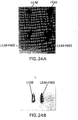
- Fishing applications include, for example, jigheads, worm weights, crankbait weights, split shot, weighted hooks, jigging spoons, bait walkers and bottom bouncers. The present inventors have constructed jigheads and worm weights utilizing a tungsten powder/Nylon 12® composite. These weights, which have a density of about 1 1.0g/cc, are shown in FIG. 24.
- model trains engines depend on having the maximum possible engine weight to prevent wheel slippage. These engines are manufactured to scale and space inside these small models is limited, so that high density is important in obtaining the desired overall weight in scale with the model proportions. Engine frames molded from this material are one application. Also, "add-on" weights made of the present material would be utilized not only in model train engines, but in train cars as well.
- FIG. 25 shows a commercially available lead model train add-on weight with a lead-free weight that is made of tungsten powder/nylon and has a density of about 11.0g/cc.
- Tungsten is an excellent radiation shield material, but is difficult to work with in solid form.
- the injection moldable lead replacement according to the present invention solves this problem, since the material may be used to form radiation shield parts for all members of the medical x-ray and gamma ray equipment industry. This high density material has the advantage of superior structural strength when compared to lead. Also, the material may be used to manufacture clothing used by radiation industry workers for protection against the effects of ionizing radiation.
- Sheet material of tungsten composite materials were placed on a piece of x-ray film with 6 pieces of lead of varying thickness' up to 6.35 mm (0.25 inches).
- the samples of the present invention were compared to lead of 3.175 mm (0.125 inches) thick.
- the samples were irradiated, and the film was developed and assessed for the ability of the samples to prevent film fogging.
- material 6.35 mm (0.250 inches) thick and comprising the Nylon 12®/polymer mix as set forth above had a shielding equivalency of approximately that of 3.81 mm (0.150 inches) of sheet lead.
- material 12.7 mm (0.50 inches) thick, and comprising the Nylon 12® sample with stainless steel fibers as set forth above yielded an approximate shielding equivalency of 4.75 mm (0.187 inches) of sheet lead.
- a third example was 9.53 mm (0.375 inches) thick and flexible in form, had a shielding equivalency of between about 23.9 and 3.175 mm(0.94 and 0.125 inches) of lead.
- samples of the composites of the present invention were tested for their mechanical properties as radiation shield components.
- Sample A1 was a tungsten/Nylon 12® non irradiated composite
- sample A2 was a tungsten/Nylon 12® composite irradiated with 38400 Roentgens
- sample B1 was a tungsten/Nylon 12®/stainless steel fiber, non-irradiated composite
- sample B2 was a tungsten/Nylon 12®/stainless steel fiber composite irradiated with 38400 Roentgens.
- Samples A1, B1, A2 and B2 were conditioned at 25°C and 50% RH for a period of 48 hours in an environmental chamber prior to testing. The samples were then tested in a universal testing machine using a crosshead control method. The results are presented in Table 33.
- a polyurethane resin putty and tungsten powder are mixed with an activator, which cures to form a flexible material.
- 100 grams of putty is mixed with 10 grams of ETHACURE 300 curative and allowed to cure at room temperature.
- thermosetting materials include those listed in Table 34 and Table 35 below.
- Table 34 lists possible thermoplastic materials that can be filled with the tungsten powder compositions of the present invention.
- Table 35 shows examples of thermoset materials for use in the present invention.
- Table 34 Thermoplastic Materials that can be used in the composites of the present invention Acrylics Polymethyl Methacrylate Homopolymer and Coppolymer Acetals Polyoxymethylenes Acrylonitrile-Butadiene-Styrene Monsanto, Dow Chemical, Borg Warnar Chemicals Cycolac tradename Major Supplier Thermoplastic Fluoropolymers Coflon (polyvinylidene fluoride) Ionomers Surlyn tradename for DuPont Product Polyamides Nylons Polyamide-imides Condensation product of aromatic diamines and trimellitic anhydride Polyacrylates Polyhydroxyethylmethacrylate Polyetherketones Amoco Performance Products Polyaryl Sulfones Amoco Performance Products Polybenzimidazoles
- Tungsten powder with a thermosetting Epoxy is as follows. 27.7 grams of Tungsten powder was weighed in a beaker and set aside. Subsequently 5.0 grams of Epon 8111 of an acrylate modified epoxy was weighed into another container to which was immediately added 0.5 grams of Shell Epi-Cure 3271. Then 3.6 grams of the mixed epoxy and curing agent was added to the 27.7 grams of Teledyne C-8 Tungsten powder. The powder and the epoxy were hand mixed, placed between two Teflon sheets and allowed to cure overnight. A flexible sample of Tungsten powder epoxy was produced.
- a polyurethane rigid foam can also be produced using the compositions of the present invention.
- the foam was produced by adding 238 grams of Teledyne C8 Tungsten powder to 109.9 grams of Premium Polymer 475-20 B component and the mixture was stirred. Next 120 grams of Premium Polymer 475-20 A component was added and the slurry stirred for approximately twenty seconds. The slurry was placed in a container. It quickly rose and was tack free within two minutes. The tungsten powder was uniformly distributed throughout the foam. It is envisioned that the foam material may be employed in a binder capacity as defined elsewhere herein. The high density foam will find utility in noise and vibration damping, in radiation shielding and the like.
- compositions of the present invention may be employed to produce a high density, low viscosity slurry.
- a slurry may be employed in list systems of deep submerge rescue vessels or remote operated vehicles, in a manner similar to the current uses of mercury therein.
- mercury is transferred between spherical chambers to cause list to port or starboard or to change the distance between the center of buoyancy and the center of gravity.
- the list system of such vessels involves the transfer of approximately 1270 kg (2800-pounds) of mercury between a reservoir which is low and centered athwart ships and the port and starboard wing tanks which are located 45° above the horizontal and as far outboard as possible. All the tanks are spherical and equipped with a diaphragm, which is actuated by hydraulic fluid to displace the mercury.
- the spherical tanks are located between and in close proximity to the center and aft personnel spheres, the skin and the structural rings that serve as the aft support for the personnel pressure capsule.
- the tanks are connected by 3.175 cm (1.25 inch) outside diameter stainless steel tubing and the mercury can be transferred between the reservoir and a wing tank in 45 seconds representing a flow of about 25gpm.
- compositions of the present invention provide a high density composite material that may be used as a weight medium for trim and list systems. Such compositions may be configured into a high density slurry comprising solvents, suspension agents, surfactants and lubricants.
- the high density material of the present invention may be in the form of high density balls or in the form of a powder mixture in the slurry.
- the solvent of choice may be a perfluorpolyether
- other examples include castor oils, tricresyl phosphate, polyoxypropylene ether glycols, polymethylphenyl siloxane, fluorosilicone, paratherm NF, therminol, dynalene, tribolube F-219, perfluorinated hydrocarbons, fomalin 1818 perfluorpolyether, Voranol 5070 perfluorpolyether, Voranol perfluorpolyether 5004, and Voranol perfluorpolyether 2004. These fluids exhibit good viscosity, compatibility, and volatility and are compatible with stainless steel, tungsten, Teflon, synthetic rubber and Viton.
- the surfactant of choice may be anionic, cationic or nonanionic in nature. Silicon and fluorosilicone surfactants may also be employed.
- the tungsten composites of the present invention may be in powder form or in the form a balls. Polymeric encapsulation may be employed with the tungsten powder or balls to reduce friction in the slurry. Urea-formaldehyde emulsions, glyco diols and melamine formaldehyde compositions are good candidates as encapsulations materials.
- 700g tungsten powder (2-4 micron) are mixed with 100g 60wt. motor oil (specific gravity 1.1) and 800g ballast material 1 (specific gravity 6.3).
- 350g tungsten powder (8-10 microns) are blend with 50g 80-140wt. gear case oil (specific gravity 1.1), and 400g of ballast material 2 (specific gravity 6.3).
Landscapes
- Chemical & Material Sciences (AREA)
- Engineering & Computer Science (AREA)
- Organic Chemistry (AREA)
- Materials Engineering (AREA)
- Mechanical Engineering (AREA)
- Metallurgy (AREA)
- Polymers & Plastics (AREA)
- Medicinal Chemistry (AREA)
- Chemical Kinetics & Catalysis (AREA)
- Health & Medical Sciences (AREA)
- General Engineering & Computer Science (AREA)
- Life Sciences & Earth Sciences (AREA)
- Dispersion Chemistry (AREA)
- Physics & Mathematics (AREA)
- Environmental Sciences (AREA)
- Biodiversity & Conservation Biology (AREA)
- Animal Husbandry (AREA)
- High Energy & Nuclear Physics (AREA)
- Thermal Sciences (AREA)
- Combustion & Propulsion (AREA)
- Compositions Of Macromolecular Compounds (AREA)
- Reinforced Plastic Materials (AREA)
- Inorganic Compounds Of Heavy Metals (AREA)
- Inorganic Insulating Materials (AREA)
Abstract
Description
- The present invention relates generally to the fields of polymers and high density compositions. More particularly, it concerns materials that may act as a replacement for lead in applications requiring lead's high density, but where the toxic effects of lead are undesirable. Further, the high density composites of the present invention may be employed in any application where a high density material is required.
- Each year, approximately 689 million rounds of small arms ammunition (.22 caliber through .50 caliber) are fired during training by the Army, Navy, Air Force, Marine Corps, National Guard, and Reserves in the United States. An additional 10 million rounds are fired annually by the Department of Energy. The ammunition projectiles used for this training consist of lead antimony cores, or cores, encased in a copper alloy jacket. Use of these projectiles results in approximately 2,000 tons of lead per year being introduced into the environment. Lead contamination of soil, sediments, surface and groundwater have been confirmed through investigations conducted at Army, Navy, Air Force, Marine Corps, Coast Guard and private small arms ranges throughout the United States and Europe. Lead uptake in vegetation at a Marine Corps small arms range in Quantico, Virginia showed lead levels as high as 23,200 parts per million. Remediation of contaminated ranges has proven to be extremely expensive and provides only a temporary solution. The Navy reports hazardous waste removal from one small arms firing berm cost $2.5 million with an additional $100, 000 per year required for lead contamination monitoring. Sixteen Navy small arms firing ranges are now required to improve hazardous waste maintenance at a predicted cost of $37.2 million. In addition, the September 1995 "Cost Analysis for Munitions Rule" prepared by the U.S. Army Concepts Analysis Agency indicate the cost to remediate an outdoor small arms range is approximately $150, 000 per acre. Currently there are 120 ranges closing or scheduled to be closed as a result of Base Realignment and Closure recommendations which account for an estimated 4,185 acres or a total of $627 million.
- In order for firing ranges to remain open, expensive cleanup procedures must be employed that provide only a temporary solution to the problem. A non-toxic, lead-free, environmentally safe, cost effective replacement projectile core material is required to enable firing ranges to remain open and to eliminate costly cleanup procedures. The density of the projectile should be close to that of a lead projectile for realistic performance simulation. Materials of a lower density decrease projectile range and penetration.
- In addition, there is mounting concern over the use of lead shot for bird hunting, due to ingestion of the shot by birds and other animals as well as contamination of wetland areas. Indeed there has been legislation in the United States and other countries which bans the use of lead shots in waterfowl shots. Moreover, such a lead substitute or high density material will find many other applications, such as for weights, acoustic dampening or vibration dampening, and in radiation shielding applications, including protective clothing, medical clothing and clothing for use in nuclear reactors.
- The present invention, in a general and overall sense, concerns a family of materials that may act as a replacement for lead in applications where the high density of lead is important, but where the toxicity of lead is undesirable. Thus there is presented in a particular aspect a high density composite for use in applications in which lead or any other high density material may be required.
- According to the present invention, there is provided a high density composition of matter comprising a metal powder and a binder, wherein the method powder particle size is between 2 and 40 microns in diameter, wherein the metal powder is a blend with a distributor of different particle sizes, and wherein said metal is tungsten.
- In a particular embodiment, there is provided a high density composition of matter, comprising tungsten powder, a fiber and a binder material. In particular embodiments, the tungsten comprises between about 5% and about 95% of the composite. In other embodiments, the tungsten comprises between about 10% and about 80% of the composite. In other embodiments, the tungsten comprises between about 15% and about 70% of the composite. In alternate embodiments, the tungsten comprises between about 25% and about 50% of the composite. In other embodiments, the tungsten comprises between about 35% and about 40% of the composite. Of course these are exemplary percentages and the tungsten may comprise any percentage between these figures, for example, about 5%, 6%, 7%, 8%, 9%, 12%, 14%, 16%, 20%, 21%, 22%, 23%, 24%, 26%, 28%, 30%, 32%, 34%, 36%, 38%, 42%, 44%, 46%, 48%, 52%, 54%, 56%, 58%, 60%, 62%, 64%, 66%, 68%, 72%, 74%, 76%, 78%, 82%, 84%, 86%, or 88% of the composite weight.
- The tungsten powder particle size is between about 2 and about 40 microns in diameter. In one embodiment the tungsten powder particle size is between about 4 and about 8 microns in diameter. In yet another embodiment, the tungsten powder particle size is between about 20 and about 40 microns diameter. Of course these are exemplary measurements and the powder may comprise a particle size of about 4, 5, 6, 7, 9, 10, 11, 12, 14, 16, 18, 21, 22, 23, 24, 25, 28, 30, 31, 32, 33, 34, 35, 36, 37, 38 or 39 microns in diameter. It is desirable to have tungsten powder comprised of particles having varying sizes of diameter.
- In a particular embodiment of the present invention, the fiber may comprise stainless steel, copper, aluminum, nylon, Kevlar®, Spectra®, nickel, glass or carbon. In more particular aspects, the fiber is stainless steel fiber. In preferred embodiments, the fiber comprises between about 3% and about 30% of the composite weight. In other aspects the fiber comprises between about 10% and about 20% of the composite weight. In alternate embodiments, the fiber comprises between about 15% and about 18% of the composite weight. Of course these are exemplary percentages and the fiber may comprise any percentage between these figures, for example, about 4%, 5%, 6%, 7%, 8%, 9%, 10%, 12%, 14%, 16%, 19%, 21%, 22%, 23%, 24%, 25%, 26%, 27%, 28% or 29% of the composite weight.
- In yet another aspect of the present invention the binder is a polymeric binder. In particular aspects the polymeric binder may be selected from the group consisting of cellulose, fluoro-polymer, ethylene inter-polymer alloy elastomer, ethylene vinyl acetate, ionomer, nylon, polythermide, polyester elastomer, polyester sulfone, polyphenyl amide, polypropylene, polyvinylidene fluoride or thermoset polyurea elastomer.
- In more particular embodiments, the polymeric binder is Nylon 12® and polyester elastomer. In more specific embodiments the polymeric binder comprises between about 1% to about 30% weight ratio of the composite. In other embodiments, the polymeric binder is at a concentration of about 2% to about 20% weight ratio. In still further embodiments, the polymeric binder comprises between about 5% to about 15% weight ratio of the composite. In other embodiments, the polymeric binder comprises between about 8% to about 12% weight ratio of the composite.
- In particular embodiments the high density composition may be utilized as a radiation shielding material. In other embodiments, the radiation shielding material is a flexible shielding material. In further embodiments, the composition may be utilized as modeling weights, fishing weights, flywheels, or projectiles.
- Other objects, features and advantages of the present invention will become apparent from the following detailed description. It should be understood, however, that the detailed description and the specific examples, while indicating preferred embodiments of the invention, are given by way of illustration only.
- The following drawings form part of the present specification and are included to further demonstrate certain aspects of the present invention. The invention may be better understood by reference to one or more of these drawings in combination with the detailed description of specific embodiments presented herein.
- FIG. 1 shows a picture of compression molded tungsten powder/polymeric binder flexural test bars.
- FIG. 2 shows a picture of the three point bend flexural test fixture and a flexural test bar installed in an Instron testing machine. A- support pins; B- center pin with cylindrical tap; C- flexural test bar; D- support base.
- FIG. 3 shows the maximum flexural load (1b) for various polymeric binders.
- FIG. 4 shows the flexural strength (psi) for various polymeric binders.
- FIG. 5 shows the maximum flexural displacement (in.) for various polymeric binders.
- FIG. 6 shows the flexural modulus (psi) for various polymeric binders.
- FIG. 7 shows a fractured tensile test bar after being pulled in the Instron tensile testing machine.
- FIG. 8 compares the tensile strengths of
Nylon 12®/Stainless Steel fiber composite,Nylon 12® composite, polyester elastomer composite and lead. - FIG. 9 shows the elongation at break of
Nylon 12®/Stainless Steel fiber composite,Nylon 12® composite , polyester elastomer composite and lead. - FIG. 10 shows the tensile modulus (ksi) of
Nylon 12®/Stainless Steel fiber composite,Nylon 12® composite, polyester elastomer composite and lead. - FIG. 11 shows a test specimen four cavity model injection mold. A-
ASTM D638 Type 1 tensile bar; B- impact disc; C- impact bar; D- ASTM D638 Type V tensile bar. - FIG. 12 shows a picture of the injection molded composite material tensile test bars. A- broken tensile test bar after tensile test;
- FIG. 13 shows a picture of a tungsten powder polymer binder injection molded projectile core (C), a lead projectile core (B), and a copper jacketed lead projectile core (A).
- FIG. 14 shows a vertical drop compressive impact test that provides a qualitative assessment of the impact performance of the TPP composite material projectile cores and lead projectile cores.
- FIG. 15 shows vertical drop (15.24 cm (6 inch) drop height) impact test results for
Nylon 12® tungsten powder composite projectile core and lead for comparison. - FIG. 16 shows vertical drop (30.48cm (12 inch) drop height) impact test results for
Nylon 12® tungsten powder composite projectile core and lead for comparison. - FIG. 17 shows vertical drop (45.72cm (18 inch) drop height) impact test results for
Nylon 12® tungsten powder composite projectile core and lead for comparison. - FIG. 18 shows vertical drop (15.24 cm (6 inch) drop height) impact test results for
Nylon 12® tungsten powder with stainless steel fiber composite projectile core. - FIG. 19 shows vertical drop (30.48cm (12 inch) drop height) impact test results for
Nylon 12® tungsten powder with stainless steel fiber composite projectile core. - FIG. 20 shows vertical drop (45.72cm (18 inch) drop height) impact test results for
Nylon 12® tungsten powder with stainless steel fiber composite projectile core. - FIG. 21 shows vertical drop (15.24 cm (6 inch) drop height) impact test results for polyester elastomer (
TEXIN 480A) tungsten powder with stainless steel fiber composite projectile core. - FIG. 22 shows vertical drop (30.48cm (12 inch) drop height) impact test results for polyester elastomer (
TEXIN 480A) tungsten powder with stainless steel fiber composite projectile core. - FIG. 23 shows vertical drop (45.72cm (18 inch) drop height) impact test results for polyester elastomer (
TEXIN 480A) tungsten powder with stainless steel fiber composite projectile core. - FIG. 24 shows non-toxic lead-free fishing weight prototypes and their lead counterparts.
- FIG. 25 shows model train weights. A commercially available lead model train add-on weight is shown on the left and a lead-free prototype compression molded by of the present invention is shown in the center. Lead-free bar-stock is shown on the right. The lead-free train weights are made of tungsten powder and have a density of 11.0g/cc.
- FIG. 26 shows a design drawing of a 7.62 mm projectile core (slug).
- FIG. 27 shows a design drawing of a 7.62 mm bullet.
- FIG. 28 shows a design drawing of a 7.62 mm M80 Nato Ball Cartridge.
- FIG. 29 shows a design drawing of prototype 7.62 mm projectile core single cavity injection mold.
- FIG. 30A, FIG. 30B and FIG. 30C show inspection results depicting slug weight (FIG. 30A), slug length (FIG. 30B) and slug diameter (FIG. 30C) for tungsten/
Nylon 12® and tungsten/Nylon 12®/stainless steel composites. - FIG. 31 shows an illustration of penetration depth, length and height of the temporary cavity made by firing of projectiles of the present invention into ballistic gelatin.
- FIG. 32 Set up for toxic fume test (top view).
- Lead from spent lead bullets represents a major source of environmental pollution as well as posing a potential health risk to both shooters and range personnel alike. Lead bullet residue left in the earthen berms of outdoor ranges can leach into the soil and contaminate water tables. Indoor ranges require extensive and expensive air filtration systems to operate safely as lead is introduced into the atmosphere as the projectile exits the barrel. Improved bullet traps are also required to permit lead collection and recycling. Outdoor ranges require constant soil remediation.
- The present invention provides compositions that may be used as lead substitutes, having a density similar to or greater than lead and being substantially less toxic to the user. The compositions of the present invention thus provide a new, relatively non-toxic, high performance replacement for metallic lead that can play a part in the ongoing transition from environmentally hazardous materials to ecologically acceptable ones. The compositions of the present will be useful not only in the manufacture of ammunitions but also in any applications requiring the use of a high density material. For example, the materials are useful as weights, such as counterweights, fishing weights, wheel weights, flywheels or for use in model applications, such as in model railroading. Other similar applications include use as an acoustic dampening or vibration dampening material. Also, the high density material will find use in radiation shielding applications, for example, in radiotherapy and routine X-ray examinations and those applications requiring a radiation shielding compound that may be placed in small spaces, such as cracks. As defined herein "high density" refers to a density that is near to or higher than the density of lead.
- As stated earlier, the compositions of the present invention may be used in the manufacture of practice ammunition for all types of rifles and pistols. If the lead-free projectiles are also frangible, they have applications when ricochet poses a danger to innocent parties. Applications for frangible non-toxic projectiles includes indoor/outdoor firing ranges; police and military training and qualification; commercial institutions; industrial installations; banks; prisons/jails; nuclear power plants; chemical processing plants; hospitals; and universities.
- The non-toxic projectile core technology of the present invention may be used to replace lead shotgun pellets, now prohibited for use in waterfowl hunting. The tungsten-based pellets will have similar performance to lead shot, unlike steel shot that is currently being used as a replacement for lead shot. Bismuth is also used, but this material is not as dense as lead, making it an undesirable material in lead shot replacement. Rifled slugs for shotguns and air rifle pellets may also be manufactured utilizing the non-toxic tungsten formulations according to the present invention.
- Further, the compounds may be formed into sheets or blocks useful in radiation shielding applications. Also it is contemplated that the high density materials of the present invention can be machined to form complex shields, housings or assemblies. Other radiation shielding applications include use in clothing worn by personnel exposed to radiation sources. Such dense, and non-toxic materials may further be formulated to be flexible and will find applications in protective clothing and other protective gear for medical and dental personnel, persons involved in the nuclear power or defense industries, and any other application where such clothing or apparel is worn. Lead is a soft, toxic and structurally weak metal and is therefore unsuitable for certain such applications.
- The material may be injection or compression molded into a variety of shapes. Injection molding fabrication using the material allows for high volume, low cost fabrication. Products utilizing the high density materials of the present invention may also be fabricated using thermoset and thermoplastic extrusion, thermoset and thermoplastic pultrusion, compression, centrifugal molding, rotational molding, blow molding, casting, calendering, liquid fill thermoset molding or filament winding to form a variety of shapes.
- The material of the present formulations comprises a tungsten powder as a high density component. Tungsten powder is relatively non-toxic and is suitable for commercial applications. Because solid metallic tungsten is a very hard material and melts at an extremely high temperature (approx. 3410°C, the highest melting point of all metals), the present formulations allows injection and compression molding and other previously mentioned methods, thus avoiding difficulties that may be encountered with working with pure tungsten.
- A novel aspect of the present formulations is the use of fibers to form a composite material comprising tungsten powder, polymeric binders, and fibers. The fibers may be stainless steel, or other metallic fibers such as copper, nickel, niobium, or titanium. Alternatively, non-metallic fibers, such as glass fibers, Kevlar®, Spectra®, graphite, carbon, or boron, may be used to increase the tensile strength of the composition. It is possible to enhance the physical properties of the composition by adding various fibers, either singly or in combination with each other. For example, use of fibers softer than steel, such as glass, cellulose, cotton, nickel or copper fibers, may result in reduction of barrel wear in projectile applications.
- Another aspect of the invention is the use of thermoplastic and thermoset materials as a polymeric binder. Each type of binder may be used to vary the physical properties of the composite, for example from very hard to soft and flexible. As used herein, "TPP" means tungsten powder/polymeric binder composite materials. In certain embodiments, the binder may be a hot melt or thermosetting type of glue. In particular embodiments, the thermoset may comprise a single component whereas in other embodiments, the thermosets comprise a plurality of components.
- The properties of the composition may be varied as well by the use of tungsten powders of different particle sizes. The composition comprises a tungsten powder blend with a distribution of different particle sizes.
- In certain aspects, equal portions of a tungsten powder with size distributions of about 2-4 microns, about 4-8 microns, and about 20-40 microns which are mixed with fibers and polymeric binder. Stainless steel fibers are added, for example, at about 5% by volume with the composition to improve tensile strength.
- As previously mentioned, the compositions of the present invention may be used as ionizing radiation shielding that is relatively non-toxic and easy to apply. In this aspect, tungsten powder is mixed with the bulk component of a two-part curing resin system, such as an epoxy resin. The resultant mixture, having the viscosity of a caulking compound, is easily stored until ready for use. Prior to application, a catalyst is added and the mixture is thoroughly stirred. The material may then be applied to any surface, for example into cracks, and allowed to cure. The resulting cured material could, for example, then serve as a patch for radiation leaks in a radiation shielding system. In other applications, the composition may be used as radiation shielding in clinical applications, for example to form shields for use in radiation therapy procedures. Alternatively it will be possible to employ the compositions of the present invention in making aprons, gloves or other apparel and shields for use in applications such as, for example, X-ray examinations.
- In other aspects, the formulations of the present invention are useful in making a lead-free projectile, which comprises, for example, a powder material that may be tungsten, tungsten carbide, ferrotungsten, and the like. The formulation also comprises a fiber material that may be, for example, stainless steel, copper, glass, zinc, and the like. Additionally, the formulation comprises a binder material that may be a two-part curing resin, such as epoxy resin, polyurethane or polyester resin, or other polymer material. One-component thermosets are often cure initiated by air or moisture.
- In certain other aspects of the invention, methods are provided for molding articles of the present invention into a variety of shapes, including projectiles, shot, radiation shielding blocks, custom radiation shields with complex geometry, and the like. Also provided are methods of preparing the formulations into a putty-like consistency that may be applied into cracks or holes to block radiation passage. The compositions of the present invention and methods for making and using such compositions are described in further detail herein below.
- Table 1 presents a list of elemental metals that were considered as potential candidates for use as lead substitutes in high density compositions . From the list of metals with a specific gravity greater than lead, it is evident that tungsten meets the physical requirements of high density. Furthermore, tungsten has a low toxicity, making it an excellent metal of choice in lead substitutes and other high density materials.
Table 1 Potential Candidate Base Metals and Alloying Metals Elemental Metal Specific Gravity Potential Base Metals Osmium 22.48 Iridium 22.42 Platinum 21.45 Rhenium 20.53 Tungsten 19.35 Gold 18.88 Tantalum 16.60 Hafnium 13.31 Rhodium 12.40 Ruthenium 12.30 Palladium 12.02 Thallium 11.85 Lead 11.43 Potential Alloying Metals Silver 10.50 Molybdenum 10.20 Bismuth 9.80 Copper 8.92 Cobalt 8.90 Nickel 8.90 Cadmium 8.64 Niobium 8.57 Iron 7.86 - The great advantage of tungsten as a lead substitute material is that, in addition to being comparatively non-toxic, it has a very high density (19.25 g/cc). Commercially available tungsten powders can therefore be mixed and pressed with softer and lighter non-toxic metals, such as tin or zinc, to generate lead substitute materials with a range of densities as high as, or even higher than, that of lead.
- In certain instances, copper was found to have a number of advantages as a useful material. It is relatively non-toxic and is widely accepted by the shooting community through its extensive use as a jacketing metal for lead projectiles. Solid copper has a reasonably high density of 8.96 g/cc, which is about 80% of that of lead.
- A survey of the periodic table of elements shows that metals with densities higher than copper (such as silver, gold, tungsten, bismuth) are considerably more expensive than copper and have previously been rejected as possible replacements for lead on grounds of affordability, however the methods and compositions of the present invention make these materials a useful and affordable alternative to lead and copper in some applications. Finally, the high melting and boiling points of copper ensure that very little of the copper metal will vaporize into an easily breathable form (so called copper fume) either at the firing point or on bullet impact with indoor range steel baffling on bullet traps.
- Copper in the metallic and powder form is not a severe pollutant. It is widely used in military stores. Nearly all small arms cartridge cases are made from brass (an alloy of copper and zinc). Its excellent lubricating and flow characteristics also make it the metal of choice for jacketing lead cores in small arms bullets. The price of copper is also sufficiently high to ensure that brass cartridge cases are always either reused or recovered for scrap. Expended copper bullet jackets also have value and can be recovered and recycled as scrap copper, further assisting reclamation of waste materials and protection of the environment. Copper alloys such as brass and bronze can also be used to make bullets. These alloys are harder than copper and need to be pressed at higher pressures and sintered at lower temperatures.
- Non-toxic metals such as zinc and tin are also potential candidates to replace lead but, being less dense than copper and tungsten, may suffer from problems arising from lower projectile mass such as compatibility with commercially available propellants, reliable cycling and feeding of weapons, realistic recoil energies and matching the trajectory of lead projectiles. However, the present invention circumvents this problem by providing methods of making composite materials that make the material more dense. More volatile metals than copper, such as tin and zinc, are also prone to forming ingestible vapors at the high temperatures generated during bullet impact on steel plates.
- Metals such as gold, silver, platinum and palladium also have densities that are close to or greater than the density of lead and would therefore, be suitable as materials for the composites of the present invention. The drawback with these metals is that they are expensive; however, the present invention combines metals of a high density with, for example,
Nylon 11® orNylon 12® in order to make such composites more cost effective. Further other non-metallic components may be used in combination with the disclosed compositions to form a material of the requisite density in a relatively cost effective manner. Such non-metallic components may include mineral ores for example, hematite. - In certain applications where projectiles are made, employing tungsten as a component, it is possible to demonstrate a uniform blending of the metal powders, essential to ensure consistent projectiles and other articles described in the present invention. Furthermore, the composite projectiles match standard ball ammunition, both in weight and trajectory, over realistic training distances. Lead substitutes using tungsten powder as a component are frangible but they tend to be much more penetrating against metal plates than other metal loaded polymer projectiles.
- In order to reduce the cost and add strength to a tungsten powder/polymeric binder composite material, the present inventors have added metal fibers at a low volume fraction. The inventors performed a survey to identify suitable metal fibers for use in a projectile core application. The metal fibers need to possess high strength, high specific gravity and have a low cost. The survey revealed that the most cost effective metal fibers with high strength and specific gravity are chopped stainless steel fibers. Stainless steel fibers are readily available and are currently being added to injection moldable polymer resins at up to a 30% volume ratio for electromagnetic shielding applications. Fiber made from 316 stainless steel with a length of 0.125 inches, a thickness of 75 microns, a specific gravity of 8.0 was selected as a representative tungsten powder/polymeric binder material additive. In other embodiments, any of the metals listed in Table 1, may further be formulated into fibers for use in the present invention.
- Once tungsten was selected as the candidate metal powder, a survey was performed to identify potential polymeric binders for the tungsten powder. As used herein a "binder" is a material that is used to provide cohesion between the high density metal powder and the fibers such that the integrity of the metal and the fiber is maintained.
- Table 2 presents a summary of selected properties for polymeric binders considered for mixing with tungsten powder. The selection criteria used to form this list of potential polymeric binder materials included good ductility (high elongation values), high strength, high modulus, high melting temperatures, high impact strength, low water absorption and low cost. The
Nylon 6® andNylon Polamine 1000 formulation. ThePolamine 1000 polyurea elastomer formulation is prepared by mixing 38.02g Dow 2.143L (a modified diphenylmethane diisocyanate) and 150g Polamine 1000 (an amine terminated polytetramethylene ether made by Air Products) with Teledyne C-8 tungsten powder for a final product density of 10.33g/cc. This material is referred to hereinafter as "TRI/Austin MDI/Polamine 1000 formulation".Table 2. Selected Properties of Candidate Binders Polymeric binder Manufacturer (Grade) Spec. Grav. Melting Point [°C(F)] Heat Deflection Temp.at 1813 Kpa (263 psi) [°C(F)] Tensile Strength [kPa (psi)] Elongation At Yield (%) Elongation At Break (%) Tensil Modulus [MPa (ksi)] Flexural Modulus [Mpa (ksi)] Notched Izod Impact Strength [J/m (ft-lb/in)] Water Absorption at 24 hr. Immersion (%) Cellulose Based Planet Polymers (PT-C300ZT) 1.29 182(360) 52 (125) 426 23 (6,182) --- 11 2330 (338) 2848(413) 69.4(1.3) --- ECTFE Fluoro-polymer Ausimont (Halar 5001LC) 1.68 238(460) 67(153) 45505(6,600) --- 260 --- 1669(242) N.B. 0.10 Ethylene Inter-polymer Alloy Elasto-mer DuPont (ALCRYN 2070NC) 1.20 185(365) --- 8274(1,200) 9 375 --- --- --- --- Ethylene - Vinyl Acetate Polymer DuPont (ELVAX 360) 0.95 213(415) --- 17926(2,600) --- 800 --- 25.5(3.7) --- Ionomer DuPont (Surlyn 8220) 0.95 241(480) --- 38611(5,600) --- 305 --- 545(79) N.B. --- Nylon 6® Hoechst Celenase (2800) 1.13 215(419) 64(147) 78600(11,400) --- 80 2999(435) 2723(395) 58.7(1.1) 1.70 Nylon6,6® Hoechst Celanese (1000) 1.14 257(495) 88(190) 75842 (11,000) --- 300 --- 2896(420) 112(2.1) 1.50 Nylon 11® Atochem (BMFO) 1.04 186 (367) 46 (115) 68948 (10,000) --- 390 --- 1172 (170) --- 0.30 Nylon 12® EMS-American (Grilamide L20GHS) 1.01 178 (352) 55(131) 51711 (7,500) 20 320 --- 869 (126) 68.4 (1.3) 0.23 Polythermide (PEI) GE (Ultem 1000) 1.27 357(675) 200(392) 104800(15,200) 7 60 --- 3309(480) 53.4(1.0) 0.25 Polyester Elastomer Bayer (Texin 480-A) 1.20 196(385) --- 41369(6,000) --- 500 11.7(1.7) 31.0(4.5) --- --- Polyester-sulfone (PES) BASF (Ultrason E1010) 1.37 360(680) --- 89632(13,000) --- 6.7 2620(380) --- 694(13.0) 0.30 Polyphtalamide (PPA) AMOCO (Amodel ET-1001) 1.15 310(590) 120(248) 75842 (11,000) 6 30 2413(350) 2620 (380) 961(18.0) 0.68 Polypropylene AMOCO (ACCTUF 3434) 0.91 232(450) --- 27579(4,000) 9 500 --- 1379(200) 181(3.4) 0.03 Polyvinylidene Flouride (PVDF) Ausimont (Hylar 461) 1.77 157(315) 85(185) 51711(7,500) --- 250 1379(200) 1793(260) 160(3.0) 0.04 Thermoset Polyurea Elastomer TRIAustin (MDI/Polamine 1000) --- --- 55158(8,000) --- 460 14.5(2.1) --- --- --- - Methods of making projectiles, shielding devices and other applications described herein are well known to those of skill in the art. The skilled artisan is referred to US Patent Nos 5,264,022; 5,399,187; 5,189,252; 4,949,645, and WO 9316349 for details on the use of alloys in the preparation of projectiles. US Patent No. 5,081,786 and WO publication No. 9208346 describe methods of constructing fishing lures from metal alloys, such methods may be employed in combination with the compositions of the present invention. Methods of making radiological shielding devices and clothing or other apparel are well known to those of skill in the art.
- The following examples are included to demonstrate preferred embodiments of the invention. It should be appreciated by those of skill in the art that the techniques disclosed in the examples which follow represent techniques discovered by the inventor to function well in the practice of the invention, and thus can be considered to constitute preferred modes for its practice.
- The material testing consisted of performing flexural three point bend tests on compression molded tungsten powder/polymeric binder flexural test bars and performing tensile tests on injection molded tungsten powder (and stainless steel fiber) polymeric binder tensile test bars. The flexural testing was used to screen the large number of candidate polymer mixtures and to select several optimal materials for injection molding. The tensile testing was performed to compare the material properties of each candidate injection molded composite mixture and lead.
- Eleven candidate thermoplastic polymeric binders were successfully mixed with tungsten powder in a Brabender mixer. Each polymeric binder was mixed with the tungsten powder in a 50% volume ratio (25cc of tungsten powder and 25cc of polymeric binder). The tungsten powder had an equal distribution of particle sizes ranging from about 2 to about 20 microns. Each of the tungsten powder/polymeric binder mixtures was removed from the Brabender mixer and ground into particles using a laboratory grinder. Each mixture was then compression molded into flexural test bars using a hydraulic compression molding machine. Figure 1 shows a picture of compression molded tungsten powder/polymeric binder flexural test bars. One thermoset polymeric binder (TRI/Austin MDI/
Polamine 1000 formulation) was mixed with tungsten powder in a standard rotary mixer using a 50% volume ratio. The tungsten powder thermoset polymeric binder mixture was placed into a flat plate compression mold. The mold was put into a hydraulic compression molding machine and was allowed to cure overnight at room temperature under clamping pressure. Flexural test bars were punched from the flat plate using a flexural test bar stamping die. All of the flexural test bars had the following dimensions; 6.35 cm (2.5 inch) length by 1.27 cm (0.5 inch) width by 0.3175 cm (0.125 inch) thickness. Table 3 provides the average measured specific gravity for each of the polymeric binders used. The flexural test bars had a specific gravity ranging from 10.00 to 10.63.Table 3 Specific Gravity of Compression Molded Tungsten powder/polymeric binder Flexural Test Bars Polymeric binder Specific Gravity Biodegradable Cellulose (Planet Polymers PT-C300ZT) 10.02 ECTFE Flouropolymer (Ausimont Halar 5001LC) 10.63 Ethylene Interpolymer Alloy Elastomer (DuPont Alcryn 2070NC) 10.15 Ethylene - Vinyl Acetate Elastomer (DuPont Elvax 360) 10.48 Ionomer (DuPont Surlyn 8220) 10.00 Nylon 11® (Atochem BMFO)10.10 Nylon 12® (EMS Grilamide L20GHS)10.08 Polytherimide (G.E. Ultem 1000) 10.43 Polyester Thermoplastic Elastomer (Bayer Texin 480-A) 10.43 Polypropylene (AMOCO ACCTUF 3434) 10.15 Polyvinylidene Flouride (Ausimont Hylar 461) 10.00 Thermoset Polyurea (TRI/Austin MDI/ Polamine 1000 Formulation)10.33 - Six compression molded flexural test bars of each tungsten powder/polymeric binder mixture from Table 3 were subjected to a three point bend flexural test. Figure 2 shows a picture of the three point bend flexural test fixture and a flexural test bar - installed in an Instron testing machine. Each of the flexural bars was tested to failure using a modified ASTM D790 standard flexural test method. Figures 3 through 6 present the results from the flexural testing. The test results indicate that a wide range in flexural strength, displacement and modulus can be obtained by mixing different polymeric binders with tungsten powder. The elastomeric polymeric binders (ALCRYN 2070NC,
ELVAX 360,TEXIN 480A and the polyurea thermoset) showed the most ductile behavior having the lowest flexural strength and modulus, and the highest flexural displacement. The high melt temperature polyetherimide (ULTEM 1000) mixture had the highest flexural strength and modulus but exhibited a brittle behavior with a low flexural displacement. TheNylon 12® (GRILAMIDE L20GHS) exhibited the second highest flexural strength and the highest flexural displacement excluding the elastomeric polymeric binders, but had a relatively low flexural modulus. Since ductility and strength are of paramount importance in cold forming tungsten powder/polymeric binder projectile cores, theNylon 12® (GRILAMIDE L20GHS) and polyester thermoplastic elastomer (TEXIN 480A) polymeric binders were selected for injection molding into tensile bars and projectile cores. - Tungsten powder/polymeric binder mixtures using the
Nylon 12® (GRILAMMIDE L20GHS) and polyester thermoplastic elastomer (TEXIN 480A) resins were prepared in a Brabender mixer. 700 cc mixtures were prepared for each polymeric binder with a tungsten powder volume ratio of 54%. The tungsten powder had evenly distributed particle sizes ranging from 2 to 20 microns. An additional 700 cc mixture was also prepared for each polymeric binder by adding stainless steel fibers at a 10% volume ratio to theNylon 12® tungsten powder/polymeric binder material. Each mixture was removed from the Brabender mixer and ground into particles using a grinder. Table 4 shows the volume and weight ratios for each mixture. ASTM D638 Type V "dogbone" tensile test bars 6.35 cm (2.5 inch) length by 0.3175 cm (0.125 inch) width by 0.1524 cm (0.06 inch) thickness) were injection molded from each mixture using a Master Precision Mold Test Specimen Four Cavity mold. Figure 12 shows a picture of the injection molded composite material tensile test bars.Table 4 Volume and Weight Ratios for Tensile Bar Composite Materials Mixture Constituent GRILAMIDE L20GHS Nylon 12® TEXIN 480A Polyester Elastomer GRILAMIDE L20GHS Nylon 12® with Stainless Steel FiberVolume Ratio (%) Weight Ratio (%) Volume Ratio (%) Weight Ratio (%) Volume Ratio (%) Weight Ratio (%) Tungsten Powder 54.0 96.0 54.0 95.0 46.0 88.0 Polymeric binder 46.0 4.0 46.0 5.0 44.0 4.0 Stainless Steel Fiber --- --- --- --- 10.0 8.0 - Six tensile bars of each mixture were tested using an Instron tensile testing machine. The tensile tests were performed as per ASTM standard D638 test method. Figure 7 shows a picture of a fractured tensile test bar after being pulled in the Instron tensile testing machine. Figures 8 through 10 show the results from the tensile testing.
- Figure 8 compares the tensile strength of the composite projectile core materials to lead. The
Nylon 12®/tungsten powder/stainless steel fiber composite had the highest tensile strength of the three composite materials. The addition of stainless steel fibers increased the strength of theNylon 12® tungsten powder composite approximately 4.5% from 46670 to 48774 kPa (6,769 to 7,074 psi.) Both of theNylon 12® composite materials had much higher tensile strengths than lead, while the polyester elastomer composite was approximately one third of that of lead. Figure 9 compares the elongation at break values. None of the composite materials showed elongation values as high as the 50% value for tead. The polyester elastomer composite showed the most elongation of the composite showed the most elongation of the composite materials tested with a value of 5.9%. Figure 10 presents the tensile modulus results for the composite materials relative to lead. The addition of stainless steel fiber provided an 8.6% improvement in tensile modulus from 6715 to 7295 MPa (974 to 1,058 ksi) for theNylon 12® composite material. The polyester elastomer had an extremely low modulus of 217 MPa (31.5 ksi) compared to the 16134 MPa (2,340 ksi) modulus of lead. - The tensile test results show that
Nylon 12® composite projectile possess a superior tensile strength and have a reasonably high tensile modulus compared to lead, but are much less ductile than lead. The addition of stainless steel fibers in theNylon 12® composite material substantially increases the tensile strength and modulus with negligible reduction in ductility. The polyester elastomer was the most ductile of the composite materials, but had the lowest tensile strength and modulus. - TPP binder composites with specific gravities in the range of 10 to 11 may be formulated to produce a variation in physical properties, depending on the type of polymeric binder employed. Moreover, the incorporation of fibers, such as stainless steel fibers, into the tungsten powder/polymeric binder composite materials demonstrates an improvement in physical properties of the material.
- Over 150 7.62 mm projectile cores with specific gravities ranging from 10.2 to 11.0 were injection molded using tungsten powder and stainless steel fibers and mixed in a
Nylon 12® and polyester elastomer polymeric binder. - The polymeric binders, such as
Nylon 12®, polyester elastomer, and polyetherimide were compounded with tungsten powder in the ranges of 2 to 4 microns, 4 to 8 microns and 20 to 40 microns, followed by physical evaluation of composite. Larger particle sizes have less total surface area than smaller particle sizes for a given mass of tungsten powder, therefore it is possible to add more of the larger particle size powder with the polymeric binder to produce a more dense TPP composite. In addition, fibers, such as stainless steel fibers, were added to the composite. Fibers may be added in volume ratios such as 10, 20, and 30%. The effect of fiber volume on the physical properties of the TPP composite is evaluated. - Specimens may be injection molded from each of the TPP composite materials compounded as above. Molding of tensile and impact bars may be accomplished using, for example, the Master Precision Mold Test Specimen Four Cavity Model injection mold. See FIG. 11. The mold produces the following test specimens:
- 1. 0.1016 cm (0.04 inch) thick by 6.35 cm (2.5 inch) diameter impact test disc;
- 2. 0.3175 cm (0.125 inch) by 12.7 cm (5.0 inch) impact test bar;
- 3. 0.3175 cm (0.125 inch) by 1.27 cm (0.5 inch) ASTM D638 Type I "dogbone"; and
- 4. 0.1524 cm (0.06 inch) by 0.3175 cm (0.125 inch) ASTM D638 Type V "dogbone"
- FIG. 12 shows an injection molded TPP composite tensile bar. It is contemplated that the methods of the present invention will be utilized to mold ASTM D638 Type I "dogbone" tensile bars for tensile testing and impact test bars will be molded to Izod impact testing.
- Materials properties tests are performed on each selected candidate TPP composite material to evaluate the physical behavior of the material and to compare the material properties of the composite material to lead. These tests were used to screen TPP composite materials demonstrating inadequate physical properties performance, such as low specific gravity, low ductility, low impact strength or low tensile strength. The physical properties testing consists of determining the specific gravity, performing tensile and Izod impact tests, and thermal expansion tests on each of the candidate TPP composite materials. The average specific gravity of each material is calculated by measuring the mass and volume of the tensile and impact bars injection molded as above.
- Tensile testing has been performed on
Nylon 12®,Nylon 12® with 10% stainless steel fibers, and polyester elastomer TPP composite materials. The tensile tests consisted of testing six ASTM D638 Type V tensile test bars of each TPP composite material in an Instron tensile testing machine. FIG. 7 shows a picture of a fractured TPP composite tensile test bar in the Instron testing machine. The average tensile strength, elongation at break and modulus were calculated for each material. FIGS. 8-10 present representative tensile test results that may be used to assess the tensile properties of each material and compare these tensile properties to lead. - The coefficient of thermal expansion is determined for each candidate TPP composite material. The thermal expansion is measured by attaching strain gauges to impact test bars. The strain gauges are oriented parallel and perpendicular to the long axis of the bar to measure the thermal expansion in the flow and cross flow mold directions. The testing is performed in a temperature controlled environmental chamber and thermocouples are attached to the bar to accurately measure temperature. An automated data acquisition system records both the temperature and strain in real time during the test. The TPP composite thermal expansion results are compared to the coefficient of thermal expansion for the copper jacket material to predict thermal stresses that would be applied to the TPP composite projectile core by the copper jacket due to differential thermal expansion. The coefficient of thermal expansion for copper is about 16.56 parts per million degree C (9.2 parts per million degree F) 4.59 (2.55) for tungsten and 126 (70) for
Nylon 12®. Using the rule of mixtures, the estimated coefficient of thermal expansion for a tungsten powder/Nylon 12® composite with a specific gravity of 11.0 would be about 60.48 parts per million degree C (33.6 parts per million degree F.) - One method of making copper jacketed injection molded metal powder polymeric binder composite projectile cores is to place the copper jacket into the injection mold and inject the metal powder polymeric binder composite material into the jacket cavity. The second and preferred method is to injection mold the tungsten powder/polymeric binder projectile core, insert the molded projectile core into the jacket, and cold form both the core and jacket into the desired bullet geometry.
- FIGS. 29 and 30 are drawings of the 7.62 mm projectile core injection mold. About 50 projectile cores were injection molded from each of the metal powder (and stainless steel fibers) polymeric binder composite mixtures shown in Table 4. FIG. 13 shows a picture of an injection molded projectile core, a lead projectile core, and a copper jacketed lead projectile core.
- The single cavity 7.62 mm projectile core injection mold may be modified into a multi-cavity mold to allow for more economical production of larger quantities of TPP composite projectile cores. It is also recognized that high volume production projectile core injection molds may be utilized with the formulations of the present invention. Such molds, for example, may contain about 32 cavities.
- Currently, a copper jacket is cold formed onto the core. While this method may be suitable for the present compositions, another method is to heat the projectile core above room temperature but below the meld temperature of the polymeric binder (approximately 100 to 150 degrees C) prior to insertion of the core onto the copper jacket. This in effect would change the cold forming process into a hot (or warm) forming process. Because the polymeric binders are thermoplastics they will become much more ductile at the warmer temperature allowing for improved forming of the projectile core into the final desired bullet shape. The second method is to change the shape of the injection molded core to more closely resemble the final copper jacketed bullet shape. This allows the molded projectile core to be cold formed into the final copper jacketed bulled shape with less deformation of the TPP composite material.
- Projectile cores suitable for the present invention include but are not limited to, for example, 5.56mm, 9mm, and 12.7 mm (.50) caliber ammunition. Also suitable are 7.62 mm and 11.43 mm (.45) caliber. FIGS. 26-28 are design drawings for 7.62 mm ammunition, and are used in design studies. Such design studies identify appropriate TPP composite materials to use for each type of lead projectile core replacement.
- Table 5 shows the average projectile core weight and specific gravity, and Table 6 shows the average dimensional measurements for the TPP composite projectile cores.
Table 5 Average Weight and Specific Gravity of Injection Molded Composite Projectile Cores Composite Projectile Core Material Average. Projectile Core Weight (g) Average. Specific Gravity Nylon 12® - Tungsten Powder 5.76 11.0 Polyester Elastomer - Tungsten Powder 5.57 10.4 Nylon 12® - Tungsten Powder with Stainless Steel Fibers5.25 10.2 Table 6 Composite Projectile Core Dimensional Measurements Composite Projectile Core Material Average Diameter (inches) Average Length (inches) Nylon 12® - Tungsten Powder0.240 1.26 Polyester Elastomer - Tungsten Powder 0.242 1.27 Nylon 12® - Tungsten Powder with Stainless Steel Fibers0.241 1.26 - Compression tests are performed by placing the projectile core on a flat plate in an Instron testing machine oriented vertically with the tip of the projectile core up. A second flat plate attached to the crosshead of the machine allows the projectile core to be compressed between the two plates by the testing machine. The projectile core is tested to failure. A lead projectile core is also compression tested for comparison to the TPP composite cores, allowing a comparison between compressive strength, and modulus of each core.
- FIG. 14 shows a vertical drop compressive impact test that provides a qualitative assessment of impact resistance for each of the TPP composite material projectile cores and lead projectile cores. The
projectile core 1 is placed in astand 2 mounted on aconcrete floor 3. Animpact mass 4 of 7.48 kg (16.5 lb) is released from calibratedheight positions 5 of 15.24, 30.48 and 45.72 cm (6, 12, and 18 inches). FIGS 15-23 show side-by-side comparison pictures of each candidate TPP composite material compared to lead. A visual comparison material showed the greatest impact resistance of the composite materials tested. This qualitative assessment indicates that the addition of stainless steel fibers substantially increases the impact resistance of theNylon 12® tungsten powder composite materials. TheNylon 12® composite material with and without stainless steel fibers appear to perform as well or better than the lead projectile cores (retain the same or more of their original shape) at each drop height. The lead projectile cores show more deformation than theNylon 12® composite cores, but theNylon 12® cores tend to shed material at higher impact levels. The polyester elastomer projectile cores show about the same deformation as the lead cores but fragment at all drop heights. - Ballistic testing of projectile cores is accomplished by testing the velocity and pressure (ANSI/SAAMI method) from test barrels. Chamber pressure and velocity measurements are made simultaneously, and individual values, mean values, extreme variation of individual values, and standard deviation are measured. Also measured is accuracy from test barrels, bullet integrity and fouling, function and casualty of ammunition, penetration, and temperature stability.
- Preliminary examination and testing was performed on the prototype injection molded projectile cores to compare their material behavior to that of the lead cores. Visual examinations were made of sections of projectiles to determine if any voids or porosity problems existed. None of the examined projectiles showed any void or porosity problems. Dimensional measurements were made to determine the dimensional stability of the tungsten powder/polymeric binder composite materials. Length and diameter measurements were made on randomly selected projectile cores from each of the projectile core composite materials. Table 6 presents the dimensional measurement results.
- All three of the composite materials showed excellent dimensional stability after injection molding. The diameter and length measurements were consistent with only a 1 to 2 mils difference between individual projectile cores. Each of the three composite materials had similar diameter and length measurements with the polyester elastomer having slightly larger dimensions than the
Nylon 12® composites. All of the materials showed mold shrinkage having smaller dimensions than the design drawing specifications of 0.6223 cm (0.245 inches) in diameter and 2.624 cm (1.033 inches) in length. This indicates that the projectile core injection mold will have to be adjusted accordingly once a final composite material is selected. The mass and volume of the injection molded projectile cores were measured and the specific gravity of each composite materials was determined. Table 5 presents the weight and specific gravity of the candidate metal powder (and fiber) polymeric binder composite projectile cores. - Eleven thermoplastic injection moldable and two thermosetting polymers were successfully mixed with tungsten powder producing projectile core composite materials with specific gravities ranging from 10.0 to 10.63. A wide range in physical properties was achieved depending on the type of polymeric binder system employed. The tungsten powder/polymeric binder composite materials showed physical behavior ranging from brittle to highly ductile. The flexural strength of the composite materials ranged from 3509 to 89563 kPa (509 to 12,990 psi), the maximum flexural displacement ranged from 0.051 to 1.168 cm (0.02 to 0.46 inches), and the flexural modulus ranged from 111.7 to 17451 MPa (16.2 to 2,531 ksi).
- Stainless steel fibers were successfully added to two tungsten powder/polymeric binder composite projectile core materials to improve physical properties and reduce cost. Both tensile bars and projectile cores were successfully injection molded using 46% by volume tungsten powder and 10% by volume stainless steel fibers in a polymeric binder.
- Tensile test results show that the
Nylon 12® tungsten powder composite materials possess the required tensile physical properties for projectile core applications. The addition of stainless steel fibers produced a significant increase in tensile strength and modulus of theNylon 12® tungsten powder composite material. - A qualitative assessment of vertical drop impact results showed that the
Nylon 12® tungsten powder composite materials with and without stainless steel fibers had equal or superior impact strength when compared to lead. TheNylon 12® tungsten composite material with stainless steel fiber showed the highest impact resistance of the composite materials tested. - Both tungsten powder/polymeric binder composites and tungsten powder and stainless steel fiber polymeric binder composite materials can be easily mixed together and injection molded using standard mixing and molding equipment. No mixing problems were encountered with tungsten powder volume ratios as high at 54% and a stainless steel fiber ratio of 10%. Visual examination of the molded projectile cores showed excellent surface finish and no void or porosity problems were identified. Although no formal procedure was used to measure the balance of the projectile cores, a visual examination of the sectioned cores showed the appearance of an even distribution of metal powder and fibers in the polymer matrix.
- Two composite materials were developed for use in projectile assembly as illustrations of the uses of the compositions of the present invention. These materials included a tungsten/
Nylon 12® composite and a tungsten/Nylon 12®/stainless steel composite. Stainless steel fibers (0.3175 cm (0.125") long, 75 micron diameter) were used in the second composite to provide a 4% increase in flexural strength and 8% increase in tensile modulus. The process for manufacturing the materials consists of mixing each component in a Brabender-type mixer and then grinding the materials into particles. The tungsten/nylon composite is ground much finer than the stainless steel composite which is left as a more coarse material so as not to damage the steel fibers. Once the materials are mixed, they are put in a drier for 24 hrs. After the drying process; the material is fed into a hopper and injection molded to final shape. Cores were molded by Gate Mold, Inc., Round Rock, TX. Processing time for each slug was approximately 20 seconds. This time may be significantly reduced if a multi-cavity mold is used. In addition, the amount of waste material (material that cures while in the runner system) may also be eliminated, substantially reducing unit cost, if a hot runner system or valve-gate mold is used. However, this type of mold was not considered economical for the limited number of projectiles required for this evaluation.Table 7 Candidate Projectile Materials MANUFACTURER DESIGNATION COMPOSITE MATERIALS Texas Research Inst. Non-Toxic Material # 1Tungsten/ Nylon 12®Texas Research Inst. Non-Toxic Material # 2Tungsten/ Nylon 12®/ Stainless Steel - Initial post mold quality control inspections of the cores yielded some significant findings. The cores manufactured by TRI demonstrated excellent uniformity in terms of core length and diameter. However, there was significant amount of variation noted in the core weight. Average weights of both composites were below the 32 ± 0.3 grain requirement. The tungsten-
Nylon 12® composite, although close to the requirement, averaged 31.3 grains while the tungsten-Nylon 12®-stainless steel composite was significantly lighter, averaging 27.5 grains. Part of the reason for the low weight was the core overall length, which, although consistent, was approximately 0.132 cm (0.052 in) less than the recommended length due to post mold shrinkage. If the stainless steel composite cores were molded to the recommended length the corresponding weight would be 30.8 grains, much closer to meeting the requirement. The primary cause for the variation in weight, however, was the use of regrind material during the molding process. Regrind material comes from the excess material which cures in the runner system of the mold for each part produced. This excess is then reground, mixed, and reintroduced into the molding process. During this process the physical properties of the nylon, such as density, are altered significantly, resulting in variations in the final product. Both of the problems noted with these cores (length and weight) may easily be corrected. By modifying the mold cavity, overall length may be increased as required, and by using only virgin nylon material, the variation in weight will be reduced or eliminated. Also, if a mold with a hot runner system or a valve-gate type mold were used, although initially more expensive, would help to eliminate any excess (waste) material during the molding process. However, if these cores are to be recycled, the tungsten and nylon may be separated and only the tungsten re-used. Inspection results for both core materials are shown in FIG. 30A, FIG. 30B and FIG. 30C. - Table 8 shows a comparison of the average measured weights and dimensions for each sample as compared to the dimensions shown on the core drawing. The Score Factor in the far right column is a cumulative total of the percentage difference between the average sample dimension and the corresponding drawing (requirement) dimension. Therefore, the lowest scoring factoring represents the closest similarity to the desired weight and dimensions.
Table 8 Core Dimensional Characteristics MATERIAL *DIA. [mm(in.)] *LENGTH [mm (in.)] WEIGHT (grams) SCORE FACTOR Requirement 4.57 (0.180) 12.95(0.510) 2.074±0.019 Average Measurements Lead (Control) 4.45(0.175) 12.78(0.503) 2.067 16.8 Non-Toxic Material # 14.60(0.181) 11.61(0.457) 2.026 13.3 Non-Toxic Material # 24.60(0.181) 11.66 (0.459) 1.789 24.3 * Length and diameter are given as basic dimensions. Final configuration is determined by core weight. - One-thousand (1,000) 5.56 mm M855 projectile cores manufactured from each of the materials described above were delivered to Lake City Army Ammunition Plant in June 1996. These cores were assembled into 5.56 mm cartridges. Assembly included jacketing the cores, forming the bullets, and loading into cartridge cases. Assembly was conducted on a Waterbury-Farrel Bullet Assembly Machine (BAM) currently being used for M855 projectile production. Core samples were initially hand fed and the BAM adjusted until a dimensionally correct bullet was produced. The remaining cores were then put into the hopper and fed automatically into the assembly process. Samples of assembled bullets were randomly collected and inspected for weight and dimensions throughout the assembly process.
- Another sample used was the tungsten-nylon composite,
TRI# 1, developed by the inventors. No adjustments were made to the BAM from the previous sample. This sample ran exceptionally well, meeting all dimensional requirements while presenting no feed or assembly problems. TheTRI# 2 sample, the tungsten-nylon-stainless steel composite, was then used. Again, no adjustments were made to the BAM and no feed or assembly problems were encountered. Bullets met all dimensional requirements, however, the weight of theTRI# 2 samples were approximately 3-4 grains below the requirement. - Upon completion of bullet assembly, a 10% inspection was performed on a random sample taken from each lot. Bullets were weighed and measured for overall length, boattail length, diameter, ogive profile, cannelure location, point diameter, boattail profile, as well as point and boattail concentricity.
- The
TRI# 1 samples showed a higher degree of weight variation. With theTRI# TRI # 2 sample had only 5% within requirements. The remainder of the latter sample fell below the minimum weight, averaging 58.2 grains which was expected due to the use of regrind material during the molding process. - Overall length measurements revealed that samples of each material contained between 6 to 21 parts that were 12.7 to 127 microns (0.0005") to 0.005" above the overall length requirements. Boattail lengths on the other hand were all within Government control limits, with each sample showing about as much variation as the control. Other dimensional characteristics such as diameter, ogive and boattail profile, cannelure location, and point diameter typically are measured with various go/no go gauges. Upon inspection, 100% of each sample met the ogive profile and cannelure location requirements.
- A summary of the weight and dimensional characteristics are shown in the Tables below. Again, the score factor shown at the bottom of each table is the cumulative total of the percentage difference between the average measured dimension and the corresponding drawing dimension. In Table 9, the average values for point and boattail concentricity were added to this cumulative total since the desired concentricities are 0.0 microns (0.0 in.) and not the values shown in parentheses, which represent' the acceptable maxima. In Table 4, only a go/no-go criteria was used during the inspection. The percentage of samples of each material that fell in the no-go category is shown. As before, the lowest score factor represents the closest similarity to the desired weight and dimensions.
Table 9 Inspection Results Dimensions TRI# 1 TRI# 2Control Weight 61.700 58.200 62.400 (61.8 + 1.5 grains) Over-All Length [23.44-0.762 mm (0.923 - 0.030 in.)] 0.916 0.914 0.908 Length of Boattail [2.79-0.254 mm (0.110 - 0.010 in.)] 0.106 0.106 0.107 Point Concentricity [0.127 mm (0.005 in.)] 0.004 0.003 0.004 Boattail Concentricity [0.0762 mm (0.003 in.)] 0.001 0.000 0.000 Score Factor 5.06 10.73 5.72 Table 10 Fixed Gage Inspection Results Percentage of Sample Out of Specification Limits Characteristic TRI# 1 TRI# 2Control Diameter [5.702-0.01524 mm (0.2245 - 0.0006 in.)] 31 53 0.0 Ogive Profile 0.0 0.0 0.0 Cannelure Location [12.32-0.254 mm (0.485 - 0.010 in.)] 0.0 0.0 0.0 Point Diameter [1.016-0.559 mm (0.040 - 0.022 in.)] 2 3 7 Boattail Profile [5.701-0.01524 mm (0.2245 - 0.0006 in.)] 100 100 0.0 Score Factor 1.33 1.56 0.07 - Prior to final cartridge loading, a sample of 15 cartridges were loaded using each core type to confirm that the selected charge weights would be effective under the production assembly conditions. This is standard procedure for all loading operations. After the initial pre-load, pressures and velocities were found to be high. Charge weights were then adjusted and a second pre-load showed the pressures and velocities to be acceptable. All bullets were then assembled into M855 cartridges using the standard plate loading equipment and M855 cartridge cases. WC844 propellant, lot 49924, was used for the entire loading operation. Pre-load and final charge weights are shown below.
Table 11 Propellant Charge Weights Propellant: WC844, Lot 49924 Primer: Lot LC96D704-435 Propellant Charge Weights (Grains) Projectile Hand Load 1st Pre-Load 2nd (Final) Pre-Load TRI# 1 27.5 27.5 27.3 TRI# 227.3 27.3 27.1 Control 27.2 27.2 None Fired - Upon completion of loading, all cartridges were subjected to a 100% gage and weigh inspection. This includes weighing each cartridge, measuring overall length, and measuring head to shoulder length. The inspection showed no defects with the
TRI# 1 composite. Inspection of theTRI# 2 composite showed approximately 50% of the cartridges to be under weight, which was due to the low projectile weight. Ten cartridges of each type were also weighed on an electronic scale for weight verification. - Cartridges made from lead and each of the
composites TRI# 1 andTRI# 2 were then subjected to a series of tests to assess the interior, exterior and terminal ballistic performance of each material candidate. Throughout Phase I, the current 5.56 mm M855 cartridge was used as the baseline (control or reference) for assessing performance. Testing was conducted at three locations: Lake City Army Ammunition Plant, Naval Surface Warfare Center, Crane, and the Armament Technology Facility (ATF), Picatinny Arsenal. Testing conducted by LCAAP included Electronic Pressure, Velocity and Action Time (EPVAT) as well as dispersion at a 549 m (600 yard) range. Both of these tests were conducted at hot [51.7°C (+125°F)], cold [-53.9°C (-65°F)], and ambient [21.1°C (70°F)] temperatures. EPVAT testing was used to identify the pressures the projectiles were subjected to when launched from a gun tube as well as the corresponding velocities achieved while dispersion testing provided a true indication of the performance of the rounds in terms of stability during flight and uniformity during manufacture. - Results of the EPVAT test are shown in Table 12. Data obtained from this test included casemouth pressure, port pressure (the pressure at a mid-point in the barrel comparable to the gas port location on automatic weapons), velocity at 23.8 m (78 ft) from the muzzle, and action time which is the time from primer indent to when peak port pressure is obtained. Both TRI composites met all the requirements for pressure, velocity and action time at each of the three temperatures. It is also interesting to note that the
TRI# 2, which had the largest weight variation, demonstrated a velocity variation similar to that obtained with the control sample. In addition to recording pressure and velocity, a rolling witness paper, which was scrolled after each shot, was placed 7.62 m (25 ft) in front of the weapon in order to record any instances of projectile break-up or yaw. Throughout the test there was no evidence of projectiles yawing or becoming unstable. This indicates that the thermal expansion and contraction of the materials at the extreme temperatures is negligible. Also, the TRI composites showed no evidence of projectile/core break-up.Table 12 EPVAT Test Results SAMPLE CASEMOUT H PRESSURE [MPa (psi)] PORT PRESSURE [MPa (psi)] VELOCITY @ 23.8m (78') [m/s (fps)] ACTION TIME (mS) Requirement Ambient 379.2(55,000)(max) 89.63(13,000) (min) 914.4±12.2(3,000±40) 3.0 (max) Hot/Cold <48.3MPa (<7.000 psi) var. from amb. avg. 87.56(12,700) (min) <76.2 m/s (<250 fps) var. from amb. avg. TRI#1 (Average of 20 rounds fired at each temperature) Ambient 341.5(49,531) 95.57(13,861) 920.8(3.021) 0.897 Hot 360.5(53,592) 98.01(14,215) 945.8(3,103) 0.883 Cold 304.7(44,192) 92.81(13,461) 877.8(2,880) 0.932 TRI#2 (Average of 20 rounds fired at each temperature) Ambient 323.1(46,864) 94.82(13,752) 917.1(3,009) 0.892 Hot 344.6(49,984) 97.41(14,140) 941.5(3,089) 0.884 Cold 292.8(42,464) 91.98(13,340) 871.7(2,860) 0.937 Control (Average of 20 rounds fired at each temperature) Ambient 337.3(48,927) 93.66(13,584) 916.8(3,008) 0.891 Hot 373.0(54,105) 95.26(13,816) 945.2(3,101) 0.870 Cold 299.4(43,427) 89.83(13,029) 873.6(2,866) 0.933 - Dispersion tests were then conducted using a M700 receiver and two accuracy barrels mounted in a v-slide. Each of the barrels had approximately 1,250 rounds fired prior to this test and were qualified with M855 reference ammunition. Two record targets consisting of 10 rounds each were fired from each barrel at ambient, hot [51.7°C(+125°F)], and cold [-53.9°C (-65°F)] temperatures with both TRI samples and the control sample. Ammunition was temperature conditioned for 4 hours prior to firing. Weather conditions were clear, approximately 11.7°C (53°F) with 1.3 to 3.6 m/s (3 to 8 mile per hour) winds. After qualifying the barrels, each of the four test samples were fired, followed by the control sample. This procedure was followed at each temperature. The control lot was fired last to serve as a final check to assure there were no equipment malfunctions during the course of fire. Requirements for M855 dispersion testing state that the horizontal and vertical standard deviation must be less than 15.24 cm (6.0 in.) for a 30 round target fired at a 549 m (600 yard) range. For this test however, 10 round targets were fired instead of 30 round targets due to the availability of cartridges. A comparison was then made between each of the sample cartridges and the regular M855 cartridges to assess the performance of each prototype. After firing was completed, results obtained with each barrel were averaged separately (Tables 7 through 9) and then combined to obtain an overall average. These overall values, shown in Tables 10 through 12 were then used as the basis for comparison. The score factors shown in these tables were determined by calculating the percent difference between the best performer and each other sample. In this case, the best performer was whichever sample showed the smallest dispersion in the category being evaluated. These categories included mean radius, horizontal standard deviation, vertical standard deviation, and extreme spread at each of the three temperatures. Results obtained at each temperature were then combined in order to identify the best overall performer. This was accomplished by adding the score factors calculated at each temperature (Table 19). Each sample was then ranked according to this final score with the lowest score receiving the highest ranking. It is interesting to note that both TRI samples which showed the largest dimensional variation during manufacture, also exceeded the performance of the standard M855 cartridges. More importantly, the extreme temperatures [-53.9°C (-65°F) and 51.7°C (+125°F)] had no significant effect on the performance of the samples. This would indicate that the thermal expansion or contraction of the cores was not enough to adversely affect the fit between the core, jacket, and penetrator.
Table 13 549 m (600 YARD) AMBIENT TEMPERATURE DISPERSION RESULTS SAMPLE NO. RDS. FIRED MEAN RADIUS [cm (in.)] HORIZ. DEV. [cm (in.)] VERT. DEV. [cm (in.)] EXTREME SPREAD [cm (in.)] TRI#1 Barrel 352420 10 14.1(5.56) 10.9(4.30) 13.9(5.47) 55.50(21.85) 10 18.7(7.38) 18.7(7.35) 11.7(4.60) 60.20(23.70) Average: 16.4(6.47) 14.8(5.82) 12.8(5.03) 57.84(22.77) Barrel 352723 10 12.7(5.01) 13.0(5.11) 7.44(2.93) 41.28(16.25) 10 16.4 (6.44) 12.4 (4.90) 13.4 (5.27) 44.10(17.35) Average: 14.6 (5.73) 12.7 (5.01) 10.4(4.10) 42.67(16.80) TRI#2 Barrel 352420 10 18.9(7.45) 18.5 (7.28) 10.6 (4.17) 57.02(22.45) 10 17.4(6.84) 14.2(5.58) 13.3 (5.25) 50.80(20.00) Average: 18.2(7.15) 16.3(6.43) 12.0(4.71) 53.90(21.22) Barrel 352723 10 17.2(6.79) 11.3(4.43) 16.0(6.29) 10 19.2(7.56) 12.6(4.97) 18.0(7.09) 61.60(24.25) Average: 18.2(7.18) 11.9(4.70) 17.0(6.69) Control Barrel 352420 10 24.9(9.82) 19.3(7.60) 21.9(8.63) 75.06(29.55) 10 12.3(4.86) 10.3(4.06) 11.1(4.38) 41.40(16.30) Average: 18.6(7.34) 14.8(5.83) 16.5(6.49) 58.2(22.92) Barrel 352723 10 18.5(7.27) 11.5(4.51) 18.8(7.42) 63.88(25.15) 10 17.1(6.72) 13.4(5.27) 17.7(6.96) 70.99 (27.95) Average: 17.8(6.99) 12.4(4.89) 18.3(7.19) 67.44(26.55) Table 14 549 m (600 YARD) HIGH TEMPERATURE [51.7°C (±125°F)] DISPERSION RESULTS SAMPLE NO. RDS. FIRED MEAN RADIUS [cm (in.)] HORIZ. DEV. [cm (in.)] VERT. DEV. [cm (in.)] EXTREME SPREAD [cm (in.)] TRI#1 Barrel 352420 10 20.8(8.20) 21.8 (8.61) 12.4(4.90) 76.96(30.30) 10 23.8(9.37) 18.6(7.31) 18.4(7.23) 61.2(24.10) Average: 22.3(8.78) 20.2(7.96) 15.4(6.07) 68.09(27.20) Barrel 352723 10 13.3(5.22) 10.4(4.09) 11.0(4.33) 36.45(14.35) 10 13.5(5.30) 13.8(5.42) 7.44(2.93) 43.69(17.20) Average: 13.4(5.26) 12.1(4.76) 9.22(3.63) 40.06(15.77) TRI#2 Barrel 352420 10 26.21(10.32) 21.1(8.29) 21.6(8.52) 76.58(30.15) 10 14.6(5.74) 12.9(5.07) 10.2(4.01) 39.50(15.55) Average: 20.4(8.03) 17.0(6.68) 15.9(6.27) 58.0(22.85) Barrel 352723 10 12.4(4.89) 10.3(4.05) 9.78(3.85) 38.35(15.10) 10 13.9(5.49) 12.0(4.71) 11.2(4.42) 27.56(10.85) Average: 13.2(5.19) 11.1(4.38) 10.5(4.14) 32.94(12.97) Control Barrel 352420 10 29.57(11.64) 33.53(13.20) 17.9(7.03) 116.0(45.65) 10 37.19(14.64) 22.7(8.93) 39.22(15.44) 118.0(46.45) Average: 33.38(13.14) 28.09(11.06) 28.52(11.23) 117.0(46.05) Barrel 352723 10 18.7(7.38) 18.2(7.15) 12.7(5.00) 59.2(23.30) 10 20.0(7.86) 16.4(6.46) 15.2(5.97) 53.34(21.00) Average: 19.4(7.62) 17.3(6.80) 13.9(5.48) 56.26(22.15) Table 15 600 YARD COLD TEMPERATURE [-53.9°C (-75°C)] DISPERSION RESULTS SAMPLE NO. RDS. FIRED MEAN RADIUS [cm(in.)] HORIZ. DEV [cm(in.)] VERT. DEV. [cm(in.)] EXTREME SPREAD [cm (in.)] TRI#1 Barrel 352420 10 20.6(8.10) 18.7(7.38) 19.2(7.57) 80.65(31.75) 10 20.1(7.90) 17.3(6.80) 15.5(6.10) 56.77(22.35) Average: 20.3(8.00) 18.0(7.09) 17.4(6.84) 68.71(27.05) Barrel 352723 10 18.8(7.40) 14.6(5.73) 17.1(6.73) 63.63(25.05) 10 9.45(3.72) 8.74(3.44) 6.60(2.60) 27.31(10.75) Average: 14.1(5.56) 11.7(4.59) 11.9(4.67) 45.47(17.90) TRI#2 Barrel 352420 10 18.0(7.09) 14.1(5.54) 15.4(6.07) 57.79(22.75) 10 13.1(5.15) 11.9(4.67) 12.3(4.84) 54.86(21.60) Average: 15.5(6.12) 13.0(5.10) 13.9(5.46) 56.31(22.17) Barrel 352723 10 14.4 (5.67) 9.04(3.56) 14.7(5.77) 51.56(20.30) 10 17.6(6.91) 13.7(5.38) 15.4(6.08) 55.12(21.70) Average: 16.0(6.29) 11.4(4.47) 15.0(5.92) 53.34(21.00) Control Barrel 352420 10 16.7(6.58) 15.5(6.11) 10.5(4.14) 47.75(18.80) 10 19.1(7.53) 15.8(6.24) 15.9(6.26) 59.82(23.55) Average: 17.9(7.06) 15.7(6.17) 13.2(5.20) 53.77(21.17) Barrel 352723 10 16.7(6.58) 8.76(3.45) 18.0(7.10) 62.23(24.50) 10 21.6(8.50) 18.3(7.20) 15.2(5.97) 52.83(20.80) Average: 19.2(7.54) 13.5(5.33) 16.6(6.54) 57.53(22.65) Table 16 CUMULATIVE AMBIENT TEMPERATURE DISPERSION RESULTS SAMPLE MEAN RADIUS [cm(in.)] HORIZ.DEV. [cm(in.)] VERT.DEV. [cm(in.)] SCORE FACTOR TRI# 1 15.5(6.10) 13.7(5.41) 11.6(4.56) 10.2(4.03) TRI# 218.2(7.16) 14.1(5.56) 14.5(5.71) 11.7(4.59) Control 18.2(7.16) 13.6(5.36) 17.4(6.84) 12.2(4.82) Table 17 CUMULATIVE HIGH TEMPERATURE DISPERSION RESULTS SAMPLE MEAN RADIUS [cm (in.)] HORIZ. DEV. [cm (in.)] VERT. DEV. [cm (in.)] SCORE FACTOR TRI# 1 17.8(7.02) 16.2(6.36) 12.3(4.85) 3.36 TRI# 216.8(6.61) 14.0(5.53) 13.2(5.20) 3.20 Control 26.37(10.38) 22.68(8.93) 21.2(8.35) 5.12 Table 18 CUMULATIVE COLD TEMPERATURE DISPERSION RESULTS SAMPLE MEAN RADIUS [cm (in.)] HORIZ. DEV. [cm (in.)] VERT. DEV. [cm (in.)] SCORE FACTOR TRI# 1 17.2(6.79) 14.8(5.84) 14.6(5.75) 3.69 TRI# 215.7(6.26) 12.1(4.78) 14.5(5.69) 3.33 Control 18.5(7.30) 14.6(5.75) 14.8(5.84) 3.77 Table 19 Overall Dispersion Test Results CUMULATIVE SCORE FACTORS SAMPLE AMBIENT HOT COLD TOTAL RANK TRI# 1 4.03 3.36 3.69 11.08 2 TRI# 24.59 3.20 3.33 11.12 3 Control 4.82 5.12 3.77 13.71 5 - The Naval Surface Warfare Center, Crane, IN, conducted testing to assess the terminal performance of the cartridges incorporating
TRI# 1 andTRI# 2 composites against simulated hard and soft targets. Data obtained from these tests was used to identify any shortfalls or improvements of the candidate cartridges as compared to the standard M855 cartridge. The terminal ballistic tests conducted included the following: -
- 1) 20% Ballistic gelatin at 10 meters
- 2) 20% Ballistic gelatin at 300 meters
- 3) 20% Ballistic gelatin behind auto glass at 300 meters
- 4) 20% Ballistic gelatin behind auto glass (45 degrees obliquity) at 300 meters
- 5) 20% Ballistic gelatin behind a PASGT vest at 300 meters
-
- 1) Determine R50 range against 12.7 mm aluminum plate
- 2) Determine R50 range against 3.5 mm NATO plate
- 3) Kevlar® Helmets at 1,000 meters*
- 4) 8" concrete blocks at 100 meters
- Soft target testing against 20% ballistic gelatin blocks 10 positioned at 10 meters from the weapon was conducted with each sample. Prior to testing, blocks were temperature conditioned to 10°C (50°F) for 36 hours and calibrated using the BB penetration criteria. This criteria states that a 4.50 mm (.177) caliber BB at a velocity of 266±6.7 m/s (595 ± 15 fps) should penetrate the block to a depth of 38.1±6.35 mm (1.5 ± .25 in). The weapon used for the test was a M16A2-E3 rifle which was shoulder fired. Velocity for each round fired was recorded at a distance of 4.57 m (15 ft) from the muzzle. After firing each test round,
penetration depth 11 as well as thelength 12 andheight 13 of thetemporary cavity 14 were measured. Four valid rounds of each cartridge type were fired. A round was considered valid if the projectile fragments and the entire cavity were contained within the block and did not contact the cavity formed from a preceding shot. These measurements are illustrated in FIG. 31. - Results showed the
TRI# 1 cartridges most closely matched the performance of the reference M855 cartridge in terms of cavity dimensions while theTRI# 2 provided the closest match in terms of penetration depth. TheTRI# 1 andTRI# 2 samples averaged 34.0 cm (13.4 in) and 31.0 cm (12.2 in) of penetration, respectively. Score factors were determined by totaling the average values for penetration depth and cavity dimensions and then calculating the percent difference between the largest total and totals for the remaining samples. This method assumes that the largest cavity dimensions indicate the best performance.Table 20 10 Meter Ballistic Gelatin Test Results Temporary Cavity Sample Rd No. Vel @ 4.57 m (15Ft) [m/s(fps)] Penetration Depth [cm (in.)] Max. Dia. [cm (in.)] Max. Depth [cm(in.)] Score Factor TRI#1 1 939.1(3081) 35.3(13.9) 10.7(4.2) 20.3(8.0) 2 944.3(3098) 39.1(15.4) 11.2(4.4) 20.8(8.2) 3 938.9(3080) 36.8(14.5) 12.7(5.0) 14.0(5.5) 4 937.0(3074) 24.9(9.8) 13.2(5.2) 18.5(7.3) AVG 939.7(3083) 34.0(13.4) 11.9(4.7) 18.3(7.2) 1.19 TRI#2 1 926.9(3041) 33.0(13.0) 14.7(5.8) 19.8(7.8) 2 941.8(3090) 27.4(10.8) 13.7(5.4) 17.8(7.0) 3 932.4(3059) 31.8(12.5) 15.2(6.0) 22.1(8.7) 4 922.0(3025) 31.5(12.4) 15.7(6.2) 21.3(8.4) AVG: 930.9(3054) 31.0(12.2) 14.7(5.8) 20.1(7.9) 1.16 Lead 1 936.7(3073) 32.8(12.9) 12.7(5.0) 16.5(6.5) 2 935.7(3070) 22.9(9.0) 11.8(4.7) 17.8(7.0) 3 940.3(3085) 30.2(11.9) 13.0(5.1) 17.3(6.8) 4 946.1(3104) 31.5(12.4) 12.7(5.0) 20.6(8.1) AVG: 939.7 3083 29.2(11.5) 12.4 (4.9) 18.0(7.1) 1.28 * Bullet core broke skin of gelatin at back end of block - This test was conducted in the same manner as the 10 meter gelatin test with the exception of the target range which was increased to 300 meters. In addition, this test consisted of only three valid rounds per cartridge type and projectile velocity was obtained with a WEIBEL Doppler Radar system. Results of the test are shown below in Table 21.
Table 21 300 Meter Ballistic Gelatin Test Results Temporary Cavity Sample Rd No. Vel @ 4.57 m (15 Ft.) [m/s(fps)] Impact Vel. [m/s(fps)] Penetration Depth [cm (in.)] Max. Dia. [cm (in.)] Max. Depht [cm (in.)] Score Factor TRI#1 1 935.1 (3068) 659.0 (2162) 33.5 (13.2) 8.6 (3.4) 21.1 (8.3) 2 914.1 (2999) 656.2 (2153) 36.8 (14.5) 7.6 (3.0) 14.7 (5.8) 3 918.4 (3013) 844.0 (2769) 41.4 (16.3) 9.1 (3.6) 20.1 (7.9) AVG: 922.6 (3027) 719.6 (2361) 37.1 (14.6) 8.4 (3.3) 18.5 (7.3) 1.11 TRI#2 1 926.0 (3038) 610.5 (2003) 30.5 (12.0) 6.9 (2.7) 20.3 (8.0) 2 922.6 (3027) 621.8 (2040) 30.5 (12.0) 6.9 (2.7) 22.1 (8.7) 3 926.7 (3037) 653.2 (2143) 36.8(14.5) 8.9 (3.5) 13.2 (5.2) AVG: 924.8 (3034) 628.5 (2062) 325 (12.8) 7.6 (3.0) 18.5 (7.3) 1.21 Lead 1 926.6 (3040) 648.9 (2129) 40.1 (15.8) 10.1 (4.0) 20.3 (8.0) 2 928.1 (3045) 634.6 (2082) 41.4 (16.3) 8.9 (3.5) 21.6 (8.5) 3 935.7 (3070) 663.5 (2177) 39.6 (15.6) 9.7 (3.8) 20.6 (8.1) AVG: 930.2 (3052) 648.9 (2129) 40.4 (15.9) 9.7 (3.8) 20.8 (8.2) 1.00 - This test was conducted in the same manner as the 300 meter gelatin test with the addition of a PASGT Kevlar® vest which was positioned directly in front of the gelatin block. The results of this test are summarized below in Table 22. In this test, the maximum average penetration depth of the lead core projectile was met or exceeded by each of the samples tested.VI = 621.8
Table 22 Ballistic Gelatin Protected w/PASGT Vest @ 300m Temporary Cavity Sample Rd No. Vel. @ 4.57 m (15 Ft.) [m/s(fps)] Impact Vel. [m/s (fps)] Penetration Depth [cm (in.)] Max. Dia. [cm (in.)] Max. Depth [cm (in.)] Score Factor TRI#1 1 907.1(2976) 632.8(2076) 32.5(128 8.6(3.4) 8.9(3.5) 2 911.4(2990) 637.3(2091) 35.1(13.8) 8.4(3.3) 11.9(4.7) 3 912.6(2994) 639.2(2097) 35.6(14.0 11.2(4.4) 16.3(6.4) AVG: 910.4(2987) 636.4(2088) 34.3(13.5) 9.4(3.7) 12.4(4.9) 1.13 TRI#2 1 919.6 (301) 640.7 (2102) 30.5 (12.0) 5.1 (2.0) 12.7 (5.0) 2 922.9 (3028) 662.3 (2173) 34.5 (13.6) 5.1 (2.0) 16.5(6.5) 3 920.2(3019) 662.6(2174) 33.0 (13.0) 6.4 (2.5) 20.3 (8.0) AVG: 920.8 (3021) 665.3 (2150) 32.8(12.9) 5.6 (2.2) 16.5 (6.5) 1.17 Lead 1 923.8 (3031) 639.2 (2097) 27.9 (11.0) 10.9 (4.3) 10.4 (4.1) 2 910.7 (2988) 625.8 (2053) 36.8 (14.5) 10.2 (4.0) 26.9 (10.6) 3 914.7 (3001) 635.8 (2086) 33.8 (13.3) 6.9 (2.7) 10.4 (4.1) AVG: 916.5 (3007) 633.7 (2079) 32.8 (12.9) 9.4 (3.7) 16.0 (6.3) 1.09 - The purpose of this test was to document the effects of automobile windshield glass on bullet integrity and penetration depth. Initially, the glass was positioned at a range of 300 meters at 0 degrees obliquity, or pependicular to the line of fire. The windshield consisted of single layer autoglass, 5.56 mm (0.219") thick. In addition, a gelatin block was placed 45.7 cm (18 in) behind the glass. Three valid rounds were fired with each cartridge type. For this test, a round was considered valid when the point of impact was not less than 6.35 cm (2.5 in) from another bullet impact and the temporary cavity did not impact any part of a cavity formed from a previous round. Results of this test are summarized in Table 23. The
TRI# 1 samples achieved the greatest penetration depth while the cavities produced by the lead projectiles were slightly larger than the cavities produced with the other samples. It was also noted that one or two projectiles of each type fragmented upon impact with the glass. Cavities in the gelatin block were then based on the impact of these fragments. - For the second part of this test, the auto glass was repositioned at 45 degrees obliquity (top of the glass tilted away from the muzzle). Results of this test are summarized in Table 24. In this test, the
TRI# 1 sample achieved the greatest penetration depth, followed closely by the lead projectiles. TheTRI# 1 and lead projectiles also produced the largest cavities of all the samples tested. In addition, all of the projectiles tested fragmented upon impact with the glass. In one instance theTRI# 2 sample fragmented into numerous pieces and could not be recovered.Table 23 Auto Glass (0° Obliquity) with Ballistic Gelatin at 300 meters Temporary Cavity Sample Rd No. Vel @ 4.57 m (15 Ft.) [m/s(fps)] Impact. Vel. [m/s(fps)] Penetration Depth [cm (in.)] Max. Dia. [cm (in.)] Max. Depth [cm (in.)) Score Factor TRI#1 1 917.8(3011) 611.4(2006) 27.9(11.0) 6.4(2.5) 15.7(6.2) 2 941.2(3088) 635.5(2085) 26.4(10.4) 6.4(2.5) 20.3(8.0) 3 916.5(3007) 608.7(1997) 28.2(11.5) 5.1(2.0) 22.9(9.0) AVG: 925.1(3035) 618.4(2029) 27.9(11.0) 5.8(2.3) 19.6(7.7) 1.12 TRI#2 1 912.9 (2995) 614.5(0216) 20.3 (8.0) 5.1(2.0) 15.2(6.0) 2 920.8(3021) 616.6(2023) 19.1(7.5) 6.4(2.5) 16.5(6.5) 3 917.4(3010)) 605.0(1985) 23.6 (9.3) 6.4 (2.5) 21.6 (8.5) AVG: 917.1(3009) 612.0(2008) 21.1(8.3) 5.8(2.3) 17.8(7.0) 1.34 Lead 1 908.6(2981) 614.2(2015) 26.4(10.4) 10.1(4.0) 21.6(8.5) 2 919.6 (3017) 626.4 (2055) 25.4(10.0) 7.6(3.0) 20.3(8.0) 3 932.1 (3058) 628.5 (2062) 30.5(12.0) 6.4(2.5) 25.4(10.0) AVG: 920.2 (3019) 623.0 (2044) 27.4(10.8) 8.1(3.2) 22.4 (8.8) 1.03 Table 24 Auto Glass (45° Obliquity) with Ballistic Gelatin at 300 meters Sample Rd No. Vel@ 4.57 m (15Ft.) [m/s(fps)] Impact Vel. [m/s(fps)] Penetration Depth [cm (in.)] Max. Dia. [cm (in.)] Max. Depth [cm (in.)] Score Factor TRI#1 1 915.6(3004) 624.2(2048) 13.2(5.2) 7.6(3.0) 10.1(4.0) 2 915.0(3002) 629.4(2065) 15.2(6.0) 8.9(3.5) 11.4(4.5) 3 927.2(3042) 627.0(2057) 22.9(9.0) 6.9(2.7) 15.2(6.0) AVG: 918.3(3016) 627.0(2057) 17.0(6.7) 7.9(3.1) 12.2(4.8) 1.00 TRI#2 1 920.8(3021) 598.3(1963) 12.7(5.0) 5.1(2.0) 8.9(3.5) 2 917.8(3011) 611.4(2006) 11.9(4.7) 3.6(1.4) 8.9(3.5) 3 920.2(3019) 608.4(1996) AVG: 919.6(3017) 605.9(1988) 12.2(4.8) 4.3(1.7) 8.9(3.5) 1.46 Lead 1 920.8(3021) 630.6(2069) 15.2(6.0) 10.1(4.0) 12.7(5.0) 2 920.8(3021) 622.1(2041) 14.5(5.7) 5.6(2.2) 12.7(5.0) 3 922.9(3028) 626.7(2056) 15.2(6.0) 6.1(2.4) 13.5(5.3) AVG 921.4(3023) 626.4(2055) 15.0(5.9) 7.4(2.9) 13.0(5.1) 1.05 - Set-up for this test included a 5.56 mm accuracy barrel and Remington M700 receiver mounted in a v-slide. The target plate was rigidly mounted at 0 degrees obliquity to the weapon. A Doppler radar tracking system was also used to record projectile velocity, acceleration, and time of flight from the muzzle to target. For this test, Army penetration criteria was used which states that any cracking of the target plate qualifies as a complete penetration. Initial results showed all samples achieved complete penetration (CP) of the target at 350 meters so the target was repositioned at 355 meters. At this range, the
TRI# 1 sample achieved 5 CPs for 5 rounds fired while the M855 cartridge achieved 3 CPs for 6 rounds fired. The target was then moved back to 360 meters. At this range, theTRI# 2 sample had no CPs after four rounds fired. TheTRI# 1 sample achieved CPs for 6 rounds fired. The target plate was then moved back to 365 meters where theTRI# 1 sample achieved 2 CPs for 6 rounds fired. Based on these results, the R50 range for each sample was determined. TheTRI# 2 and M855 cartridges each achieved an R50 range of 355 meters. TheTRI# 1 sample had the greatest R50, 363 meters. Muzzle velocity and V50 velocity, which is the impact velocity at the R50 range were also determined for each sample. Results of this test are shown below in Table 25. The score factors in the right side column were determined by calculating the percentage difference between the farthest R50 range (363 meters for theTRI# 1 sample) and the R50 range for each other sample. As in the previous tables, the lower sore factor indicates better performance.Table 25 R50 vs. 12.7 mm Aluminum Plate Sample Muzzle Velocity [m/s (fps)] V50 Velocity [m/s (fps)] R50 Range (m) Score Factor TRI# 1 928.7(3047) 598.3(1963) 363 1.00 TRI# 29315(3056) 582.2(1910) 355. 1.02 Lead 932.7(3060) 610.8(2004) 355 1.02 - The set-up and equipment used for this test was the same as used for the previous test against the aluminum plate. The target plate was originally positioned at 600 meters from the weapon. Cartridges were then loaded and fired single shot. After each shot the target was inspected and the shot was determined to be valid or invalid. To be considered valid, a shot had to hit the plate not less than 2.54 cm (1 in) from the nearest hole, support, or edge of the plate. For each valid shot, the penetration, either full or partial was assessed. This procedure was repeated with each sample. After firing the test rounds, the target range was increased until the R50 range was established. Again, the score factors in the right side column were determined by calculating the percentage difference between the farthest R50 range and the R50 range for each other sample. As in the previous tables, a lower score factor indicates better performance.
Table 26 R50 vs. 3.5 mm Mild Steel Plate Sample R50 Range Score Factor TRI# 1 710 m 1.25 TRI# 2620 m 1.43 Lead 680 m 1.30 - The objective of this test was to compare the penetration performance of the test cartridges when fired into concrete blocks positioned at a range of 50 meters from the weapon. Targets consisted of regular 2-core concrete blocks rigidly mounted on top of a target platform. Blocks were held in place with a 0.635 cm (1/4") steel bracket positioned over the block and bolted to the platform. Six valid shots (2 per block) were fired with each type of cartridge. A shot was considered valid if it impacted a core not previously shot and the bullet was more than 3.81 cm (1.5 in) from the edge or center of the block. Each of the test cartridge samples completely penetrated the front wall of the target. The only projectiles to completely penetrate the block were the standard lead projectile; 2 of the 6 rounds fired achieved complete penetration. On
average TRI# 2 sample produced the least damage. - This test was conducted to compare the performance of the test projectiles and standard projectiles when fired at Kevlar® lined combat helmets at a range of 1,000 meters. For this test however, targets were positioned at a reduced range of 50 meters in order to increase the hit probability and reduce the number of rounds required for this test. Cartridges were then downloaded to simulate the 1,000 meter velocity at a 50 meter range. It was determined that the 5.56 mm M855 type bullet would have a residual velocity of approximately 261 mps (856 fps). To achieve this velocity, cartridges were loaded with 3.8 grains of Bullseye powder. However, due to the large amount of free case volume resulting from the reduced propellant load, projectile velocities showed slightly more variation than the standard cartridges. Five valid rounds of each type were then fired at the helmet. One round of each sample was fired at the front, top, back, left side, and right side of the helmet. Impact velocities for each of the samples were within 3.5% of the desired velocity of 261 mps. Overall, the
TRI # 1 andTRI# 2 samples achieved the best results, penetrating the helmet at each of the five orientations. The lead projectiles on the other hand, achieved penetration on only 3 of 5 shots even though all impact velocities were within 3.5% of the desired velocity.Table 27 Kevlar® Helmet Penetration at 1,000 Meters Sample Point of Impact Muzzle Velocity (mps) Impact Velocity (mps) Complete Penetration TRI# 1 Top 281 271 Yes Back 265 254 Yes Rt. Side 266 253 Yes Lft. Side 252 243 Yes Front 272 260 Yes AVG: 267 256 TRI# 2Top 277 268 Yes Back 278 268 Yes Rt. Side 262 252 Yes Lft. Side 292 278 Yes Front 270 260 Yes AVG: 276 265 Lead Top 280 270 Yes Back 276 265 Yes Rt. Side 268 260 No Lft. Side 279 267 Yes Back 262 252 No AVG: 273 263 - This test was conducted to obtain information on the condition of the projectiles after being fired into a simulated target berm. The target berm in this case consisted of sandbags which were positioned 100 meters from the gunner. A witness panel was placed behind the sand bags to determine if the projectiles completely penetrated the sand bags. After firing 15 to 20 rounds into the berm, the sand was sifted through a screen and the projectile fragments were recovered and photographed. New sandbags were used for each sample tested.
- The
TRI# 1 andTRI# 2 cores did not demonstrate the same high degree of fragmentation after impact. A larger percentage of these cores were recovered both within the jackets and in pieces separate from the jackets. TheTRI# 2 cores demonstrated the least amount of frangibility of all the samples. Several samples of these cartridges were recovered while reasonably still intact. - Lead projectile fragments consisted primarily of jacket pieces and lead chunks which most closely resembled the
TRI# 1 fragments. The table below shows the average weight of the seven largest recovered core fragments of each type. TheTRI# 2 projectiles, on average, retained the largest mass of all the samples tested. Although this test was conducted with a limited number of rounds under tightly controlled conditions, this may be an indication of how easily recoverable the materials will be for recycling purposes. A mass comparison of the recovered projectile fragments is shown in Table 28.Table 28 Average Mass of Recovered Projectile Fragments (Grains) Sample Average Mass of Recovered Fragments (Grains) Score Factor TRI# 1 29.4 1.68 TRI# 249.4 1.00 Lead 37.9 1.31 - Toxic fumes testing was conducted at the ARDEC Armament Technology Facility. This test assessed the gaseous and particulate emissions from the cartridges when fired. For this test, an M16A2 rifle was mounted in a hard stand enclosed in a sealed chamber. Five firing trials were conducted using each of the five cartridge samples. For each trial, 30 rounds of ammunition were loaded into the magazine and fired into water traps in ten 3-round bursts with 3 - 5 seconds between bursts. Gas and metal concentrations were monitored during the firing and for a 30-minute period after the firing of each trial was completed. Sampling points were located 15.2 cm (6 in.) to the left and right of the buttstock as well as directly behind the buttstock. These locations, which are illustrated in FIG. 32, were chosen to simulate the position of the gunner's head while firing. Particulate concentrations were then compared to the Maximum threshold limit values (MTLV) as determined by the American Conference of Government Industrial Hygienists.
- Preliminary analytical data showed some significant findings. First of all, the lead emissions from each of the four test cartridge samples were reduced to approximately one half that of the standard service cartridge. The MTLV for lead is 0.05 mg/m3. Results showed the lead concentrations from the service cartridges averaged approximately 0.5 mg/m3, 10 times the MTLV. The concentrations emitted from the test cartridges averaged approximately 0.25 mg/m3. Although this still exceeds the MTLV, there is a noticeable reduction of lead emissions. Also, silica, which is a primary component of the nylon used in the TRI samples, was detected at concentrations of less than 1% of the MTLV. Laboratory data also showed that concentrations of sulfur dioxide, iron, and nickel fell well below the MTLV for each sample.
- The objective of this effort was to evaluate, in detail, the properties, formability, and stability of non-toxic materials proposed to be used as projectile cores. A laboratory study was conducted at ORNL to compliment the larger manufacturing and testing effort described in this report. Issues such as density hardness, elastic behavior, and chemical compatibility were examined. The following presents a summary of the results from this study.
- Samples of each material were tested in compression to determine strength, modulus, and elastic behavior. A load was applied to the ends of the core samples at a rate of 0.051 cm/min (0.02 in/min) Load versus displacement information was recorded along with information about the deformation and failure of the material. Hardness was then measured in Brinell B using a drop hammer technique with a large diameter ball. Four measurements were taken on the polished cross sections on three each of the material samples and the twelve values were then averaged. Calculated mechanical properties are shown below.
Table 29 Summary of Mechanical Properties of Non-Lead Materials Sample Density (g/cc) Compressive Strength [mPa(ksi)] Compressive Modulus [GA (Msi)] Hardness (Brinell B) TRI# 110.35+0.81 69.57 + 0.14 (10.09 + 0.02) 6.96 + 0.83 (1.01 + 0.12) 1657+50.2 TRI# 28.80+1.13 67.15 + 2.83 (9.74+0.41) 5.45 + 0.55 (0.79+0.08) 145.8+39.1 Pb-6% Sb* 10.9 28.2 (4.1) 27.6 (4.0) 90 (approx.) * Used a reference material - In addition to these tests, the effects of compressing the materials to a larger diameter at different pressures were studied. Three specimens of each material were pressed to a diameter of 5.69 mm (0.224") at pressures of 345, 414 and 517MPa (50, 60, and 75 ksi) Each specimen was weighed and measured prior to compression. Parts were inserted into a die and a load was applied to both ends of the sample. The load was applied until the punch movement stopped and was then held for 5 seconds. When the load was removed the part was immediately ejected, weighed and measured. Samples were measured again four weeks later to assess the time dependent elastic response of the materials. The diameters of the
TRI# 1 samples expanded 0.51 to 1.02 mm (0.02 to 0.04 in) while theTRI# 2 sample diameters increased approximately 0.51 mm (0.02 in) over the four week period.Table 30 Recompression Densities Sample Density [345 MPa (50 Ksi)] (g/cc) Density [414MPa (60 Ksi)] (g/cc) Density [517MPa (75 Ksi)] (g/cc) TRI# 110.36+0.36 10.55+0.28 10.43+0.17 TRI# 28.57+0.31 9.02+0.31 8.51+0.58 - Core samples were also exposed to chemicals which would likely be encountered during manufacture, handling, and processing. These included water, acetone, isopropyl alcohol, and ethyl acetate. Individual cores were weighed, measured, and visually examined prior to exposure. Samples were then placed in a 15 mL Nalgene bottle containing 10 mL of the solvent. After 24 hours of submersion the samples were removed, dried, weighed and visually examined. Samples were then quickly resubmerged for an additional 4 days after which time the samples were again weighed and examined. Overall, in terms of weight change and surface texture, solvents had little effect on the
TRI# 1 andTRI# 2 samples. A summary of the chemical compatibility test results are provided below.Table 31 Chemical Compatibility Results ACETONE: Sample Initial Weight (grams) Weight (24 hrs.) (grams) Weight (5 days) (grams) Weight Change (grams) Surface Change TRI# 1 2.048 2.048 2.048 0.0 No change TRI# 2 1.81 1.811 1.811 0.0 No change ETHYL ACETATE: Sample Initial Weight (grams) Weight (24 hrs.) (grams) Weight (5 days) (grams) Weight Change (grams) Surface Change TRI# 1 2.013 2.014 2.013 0.0 Slight discoloration TRI# 2 1.775 1.775 1.776 +0.001 No change ISOPROPYL ALCOHOL: Sample Initial Weight (grams) Weight (24 hrs.) (grams) Weight (5 days) (grams) Weight Change (grams) Surface Change TRI# 1 1.918 1.919 1.920 +0.002 Surface washed out TRI# 21.849 1.849 1.849 0.0 No change WATER: Sample Initial Weight (grams) Weight (24 hrs.) (grams) Weight (5 days) (grams) Weight Change (grams) Surface Change TRI# 1 2.016 2.015 2.016 0.0 No change TRI# 2 1.832 1.831 1.832 0.0 No change - Projectile performance was evaluated based on existing requirements, where applicable, or on the basis of the best overall performer during a particular test. Score factors were then assigned to each candidate for each test. No score factors were given for the Kevlar® helmet penetration test due to the variation in projectile velocities resulting from the reduced propellant charges, which affected terminal performance. After testing was completed, the scores were totaled and are presented in the tables below. The first table provides a comparison of the dimensional uniformity of the cores and assembled projectiles with respect to specification dimensional requirements. The second table shows a comparison of the ballistic performance of each candidate. In general, the best performers in this ballistic performance category had either the smallest dispersion or achieved the most significant target effects in terms of soft target damage or hard target penetration.
- Based on the tests conducted and the scoring methodology used, the
TRI# 1 tungsten-Nylon 12® composite is an acceptable substitute for lead antimony. Any future efforts may expand on the testing already conducted and include rough handling, weapon compatibility, and barrel erosion testing.Criteria TRI# 1 TRI# 2Control Core Dimensions 13.3 24.3 16.8 Bullet Inspection 5.06 10.73 5.72 Bullet Inspection (Fixed Gage) 1.33 1.56 0.07 Total (Dimensions) 19.69 36.59 22.59 Table 32 Final Score and Ranking Criteria TRI# 1 TRI# 2Control Dispersion 11.08 11.12 13.71 Gelatin @ 10m 1.19 1.16 1.28 Gelatin @ 300m 1.11 1.21 1.00 Gelatin/PASGT Vest 1.13 1.17 1.09 Gelatin/Auto Glass 1.12 1.34 1.03 Gelatin/Auto Glass (45) 1.00 1.46 1.05 R50 Al Plate 1.00 1.02 1.02 R50 Steel Plate 1.25 1.43 1.30 Recovery 1.68 1.00 1.31 Total (Ballistics) 20.56 20.91 22.79 - Two compounding processes are applicable for the production of high density composite materials, namely batch processing and continuous processing. Batch processing utilizes a Brabender or Banbury type batch mixer and continuous processing utilizes a single or double screw compounding-extruder machine. Each compounding process used to produce tungsten powder/
Nylon 12® composite material is described below. - The first step of this process is to prepare a tungsten powder mixture comprising a 2 to 40 micron particle size. Then, stainless steel fibers are prepared with a length of 3.175 mm (0.125 inches) and a diameter of 75 microns and
Nylon 12® fine powder material is prepared with a 0 to 80 micron particle size. - A Brabender or Banbury batch mixer is heated to the melt temperature of
Nylon 12® [249°C (480 degrees F)] and a measured quantity ofNylon 12® powder is introduced into the batch mixer and allowed to melt. Meanwhile, the tungsten powder mixture and stainless steel fiber are heated to 249°C (480 degrees F). - A measured quantity of tungsten powder mixture is gradually added to the
Nylon 12® material in the batch mixer until the required material mix ratio is achieved. Then, a measured quantity of stainless steel fiber is gradually added to the tungsten powder/Nylon 12® mixture in the batch mixer until the required high density composite material mix ratio is achieved. - The molten high density composite material is fed into a screw extruder. The high density composite material is extruded as thin diameter rod from the extruder into a quenching water bath. The cooled solidified high density composite material extruded rod is fed from the quenching bath into a pelletizer, which cuts the extruded high density composite material rod into pellets. The pellets are then suitable for injection molding or other methods for molding the composition into a variety of shapes.
- The tungsten powder, stainless steel fiber, and
Nylon 12® powder are prepared according to the specifications described for the batch compounding process above. - A single or double screw continuous compounding-extruder machine is heated to the melt temperature of
Nylon 12® [249°C (480 degrees F)].The tungsten powder mixture and stainless steel fiber are heated to 249°C (480 degrees F). - A metered quantity of
Nylon 12® powder and tungsten powder mixture is introduced into the front end of the continuous compounder-extruder. A metered quantity of tungsten powder mixture and stainless steel fiber is added into the continuous compounder-extruder at one or more fill ports located down stream on the compounder until the required high density composite material mix ratio is achieved - The high density composite material is extruded as thin diameter rod from the compounder-extruder into a quenching water bath. The cooled solidified high density composite material extruded rod is fed from the quenching bath into a pelletizer which cuts the extruded high density composite material rod into pellets.
- Lead sinkers of all types are currently used in a variety of fishing hardware. This application of the present invention is ideal from a commercialization standpoint, since lead poses a toxic danger to wildlife, as well as lakes, rivers and streams. Most sinkers are from about 0.89 to 14.2 g (1/32 to about 1/2 oz), and have been traditionally made of lead. Alternative compositions for sinkers include brass, steel, and iron powder/polymer composites. Such compounds have, however, the disadvantage of having less density, and thus give a bulkier profile to the lure, which may offer negative clues to the fish. Fishing applications include, for example, jigheads, worm weights, crankbait weights, split shot, weighted hooks, jigging spoons, bait walkers and bottom bouncers. The present inventors have constructed jigheads and worm weights utilizing a tungsten powder/
Nylon 12® composite. These weights, which have a density of about 1 1.0g/cc, are shown in FIG. 24. - Hobby Applications represent a further use for the instant compositions. For example, model trains engines depend on having the maximum possible engine weight to prevent wheel slippage. These engines are manufactured to scale and space inside these small models is limited, so that high density is important in obtaining the desired overall weight in scale with the model proportions. Engine frames molded from this material are one application. Also, "add-on" weights made of the present material would be utilized not only in model train engines, but in train cars as well. FIG. 25 shows a commercially available lead model train add-on weight with a lead-free weight that is made of tungsten powder/nylon and has a density of about 11.0g/cc.
- Tungsten is an excellent radiation shield material, but is difficult to work with in solid form. The injection moldable lead replacement according to the present invention solves this problem, since the material may be used to form radiation shield parts for all members of the medical x-ray and gamma ray equipment industry. This high density material has the advantage of superior structural strength when compared to lead. Also, the material may be used to manufacture clothing used by radiation industry workers for protection against the effects of ionizing radiation.
- Sheet material of tungsten composite materials were placed on a piece of x-ray film with 6 pieces of lead of varying thickness' up to 6.35 mm (0.25 inches). The samples of the present invention were compared to lead of 3.175 mm (0.125 inches) thick. The samples were irradiated, and the film was developed and assessed for the ability of the samples to prevent film fogging.
- In one example, material 6.35 mm (0.250 inches) thick and comprising the
Nylon 12®/polymer mix as set forth above, had a shielding equivalency of approximately that of 3.81 mm (0.150 inches) of sheet lead. In another example, material 12.7 mm (0.50 inches) thick, and comprising theNylon 12® sample with stainless steel fibers as set forth above, yielded an approximate shielding equivalency of 4.75 mm (0.187 inches) of sheet lead. A third example was 9.53 mm (0.375 inches) thick and flexible in form, had a shielding equivalency of between about 23.9 and 3.175 mm(0.94 and 0.125 inches) of lead. - In other tests, samples of the composites of the present invention were tested for their mechanical properties as radiation shield components. Sample A1 was a tungsten/
Nylon 12® non irradiated composite; sample A2 was a tungsten/Nylon 12® composite irradiated with 38400 Roentgens; sample B1 was a tungsten/Nylon 12®/stainless steel fiber, non-irradiated composite and sample B2 was a tungsten/Nylon 12®/stainless steel fiber composite irradiated with 38400 Roentgens. - Samples A1, B1, A2 and B2 were conditioned at 25°C and 50% RH for a period of 48 hours in an environmental chamber prior to testing. The samples were then tested in a universal testing machine using a crosshead control method. The results are presented in Table 33.
A1 B1 A2 B2 File Number L6-67322 L6-67324 L6-67323 L6-67325 Tensile Strength [kPa (psi)] 43480 (6,306) 50040 (7,257) 48870(7,088) 53080(7,698) Yield Strength [kPa (psi)] 38040(5,517) * 46150 (6,694) * Elongation 1.27 cm (0.5 in) (%) ~1.0 ~0.5 ~1.0 ~0.5 * Sample broke before the yield point was reached. - In another example, a polyurethane resin putty and tungsten powder are mixed with an activator, which cures to form a flexible material. A representative formulation for the putty comprises 2100 grams of tungsten powder (specific gravity = 19.35) mixture blended into 300 grams of TECHTHANE 425 polyurethane prepolymer (specific gravity = 1.11). The final mixture has a specific gravity of about 6.3. For use, 100 grams of putty is mixed with 10 grams of ETHACURE 300 curative and allowed to cure at room temperature.
- Other thermosetting materials include those listed in Table 34 and Table 35 below. Table 34 lists possible thermoplastic materials that can be filled with the tungsten powder compositions of the present invention. Table 35 shows examples of thermoset materials for use in the present invention.
Table 34 Thermoplastic Materials that can be used in the composites of the present invention Acrylics Polymethyl Methacrylate Homopolymer and Coppolymer Acetals Polyoxymethylenes Acrylonitrile-Butadiene-Styrene Monsanto, Dow Chemical, Borg Warnar Chemicals Cycolac tradename Major Supplier Thermoplastic Fluoropolymers Coflon (polyvinylidene fluoride) Ionomers Surlyn tradename for DuPont Product Polyamides Nylons Polyamide-imides Condensation product of aromatic diamines and trimellitic anhydride Polyacrylates Polyhydroxyethylmethacrylate Polyetherketones Amoco Performance Products Polyaryl Sulfones Amoco Performance Products Polybenzimidazoles Hoechst Celanese Polycarbonates Lexan manufactured by G.E. Polybutylene Terephthalates Valox manufactured by G.E. Polyether imides General Electric Company Polyether Sulfones ICI Advanced Materials Thermoplastic Polyimides Ciba Geigy Corporation Thermoplastic Polyurethanes Estane Line B.F.Goodrich, Texin Line Bayer Polyphenylene Sulfides Ryton, Phillips Petroleum Polyethylene Ultrahigh Molecular Weight and Low Molecular Weight, Hoechst Celanese Polypropylene Phillips Petroleum Polysulfones Amoco Performance Products Polyvinyl Chlorides B.F. Goodrich Styrene Acrylonitriles Dow Chemical Polystyrenes Mobil Polyphenylene Ether Blends Borg Warner Chemicals Styrene Maleic anhydrides Arco Chemical Company Polycarbonates General Electric Company Table 35. Thermosets Materials that can be used in the composites of the present invention Allyls Osaka Soda Company Aminos American Cyanamid Cyanates Dow Chemical Epoxies Bisphenol A type epoxies and acrylkate modified epoxies with aliphatic and aromatic amine curing agents, Ciba Geigy and Shell Phenolics Resole and Novalacs Occidental Chemical Unsaturated Polyesters Ashland Chemical Bismaleimides Ciba Geigy Polyurethanes Polyether and Polyester polyurethanes Silicones Dow Coming Corporation Vinyl Esters Ashland Chemical Corporation Urethane Hybrids Urethane Acrylates and urethane epoxies - A specific example of using Tungsten powder with a thermosetting Epoxy is as follows. 27.7 grams of Tungsten powder was weighed in a beaker and set aside. Subsequently 5.0 grams of Epon 8111 of an acrylate modified epoxy was weighed into another container to which was immediately added 0.5 grams of Shell Epi-Cure 3271. Then 3.6 grams of the mixed epoxy and curing agent was added to the 27.7 grams of Teledyne C-8 Tungsten powder. The powder and the epoxy were hand mixed, placed between two Teflon sheets and allowed to cure overnight. A flexible sample of Tungsten powder epoxy was produced.
- A polyurethane rigid foam can also be produced using the compositions of the present invention. The foam was produced by adding 238 grams of Teledyne C8 Tungsten powder to 109.9 grams of Premium Polymer 475-20 B component and the mixture was stirred. Next 120 grams of Premium Polymer 475-20 A component was added and the slurry stirred for approximately twenty seconds. The slurry was placed in a container. It quickly rose and was tack free within two minutes. The tungsten powder was uniformly distributed throughout the foam. It is envisioned that the foam material may be employed in a binder capacity as defined elsewhere herein. The high density foam will find utility in noise and vibration damping, in radiation shielding and the like.
- In certain other embodiments, the compositions of the present invention may be employed to produce a high density, low viscosity slurry. Such a slurry may be employed in list systems of deep submerge rescue vessels or remote operated vehicles, in a manner similar to the current uses of mercury therein.
- In present systems mercury is transferred between spherical chambers to cause list to port or starboard or to change the distance between the center of buoyancy and the center of gravity. The list system of such vessels involves the transfer of approximately 1270 kg (2800-pounds) of mercury between a reservoir which is low and centered athwart ships and the port and starboard wing tanks which are located 45° above the horizontal and as far outboard as possible. All the tanks are spherical and equipped with a diaphragm, which is actuated by hydraulic fluid to displace the mercury. The spherical tanks are located between and in close proximity to the center and aft personnel spheres, the skin and the structural rings that serve as the aft support for the personnel pressure capsule. The tanks are connected by 3.175 cm (1.25 inch) outside diameter stainless steel tubing and the mercury can be transferred between the reservoir and a wing tank in 45 seconds representing a flow of about 25gpm.
- When such systems were designed, mercury was thought to be the ideal fluid for such weight modulation, however, the toxic nature of mercury makes it an extremely hazardous material for this purpose. Hence an alternative is needed. U.S. Patent No. 5,349,915 (incorporated herein by reference) describes tungsten balls in a tube of hydraulic fluid as a weight medium for deep submersibles.
- The compositions of the present invention provide a high density composite material that may be used as a weight medium for trim and list systems. Such compositions may be configured into a high density slurry comprising solvents, suspension agents, surfactants and lubricants. The high density material of the present invention may be in the form of high density balls or in the form of a powder mixture in the slurry.
- The solvent of choice may be a perfluorpolyether, other examples include castor oils, tricresyl phosphate, polyoxypropylene ether glycols, polymethylphenyl siloxane, fluorosilicone, paratherm NF, therminol, dynalene, tribolube F-219, perfluorinated hydrocarbons, fomalin 1818 perfluorpolyether, Voranol 5070 perfluorpolyether, Voranol perfluorpolyether 5004, and Voranol perfluorpolyether 2004. These fluids exhibit good viscosity, compatibility, and volatility and are compatible with stainless steel, tungsten, Teflon, synthetic rubber and Viton.
- The surfactant of choice may be anionic, cationic or nonanionic in nature. Silicon and fluorosilicone surfactants may also be employed. The tungsten composites of the present invention may be in powder form or in the form a balls. Polymeric encapsulation may be employed with the tungsten powder or balls to reduce friction in the slurry. Urea-formaldehyde emulsions, glyco diols and melamine formaldehyde compositions are good candidates as encapsulations materials.
- In an exemplary slurry 700g tungsten powder (2-4 micron) are mixed with 100g 60wt. motor oil (specific gravity 1.1) and 800g ballast material 1 (specific gravity 6.3). In another embodiment, 350g tungsten powder (8-10 microns) are blend with 50g 80-140wt. gear case oil (specific gravity 1.1), and 400g of ballast material 2 (specific gravity 6.3).
Claims (33)
- A high density composition of matter comprising a metal powder and a binder, wherein the metal powder particle size is between 2 and 40 microns in diameter, wherein the metal powder is a blend with a distribution of different particle sizes, and wherein said metal is tungsten.
- A composition according to claim 1, wherein the metal powder comprises between 5% and 95% of the composite weight.
- A composition according to claim 2, wherein the metal powder comprises between 15% and 70% of the composite weight.
- A composition according to claim 2, wherein the metal powder comprises between 25% and 50% of the composite weight.
- A composition according to claim 2, wherein the metal powder comprises between 35% and 40% of the composite weight.
- A composition according to any of claims 1 to 5 wherein the metal powder comprises particles between 4 and 8 microns in diameter.
- A composition according to any of claims 1 to 5 wherein the metal powder comprises particles between 20 and 40 microns in diameter.
- A composition according to any of claims 1 to 5 wherein the metal powder comprises a first group of particles having sizes of between 4 microns and 8 microns in diameter, and a second group of particles having sizes of between 20 microns and 40 microns in diameter.
- A composition according to any of claims 1 to 5 wherein the metal powder is a blend of different particles with size distributions in the ranges of 2 to 4 microns. 4 to 8 microns and 20 to 40 microns.
- A composition according to any of claims 1 to 5 wherein the metal powder is a blend of equal portions of different particles with size distributions in the ranges of 2 to 4 microns, 4 to 8 microns and 20 to 40 microns.
- A composition according to any preceding claim, wherein the binder comprises polymeric binder.
- A composition according to claim 11 wherein: the polymeric binder comprises at least one of a thermoplastic material selected from acrylics, homopolymer and copolymer acetals, acrylonitrile-butadiene-styrene, thermoplastic fluoro polymers, ionomers, polyamides, polyamide-iuonides, polyacrylates, polyetherketones, polyaryl-sulfones, polybenzimidazoles, polycarbonates, polybutylene terephthalates, polyether imides, polyether sulfones, thermoplastic polyimides, thermoplastic polyurethanes, polyphenylene sulfides, polyethylene, polypropylene, polysulfones, polyvinylchlorides, styrene acrylonitriles, polystyrenes, polyphenylene, ether blends, styrene maleic anhydrides and polycarbonates and/or a thermoset material selected from allyls, aminos, cyanates, epoxies, phenolics, unsaturated polyesters, bismaleimides, polyurethanes, silicones, vinylesters and urethane hybrids.
- A composition according to claim 11, wherein the polymeric binder comprises cellulose, fluoro-polymer, ethylene inter-polymer alloy elastomer, ethylene vinyl acetate, ionomer, Nylon ®, polythermide, polyester elastomer, polyester sulfone, polyphenyl amide, polypropylene, polyvinylidene fluoride, thermoset polyurea elastomer, or polyphthalamide.
- A composition according to claim 11, wherein the binder comprises Nylon ® selected from Nylon 6®, Nylon 6,6®, Nylon 11® and Nylon 12®.
- A composition according to claim 11, wherein the polymeric binder is Nylon 12® and polyester elastomer.
- A composition according to claim 11, wherein the polymeric binder comprises between 1% and 30% of the composite weight.
- A composition according to claim 11, wherein the polymeric binder comprises between 8% and 12% of the composite weight.
- A composition according to any preceding claim wherein the composition further comprises a fiber.
- A composition according to claim 18. wherein the fiber comprises stainless steel, copper, aluminum, nylon, Kevlar®, Spectra®, nickel, glass or carbon.
- A composition according to claim 18, wherein the fiber is stainless steel fiber.
- A composition according to claim 18, 19 or 20, wherein the fiber comprises between 3% and 30% of the composite weight.
- A composition according to claim 21, wherein the fiber comprises between 10% and 20% of the composite.
- A composition according to claim 21, wherein the fiber comprises between 15% and 18% of the composite weight.
- A composition according to any preceding claim wherein the composition comprises a mineral ore.
- A composition according to claim 24 wherein the mineral ore is hematite.
- A composition according to any preceding claim in the form of a projectile or projectile core.
- A composition according to claim 26 in the form of a small arms projectile or projectile core.
- A composition according to any of claims 1 to 25 in the form of shot.
- A composition according to any of claims 1 to 25 in the form of a radiation-shielding material.
- A composition according to claim 29 in the form of a sheet, block, housing or assembly, protective clothing or sealant material.
- A composition according to any of claims 1 to 25 in the form of a vibration or acoustic damping material.
- A composition according to any of claims 1 to 25 in the form of a flywheel.
- Use of a high density composition of matter as described in any of claims 1 to 25 comprising a metal powder and a binder as a lead replacement in a projectile, radiation-shielding material, vibration or acoustic damping material or flywheel.
Applications Claiming Priority (3)
| Application Number | Priority Date | Filing Date | Title |
|---|---|---|---|
| US2091496P | 1996-06-28 | 1996-06-28 | |
| US20914P | 1996-06-28 | ||
| PCT/US1997/011573 WO1998000462A1 (en) | 1996-06-28 | 1997-06-27 | High density composite material |
Publications (2)
| Publication Number | Publication Date |
|---|---|
| EP0907680A1 EP0907680A1 (en) | 1999-04-14 |
| EP0907680B1 true EP0907680B1 (en) | 2006-11-22 |
Family
ID=21801262
Family Applications (1)
| Application Number | Title | Priority Date | Filing Date |
|---|---|---|---|
| EP97936036A Expired - Lifetime EP0907680B1 (en) | 1996-06-28 | 1997-06-27 | High density composite material |
Country Status (12)
| Country | Link |
|---|---|
| US (2) | US6048379A (en) |
| EP (1) | EP0907680B1 (en) |
| KR (1) | KR20000022324A (en) |
| CN (1) | CN1228798A (en) |
| AT (1) | ATE346113T1 (en) |
| AU (1) | AU741567B2 (en) |
| BR (1) | BR9710080A (en) |
| CA (1) | CA2259308C (en) |
| DE (1) | DE69736978T2 (en) |
| IL (1) | IL127779A (en) |
| SG (1) | SG104259A1 (en) |
| WO (1) | WO1998000462A1 (en) |
Families Citing this family (259)
| Publication number | Priority date | Publication date | Assignee | Title |
|---|---|---|---|---|
| DE69629353T2 (en) * | 1995-12-15 | 2004-06-24 | Gamebore Cartridge Co.Ltd., Kingston Upon Hull | Slightly toxic shot |
| US6457417B1 (en) * | 1997-04-16 | 2002-10-01 | Doris Nebel Beal Inter Vivos Patent Trust | Method for the manufacture of a frangible nonsintered powder-based projectile for use in gun ammunition and product obtained thereby |
| US6607692B2 (en) | 1997-01-30 | 2003-08-19 | Doris Nebel Beal Intervivos Patent Trust | Method of manufacture of a powder-based firearm ammunition projectile employing electrostatic charge |
| US6551376B1 (en) | 1997-03-14 | 2003-04-22 | Doris Nebel Beal Inter Vivos Patent Trust | Method for developing and sustaining uniform distribution of a plurality of metal powders of different densities in a mixture of such metal powders |
| US6021524A (en) * | 1997-12-31 | 2000-02-08 | The University Of Akron | Cut resistant polymeric films |
| EP1153261A4 (en) * | 1998-12-23 | 2003-05-28 | Harold F Beal | Small bore frangible ammunition projectile |
| US6310355B1 (en) * | 1999-02-18 | 2001-10-30 | Worldwide Innovations And Technologies, Inc. | Lightweight radiation shield system |
| JP3578446B2 (en) * | 1999-04-02 | 2004-10-20 | カネボウ合繊株式会社 | Thermoplastic resin composition |
| US6363856B1 (en) * | 1999-06-08 | 2002-04-02 | Roscoe R. Stoker, Jr. | Projectile for a small arms cartridge and method for making same |
| US6881288B2 (en) * | 1999-06-21 | 2005-04-19 | Pella Corporation | Method of making a reinforcing mat for a pultruded part |
| US6872273B2 (en) * | 1999-06-21 | 2005-03-29 | Pella Corporation | Method of making a pultruded part with a reinforcing mat |
| US20020123287A1 (en) * | 1999-06-21 | 2002-09-05 | Pella Corporation | Reinforcing mat for a pultruded part |
| US20020123288A1 (en) * | 1999-06-21 | 2002-09-05 | Pella Corporation | Pultruded part with reinforcing mat |
| US6694886B1 (en) * | 1999-08-31 | 2004-02-24 | The Ensign-Bickford Company | Rigid reactive cord and methods of use and manufacture |
| US6541555B1 (en) * | 1999-12-20 | 2003-04-01 | Lockheed Martin Corporation | High-density low epsilon ballast materials |
| US6447715B1 (en) * | 2000-01-14 | 2002-09-10 | Darryl D. Amick | Methods for producing medium-density articles from high-density tungsten alloys |
| AU2001274544A1 (en) * | 2000-06-20 | 2002-01-02 | Kanebo Gohsen Limited | Radiation shielding material |
| US6478842B1 (en) | 2000-07-19 | 2002-11-12 | R. A. Brands, Llc | Preparation of articles using metal injection molding |
| US6635893B2 (en) | 2000-11-20 | 2003-10-21 | Radqual, Llc | Shielded carrying case for radioactive flood sources |
| US7217389B2 (en) * | 2001-01-09 | 2007-05-15 | Amick Darryl D | Tungsten-containing articles and methods for forming the same |
| US6674087B2 (en) * | 2001-01-31 | 2004-01-06 | Worldwide Innovations & Technologies, Inc. | Radiation attenuation system |
| JP2002257499A (en) * | 2001-03-01 | 2002-09-11 | Asahi Skb Kk | Bullet and cartridge |
| US6551375B2 (en) | 2001-03-06 | 2003-04-22 | Kennametal Inc. | Ammunition using non-toxic metals and binders |
| EP1380034A4 (en) * | 2001-03-12 | 2008-05-28 | Northrop Grumman Newport News | Radiation shielding |
| AU2002308472A1 (en) * | 2001-04-26 | 2002-11-11 | International Non-Toxic Composites Corp. | Composite material containing tungsten, tin and organic additive |
| FR2824950B1 (en) * | 2001-05-21 | 2004-02-20 | Lemer Pax | NEW RADIO-ATTENUATOR MATERIAL |
| US20040124374A1 (en) * | 2001-06-08 | 2004-07-01 | Adrian Joseph | Amorphous composition for high level radiation and environmental protection |
| KR20030010201A (en) * | 2001-07-26 | 2003-02-05 | 박상진 | Dissolvable fishing float having high or low specific gravity and method for manufacturing the same |
| ATE399887T1 (en) * | 2001-10-16 | 2008-07-15 | Internat Non Toxic Composites | HIGHER DENSITY NON-TOXIC COMPOSITES WHICH CONTAIN TUNGSTEN, OTHER METAL AND POLYMER POWDER |
| NZ532693A (en) * | 2001-10-16 | 2005-03-24 | Internat Non Toxic Composites | Sintered composite material containing tungsten and bronze |
| WO2003064961A1 (en) * | 2002-01-30 | 2003-08-07 | Amick Darryl D | Tungsten-containing articles and methods for forming the same |
| US6740260B2 (en) | 2002-03-09 | 2004-05-25 | Mccord Stuart James | Tungsten-precursor composite |
| US7353756B2 (en) | 2002-04-10 | 2008-04-08 | Accutec Usa | Lead free reduced ricochet limited penetration projectile |
| US6725966B2 (en) * | 2002-04-29 | 2004-04-27 | 3M Innovative Properties Company | Stethoscope |
| AU2003247414A1 (en) | 2002-05-14 | 2003-12-02 | White Water Research And Safety Institute, Inc. | Protective headgear for whitewater use |
| DE10234159C1 (en) * | 2002-07-26 | 2003-11-06 | Heinrich Eder | Lead substitute for protection from radiation from x-ray tube, e.g. for protective clothing such as apron, contains tin, bismuth and optionally tungsten or their compounds in matrix |
| WO2004014994A2 (en) * | 2002-08-07 | 2004-02-19 | E. I. Du Pont De Nemours And Company | High density composition of matter, articles made therefrom, and processes for the preparation thereof |
| US6891179B2 (en) * | 2002-10-25 | 2005-05-10 | Agilent Technologies, Inc. | Iron ore composite material and method for manufacturing radiation shielding enclosure |
| US6967343B2 (en) | 2002-10-25 | 2005-11-22 | Agilent Technologies, Inc. | Condensed tungsten composite material and method for manufacturing and sealing a radiation shielding enclosure |
| US7213519B2 (en) * | 2002-10-29 | 2007-05-08 | Polytech Ammunition Company | Composite polymer based cartridge case having an overmolded metal cup, polymer plug base assembly |
| US20050005807A1 (en) * | 2002-10-29 | 2005-01-13 | Polytech Ammunition Company | Lead free, composite polymer based bullet and cartridge case, and method of manufacturing |
| US7000547B2 (en) | 2002-10-31 | 2006-02-21 | Amick Darryl D | Tungsten-containing firearm slug |
| US7059233B2 (en) * | 2002-10-31 | 2006-06-13 | Amick Darryl D | Tungsten-containing articles and methods for forming the same |
| JP3917539B2 (en) * | 2003-02-27 | 2007-05-23 | 株式会社神戸製鋼所 | Binder for powder metallurgy, mixed powder for powder metallurgy and method for producing the same |
| US6981996B2 (en) * | 2003-03-14 | 2006-01-03 | Osram Sylvania Inc. | Tungsten-tin composite material for green ammunition |
| US6814926B2 (en) * | 2003-03-19 | 2004-11-09 | 3D Systems Inc. | Metal powder composition for laser sintering |
| US7383776B2 (en) * | 2003-04-11 | 2008-06-10 | Amick Darryl D | System and method for processing ferrotungsten and other tungsten alloys, articles formed therefrom and methods for detecting the same |
| CA2432820A1 (en) * | 2003-06-19 | 2004-12-19 | Green-Kore Inc. | Composition for production of non-toxic projectiles and method of manufacturing thereof |
| US20040262546A1 (en) * | 2003-06-25 | 2004-12-30 | Axel Thiess | Radiation protection material, especially for use as radiation protection gloves |
| US8022116B2 (en) * | 2003-07-18 | 2011-09-20 | Advanced Shielding Components, Llc | Lightweight rigid structural compositions with integral radiation shielding including lead-free structural compositions |
| US6907630B2 (en) * | 2003-10-10 | 2005-06-21 | Midmark Corporation | Load compensation system for power chair |
| US20050188879A1 (en) * | 2003-10-29 | 2005-09-01 | Polytech Ammunition Company | Lead free, composite polymer based bullet and cartridge case, and method of manufacturing |
| MXPA06005515A (en) * | 2003-11-14 | 2007-01-30 | Wild River Consulting Group Ll | Metal polymer composite , a method for its extrusion and shaped articles made therefrom. |
| US20100280164A1 (en) * | 2009-04-29 | 2010-11-04 | Tundra Composites, LLC. | Inorganic Composite |
| US20110236699A1 (en) * | 2003-11-14 | 2011-09-29 | Tundra Composites, LLC | Work piece comprising metal polymer composite with metal insert |
| US20090127801A1 (en) * | 2003-11-14 | 2009-05-21 | Wild River Consulting Group, Llc | Enhanced property metal polymer composite |
| US9105382B2 (en) | 2003-11-14 | 2015-08-11 | Tundra Composites, LLC | Magnetic composite |
| JP2007522423A (en) * | 2003-11-26 | 2007-08-09 | ソルコープ インダストリーズ リミテッド | Self-healing bullet |
| US7803314B1 (en) * | 2003-12-18 | 2010-09-28 | Daniel George Tercho | Non-toxic shot formulation and method of making |
| WO2005076288A1 (en) | 2004-02-04 | 2005-08-18 | Mitsubishi Heavy Industries, Ltd. | Composition for neutron shield material, shield material and container |
| US20050188890A1 (en) * | 2004-02-26 | 2005-09-01 | Alltrista Zinc Products, L.P. | Composition and method for making frangible bullet |
| US7157140B1 (en) * | 2004-03-03 | 2007-01-02 | Rtp Company | Malleable composites and methods of making and using the same |
| US7303334B2 (en) * | 2004-03-25 | 2007-12-04 | Worldwide Innovations & Technologies, Inc. | Radiation attenuation system |
| US7099427B2 (en) * | 2004-03-25 | 2006-08-29 | Worldwide Innovations & Technologies, Inc. | Radiation attenuation system |
| US9470485B1 (en) | 2004-03-29 | 2016-10-18 | Victor B. Kley | Molded plastic cartridge with extended flash tube, sub-sonic cartridges, and user identification for firearms and site sensing fire control |
| US7399334B1 (en) | 2004-05-10 | 2008-07-15 | Spherical Precision, Inc. | High density nontoxic projectiles and other articles, and methods for making the same |
| WO2005110647A1 (en) * | 2004-05-17 | 2005-11-24 | National Research Council Of Canada | Binder for powder metallurgical compositions |
| US7638783B2 (en) * | 2004-05-22 | 2009-12-29 | Resin Systems Corporation | Lead free barium sulfate electrical insulator and method of manufacture |
| US20050258404A1 (en) | 2004-05-22 | 2005-11-24 | Mccord Stuart J | Bismuth compounds composite |
| EP1600474A1 (en) * | 2004-05-28 | 2005-11-30 | Total Petrochemicals Research Feluy | Use of fluoropolymers for rotomolding |
| US7205043B1 (en) * | 2004-08-09 | 2007-04-17 | The United States Of America As Represented By The Secretary Of The Navy | Pressure resistant anechoic coating for undersea platforms |
| US8057567B2 (en) | 2004-11-05 | 2011-11-15 | Donaldson Company, Inc. | Filter medium and breather filter structure |
| US12172111B2 (en) | 2004-11-05 | 2024-12-24 | Donaldson Company, Inc. | Filter medium and breather filter structure |
| ES2772198T3 (en) | 2004-11-05 | 2020-07-07 | Donaldson Co Inc | Filter medium and structure |
| US9192344B2 (en) | 2004-11-24 | 2015-11-24 | Worldwide Innovations & Technologies, Inc. | Floor mat radiation attenuation shield |
| US8487287B2 (en) * | 2004-11-24 | 2013-07-16 | Worldwide Innovations & Technologies, Inc. | Wraparound standoff radiation attenuation shield |
| US7211814B2 (en) * | 2004-11-24 | 2007-05-01 | Worldwide Innovations & Technologies, Inc. | Standoff radiation attenuation system |
| KR100693359B1 (en) * | 2004-12-20 | 2007-03-09 | 조영봉 | Eco-friendly fishing weight composition and its manufacturing method |
| US20100034686A1 (en) * | 2005-01-28 | 2010-02-11 | Caldera Engineering, Llc | Method for making a non-toxic dense material |
| KR100889286B1 (en) * | 2005-02-25 | 2009-03-19 | 한국원자력연구원 | Polyethylene radiation shielding material containing boron and lead and manufacturing method thereof |
| KR100674848B1 (en) * | 2005-04-01 | 2007-01-26 | 삼성전기주식회사 | High dielectric constant metal-ceramic-polymer composite dielectric and method of manufacturing embedded capacitor using the same |
| US7312466B2 (en) * | 2005-05-26 | 2007-12-25 | Tdy Industries, Inc. | High efficiency shield array |
| US7740682B2 (en) * | 2005-07-22 | 2010-06-22 | Ragan Randall C | High-density composite material containing tungsten powder |
| US20100127181A1 (en) * | 2005-09-22 | 2010-05-27 | Lovoi Paul A | Radiation sensor arrays for use with brachytherapy |
| US7610858B2 (en) * | 2005-12-27 | 2009-11-03 | Chung Sengshiu | Lightweight polymer cased ammunition |
| US20070154717A1 (en) * | 2005-12-30 | 2007-07-05 | Saint-Gobain Performance Plastics Corporation | Thermally stable composite material |
| US20070155949A1 (en) * | 2005-12-30 | 2007-07-05 | Saint-Gobain Performance Plastics Corporation | Thermally stable composite material |
| US20070152195A1 (en) * | 2005-12-30 | 2007-07-05 | Saint-Gobain Performance Plastics Corporation | Electrostatic dissipative composite material |
| US20070154716A1 (en) * | 2005-12-30 | 2007-07-05 | Saint-Gobain Performance Plastics Corporation | Composite material |
| RU2325998C2 (en) * | 2006-01-10 | 2008-06-10 | Федеральное государственное унитарное предприятие "Комбинат "Электрохимприбор" | Method of producing large-size thick-wall parts |
| RU2326905C2 (en) * | 2006-01-10 | 2008-06-20 | Федеральное государственное унитарное предприятие "Комбинат "Электрохимприбор" | Polymer composition |
| MX2008010213A (en) * | 2006-02-09 | 2009-02-27 | Wild River Consulting Group Ll | Metal polymer composite with enhanced viscoelastic and thermal properties. |
| CA2642001C (en) * | 2006-02-10 | 2017-03-07 | Wild River Consulting Group, Llc | Enhanced property metal polymer composite |
| US8122832B1 (en) | 2006-05-11 | 2012-02-28 | Spherical Precision, Inc. | Projectiles for shotgun shells and the like, and methods of manufacturing the same |
| US7476339B2 (en) * | 2006-08-18 | 2009-01-13 | Saint-Gobain Ceramics & Plastics, Inc. | Highly filled thermoplastic composites |
| WO2008033911A2 (en) | 2006-09-13 | 2008-03-20 | 3M Innovative Properties Company | Dental compositions including organogelators, products, and methods |
| US7968657B2 (en) * | 2006-10-21 | 2011-06-28 | Polyone Corporation | Thermoplastic polyhydroxyalkanoate compounds |
| US8603628B2 (en) * | 2007-04-30 | 2013-12-10 | Saint-Gobain Performance Plastics Corporation | Turbine blade protective barrier |
| EP2012083B1 (en) | 2007-07-02 | 2012-05-16 | Saltech AG | Projectile for handgun ammunition |
| US20090042057A1 (en) * | 2007-08-10 | 2009-02-12 | Springfield Munitions Company, Llc | Metal composite article and method of manufacturing |
| JP5243558B2 (en) | 2008-01-18 | 2013-07-24 | ワイルド リバー コンサルティング グループ リミテッド ライアビリティー カンパニー | Melt-molded polymer composite and method for producing the same |
| US8940827B2 (en) * | 2008-01-22 | 2015-01-27 | Globe Composite Solutions, Ltd. | Thermosetting polymer-based composite materials |
| WO2009094419A1 (en) * | 2008-01-22 | 2009-07-30 | Globe Composite Solutions, Ltd | Thermosetting polymer-based composite materials |
| US20090286905A1 (en) * | 2008-05-19 | 2009-11-19 | E. I. Du Pont De Nemours And Company | Toughened Blends of Cellulose Esters with Polyacetals |
| EP2186860B1 (en) * | 2008-11-17 | 2011-08-24 | Alpha Technical Research Co., Ltd | Resin composition and sheet using resin composition |
| US20100124663A1 (en) * | 2008-11-20 | 2010-05-20 | Alpha Technical Research Co. Ltd. | Resin composition and sheet using resin composition |
| US8327925B2 (en) * | 2008-12-11 | 2012-12-11 | Schlumberger Technology Corporation | Use of barite and carbon fibers in perforating devices |
| US20100176317A1 (en) * | 2009-01-13 | 2010-07-15 | Smith Peter C | Radiation absorber with selective layers and additives |
| US8393273B2 (en) * | 2009-01-14 | 2013-03-12 | Nosler, Inc. | Bullets, including lead-free bullets, and associated methods |
| US8685187B2 (en) * | 2009-12-23 | 2014-04-01 | Schlumberger Technology Corporation | Perforating devices utilizing thermite charges in well perforation and downhole fracing |
| US8028626B2 (en) * | 2010-01-06 | 2011-10-04 | Ervin Industries, Inc. | Frangible, ceramic-metal composite objects and methods of making the same |
| EP2521628B1 (en) | 2010-01-06 | 2018-02-28 | Ervin Industries, Inc. | Frangible, ceramic-metal composite projectiles and methods of making the same |
| US8263952B1 (en) | 2010-06-22 | 2012-09-11 | Mccord Stuart J | Lead free barium sulfate electrical insulator and method of manufacture |
| US8661653B2 (en) | 2010-07-28 | 2014-03-04 | United States Of America As Represented By The Administrator Of The National Aeronautics And Space Administration | Methods of making Z-shielding |
| US8807008B2 (en) | 2011-01-14 | 2014-08-19 | Pcp Tactical, Llc | Polymer-based machine gun belt links and cartridge casings and manufacturing method |
| US12247819B2 (en) | 2010-07-30 | 2025-03-11 | Pcp Tactical, Llc | Two-piece insert and/or flash tube for polymer ammunition cartridges |
| US8763535B2 (en) | 2011-01-14 | 2014-07-01 | Pcp Tactical, Llc | Narrowing high strength polymer-based cartridge casing for blank and subsonic ammunition |
| US8573126B2 (en) | 2010-07-30 | 2013-11-05 | Pcp Tactical, Llc | Cartridge base and plastic cartridge case assembly for ammunition cartridge |
| US10081057B2 (en) | 2010-11-10 | 2018-09-25 | True Velocity, Inc. | Method of making a projectile by metal injection molding |
| US10048049B2 (en) | 2010-11-10 | 2018-08-14 | True Velocity, Inc. | Lightweight polymer ammunition cartridge having a primer diffuser |
| US10190857B2 (en) | 2010-11-10 | 2019-01-29 | True Velocity Ip Holdings, Llc | Method of making polymeric subsonic ammunition |
| US11047664B2 (en) | 2010-11-10 | 2021-06-29 | True Velocity Ip Holdings, Llc | Lightweight polymer ammunition cartridge casings |
| US9885551B2 (en) | 2010-11-10 | 2018-02-06 | True Velocity, Inc. | Subsonic polymeric ammunition |
| US10480915B2 (en) | 2010-11-10 | 2019-11-19 | True Velocity Ip Holdings, Llc | Method of making a polymeric subsonic ammunition cartridge |
| CN102465242B (en) * | 2010-11-10 | 2013-12-18 | 中铝上海铜业有限公司 | Whisker-reinforced metal ceramic material and preparation method thereof |
| US10041770B2 (en) | 2010-11-10 | 2018-08-07 | True Velocity, Inc. | Metal injection molded ammunition cartridge |
| US10876822B2 (en) | 2017-11-09 | 2020-12-29 | True Velocity Ip Holdings, Llc | Multi-piece polymer ammunition cartridge |
| US11300393B2 (en) | 2010-11-10 | 2022-04-12 | True Velocity Ip Holdings, Llc | Polymer ammunition having a MIM primer insert |
| US11209252B2 (en) | 2010-11-10 | 2021-12-28 | True Velocity Ip Holdings, Llc | Subsonic polymeric ammunition with diffuser |
| US20170184382A9 (en) * | 2010-11-10 | 2017-06-29 | True Velocity, Inc. | Metal injection molded projectile |
| US11047663B1 (en) | 2010-11-10 | 2021-06-29 | True Velocity Ip Holdings, Llc | Method of coding polymer ammunition cartridges |
| US10048052B2 (en) | 2010-11-10 | 2018-08-14 | True Velocity, Inc. | Method of making a polymeric subsonic ammunition cartridge |
| US10591260B2 (en) * | 2010-11-10 | 2020-03-17 | True Velocity Ip Holdings, Llc | Polymer ammunition having a projectile made by metal injection molding |
| US8561543B2 (en) | 2010-11-10 | 2013-10-22 | True Velocity, Inc. | Lightweight polymer ammunition cartridge casings |
| US11313654B2 (en) | 2010-11-10 | 2022-04-26 | True Velocity Ip Holdings, Llc | Polymer ammunition having a projectile made by metal injection molding |
| US11340050B2 (en) | 2010-11-10 | 2022-05-24 | True Velocity Ip Holdings, Llc | Subsonic polymeric ammunition cartridge |
| US10352670B2 (en) | 2010-11-10 | 2019-07-16 | True Velocity Ip Holdings, Llc | Lightweight polymer ammunition cartridge casings |
| US10704876B2 (en) | 2010-11-10 | 2020-07-07 | True Velocity Ip Holdings, Llc | One piece polymer ammunition cartridge having a primer insert and methods of making the same |
| US10408592B2 (en) | 2010-11-10 | 2019-09-10 | True Velocity Ip Holdings, Llc | One piece polymer ammunition cartridge having a primer insert and methods of making the same |
| US11231257B2 (en) | 2010-11-10 | 2022-01-25 | True Velocity Ip Holdings, Llc | Method of making a metal injection molded ammunition cartridge |
| US11293732B2 (en) | 2010-11-10 | 2022-04-05 | True Velocity Ip Holdings, Llc | Method of making polymeric subsonic ammunition |
| US10704877B2 (en) | 2010-11-10 | 2020-07-07 | True Velocity Ip Holdings, Llc | One piece polymer ammunition cartridge having a primer insert and methods of making the same |
| US11215430B2 (en) | 2010-11-10 | 2022-01-04 | True Velocity Ip Holdings, Llc | One piece polymer ammunition cartridge having a primer insert and methods of making the same |
| US11118875B1 (en) | 2010-11-10 | 2021-09-14 | True Velocity Ip Holdings, Llc | Color coded polymer ammunition cartridge |
| US10429156B2 (en) | 2010-11-10 | 2019-10-01 | True Velocity Ip Holdings, Llc | Subsonic polymeric ammunition cartridge |
| US8869702B2 (en) | 2011-01-14 | 2014-10-28 | Pcp Tactical, Llc | Variable inside shoulder polymer cartridge |
| US10197366B2 (en) | 2011-01-14 | 2019-02-05 | Pcp Tactical, Llc | Polymer-based cartridge casing for blank and subsonic ammunition |
| AU2012205378B2 (en) | 2011-01-14 | 2015-12-03 | Pcp Tactical, Llc | High strength polymer-based cartridge casing and manufacturing method |
| US8507868B2 (en) * | 2011-03-04 | 2013-08-13 | Landmark Graphics Corporation | Systems and methods for determining fluid mobility in rock samples |
| USD861118S1 (en) | 2011-11-09 | 2019-09-24 | True Velocity Ip Holdings, Llc | Primer insert |
| US9046328B2 (en) | 2011-12-08 | 2015-06-02 | Environ-Metal, Inc. | Shot shells with performance-enhancing absorbers |
| USD715888S1 (en) | 2012-01-13 | 2014-10-21 | Pcp Tactical, Llc | Radiused insert |
| US8816309B1 (en) * | 2012-01-13 | 2014-08-26 | Manticore International, Llc | Radiation shielding panel |
| CN102585330A (en) * | 2012-01-18 | 2012-07-18 | 厦门虹鹭钨钼工业有限公司 | Tungsten-polymer composite material and preparation method thereof |
| DE102012217182A1 (en) * | 2012-09-24 | 2014-03-27 | Siemens Aktiengesellschaft | Producing a refractory metal component |
| US9389053B2 (en) * | 2013-02-05 | 2016-07-12 | Nammo Talley, Inc. | 40mm door-breaching grenade |
| US9322623B2 (en) * | 2013-02-21 | 2016-04-26 | Einstein Noodles, Llc | Composite projectile and cartridge with composite projectile |
| US8689696B1 (en) * | 2013-02-21 | 2014-04-08 | Caneel Associates, Inc. | Composite projectile and cartridge with composite projectile |
| WO2014150007A1 (en) | 2013-03-15 | 2014-09-25 | Alliant Techsystems Inc. | Reloading kit with lead free bullet composition |
| US9157713B1 (en) | 2013-03-15 | 2015-10-13 | Vista Outdoor Operations Llc | Limited range rifle projectile |
| US9921017B1 (en) | 2013-03-15 | 2018-03-20 | Victor B. Kley | User identification for weapons and site sensing fire control |
| WO2014200515A1 (en) * | 2013-06-12 | 2014-12-18 | Composecure, Llc | Plastic cards with high density particles |
| US9366516B2 (en) * | 2013-07-31 | 2016-06-14 | Shawn C. Hook | Resueable polyurethane projectile |
| US9719763B2 (en) | 2013-07-31 | 2017-08-01 | Shawn C. Hook | Reusable polyurethane projectile |
| WO2015199786A2 (en) | 2014-04-07 | 2015-12-30 | Einstein Noodles, Llc | Providing spin to composite projectile |
| US10026513B2 (en) | 2014-06-02 | 2018-07-17 | Turner Innovations, Llc. | Radiation shielding and processes for producing and using the same |
| FR3028026B1 (en) * | 2014-11-05 | 2016-12-23 | Phoenix Packaging | PROJECTILE FOR COMPRESSED AIR WEAPON FOR PRECISION SHOOTING |
| CN104549815A (en) * | 2014-12-30 | 2015-04-29 | 中国兵器工业集团第五三研究所 | Two-component nonfatal viscous ammunition and firing device thereof |
| US20170032857A1 (en) | 2015-07-30 | 2017-02-02 | U.S.A. as represented by the Adminstrator of the National Aeronautics and Space Administration | Atomic Number (Z) Grade Shielding Materials and Methods of Making Atomic Number (Z) Grade Shielding |
| US9587918B1 (en) | 2015-09-24 | 2017-03-07 | True Velocity, Inc. | Ammunition having a projectile made by metal injection molding |
| EP3364878B1 (en) | 2015-10-21 | 2022-12-07 | Micro-X Limited | Mobile radiographic imaging apparatus having counterbalanced slewable arm |
| US10918348B2 (en) | 2015-10-21 | 2021-02-16 | Micro-X Limited | Articulated arm for suspending an x-ray head |
| ES2585236B1 (en) * | 2016-01-19 | 2017-10-11 | Fernando Víctor RAMOS SAZ | High-density non-toxic composites for hunting, shooting, fishing and other sports uses composed of biodegradable or recycled matrix and ceramic loading |
| US9551557B1 (en) | 2016-03-09 | 2017-01-24 | True Velocity, Inc. | Polymer ammunition having a two-piece primer insert |
| US9835427B2 (en) | 2016-03-09 | 2017-12-05 | True Velocity, Inc. | Two-piece primer insert for polymer ammunition |
| US9523563B1 (en) | 2016-03-09 | 2016-12-20 | True Velocity, Inc. | Method of making ammunition having a two-piece primer insert |
| US9518810B1 (en) | 2016-03-09 | 2016-12-13 | True Velocity, Inc. | Polymer ammunition cartridge having a two-piece primer insert |
| US9506735B1 (en) | 2016-03-09 | 2016-11-29 | True Velocity, Inc. | Method of making polymer ammunition cartridges having a two-piece primer insert |
| US10260850B2 (en) | 2016-03-18 | 2019-04-16 | Environ-Metal, Inc. | Frangible firearm projectiles, methods for forming the same, and firearm cartridges containing the same |
| US10690465B2 (en) | 2016-03-18 | 2020-06-23 | Environ-Metal, Inc. | Frangible firearm projectiles, methods for forming the same, and firearm cartridges containing the same |
| JP2017181375A (en) * | 2016-03-31 | 2017-10-05 | 住友ベークライト株式会社 | Foam and method for producing foam |
| CN106247870B (en) * | 2016-07-28 | 2018-06-15 | 深圳市注成科技有限公司 | Frangible bullet core and its manufacturing method |
| US10661487B2 (en) | 2016-11-30 | 2020-05-26 | The Boeing Company | Particulate-binder composite article and associated system and method for manufacturing the same |
| US11617361B1 (en) * | 2017-03-02 | 2023-04-04 | Dragonfly Lures, Inc. | Weighted lures and methods for making weighted lures |
| US10600522B2 (en) | 2017-04-10 | 2020-03-24 | United States Of America As Represented By The Administrator Of Nasa | Method of making thin atomic (Z) grade shields |
| US10690464B2 (en) | 2017-04-28 | 2020-06-23 | Vista Outdoor Operations Llc | Cartridge with combined effects projectile |
| US10414949B2 (en) * | 2017-06-27 | 2019-09-17 | The Boeing Company | Coatings and coating systems containing high density metal material |
| US10760882B1 (en) | 2017-08-08 | 2020-09-01 | True Velocity Ip Holdings, Llc | Metal injection molded ammunition cartridge |
| JP7204133B2 (en) * | 2017-08-09 | 2023-01-16 | 株式会社サンナノテクノロジー | Radiation shielding material |
| CA3079214A1 (en) | 2017-10-17 | 2019-04-25 | Smart Nanos, Llc | Multifunctional composite projectiles and methods of manufacturing the same |
| USD913403S1 (en) | 2018-04-20 | 2021-03-16 | True Velocity Ip Holdings, Llc | Ammunition cartridge |
| USD882721S1 (en) | 2018-04-20 | 2020-04-28 | True Velocity Ip Holdings, Llc | Ammunition cartridge |
| USD881324S1 (en) | 2018-04-20 | 2020-04-14 | True Velocity Ip Holdings, Llc | Ammunition cartridge |
| USD882029S1 (en) | 2018-04-20 | 2020-04-21 | True Velocity Ip Holdings, Llc | Ammunition cartridge |
| USD903039S1 (en) | 2018-04-20 | 2020-11-24 | True Velocity Ip Holdings, Llc | Ammunition cartridge |
| USD881328S1 (en) | 2018-04-20 | 2020-04-14 | True Velocity Ip Holdings, Llc | Ammunition cartridge |
| USD882031S1 (en) | 2018-04-20 | 2020-04-21 | True Velocity Ip Holdings, Llc | Ammunition cartridge |
| USD882022S1 (en) | 2018-04-20 | 2020-04-21 | True Velocity Ip Holdings, Llc | Ammunition cartridge |
| USD882720S1 (en) | 2018-04-20 | 2020-04-28 | True Velocity Ip Holdings, Llc | Ammunition cartridge |
| USD882026S1 (en) | 2018-04-20 | 2020-04-21 | True Velocity Ip Holdings, Llc | Ammunition cartridge |
| USD882028S1 (en) | 2018-04-20 | 2020-04-21 | True Velocity Ip Holdings, Llc | Ammunition cartridge |
| USD882023S1 (en) | 2018-04-20 | 2020-04-21 | True Velocity Ip Holdings, Llc | Ammunition cartridge |
| USD882033S1 (en) | 2018-04-20 | 2020-04-21 | True Velocity Ip Holdings, Llc | Ammunition cartridge |
| USD882021S1 (en) | 2018-04-20 | 2020-04-21 | True Velocity Ip Holdings, Llc | Ammunition cartridge |
| USD882020S1 (en) | 2018-04-20 | 2020-04-21 | True Velocity Ip Holdings, Llc | Ammunition cartridge |
| USD903038S1 (en) | 2018-04-20 | 2020-11-24 | True Velocity Ip Holdings, Llc | Ammunition cartridge |
| USD881326S1 (en) | 2018-04-20 | 2020-04-14 | True Velocity Ip Holdings, Llc | Ammunition cartridge |
| USD881327S1 (en) | 2018-04-20 | 2020-04-14 | True Velocity Ip Holdings, Llc | Ammunition cartridge |
| USD881325S1 (en) | 2018-04-20 | 2020-04-14 | True Velocity Ip Holdings, Llc | Ammunition cartridge |
| USD882723S1 (en) | 2018-04-20 | 2020-04-28 | True Velocity Ip Holdings, Llc | Ammunition cartridge |
| USD881323S1 (en) | 2018-04-20 | 2020-04-14 | True Velocity Ip Holdings, Llc | Ammunition cartridge |
| USD882032S1 (en) | 2018-04-20 | 2020-04-21 | True Velocity Ip Holdings, Llc | Ammunition cartridge |
| USD882024S1 (en) | 2018-04-20 | 2020-04-21 | True Velocity Ip Holdings, Llc | Ammunition cartridge |
| USD884115S1 (en) | 2018-04-20 | 2020-05-12 | True Velocity Ip Holdings, Llc | Ammunition cartridge |
| USD882724S1 (en) | 2018-04-20 | 2020-04-28 | True Velocity Ip Holdings, Llc | Ammunition cartridge |
| USD882019S1 (en) | 2018-04-20 | 2020-04-21 | True Velocity Ip Holdings, Llc | Ammunition cartridge |
| USD882025S1 (en) | 2018-04-20 | 2020-04-21 | True Velocity Ip Holdings, Llc | Ammunition cartridge |
| USD882722S1 (en) | 2018-04-20 | 2020-04-28 | True Velocity Ip Holdings, Llc | Ammunition cartridge |
| USD882027S1 (en) | 2018-04-20 | 2020-04-21 | True Velocity Ip Holdings, Llc | Ammunition cartridge |
| USD882030S1 (en) | 2018-04-20 | 2020-04-21 | True Velocity Ip Holdings, Llc | Ammunition cartridge |
| USD886937S1 (en) | 2017-12-19 | 2020-06-09 | True Velocity Ip Holdings, Llc | Ammunition cartridge |
| USD886231S1 (en) | 2017-12-19 | 2020-06-02 | True Velocity Ip Holdings, Llc | Ammunition cartridge |
| US11435171B2 (en) | 2018-02-14 | 2022-09-06 | True Velocity Ip Holdings, Llc | Device and method of determining the force required to remove a projectile from an ammunition cartridge |
| US20190265010A1 (en) * | 2018-02-28 | 2019-08-29 | Powdered Ballistics Llc | Cold-molded objects and methods for making the same |
| JP2019211397A (en) * | 2018-06-07 | 2019-12-12 | 松林工業株式会社 | Tungsten sheet and radiation suit |
| US11733015B2 (en) | 2018-07-06 | 2023-08-22 | True Velocity Ip Holdings, Llc | Multi-piece primer insert for polymer ammunition |
| AU2019299431B2 (en) | 2018-07-06 | 2023-06-15 | True Velocity Ip Holdings, Llc | Three-piece primer insert for polymer ammunition |
| AU2019314263B2 (en) | 2018-07-30 | 2024-12-05 | Pcp Tactical, Llc | Polymer ammunition article designed for use across a wide temperature range |
| IL312453B2 (en) | 2018-07-30 | 2026-04-01 | Pcp Tactical Llc | Polymer cartridge with enhanced snapfit metal insert and thickness ratios |
| US10928171B2 (en) | 2019-01-16 | 2021-02-23 | The United States Of America As Represented By The Secretary Of The Army | Hybrid cast metallic polymer penetrator projectile |
| US10704872B1 (en) | 2019-02-14 | 2020-07-07 | True Velocity Ip Holdings, Llc | Polymer ammunition and cartridge having a convex primer insert |
| US10731957B1 (en) | 2019-02-14 | 2020-08-04 | True Velocity Ip Holdings, Llc | Polymer ammunition and cartridge having a convex primer insert |
| US10921106B2 (en) | 2019-02-14 | 2021-02-16 | True Velocity Ip Holdings, Llc | Polymer ammunition and cartridge having a convex primer insert |
| US10704879B1 (en) | 2019-02-14 | 2020-07-07 | True Velocity Ip Holdings, Llc | Polymer ammunition and cartridge having a convex primer insert |
| US10704880B1 (en) | 2019-02-14 | 2020-07-07 | True Velocity Ip Holdings, Llc | Polymer ammunition and cartridge having a convex primer insert |
| USD893666S1 (en) | 2019-03-11 | 2020-08-18 | True Velocity Ip Holdings, Llc | Ammunition cartridge nose having an angled shoulder |
| USD893668S1 (en) | 2019-03-11 | 2020-08-18 | True Velocity Ip Holdings, Llc | Ammunition cartridge nose having an angled shoulder |
| USD893665S1 (en) | 2019-03-11 | 2020-08-18 | True Velocity Ip Holdings, Llc | Ammunition cartridge nose having an angled shoulder |
| USD893667S1 (en) | 2019-03-11 | 2020-08-18 | True Velocity Ip Holdings, Llc | Ammunition cartridge nose having an angled shoulder |
| USD891568S1 (en) | 2019-03-12 | 2020-07-28 | True Velocity Ip Holdings, Llc | Ammunition cartridge nose having an angled shoulder |
| USD891569S1 (en) | 2019-03-12 | 2020-07-28 | True Velocity Ip Holdings, Llc | Ammunition cartridge nose having an angled shoulder |
| USD891567S1 (en) | 2019-03-12 | 2020-07-28 | True Velocity Ip Holdings, Llc | Ammunition cartridge nose having an angled shoulder |
| USD891570S1 (en) | 2019-03-12 | 2020-07-28 | True Velocity Ip Holdings, Llc | Ammunition cartridge nose |
| USD892258S1 (en) | 2019-03-12 | 2020-08-04 | True Velocity Ip Holdings, Llc | Ammunition cartridge nose having an angled shoulder |
| EP3942250A4 (en) | 2019-03-19 | 2022-12-14 | True Velocity IP Holdings, LLC | METHODS AND DEVICES FOR DOSING AND COMPACTING EXPLOSIVE POWDER |
| USD894320S1 (en) | 2019-03-21 | 2020-08-25 | True Velocity Ip Holdings, Llc | Ammunition Cartridge |
| WO2021040903A2 (en) | 2019-07-16 | 2021-03-04 | True Velocity Ip Holdings, Llc | Polymer ammunition having an alignment aid, cartridge and method of making the same |
| RU196404U1 (en) * | 2019-11-15 | 2020-02-28 | Общество с ограниченной ответственностью "Сфера" (ООО "Сфера") | Lead Free Bullet |
| DE102020105266B4 (en) | 2020-02-28 | 2021-09-30 | Ruag Ammotec Gmbh | Projectile, diabolo, ammunition and methods of making a projectile |
| CN111876698B (en) * | 2020-06-23 | 2022-01-07 | 西安理工大学 | Steel bonded hard alloy and preparation method thereof |
| CN111893407B (en) * | 2020-06-23 | 2021-12-17 | 西安理工大学 | Titanium fiber toughened steel bonded hard alloy and preparation method thereof |
| DE102021117140A1 (en) * | 2021-07-02 | 2023-01-05 | Ruag Ammotec Gmbh | Projectile, ammunition and method of making a projectile |
| US11965723B2 (en) | 2021-08-06 | 2024-04-23 | True Velocity Ip Holdings, Llc | Polymer jacketed powder core projectile |
| US11598616B1 (en) | 2021-09-07 | 2023-03-07 | True Velocity Ip Holdings, Llc | Vented hollow point projectile |
| US11821718B2 (en) | 2021-09-07 | 2023-11-21 | True Velocity Ip Holdings, Llc | Method of producing plated powder-core projectile |
| DK181684B1 (en) * | 2023-01-30 | 2024-09-20 | Quartz Capital Aps | Radiation Shielding Vest |
| US20240377173A1 (en) * | 2023-05-10 | 2024-11-14 | True Velocity Ip Holdings, Llc | Keyed jacketed projectile |
| US12123689B1 (en) | 2023-05-18 | 2024-10-22 | True Velocity IP Holdings, Inc. | Long range jacketed projectile |
| CN116949406B (en) * | 2023-07-06 | 2025-07-15 | 核工业西南物理研究院 | A method for preparing a fully dense three-dimensional fiber-reinforced tungsten-based composite material |
Family Cites Families (68)
| Publication number | Priority date | Publication date | Assignee | Title |
|---|---|---|---|---|
| US2748099A (en) * | 1952-09-04 | 1956-05-29 | Du Pont | Polyamide compositions containing a high percentage of metal filler |
| US3256442A (en) * | 1961-12-08 | 1966-06-14 | Perrin Stryker | Flexible sheet containing a high proportion of rigid material |
| US3456679A (en) * | 1965-09-17 | 1969-07-22 | Combustion Eng | Safety lock for high pressure valves |
| US3536920A (en) * | 1966-08-09 | 1970-10-27 | Steve Sedlak | Flexible radiation shielding material |
| US3533759A (en) * | 1966-12-08 | 1970-10-13 | Hittman Associates Inc | Platinum matrix composites |
| US3456769A (en) | 1967-04-10 | 1969-07-22 | Challenge Cook Bros Inc | Transit mixer discharge chute |
| US3546769A (en) * | 1967-09-18 | 1970-12-15 | Clevite Corp | Method for making metal composites |
| US3785293A (en) | 1970-12-31 | 1974-01-15 | Aai Corp | Practice ammunition |
| US3895143A (en) * | 1973-03-16 | 1975-07-15 | Nicolet Ind Inc | Metal-fiber-latex-containing sheet materials |
| US4124665A (en) * | 1974-05-16 | 1978-11-07 | Advanced Technology Center, Inc. | Method of making a tungsten carbide body |
| US4180538A (en) * | 1975-02-21 | 1979-12-25 | Ngk Spark Plug Co., Ltd. | Method of making ceramic shaped article from inorganic raw material powder by extrusion molding |
| DE2638840C2 (en) * | 1975-08-30 | 1983-12-22 | Chang Shao Shizuoka Chi | Process for the manufacture of products from polyethylene terephthalate |
| US5026512A (en) * | 1975-08-30 | 1991-06-25 | Chang Shao C | Method for manufacturing molded products of thermoplastic and inorganic materials |
| US4027594A (en) * | 1976-06-21 | 1977-06-07 | Olin Corporation | Disintegrating lead shot |
| US4271114A (en) * | 1977-07-14 | 1981-06-02 | General Electric Company | Method of compacting dry powder into shapes |
| US4259112A (en) * | 1979-04-05 | 1981-03-31 | Dwa Composite Specialties, Inc. | Process for manufacture of reinforced composites |
| DE3130569A1 (en) * | 1981-08-01 | 1983-02-17 | Chemische Werke Hüls AG, 4370 Marl | HIGHLY FILLED POLYAMIDE SHAPING MATERIAL IN SMALL PARTS |
| US4428295A (en) * | 1982-05-03 | 1984-01-31 | Olin Corporation | High density shot |
| US4780981A (en) * | 1982-09-27 | 1988-11-01 | Hayward Andrew C | High density materials and products |
| GB2156357B (en) * | 1984-03-22 | 1987-11-04 | Wilmet Limited | Weights |
| US4949645A (en) * | 1982-09-27 | 1990-08-21 | Royal Ordnance Speciality Metals Ltd. | High density materials and products |
| JPS60131631A (en) * | 1983-12-19 | 1985-07-13 | Fuji Photo Film Co Ltd | Flexible magnetic disk |
| JPS6191254A (en) * | 1984-10-12 | 1986-05-09 | Seiko Epson Corp | Wrist watch case |
| JPS6197356A (en) * | 1984-10-18 | 1986-05-15 | Seiko Epson Corp | resin composition |
| US4603637A (en) * | 1984-10-31 | 1986-08-05 | The United States Of America As Represented By The Secretary Of The Air Force | Variable density frangible projectile |
| GB2179664A (en) * | 1985-08-07 | 1987-03-11 | Robin John Lewis | Polymer compositions containing particulate metal filler |
| DE3532806A1 (en) * | 1985-09-13 | 1987-03-19 | Heubach Hans Dr Gmbh Co Kg | CORROSION PROTECTIVE PIGMENTS BASED ON ZINC SILICATE AND THEIR PRODUCTION AND USE |
| JPS6279259A (en) * | 1985-10-01 | 1987-04-11 | Seiko Epson Corp | Watch exterior parts composition |
| US5122418A (en) * | 1985-12-09 | 1992-06-16 | Shiseido Company Ltd. | Composite powder and production process |
| US4714023A (en) * | 1986-03-27 | 1987-12-22 | Brown John E | Non-toxic shot |
| FR2597652B1 (en) * | 1986-04-16 | 1988-07-29 | Aerospatiale | ELECTRONIC CIRCUIT PROTECTION BOX, HARDENED AGAINST X-RAYS |
| US4674409A (en) * | 1986-06-02 | 1987-06-23 | Olin Corporation | Non-toxic, non-corrosive rimfire cartridge |
| US4891399A (en) * | 1986-10-28 | 1990-01-02 | Calp Corporation | Thermoplastic resin-based molding composition |
| JPS63273664A (en) * | 1987-04-30 | 1988-11-10 | Kanebo Ltd | Polyamide composition |
| JPS63301258A (en) * | 1987-05-29 | 1988-12-08 | Otsuka Chem Co Ltd | Resin composition for scroll type compressor member and production of scroll type compressor member |
| US5324816A (en) * | 1987-06-22 | 1994-06-28 | Allied-Signal Inc. | Process for improving the properties of polymers |
| US4994013A (en) * | 1988-07-28 | 1991-02-19 | Best Industries, Inc. | Pellet for a radioactive seed |
| US5304197A (en) * | 1988-10-04 | 1994-04-19 | Cordis Corporation | Balloons for medical devices and fabrication thereof |
| US5228694A (en) * | 1989-09-11 | 1993-07-20 | The Yokohama Rubber Co., Ltd. | Iron golf club head made of fiber-reinforced resin |
| US5418056A (en) * | 1989-11-24 | 1995-05-23 | Mitsuboshi Belting Ltd. | Polymer composite with dispersed fine grains and a method for manufacturing the same |
| US5380774A (en) * | 1989-11-28 | 1995-01-10 | Hoechst Celanese Corporation | Nylon molding compositions exhibiting improved protection against UV-light degradation |
| DE3940449A1 (en) * | 1989-12-07 | 1991-06-13 | Roland Man Druckmasch | HANDLING DEVICE |
| JPH0711012B2 (en) * | 1990-02-06 | 1995-02-08 | 三洋化成工業株式会社 | Molding composition and method for producing sintered body |
| US5632790A (en) * | 1990-05-21 | 1997-05-27 | Wiand; Ronald C. | Injection molded abrasive article and process |
| US5081786A (en) * | 1990-09-21 | 1992-01-21 | Jerry Cobb | Fishing lure article |
| US5189252A (en) * | 1990-10-31 | 1993-02-23 | Safety Shot Limited Partnership | Environmentally improved shot |
| US5088415A (en) * | 1990-10-31 | 1992-02-18 | Safety Shot Limited Partnership | Environmentally improved shot |
| DK0557321T3 (en) * | 1990-11-16 | 1995-04-10 | John E Brown | Lead-free fishing equipment |
| WO1992020519A1 (en) * | 1991-05-24 | 1992-11-26 | Allied-Signal Inc. | Flexible composites having flexing rigid panels and articles fabricated from same |
| JPH06511315A (en) * | 1991-07-16 | 1994-12-15 | スミス アンド ネフュー ピーエルシー | radiation protection gloves |
| US5306450A (en) * | 1991-08-13 | 1994-04-26 | The Yokohama Rubber Co., Ltd. | Method of producing wood type golf club head |
| US5496918A (en) * | 1991-09-23 | 1996-03-05 | Alliedsignal Inc. | Process for improving the properties of polymers |
| US5127332A (en) | 1991-10-07 | 1992-07-07 | Olin Corporation | Hunting bullet with reduced environmental lead exposure |
| US5221808A (en) * | 1991-10-16 | 1993-06-22 | Schlumberger Technology Corporation | Shaped charge liner including bismuth |
| US5237930A (en) * | 1992-02-07 | 1993-08-24 | Snc Industrial Technologies, Inc. | Frangible practice ammunition |
| US5264022A (en) * | 1992-05-05 | 1993-11-23 | Teledyne Industries, Inc. | Composite shot |
| US5527376A (en) * | 1994-10-18 | 1996-06-18 | Teledyne Industries, Inc. | Composite shot |
| IL105800A (en) * | 1992-07-09 | 1996-05-14 | Allied Signal Inc | Penetration and blast resistant composites and articles |
| US5440995A (en) * | 1993-04-05 | 1995-08-15 | The United States Of America As Represented By The Secretary Of The Army | Tungsten penetrators |
| GB9308287D0 (en) * | 1993-04-22 | 1993-06-09 | Epron Ind Ltd | Low toxicity shot pellets |
| US5300048A (en) * | 1993-05-12 | 1994-04-05 | Sabin Corporation | Flexible, highly radiopaque plastic material catheter |
| US5416333A (en) * | 1993-06-03 | 1995-05-16 | Greenspan; Ehud | Medium density hydrogenous materials for shielding against nuclear radiation |
| GB9318437D0 (en) * | 1993-09-06 | 1993-10-20 | Gardner John Christopher | High specific gravity material |
| US5399187A (en) * | 1993-09-23 | 1995-03-21 | Olin Corporation | Lead-free bullett |
| US5665808A (en) * | 1995-01-10 | 1997-09-09 | Bilsbury; Stephen J. | Low toxicity composite bullet and material therefor |
| US5616642A (en) * | 1995-04-14 | 1997-04-01 | West; Harley L. | Lead-free frangible ammunition |
| JPH09164224A (en) * | 1995-10-11 | 1997-06-24 | Sumitomo Rubber Ind Ltd | Solid golf ball |
| US5655976A (en) * | 1995-12-18 | 1997-08-12 | Rife; Guerin | Golf club head with improved weight configuration |
-
1997
- 1997-06-27 BR BR9710080-3A patent/BR9710080A/en not_active IP Right Cessation
- 1997-06-27 EP EP97936036A patent/EP0907680B1/en not_active Expired - Lifetime
- 1997-06-27 US US08/884,001 patent/US6048379A/en not_active Expired - Lifetime
- 1997-06-27 CN CN97197487A patent/CN1228798A/en active Pending
- 1997-06-27 WO PCT/US1997/011573 patent/WO1998000462A1/en not_active Ceased
- 1997-06-27 SG SG9906656A patent/SG104259A1/en unknown
- 1997-06-27 KR KR1019980710747A patent/KR20000022324A/en not_active Ceased
- 1997-06-27 AU AU38802/97A patent/AU741567B2/en not_active Ceased
- 1997-06-27 DE DE69736978T patent/DE69736978T2/en not_active Expired - Fee Related
- 1997-06-27 AT AT97936036T patent/ATE346113T1/en not_active IP Right Cessation
- 1997-06-27 IL IL12777997A patent/IL127779A/en not_active IP Right Cessation
- 1997-06-27 CA CA002259308A patent/CA2259308C/en not_active Expired - Fee Related
-
1999
- 1999-12-03 US US09/454,899 patent/US6517774B1/en not_active Expired - Lifetime
Also Published As
| Publication number | Publication date |
|---|---|
| IL127779A0 (en) | 1999-10-28 |
| US6048379A (en) | 2000-04-11 |
| ATE346113T1 (en) | 2006-12-15 |
| KR20000022324A (en) | 2000-04-25 |
| CA2259308A1 (en) | 1998-01-08 |
| EP0907680A1 (en) | 1999-04-14 |
| DE69736978D1 (en) | 2007-01-04 |
| US6517774B1 (en) | 2003-02-11 |
| AU3880297A (en) | 1998-01-21 |
| BR9710080A (en) | 2000-01-11 |
| AU741567B2 (en) | 2001-12-06 |
| CA2259308C (en) | 2007-04-24 |
| WO1998000462A1 (en) | 1998-01-08 |
| CN1228798A (en) | 1999-09-15 |
| DE69736978T2 (en) | 2007-06-06 |
| IL127779A (en) | 2004-06-01 |
| SG104259A1 (en) | 2004-06-21 |
Similar Documents
| Publication | Publication Date | Title |
|---|---|---|
| US6048379A (en) | High density composite material | |
| WO1998000462A9 (en) | High density composite material | |
| EP0720662B1 (en) | Lead-free bullet | |
| KR100513113B1 (en) | Fragile, anthracite and bullet production processes | |
| CA2278166C (en) | Frangible powdered iron projectiles | |
| EP0655604B1 (en) | Sn-based alloy bullet | |
| US20030056620A1 (en) | Ammunition using non-toxic metals and binders | |
| US6158351A (en) | Ferromagnetic bullet | |
| US20100071579A1 (en) | Frangible powdered iron projectiles | |
| US20140013990A1 (en) | Lead free reduced ricochet limited penetration projectile | |
| US20160091290A1 (en) | Lead free frangible iron bullets | |
| US6892647B1 (en) | Lead free powdered metal projectiles | |
| Goroch et al. | Development of ammunition with unconventional applications | |
| EP0787277A1 (en) | Ferromagnetic bullet | |
| CA2489770C (en) | Lead-free bullet | |
| AU693271C (en) | Ferromagnetic bullet | |
| Lowden et al. | Application of powder metallurgy techniques for the development of non-toxic ammunition. Final CRADA report |
Legal Events
| Date | Code | Title | Description |
|---|---|---|---|
| PUAI | Public reference made under article 153(3) epc to a published international application that has entered the european phase |
Free format text: ORIGINAL CODE: 0009012 |
|
| 17P | Request for examination filed |
Effective date: 19990128 |
|
| AK | Designated contracting states |
Kind code of ref document: A1 Designated state(s): AT BE CH DE DK ES FI FR GB GR IE IT LI LU MC NL PT SE |
|
| RAP1 | Party data changed (applicant data changed or rights of an application transferred) |
Owner name: IDEAS TO MARKET, L.P. |
|
| 17Q | First examination report despatched |
Effective date: 20040122 |
|
| GRAP | Despatch of communication of intention to grant a patent |
Free format text: ORIGINAL CODE: EPIDOSNIGR1 |
|
| RIC1 | Information provided on ipc code assigned before grant |
Ipc: C08K 13/04 20060101AFI20060515BHEP |
|
| GRAS | Grant fee paid |
Free format text: ORIGINAL CODE: EPIDOSNIGR3 |
|
| GRAA | (expected) grant |
Free format text: ORIGINAL CODE: 0009210 |
|
| AK | Designated contracting states |
Kind code of ref document: B1 Designated state(s): AT BE CH DE DK ES FI FR GB GR IE IT LI LU MC NL PT SE |
|
| PG25 | Lapsed in a contracting state [announced via postgrant information from national office to epo] |
Ref country code: NL Free format text: LAPSE BECAUSE OF FAILURE TO SUBMIT A TRANSLATION OF THE DESCRIPTION OR TO PAY THE FEE WITHIN THE PRESCRIBED TIME-LIMIT Effective date: 20061122 Ref country code: IT Free format text: LAPSE BECAUSE OF FAILURE TO SUBMIT A TRANSLATION OF THE DESCRIPTION OR TO PAY THE FEE WITHIN THE PRE;WARNING: LAPSES OF ITALIAN PATENTS WITH EFFECTIVE DATE BEFORE 2007 MAY HAVE OCCURRED AT ANY TIME BEFORE 2007. THE CORRECT EFFECTIVE DATE MAY BE DIFFERENT FROM THE ONE RECORDED.SCRIBED TIME-LIMIT Effective date: 20061122 Ref country code: FI Free format text: LAPSE BECAUSE OF FAILURE TO SUBMIT A TRANSLATION OF THE DESCRIPTION OR TO PAY THE FEE WITHIN THE PRESCRIBED TIME-LIMIT Effective date: 20061122 Ref country code: AT Free format text: LAPSE BECAUSE OF FAILURE TO SUBMIT A TRANSLATION OF THE DESCRIPTION OR TO PAY THE FEE WITHIN THE PRESCRIBED TIME-LIMIT Effective date: 20061122 |
|
| REG | Reference to a national code |
Ref country code: GB Ref legal event code: FG4D |
|
| REG | Reference to a national code |
Ref country code: CH Ref legal event code: EP |
|
| REG | Reference to a national code |
Ref country code: IE Ref legal event code: FG4D |
|
| REF | Corresponds to: |
Ref document number: 69736978 Country of ref document: DE Date of ref document: 20070104 Kind code of ref document: P |
|
| PG25 | Lapsed in a contracting state [announced via postgrant information from national office to epo] |
Ref country code: SE Free format text: LAPSE BECAUSE OF FAILURE TO SUBMIT A TRANSLATION OF THE DESCRIPTION OR TO PAY THE FEE WITHIN THE PRESCRIBED TIME-LIMIT Effective date: 20070222 Ref country code: DK Free format text: LAPSE BECAUSE OF FAILURE TO SUBMIT A TRANSLATION OF THE DESCRIPTION OR TO PAY THE FEE WITHIN THE PRESCRIBED TIME-LIMIT Effective date: 20070222 |
|
| REG | Reference to a national code |
Ref country code: CH Ref legal event code: NV Representative=s name: PATENTANWAELTE SCHAAD, BALASS, MENZL & PARTNER AG |
|
| PG25 | Lapsed in a contracting state [announced via postgrant information from national office to epo] |
Ref country code: ES Free format text: LAPSE BECAUSE OF FAILURE TO SUBMIT A TRANSLATION OF THE DESCRIPTION OR TO PAY THE FEE WITHIN THE PRESCRIBED TIME-LIMIT Effective date: 20070305 |
|
| PG25 | Lapsed in a contracting state [announced via postgrant information from national office to epo] |
Ref country code: PT Free format text: LAPSE BECAUSE OF FAILURE TO SUBMIT A TRANSLATION OF THE DESCRIPTION OR TO PAY THE FEE WITHIN THE PRESCRIBED TIME-LIMIT Effective date: 20070423 |
|
| NLV1 | Nl: lapsed or annulled due to failure to fulfill the requirements of art. 29p and 29m of the patents act | ||
| ET | Fr: translation filed | ||
| PLBE | No opposition filed within time limit |
Free format text: ORIGINAL CODE: 0009261 |
|
| STAA | Information on the status of an ep patent application or granted ep patent |
Free format text: STATUS: NO OPPOSITION FILED WITHIN TIME LIMIT |
|
| 26N | No opposition filed |
Effective date: 20070823 |
|
| PG25 | Lapsed in a contracting state [announced via postgrant information from national office to epo] |
Ref country code: MC Free format text: LAPSE BECAUSE OF NON-PAYMENT OF DUE FEES Effective date: 20070630 |
|
| PG25 | Lapsed in a contracting state [announced via postgrant information from national office to epo] |
Ref country code: GR Free format text: LAPSE BECAUSE OF FAILURE TO SUBMIT A TRANSLATION OF THE DESCRIPTION OR TO PAY THE FEE WITHIN THE PRESCRIBED TIME-LIMIT Effective date: 20070223 |
|
| PG25 | Lapsed in a contracting state [announced via postgrant information from national office to epo] |
Ref country code: LU Free format text: LAPSE BECAUSE OF NON-PAYMENT OF DUE FEES Effective date: 20070627 |
|
| PGFP | Annual fee paid to national office [announced via postgrant information from national office to epo] |
Ref country code: IE Payment date: 20090826 Year of fee payment: 13 Ref country code: FR Payment date: 20090710 Year of fee payment: 13 |
|
| PGFP | Annual fee paid to national office [announced via postgrant information from national office to epo] |
Ref country code: GB Payment date: 20090708 Year of fee payment: 13 Ref country code: DE Payment date: 20090702 Year of fee payment: 13 Ref country code: CH Payment date: 20090721 Year of fee payment: 13 |
|
| PGFP | Annual fee paid to national office [announced via postgrant information from national office to epo] |
Ref country code: BE Payment date: 20090805 Year of fee payment: 13 |
|
| BERE | Be: lapsed |
Owner name: IDEAS TO MARKET, L.P. Effective date: 20100630 |
|
| REG | Reference to a national code |
Ref country code: CH Ref legal event code: PL |
|
| GBPC | Gb: european patent ceased through non-payment of renewal fee |
Effective date: 20100627 |
|
| REG | Reference to a national code |
Ref country code: FR Ref legal event code: ST Effective date: 20110228 |
|
| PG25 | Lapsed in a contracting state [announced via postgrant information from national office to epo] |
Ref country code: CH Free format text: LAPSE BECAUSE OF NON-PAYMENT OF DUE FEES Effective date: 20100630 Ref country code: LI Free format text: LAPSE BECAUSE OF NON-PAYMENT OF DUE FEES Effective date: 20100630 Ref country code: IE Free format text: LAPSE BECAUSE OF NON-PAYMENT OF DUE FEES Effective date: 20100628 Ref country code: DE Free format text: LAPSE BECAUSE OF NON-PAYMENT OF DUE FEES Effective date: 20110101 |
|
| PG25 | Lapsed in a contracting state [announced via postgrant information from national office to epo] |
Ref country code: FR Free format text: LAPSE BECAUSE OF NON-PAYMENT OF DUE FEES Effective date: 20100630 |
|
| PG25 | Lapsed in a contracting state [announced via postgrant information from national office to epo] |
Ref country code: BE Free format text: LAPSE BECAUSE OF NON-PAYMENT OF DUE FEES Effective date: 20100630 |
|
| PG25 | Lapsed in a contracting state [announced via postgrant information from national office to epo] |
Ref country code: GB Free format text: LAPSE BECAUSE OF NON-PAYMENT OF DUE FEES Effective date: 20100627 |