EP0907524B1 - Method and device for controlling the drive train of a motor vehicle - Google Patents
Method and device for controlling the drive train of a motor vehicle Download PDFInfo
- Publication number
- EP0907524B1 EP0907524B1 EP98907816A EP98907816A EP0907524B1 EP 0907524 B1 EP0907524 B1 EP 0907524B1 EP 98907816 A EP98907816 A EP 98907816A EP 98907816 A EP98907816 A EP 98907816A EP 0907524 B1 EP0907524 B1 EP 0907524B1
- Authority
- EP
- European Patent Office
- Prior art keywords
- torque
- emission
- opt
- mot
- operating point
- Prior art date
- Legal status (The legal status is an assumption and is not a legal conclusion. Google has not performed a legal analysis and makes no representation as to the accuracy of the status listed.)
- Expired - Lifetime
Links
Images


Classifications
-
- B—PERFORMING OPERATIONS; TRANSPORTING
- B60—VEHICLES IN GENERAL
- B60W—CONJOINT CONTROL OF VEHICLE SUB-UNITS OF DIFFERENT TYPE OR DIFFERENT FUNCTION; CONTROL SYSTEMS SPECIALLY ADAPTED FOR HYBRID VEHICLES; ROAD VEHICLE DRIVE CONTROL SYSTEMS FOR PURPOSES NOT RELATED TO THE CONTROL OF A PARTICULAR SUB-UNIT
- B60W10/00—Conjoint control of vehicle sub-units of different type or different function
- B60W10/10—Conjoint control of vehicle sub-units of different type or different function including control of change-speed gearings
-
- B—PERFORMING OPERATIONS; TRANSPORTING
- B60—VEHICLES IN GENERAL
- B60W—CONJOINT CONTROL OF VEHICLE SUB-UNITS OF DIFFERENT TYPE OR DIFFERENT FUNCTION; CONTROL SYSTEMS SPECIALLY ADAPTED FOR HYBRID VEHICLES; ROAD VEHICLE DRIVE CONTROL SYSTEMS FOR PURPOSES NOT RELATED TO THE CONTROL OF A PARTICULAR SUB-UNIT
- B60W10/00—Conjoint control of vehicle sub-units of different type or different function
- B60W10/04—Conjoint control of vehicle sub-units of different type or different function including control of propulsion units
- B60W10/06—Conjoint control of vehicle sub-units of different type or different function including control of propulsion units including control of combustion engines
-
- B—PERFORMING OPERATIONS; TRANSPORTING
- B60—VEHICLES IN GENERAL
- B60W—CONJOINT CONTROL OF VEHICLE SUB-UNITS OF DIFFERENT TYPE OR DIFFERENT FUNCTION; CONTROL SYSTEMS SPECIALLY ADAPTED FOR HYBRID VEHICLES; ROAD VEHICLE DRIVE CONTROL SYSTEMS FOR PURPOSES NOT RELATED TO THE CONTROL OF A PARTICULAR SUB-UNIT
- B60W30/00—Purposes of road vehicle drive control systems not related to the control of a particular sub-unit, e.g. of systems using conjoint control of vehicle sub-units, or advanced driver assistance systems for ensuring comfort, stability and safety or drive control systems for propelling or retarding the vehicle
- B60W30/18—Propelling the vehicle
- B60W30/1819—Propulsion control with control means using analogue circuits, relays or mechanical links
-
- B—PERFORMING OPERATIONS; TRANSPORTING
- B60—VEHICLES IN GENERAL
- B60W—CONJOINT CONTROL OF VEHICLE SUB-UNITS OF DIFFERENT TYPE OR DIFFERENT FUNCTION; CONTROL SYSTEMS SPECIALLY ADAPTED FOR HYBRID VEHICLES; ROAD VEHICLE DRIVE CONTROL SYSTEMS FOR PURPOSES NOT RELATED TO THE CONTROL OF A PARTICULAR SUB-UNIT
- B60W30/00—Purposes of road vehicle drive control systems not related to the control of a particular sub-unit, e.g. of systems using conjoint control of vehicle sub-units, or advanced driver assistance systems for ensuring comfort, stability and safety or drive control systems for propelling or retarding the vehicle
- B60W30/18—Propelling the vehicle
- B60W30/188—Controlling power parameters of the driveline, e.g. determining the required power
-
- B—PERFORMING OPERATIONS; TRANSPORTING
- B60—VEHICLES IN GENERAL
- B60W—CONJOINT CONTROL OF VEHICLE SUB-UNITS OF DIFFERENT TYPE OR DIFFERENT FUNCTION; CONTROL SYSTEMS SPECIALLY ADAPTED FOR HYBRID VEHICLES; ROAD VEHICLE DRIVE CONTROL SYSTEMS FOR PURPOSES NOT RELATED TO THE CONTROL OF A PARTICULAR SUB-UNIT
- B60W40/00—Estimation or calculation of non-directly measurable driving parameters for road vehicle drive control systems not related to the control of a particular sub unit, e.g. by using mathematical models
- B60W40/08—Estimation or calculation of non-directly measurable driving parameters for road vehicle drive control systems not related to the control of a particular sub unit, e.g. by using mathematical models related to drivers or passengers
- B60W40/09—Driving style or behaviour
-
- F—MECHANICAL ENGINEERING; LIGHTING; HEATING; WEAPONS; BLASTING
- F16—ENGINEERING ELEMENTS AND UNITS; GENERAL MEASURES FOR PRODUCING AND MAINTAINING EFFECTIVE FUNCTIONING OF MACHINES OR INSTALLATIONS; THERMAL INSULATION IN GENERAL
- F16H—GEARING
- F16H61/00—Control functions within control units of change-speed- or reversing-gearings for conveying rotary motion ; Control of exclusively fluid gearing, friction gearing, gearings with endless flexible members or other particular types of gearing
- F16H61/02—Control functions within control units of change-speed- or reversing-gearings for conveying rotary motion ; Control of exclusively fluid gearing, friction gearing, gearings with endless flexible members or other particular types of gearing characterised by the signals used
- F16H61/0202—Control functions within control units of change-speed- or reversing-gearings for conveying rotary motion ; Control of exclusively fluid gearing, friction gearing, gearings with endless flexible members or other particular types of gearing characterised by the signals used the signals being electric
- F16H61/0204—Control functions within control units of change-speed- or reversing-gearings for conveying rotary motion ; Control of exclusively fluid gearing, friction gearing, gearings with endless flexible members or other particular types of gearing characterised by the signals used the signals being electric for gearshift control, e.g. control functions for performing shifting or generation of shift signal
- F16H61/0213—Control functions within control units of change-speed- or reversing-gearings for conveying rotary motion ; Control of exclusively fluid gearing, friction gearing, gearings with endless flexible members or other particular types of gearing characterised by the signals used the signals being electric for gearshift control, e.g. control functions for performing shifting or generation of shift signal characterised by the method for generating shift signals
-
- B—PERFORMING OPERATIONS; TRANSPORTING
- B60—VEHICLES IN GENERAL
- B60W—CONJOINT CONTROL OF VEHICLE SUB-UNITS OF DIFFERENT TYPE OR DIFFERENT FUNCTION; CONTROL SYSTEMS SPECIALLY ADAPTED FOR HYBRID VEHICLES; ROAD VEHICLE DRIVE CONTROL SYSTEMS FOR PURPOSES NOT RELATED TO THE CONTROL OF A PARTICULAR SUB-UNIT
- B60W2510/00—Input parameters relating to a particular sub-units
- B60W2510/10—Change speed gearings
- B60W2510/104—Output speed
-
- B—PERFORMING OPERATIONS; TRANSPORTING
- B60—VEHICLES IN GENERAL
- B60W—CONJOINT CONTROL OF VEHICLE SUB-UNITS OF DIFFERENT TYPE OR DIFFERENT FUNCTION; CONTROL SYSTEMS SPECIALLY ADAPTED FOR HYBRID VEHICLES; ROAD VEHICLE DRIVE CONTROL SYSTEMS FOR PURPOSES NOT RELATED TO THE CONTROL OF A PARTICULAR SUB-UNIT
- B60W2530/00—Input parameters relating to vehicle conditions or values, not covered by groups B60W2510/00 or B60W2520/00
-
- B—PERFORMING OPERATIONS; TRANSPORTING
- B60—VEHICLES IN GENERAL
- B60W—CONJOINT CONTROL OF VEHICLE SUB-UNITS OF DIFFERENT TYPE OR DIFFERENT FUNCTION; CONTROL SYSTEMS SPECIALLY ADAPTED FOR HYBRID VEHICLES; ROAD VEHICLE DRIVE CONTROL SYSTEMS FOR PURPOSES NOT RELATED TO THE CONTROL OF A PARTICULAR SUB-UNIT
- B60W2540/00—Input parameters relating to occupants
- B60W2540/30—Driving style
-
- B—PERFORMING OPERATIONS; TRANSPORTING
- B60—VEHICLES IN GENERAL
- B60W—CONJOINT CONTROL OF VEHICLE SUB-UNITS OF DIFFERENT TYPE OR DIFFERENT FUNCTION; CONTROL SYSTEMS SPECIALLY ADAPTED FOR HYBRID VEHICLES; ROAD VEHICLE DRIVE CONTROL SYSTEMS FOR PURPOSES NOT RELATED TO THE CONTROL OF A PARTICULAR SUB-UNIT
- B60W2710/00—Output or target parameters relating to a particular sub-units
- B60W2710/10—Change speed gearings
- B60W2710/105—Output torque
-
- B—PERFORMING OPERATIONS; TRANSPORTING
- B60—VEHICLES IN GENERAL
- B60Y—INDEXING SCHEME RELATING TO ASPECTS CROSS-CUTTING VEHICLE TECHNOLOGY
- B60Y2300/00—Purposes or special features of road vehicle drive control systems
- B60Y2300/18—Propelling the vehicle
- B60Y2300/18191—Propulsion control with control means using analogue circuits, relays or mechanical links
-
- B—PERFORMING OPERATIONS; TRANSPORTING
- B60—VEHICLES IN GENERAL
- B60Y—INDEXING SCHEME RELATING TO ASPECTS CROSS-CUTTING VEHICLE TECHNOLOGY
- B60Y2300/00—Purposes or special features of road vehicle drive control systems
- B60Y2300/18—Propelling the vehicle
- B60Y2300/188—Controlling power parameters of the driveline, e.g. determining the required power
-
- F—MECHANICAL ENGINEERING; LIGHTING; HEATING; WEAPONS; BLASTING
- F16—ENGINEERING ELEMENTS AND UNITS; GENERAL MEASURES FOR PRODUCING AND MAINTAINING EFFECTIVE FUNCTIONING OF MACHINES OR INSTALLATIONS; THERMAL INSULATION IN GENERAL
- F16H—GEARING
- F16H61/00—Control functions within control units of change-speed- or reversing-gearings for conveying rotary motion ; Control of exclusively fluid gearing, friction gearing, gearings with endless flexible members or other particular types of gearing
- F16H2061/0015—Transmission control for optimising fuel consumptions
-
- F—MECHANICAL ENGINEERING; LIGHTING; HEATING; WEAPONS; BLASTING
- F16—ENGINEERING ELEMENTS AND UNITS; GENERAL MEASURES FOR PRODUCING AND MAINTAINING EFFECTIVE FUNCTIONING OF MACHINES OR INSTALLATIONS; THERMAL INSULATION IN GENERAL
- F16H—GEARING
- F16H61/00—Control functions within control units of change-speed- or reversing-gearings for conveying rotary motion ; Control of exclusively fluid gearing, friction gearing, gearings with endless flexible members or other particular types of gearing
- F16H2061/0018—Transmission control for optimising exhaust emissions
-
- F—MECHANICAL ENGINEERING; LIGHTING; HEATING; WEAPONS; BLASTING
- F16—ENGINEERING ELEMENTS AND UNITS; GENERAL MEASURES FOR PRODUCING AND MAINTAINING EFFECTIVE FUNCTIONING OF MACHINES OR INSTALLATIONS; THERMAL INSULATION IN GENERAL
- F16H—GEARING
- F16H61/00—Control functions within control units of change-speed- or reversing-gearings for conveying rotary motion ; Control of exclusively fluid gearing, friction gearing, gearings with endless flexible members or other particular types of gearing
- F16H61/02—Control functions within control units of change-speed- or reversing-gearings for conveying rotary motion ; Control of exclusively fluid gearing, friction gearing, gearings with endless flexible members or other particular types of gearing characterised by the signals used
- F16H61/0202—Control functions within control units of change-speed- or reversing-gearings for conveying rotary motion ; Control of exclusively fluid gearing, friction gearing, gearings with endless flexible members or other particular types of gearing characterised by the signals used the signals being electric
- F16H61/0204—Control functions within control units of change-speed- or reversing-gearings for conveying rotary motion ; Control of exclusively fluid gearing, friction gearing, gearings with endless flexible members or other particular types of gearing characterised by the signals used the signals being electric for gearshift control, e.g. control functions for performing shifting or generation of shift signal
- F16H61/0213—Control functions within control units of change-speed- or reversing-gearings for conveying rotary motion ; Control of exclusively fluid gearing, friction gearing, gearings with endless flexible members or other particular types of gearing characterised by the signals used the signals being electric for gearshift control, e.g. control functions for performing shifting or generation of shift signal characterised by the method for generating shift signals
- F16H2061/022—Calculation or estimation of optimal gear ratio, e.g. best ratio for economy drive or performance according driver preference, or to optimise exhaust emissions
-
- Y—GENERAL TAGGING OF NEW TECHNOLOGICAL DEVELOPMENTS; GENERAL TAGGING OF CROSS-SECTIONAL TECHNOLOGIES SPANNING OVER SEVERAL SECTIONS OF THE IPC; TECHNICAL SUBJECTS COVERED BY FORMER USPC CROSS-REFERENCE ART COLLECTIONS [XRACs] AND DIGESTS
- Y02—TECHNOLOGIES OR APPLICATIONS FOR MITIGATION OR ADAPTATION AGAINST CLIMATE CHANGE
- Y02T—CLIMATE CHANGE MITIGATION TECHNOLOGIES RELATED TO TRANSPORTATION
- Y02T10/00—Road transport of goods or passengers
- Y02T10/10—Internal combustion engine [ICE] based vehicles
- Y02T10/40—Engine management systems
-
- Y—GENERAL TAGGING OF NEW TECHNOLOGICAL DEVELOPMENTS; GENERAL TAGGING OF CROSS-SECTIONAL TECHNOLOGIES SPANNING OVER SEVERAL SECTIONS OF THE IPC; TECHNICAL SUBJECTS COVERED BY FORMER USPC CROSS-REFERENCE ART COLLECTIONS [XRACs] AND DIGESTS
- Y02—TECHNOLOGIES OR APPLICATIONS FOR MITIGATION OR ADAPTATION AGAINST CLIMATE CHANGE
- Y02T—CLIMATE CHANGE MITIGATION TECHNOLOGIES RELATED TO TRANSPORTATION
- Y02T10/00—Road transport of goods or passengers
- Y02T10/80—Technologies aiming to reduce greenhouse gasses emissions common to all road transportation technologies
- Y02T10/84—Data processing systems or methods, management, administration
Description
Die Erfindung geht aus von einem Verfahren beziehungsweise einer Vorrichtung zur Steuerung des Antriebsstranges mit den Merkmalen der Oberbegriffe der unabhängigen Ansprüche.The invention is based on a method or a device for controlling the drive train with the Features of the preambles of the independent claims.
Bei Kraftfahrzeugen mit Verbrennungsmotoren wird der Drehzahlund Drehmomentbereich des Motors durch ein Getriebe und gegebenenfalls einen Drehmomentwandler (hydrodynamischer Drehmomentenwandler mit/ohne Überbrückungskupplung oder eine Trockenreibungskupplung) auf den Drehzahl- und Drehmomentbereich an den Rädern abgebildet. Dabei kann ein Getriebeausgangsmoment bei einer gegebenen Getriebeausgangsdrehzahl mit verschiedenen Getriebeübersetzungen realisiert werden.In motor vehicles with internal combustion engines, the speed and Torque range of the engine through a gearbox and possibly a torque converter (hydrodynamic torque converter with / without lock-up clutch or one Dry friction clutch) on the speed and torque range pictured on the wheels. Here, a transmission output torque at a given gearbox output speed with different gear ratios can be realized.
In der US 4,893,526 wird aus der Fahrzeuglängsgeschwindigkeit und der Stellung des vom Fahrer betätigten Fahrpedals ein Sollwert für das Getriebeausgangsmoment bestimmt. Bei solchen sogenannten E-Gas-Systemen gibt der Fahrer des Fahrzeugs mittels des Fahrpedals nicht direkt das Motorausgangsmoment, beispielsweise durch eine direkte Kopplung des Fahrpedals mit der Drosselklape, vor, sondern er bestimmt mit der Fahrpedalstellung ein Vortriebsmoment an den Rädern beziehungsweise ein Getriebeausgangsmoment vor. Abhängig von diesem Sollausgangsmoment und der Fahrzeugslängsgeschwindigkeit wird ein Sollwert für die Motordrehzahl ermittelt. Dieser Sollwert für die Motordrehzahl wird durch die Verstellung eines kontinuierlich verstellbaren Fahrzeuggetriebes eingestellt. Darüber hinaus wird das Sollausgangsmoment sowie die eingestellte Getriebeübersetzung zur Einstellung des Motormoments herangezogen. Statt eines E-Gas-Systems kann auch alternativ ein anderes System zur Motorleistungssteuerung wie beispielsweise eine elektronische Dieseleinspritzsteuerung (EDC, Electronic Diesel Control) vorgesehen sein.In US 4,893,526 the longitudinal vehicle speed becomes and the position of the accelerator pedal operated by the driver Setpoint for the transmission output torque determined. In such So-called E-gas systems are given by the driver of the vehicle not directly the engine output torque by means of the accelerator pedal, for example by directly coupling the accelerator pedal with the throttle tape, but it determines with the accelerator pedal position a propulsive torque on the wheels or a Transmission output torque before. Depending on this target output torque and the longitudinal vehicle speed becomes a target value determined for the engine speed. This setpoint for the Engine speed is adjusted by adjusting a continuously adjustable vehicle transmission set. Furthermore becomes the target output torque and the set gear ratio used to adjust the engine torque. Instead of an e-gas system, another can alternatively Engine power control system such as a electronic diesel injection control (EDC, Electronic Diesel Control) can be provided.
In dem Artikel VDI-Zeitschrift, Spezial "Antriebstechnik", NR. 134, März 1992, S. 26 - 49 wird beschrieben, eine gewünschte Motordrehzahl abhängig vom Drosselklappenwinkel des Fahrzeugmotors zu ermitteln. Diese gewünschte Motordrehzahl wird durch eine Verstellung eines kontinuierlich verstellbaren Getriebes eingestellt. Darüber hinaus wird in diesem Artikel beschrieben, die gewünschte Motordrehzahl auch abhängig von unterschiedlichen Fahrprogrammen zu wählen. Solche Fahrprogramme tragen der Fahrereigenschaft Rechung, wobei die Fahrereigenschaft durch einen eher verbrauchsoptimierten oder einen eher fahrleistungsorientierten Fahrstil des Fahrers repräsentiert wird.In the article VDI-Zeitschrift, Spezial "Antriebstechnik", NR. 134, March 1992, pp. 26-49 describes a desired one Engine speed depends on the throttle valve angle of the vehicle engine to investigate. This desired engine speed is indicated by an adjustment of a continuously adjustable transmission set. In addition, this article describes the desired engine speed also depends on different To select driving programs. Such driving programs take into account the driver characteristic, whereby the driver characteristic through a more consumption-optimized or a more represents the driver's driving-oriented driving style becomes.
Für Fahrzeugantriebe mit einer Antriebseinheit mit einem E-Gas oder einer anderen Motorleistungssteuerung, einem Drehmomentwandler und einem Getriebe (Automatikstufengetriebe, automatisiertes Schaltgetriebe, stufenloses Getriebe) ist es also die Aufgabe der Antriebsstrangsteuerung, den Arbeitspunkt des Antriebsstrangs so einzustellen, daß das gewünschte Moment am Getriebeausgang zur Verfügung steht. Die Arbeitspunkte des Antriebsstranges sind dabei gekennzeichnet durch die Motordrehzahl, das Motorausgangsmoment, die Drehzahlübersetzung des Getriebes, das Drehzahlverhältnis und den Zustand des Drehmomentwandlers.For vehicle drives with a drive unit with an E-gas or another engine power control, a torque converter and a gearbox (automatic gearbox, automated Manual transmission, continuously variable transmission) so it is the Task of powertrain control, the working point of the Adjust the drive train so that the desired torque is at Gearbox output is available. The working points of the Drive trains are characterized by the Engine speed, the engine output torque, the Speed ratio of the transmission, the speed ratio and the state of the torque converter.
Bei der Ermittlung des Arbeitspunktes sind der Gesamtwirkungsgrad des Triebstrangs, die Momentenreserve am Getriebeausgang sowie Emissionsgesichtspunkte zu berücksichtigen.When determining the operating point are the overall efficiency of the drive train, the torque reserve at the transmission output as well as emissions considerations.
Der Arbeitspunkt des Antriebsstrangs wird in heutigen Steuerungsarchitekturen durch die Wahl der Getriebeübersetzung durch eine Getriebesteuerung oder eine Antriebsstrangsteuerung bestimmt. Die Ermittlung der Soll-Übersetzung erfolgt dabei mittels Schaltkennlinien. Ausgehend von der aktuellen Übersetzung wird dabei unter Berücksichtigung der Getriebeausgangsdrehzahl und der Drosselklappenstellung (in momentengeführten Systemen wie bei dem o.g. E-Gas-Systemen unter Berücksichtigung des gewünschten Getriebeausgangsmoments) eine neue Soll-Übersetzung ermittelt. Die Schaltkennlinien werden dazu für eine bestimmte Motor- Getriebekombination geeignet appliziert. Dadurch liegt der Arbeitspunkt des Antriebsstrangs für die Realisierung eines Getriebeausgangsmomentes bei einer gegebenen Getriebeausgangsdrehzahl fest.The operating point of the drive train is in today's control architectures through the choice of gear ratio through a transmission control or a powertrain control certainly. The target translation is determined by means of switching characteristics. Based on the current translation is taking into account the gearbox output speed and the throttle valve position (in torque-controlled Systems like the one above E-gas systems under consideration of the desired transmission output torque) a new one Target translation determined. The switching characteristics become one applied for a specific motor-gear combination. As a result, the operating point of the drive train is for the realization of a transmission output torque at a given Gearbox output speed fixed.
In sogenannten adaptiven Getriebesteuerungen kann dieser Arbeitspunkt fahrertypabhängig und/oder fahrsituationsabhängig verschoben werden, indem für verschiedene Fahrertypen und/oder Fahrsituationen unterschiedliche Schaltkennlinien herangezogen werden. Dadurch kann der Arbeitspunkt insbesondere so gewählt werden, daß fahrertypspezifische Momentenreserven am Getriebeausgang zur Verfügung stehen. Hierzu sei beispielhaft auf die US 5,157,609, die US 5,025,684, ATZ Automobiltechnische Zeitschrift 94 (1992) 9, Seiten 428, fortfolgende und ATZ Automobiltechnische Zeitschrift 95 (1993) 9, Seiten 420ff verwiesen.This can be done in so-called adaptive transmission controls Working point depending on driver type and / or driving situation be moved by for different driver types and / or Different shift characteristics are used for driving situations become. This allows the working point to be selected in particular that driver-specific torque reserves at the transmission output be available. For example, see the US 5,157,609, US 5,025,684, ATZ Automobiltechnische Journal 94 (1992) 9, pages 428, subsequent and ATZ Automobiltechnische Zeitschrift 95 (1993) 9, pages 420ff directed.
Bei CVT-Getrieben erfolgt die Ermittlung der Soll-Übersetzung entsprechend durch ein Kennfeld, dessen Eingangsgrößen die Drosselklappenstellung und die Getriebeausgangsdrehzahl sind.With CVT transmissions, the target gear ratio is determined accordingly by a map, its input variables throttle position and transmission output speed are.
Solche bekannte Verfahren zur Steuerung des Antriebsstrangs sind also dadurch gekennzeichnet, daß
- bei der Bestimmung des Arbeitspunktes des Antriebsstrangs durch die Übersetzungsermittlung mittels Schaltkennlinien andere Kriterien als eine fahrertypspezifische Momentenreserve nicht systematisch berücksichtigt werden,
- für eine bestimmte Motor-/Getriebekombination eine Applikation der Schaltkennlinien erforderlich ist, die sowohl motor- als auch getriebespezifische Eigenschaften berücksichtigt,
- vom Normalbetrieb abweichende Betriebsbedingungen von Motor und Getriebe bei der Übersetzungsermittlung durch Schaltkennlinien nicht systematisch berücksichtigt werden.
- When determining the operating point of the drive train by determining the gear ratio by means of shifting characteristic curves, criteria other than a driver-specific torque reserve are not systematically taken into account,
- For a specific engine / gearbox combination, an application of the shifting characteristic curves is required, which takes into account both engine and gearbox-specific properties,
- Operating conditions of the engine and transmission deviating from normal operation are not systematically taken into account when determining gear ratios using shifting characteristics.
Weiterhin ist aus der Gattungsgemäßen EP 0 719 966 A1 ein System zur Steuerung eines Antriebsstrangs bekannt, bei dem in Abhängigkeit von verschiedenen Parametern und einem Optimierungsprozess ein Gangwechsel durchgeführt wird. Zunächst wird unter Berücksichtigung des Geschwindigkeitsverlustes beim Gangwechsel ein prognostizierter Wert für diejenige Motordrehzahl berechnet, die sich nach einem Gangwechsel einstellen würde. Dieser prognostizierte Wert wird wiederum verwandt, um die bei einem Gangwechsel zu erwartende Getriebeausgangsleistung durch Multiplikation mit einem Faktor aus der aktuellen Leistung zu berechnen. Die so prognostizierten Werte werden für verschiedene Gänge in ein Diagramm übertragen. Aus dem Diagramm wird ein Wert für eine Ausgangsdrehzahl ermittelt, der zur Auffindung eines optimalen Ganges mittels Fuzzy-Logik verwandt wird. Der vom Fahrer vorgegebene Sollwert für das Getriebeabtriebsmoment wird nur zeitverzögert im Anschluß an den eigentlichen Optimierungsprozess der Gangauswahl berücksichtigt.Furthermore, EP 0 719 966 A1 is a control system a drivetrain known in which depending of various parameters and an optimization process a gear change is carried out. First, taking into account the loss of speed when Gear change is a predicted value for that engine speed calculated, which occur after a gear change would. This predicted value is used in turn, the gearbox output to be expected when changing gear by multiplying by a factor to calculate the current power. The so predicted Values are transferred to a diagram for different gears. The diagram becomes a value for an output speed determined that to find an optimal gear is used by means of fuzzy logic. The one specified by the driver The setpoint for the transmission output torque is only delayed following the actual optimization process the gear selection is taken into account.
Aus der EP 0 579 960 A1 ist eine Einrichtung zur Einstellung eines Getriebe-Abtriebsmomentes bei Fahrzeugen bekannt, bei dem Mittel zur Vorgabe eines Sollwertes für das Abtriebsmoment als Funktion der Stellung des Fahrpedals und der Fahrzeuggeschwindigkeit und Mitteln zur Berechnung eines Sollwertes für das Motormoment der Brennkraftmaschine aus dem vom Fahrer vorgegebenen Wert für das Abtriebsmoment und aus dem Istwert der Getriebeübersetzung vorgesehen sind. Hierbei wird ein Kennfeld oder ein Berechnungsablauf verwandt, in dem Werte für die Getriebeübersetzung als Funktion der Abtriebsdrehzahl und der Stellung des Fahrpedals abgespeichert sind oder berechnet werden.EP 0 579 960 A1 describes a device for adjustment a transmission output torque in vehicles known, at the means for specifying a target value for the output torque as a function of the position of the accelerator pedal and the vehicle speed and means for calculating a target value for the engine torque of the internal combustion engine from the value specified by the driver for the output torque and from the actual value of the gear ratio are provided. in this connection a map or a calculation process is used in the values for the gear ratio as a function of the output speed and the position of the accelerator pedal are or are calculated.
Die Aufgabe der vorliegenden Erfindung besteht in der optimalen Einstellung des Antriebsstrangs. Diese Aufgabe wird durch die kennzeichnenden Merkmale der unabhängigen Ansprüche gelöst. The object of the present invention is the optimal one Powertrain adjustment. This task will by the characterizing features of the independent claims solved.
Wie schon erwähnt geht die Erfindung aus von einer Steuerung des Antriebsstrangs eines Kraftfahrzeugs mit wenigstens einer ein einstellbares Ausgangsmoment und eine Ausgangsdrehzahl aufweisenden Antriebseinheit. Zwischen der Antriebseinheit und den Rädern des Kraftfahrzeugs ist ein Getriebe angeordnet, das ein Ausgangsmoment aufweist und dessen Drehzahlübersetzung einstellbar ist. Während des Fahrbetriebs wird ein Sollwert für das Antriebsmoment des Fahrzeugs beziehungsweise für das Getriebeausgangsmoment vorgegeben, wobei diese Vorgabe insbesondere abhängig von der erfaßten Stellung eines von dem Fahrer des Kraftfahrzeugs betätigbaren Fahrpedals ist. Die unterschiedlichen Betriebspunkte des Antriebsstranges sind durch wenigstens unterschiedliche Ausgangsmomente der Antriebseinheit und Drehzahlübersetzungen und/oder unterschiedliche Ausgangsdrehzahlen der Antriebseinheit gekennzeichnet.As already mentioned, the invention is based on a controller the drive train of a motor vehicle with at least one an adjustable output torque and an output speed having drive unit. Between the drive unit and a gear is arranged on the wheels of the motor vehicle has an output torque and its speed ratio is adjustable. A setpoint is generated during driving for the drive torque of the vehicle or for the Transmission output torque specified, this specification in particular depending on the detected position one of the Driver of the motor vehicle actuated accelerator pedal. The different operating points of the drive train by at least different output torques of the drive unit and speed ratios and / or different Output speeds of the drive unit marked.
Der Kern der Erfindung besteht darin, daß fortlaufend während des Fahrbetriebes für mögliche Betriebspunkte jeweils ein Satz von Bewertungsgrößen ermittelt wird. Durch ein Optimierungsverfahren wird dann basierend auf den ermittelten Bewertungsgrößen einer der möglichen Betriebspunkte als optimaler Betriebspunkt ausgewählt. Die zu diesem ausgewählten optimalen Betriebspunkt gehörende Getriebeübersetzung wird dann am Getriebe eingestellt. Alternativ zur Einstellung der Getriebeübersetzung kann selbstverständlich auch die zu dem ausgewählten Betriebspunkt gehörende Ausgangsdrehzahl der Antriebseinheit durch eine Änderung der Getriebeübersetzung eingestellt werden.The essence of the invention is that continuously during one set of the operating mode for possible operating points is determined by evaluation variables. Through a Optimization process is then based on the determined Evaluation variables of one of the possible operating points as optimal operating point selected. The selected for this optimal operating point belonging gear ratio then set on the gearbox. As an alternative to setting the Gear ratio can, of course, also to that output speed belonging to the selected operating point Drive unit by changing the gear ratio can be set.
Die Erfindung hat den Vorteil, daß ein Arbeitspunkt des Antriebsstrangs ermittelt wird, für den der Fahrerwunsch (Sollwert für das Getriebeausgangsmoment) bei gegebener Getriebeausgangsdrehzahl unter Berücksichtigung mehrerer Kriterien optimal realisiert werden kann. The invention has the advantage that a working point of Drive train is determined for which the driver's request (Nominal value for the transmission output torque) at a given transmission output speed considering several criteria can be optimally realized.
In einer vorteilhaften Ausgestaltung der Erfindung ist vorgesehen, daß das Optimierungverfahren derart durchgeführt wird, daß die zu einem Satz gehörenden Bewertungsgrößen verknüpft werden. Zur Auswahl des optimalen Betriebspunkts wird dann der Betriebspunkt herangezogen, bei dem das Verknüpfungsergebnis einen Extremwert einnimmt. Hierbei kann insbesondere vorgesehen sein, daß die zu einem Satz gehörenden Bewertungsgrößen gewichtet werden und die gewichteten Bewertungsgrößen zu dem Verknüpfungsergebnis verknüpft werden.In an advantageous embodiment of the invention, that the optimization process is carried out in such a way that the valuation quantities belonging to a sentence are linked become. To select the optimal operating point, the Operating point used at which the link result takes an extreme value. This can be provided in particular be that the valuation quantities belonging to a sentence be weighted and the weighted valuation variables to the Link result to be linked.
Die Verknüpfung kann derart durchgeführt werden, daß die zu einem Satz gehörenden Bewertungsgrößen zu einer gewichteten Summe verknüpft werden. Zur Auswahl des optimalen Betriebspunkts wird dann der Betriebspunkt herangezogen, bei dem die gewichtete Summe einen Extremwert einnimmt.The linking can be carried out in such a way that the a set of valuation quantities belonging to a weighted Sum can be linked. To select the optimal operating point the operating point at which the weighted sum takes an extreme value.
Es kann weiterhin vorteilhaft vorgesehen sein, daß eine das Fahrverhalten des Fahrers des Kraftfahrzeugs, eine die momentane Fahrsituation des Kraftfahrzeugs und/oder eine die momentanen auf das Kraftfahrzeugs einwirkenden Umgebungseinflüsse repräsentierende Größe ermittelt wird. Wenigstens eine dieser ermittelten Größen wird dann bei der Ermittlung der Bewertungsgrößen und/oder bei der Auswahl des optimalen Betriebspunktes berücksichtigt. Die in den vorhergehenden Absätzen erwähnte Gewichtung der Bewertungsgrößen kann dann wenigstens abhängig von einer dieser ermittelten Größen (Fahrverhalten, momentane Fahrsituation und/oder die momentanen auf das Kraftfahrzeugs einwirkenden Umgebungseinflüsse) getätigt werden.It can also be advantageously provided that a Driving behavior of the driver of the motor vehicle, the current one Driving situation of the motor vehicle and / or the momentary environmental influences acting on the motor vehicle representative size is determined. At least one of these The determined quantities are then used in the determination of the evaluation quantities and / or when selecting the optimal operating point considered. The one mentioned in the previous paragraphs Weighting of the evaluation variables can then at least depending on one of these determined variables (driving behavior, current driving situation and / or the current on the motor vehicle environmental influences).
Besonders vorteilhaft ist es, daß als Bewertungsgrößen wenigstens
- ein erster Wert, der die Reserve des Getriebeausgangsmoments repräsentiert, und/oder
- ein zweiter Wert, der den Gesamtwirkungsgrad des Antriebsstrangs des Fahrzeugs repräsentiert, und/oder
- ein dritter Wert, der das Emissionsverhalten unterschiedlicher Schadstoffkomponenten repräsentiert, und/oder
- ein vierter Wert, der die Schallemission repräsentiert, ermittelt werden.
- a first value representing the reserve of the transmission output torque and / or
- a second value representing the overall efficiency of the drive train of the vehicle, and / or
- a third value, which represents the emission behavior of different pollutant components, and / or
- a fourth value representing the noise emission can be determined.
Die Erfindung sieht eine spezielle Formulierung des Optimierungsproblems durch eine Zielfunktion und eine Kostenfunktion vor, so daß sowohl die einzelnen Terme des Optimierungsproblems als auch die Gewichtungsfaktoren entsprechend dem Fahrertyp und der Fahrsituation adaptiert werden.The invention sees a special formulation of the optimization problem through a target function and a cost function before, so that both the individual terms of the optimization problem as well as the weighting factors corresponding to that Driver type and the driving situation can be adapted.
Eine Berechnungsvorschrift zur Lösung des Optimierungsproblems besteht darin, daß durch ein eindimensionales Suchverfahren eine Näherungslösung des Optimierungsproblems ermittelt wird und daraus ein Vorschlag für einen optimalen Arbeitspunkt des Triebstrangs abgeleitet wird.A calculation rule to solve the optimization problem is that through a one-dimensional search an approximate solution to the optimization problem is determined and from it a proposal for an optimal working point of the Drivetrain is derived.
Aus dem Vorschlag für einen optimalen Arbeitspunkt des Triebstrangs werden durch die koordinierte Antriebsstrangsteuerung Vorgaben für das Motorausgangsmoment und die Getriebeübersetzung geeignet ermittelt.From the proposal for an optimal operating point of the drive train are coordinated by the powertrain control Specifications for the engine output torque and the gear ratio appropriately determined.
Weitere vorteilhafte Ausgestaltungen der Erfindung sind den Unteransprüchen zu entnehmen.Further advantageous embodiments of the invention are the See subclaims.
Die Figuren 1 und 2 zeigen Übersichtsblockschaltbilder einer koordinierten Antriebsstrangsteuerung, während die Figuren 3, 4 und 5 zur Erläuterung der Ermittlung verschiedener Bewertungsgrößen dienen. Die Figur 6 stellt schematisch den Verlauf die Berechnungsvorschrift zur Lösung des Optimierungsproblems dar.Figures 1 and 2 show overview block diagrams of a coordinated powertrain control, while Figures 3, 4 and 5 to explain the determination of various Valuation quantities serve. Figure 6 schematically represents the Course of the calculation rule for solving the Optimization problem.
Die Erfindung soll anhand des im folgenden zu beschreibenden Ausführungsbeispiels erläutert werden.The invention is intended to be described in the following Embodiment will be explained.
Die Figur 1 zeigt mit dem Bezugszeichen 101 den Fahrzeugmotor
mit der entsprechenden Motorsteuerung 101a. Die Ausgangswelle
des Motors ist über den hydrodynamischen Drehmomentenwandler
103 mit dem Eingang des Getriebes 106 verbunden. Der Wandler
103 kann durch die Wandlerüberbrückungskupplung 104 überbrückt
werden.FIG. 1 shows the vehicle engine with
Wie schon in der Beschreibungseinleitung erwähnt kann statt
des hydrodynamischen Drehmomentwandlers 103 und der Überbrückungskupplung
104 auch eine konventionelle Trockenreibungskupplung
vorgesehen sein. In diesem Ausführungsbeispiel
soll im weiteren von einem hydrodynamischen Drehmomentenwandler
mit einer Wandlerüberbrückungskupplung ausgegangen
werden.As already mentioned in the introduction to the description can take place
of the
Die Übersetzung des Getriebes 106 kann durch die Getriebesteuerung
106a verändert werden. Die Motordrehzahl n_mot beziehungsweise
die Wandlereingangsdrehzahl n_we wird durch den
Drehzahlsensor 102 erfaßt, während die Getriebeeingangsdrehzahl
beziehungsweise Wandlerausgangsdrehzahl n_wa durch den
Sensor 105 und die Getriebeausgangsdrehzahl n_ga durch den
Sensor 107 gemessen wird. Ausgangsseitig ist das Getriebe 106
mit den Antriebsrädern 108 verbunden.The
Die koordinierte Antriebsstrangsteuerung 111 emfängt neben der
Motordrehzahl n_mot und der Getriebeausgangsdrehzahl n_ga die
Stellung α des Fahrpedals 110. Ausgangsseitig der koordinierten
Antriebsstrangsteuerung 111 liegt das Sollmoment
md_ma_soll für den Motor 101 und die Sollübersetzung u_soll
für das Getriebe an. Diese Sollgrößen werden an die
Motorsteuerung 101a und die Getriebesteuerung 106a geleitet.The coordinated drive
Die Figur 2 zeigt schematisch den Aufbau der koordinierten
Antriebsstrangsteuerung 111. Im Block 201 wird aus der
Stellung α des Fahrpedals, gegebenenfalls unter
Berücksichtigung der Fahrzeuggeschwindigkeit
(Getriebeausgangsdrehzahl n_ga), der Sollwert md_ga_soll für
das Getriebeausgangsmoment md_ga bestimmt. In der noch zu
beschreibenden Einheit 202 werden hieraus die Sollwerte für
das Motormoment (md_ma_soll) und für die Getriebeübersetzung
(u_soll) ermittelt.FIG. 2 schematically shows the structure of the coordinated
Im folgenden ersten Abschnitt wird die Formulierung des erfindungsgemäßen Optimierungsproblems dargestellt, um in einem zweiten Abschnitt die erfindungsgemäße Berechnungsvorschrift zur Lösung des Optimierungsproblems anzugeben. Die Einbettung des Optimierungsverfahrens in eine koordinierte Antriebsstrangsteuerung wird im dritten Abschnitt skizziert.The following first section describes the formulation of the invention Optimization problem presented to in one second section the calculation rule according to the invention to solve the optimization problem. The embedding the optimization process into a coordinated one Powertrain control is outlined in the third section.
Das Optimierungsproblem wird durch eine Zielfunktion und eine
Kostenfunktion beschrieben. Die zu maximierende Zielfunktion
ist
Aus der Aufgabe der gleichzeitigen Maximierung von G und der
Minimierung von L wird das Optimierungsproblem wie folgt formuliert:
Dabei gelten für die Motordrehzahl n_mot die expliziten Restriktionen:
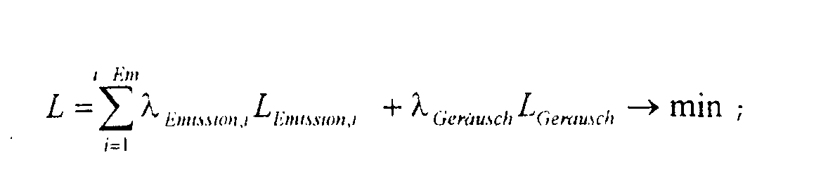
Die Gewichtungsfaktoren γ Moment , γ eta sowie λ Emissionn,i und λGeräusch werden unter Berücksichtigung des Fahrertyps und der Fahrsituation adaptiv festgelegt. So erhält für einen ökonomischen Fahrer die Größe Geta besonderes Gewicht, indem der Gewichtungsfaktor γ eta entsprechend gewählt wird. Bei Stadtfahrten werden Emissionsgesichtspunkte, die durch die Größen LEmission,i quantifiziert werden, verstärkt berücksichtigt, indem die Gewichtungsfaktoren λ Emissionn,i entsprechend gewählt werden. Ist beispielsweise die Fahrsituation "slow and go" in einer verkehrsberuhigten Zone erkannt, so findet der Term LGeräusch durch geeignete Wahl von λ Geräusch besondere Berücksichtigung. Weiterhin werden auch bei der Berechnung der Terme GMoment , Geta , LEmission,i und LGeräusch Fahrertyp und Fahrsituation in applizierbarer Weise berücksichtigt. Die Berechnungsvorschriften für die Größen GMoment , Geta , LEmission,i und LGeräusch werden im folgenden beschrieben.The weighting factors γ moment , γ eta and λ emissions, i and λ noise are adaptively determined taking into account the driver type and the driving situation. For an economic driver, the size G eta is given special weight by selecting the weighting factor γ eta accordingly. When driving in cities, emissions considerations that are quantified by the quantities L emission, i are taken into account to a greater extent by selecting the weighting factors λ emissions, i accordingly. If, for example, the driving situation "slow and go" is recognized in a traffic-calmed zone, the term L noise is given special consideration by a suitable choice of λ noise . Furthermore, when calculating the terms G moment , G eta , L emission, i and L noise, driver type and driving situation are taken into account in an applicable manner. The calculation rules for the quantities G moment , G eta , L emission, i and L noise are described below.
Die Ermittlung einer den Fahrertyp repräsentierenden Größe aFahrer beziehungsweise von Größen, die die momentan vorliegenden Fahrsituation beschreiben, ist in dem eingangs aufgeführten Stand der Technik detailliert beschrieben.The determination of a size a driver representing the driver type or of sizes that describe the current driving situation is described in detail in the prior art mentioned at the beginning.
Die Größe GMoment bewertet die Momentenreserve Δmd_ga, die bei
einem geforderten Getriebeausgangsmoment md_ga_soll (Block
201, Fig.2, Verlauf 32 in der Fig.3) bei gegebener Getriebeausgangsdrehzahl
n_ga für ein Wertepaar (u, n_mot) aus
Getriebeübersetzung und Motordrehzahl am Getriebeausgang zur
Verfügung steht. Die Größe GMoment wird wie folgt berechnet:The magnitude G torque evaluates the torque reserve Δmd_ga, which, for a required transmission output torque md_ga_soll (block 201, FIG. 2,
Die Momentenübersetzung mue_ges des Antriebsstrangs ergibt
sich als Funktion der Getriebeübersetzung u, der Motordrehzahl
n_mot, des momentanen Drehzahlverhältnisses ν Wandler des
hydrodynamischen Drehmomentwandlers 103 und dem Zustand
ZWandler der Wandlerüberbrückungskupplung 104:
Im Falle der Verwendung einer Trockenreibkupplung statt des
hydrodynamischen Drehmomentwandlers 103 beschreibt die Größe
ν Wandler ebenfalls das Drehzahlverhältnis an der Kupplung, der
Zustand ZWandler gibt in diesem Fall den Zustand (offen,
schleifend, geschlossen) der Trockenreibkupplung an. Der Zustand
"schleifend" kann sowohl im Falle einer Wandlerüberbrückungskupplung
als auch im Falle einer Trockenreibkupplung
auch numerisch durch das übertragene Moment beschrieben
werden. If a dry friction clutch is used instead of the
Das am Motorausgang für die Motordrehzahl n_mot maximal bereitstellbaren
Moment md_ma_max_n ergibt sich zu:
Der Verlauf dieser sogenannten Vollastlinie ist mit dem Verlauf
31 in der Figur 3 beispielhaft zu sehen. Bei der Berechnung
werden die aktuellen Betriebsbedingungen des Motors wie
z.B. Motortemperatur und Umgebungseinflüsse (z.B. Luftdichteänderungen
bei einer Fahrt in großer Höhe) sowie die Randbedingungen,
unter denen das Moment realisiert wird, berücksichtigt.
Randbedingung ist z.B. eine erlaubte oder nicht zugelassene
Vollastanreicherung des Motors.The course of this so-called full load line is with the
Das bei einer bestimmten Motordrehzahl n_mot maximal bereitstellbare
Moment md_ga_max_n am Getriebeausgang für die berechnete
Momentenübersetzung mue_ges ergibt somit zu:
Die Momentenreserve Δmd_ga am Getriebeausgang ergibt sich
somit zu:
Zur Normierung der Momentenreserve wird die Größe Δmd_ga in
Relation gesetzt zur maximal möglichen Momentenreserve
Δmd_ga_pot, die bei der momentane Getriebeausgangsdrehzahl
n_ga und dem geforderten Getriebeausgangsmoment md_ga_soll
möglich ist. Der Motor erzielt bei der Drehzahl n_pot die maximale
Ausgangsleistung und stellt dabei am Motorausgang das
Moment md_ma_pot zur Verfügung. Für die Getriebeausgangsdrehzahl
n_ga wird das maximal mögliche Getriebeausgangsmoment
md_ga_pot ermittelt zu:

Eine mögliche Wandlerverstärkung wird dabei zu mue_wandler = 1
angenommen. Die maximal mögliche Momentenreserve wird dann bestimmt
zu:
Die normierte Momentenreserve am Getriebeausgang wird damit
bestimmt zu:
Für n_mot = n_pot ist Δmd_ga_norm=1; für eine verschwindende Momentenreserve ist Δmd_ga_norm=0. Kann das geforderte Getriebeausgangsmoment bei der Motordrehzahl n_mot nicht eingestellt werden, ergibt sich ein negativer Wert für Δmd_ga_norm .For n_mot = n_pot , Δ md_ga_norm = 1; for a vanishing torque reserve, Δmd_ga_norm = 0. If the required transmission output torque can not be set at engine speed n_mot , the result is a negative value for Δmd_ga_norm .
Beispielhaft sind in der Figur 3 zwei Situationen für Motordrehzahlen n_mot 1 und n_mot 2 dargestellt. Für die Motordrehzahl n_mot 1 ergibt sich ein negativer Wert für die normierte Momentenreserve am Getriebeausgang, angedeutet durch einen negativen gerichteten Pfeil. Für die Motordrehzahl n_mot 2 ergibt sich ein positiver Wert für die normierte Momentenreserve am Getriebeausgang, angedeutet durch einen positiven gerichteten Pfeil.For example, two situations for engine speeds n_mot 1 and n_mot 2 are shown in FIG . For the engine speed n_mot 1 there is a negative value for the normalized torque reserve at the transmission output, indicated by a negative directional arrow. For the engine speed n_mot 2 there is a positive value for the normalized torque reserve at the transmission output, indicated by a positive directional arrow.
Zur fahrertypspezifischen Bestimmung der gewünschten normierten
Momentenreserve Δmd_ga_norm_opt wird der Fahrertyp durch
die Größe aFahrer beschrieben, wobei 0 ≤ aFahrer ≤ 1. Der Größe aFahrer
wird durch eine Funktion mMoment(aFahrer) eine gewünschte
normierte Momentenreserve Δmd_ga_norm_opt zugeordnet:
Die Größe GMoment soll einen maximalen Beitrag zur Zielfunktion
G liefern, wenn die normierte Momentenreserve mit der normierten
gewünschten Momentenreserve übereinstimmt. Dieser maximale
Beitrag wird zu 1 skaliert. Bei verschwindender Momentenreserve
soll der Beitrag 0 sein, bei negativer normierter
Momentenreserve soll ein hoher negativer Strafbeitrag erfolgen.
Die Größe GMoment wird dazu mittels einer Funktion
gMoment (Δmd_ga_norm,Δmd_ga_norm_opt) ist in der Figur 5 dargestellt. g moment (Δ md_ga_norm, Δmd_ga_norm_opt ) is shown in FIG. 5.
Somit ist die Bewertungsgröße GMoment für die Momentenreserve bestimmt.The evaluation variable G torque is thus determined for the torque reserve.
Die Größe Geta beschreibt den Gesamtwirkungsgrad des Antriebsstrangs und bewegt sich im Intervall [0, 1].The size G eta describes the overall efficiency of the drive train and moves in the interval [0, 1].
Erreichen die Komponenten Motor 101, Wandler 103 und Getriebe
106 gleichzeitig ihren absoluten optimalen Wirkungsgrad, so
ist Geta =1. Zur Bestimmung von Geta werden die erforderlichen
Größen zur Kennzeichnung des Wirkungsgrades von Motor 101,
Wandler 103 und Getriebe 106 wie folgt berechnet:If the components motor 101,
Die Größe GM,eta zur Beschreibung des Motor-Wirkungsgrades ergibt
sich zu:
Dabei ist be (md_ma,n_mot) der spezifische Kraftstoffverbrauch beim Motorausgangsmoment md_ma und der Motordrehzahl n_mot. Der minimal mögliche spezifische Kraftstoffverbrauch, mit dem die Motorausgangsleistung md_ma·n_mot realisiert werden kann, ist b min / e(md_ma·n_mot).Here b e ( md_ma, n_mot ) is the specific fuel consumption at the engine output torque md_ma and the engine speed n_mot . The minimum possible specific fuel consumption with which the engine output md_ma · n_mot can be realized is b min / e ( md_ma · n_mot ).
Die Größe GM,eta wird 1, wenn der Motor an dem für die geforderte Motorleistung verbrauchsgünstigsten Betriebspunkt arbeitet und wird für ungünstige Betriebspunkte kleiner. Die Größe GM,eta bewegt sich somit im Intervall [0, 1].The size G M, eta becomes 1 when the engine is operating at the most economical operating point for the required engine power and becomes smaller for unfavorable operating points. The size G M, eta thus moves in the interval [0, 1].
Die Größe GG,eta zur Beschreibung des Getriebe-Wirkungsgrades
ergibt sich zu:
Dabei ist η G (u,n_ga,md_ga) der Wirkungsgrad, mit dem das Getriebe das Ausgangsmoment md_ga bei einer Drehzahlübersetzung von u und einer Ausgangsdrehzahl von n_ga abgibt. Der maximale Wirkungsgrad des Getriebes über den gesamten Betriebsbereich ist η max / G. Die Größe GM,eta bewegt sich im Intervall [0, 1]. Here, η G ( u, n_ga, md_ga ) is the efficiency with which the transmission delivers the output torque md_ga at a speed ratio of u and an output speed of n_ga . The maximum efficiency of the transmission over the entire operating range is η max / G. The size G M, eta is in the interval [0, 1].
Die Größe GW,eta zur Beschreibung des Wirkungsgrades des
Drehmomentwandlers ergibt sich zu:
Die Größe GW , eta bewegt sich ebenfalls im Intervall [0, 1].The size G W , eta is also in the interval [0, 1].
Die Bewertungsgröße Geta für den Gesamtwirkungsgrad des
Antriebsstrangs ist dann:
Die Größe LEmission,i beschreibt das Emissionsverhalten für die Schadstoffkomponente i. Relevante Schadstoffkomponenten, für die LEmission,i zu ermitteln ist , sind z.B. NOx, CO und HC.The size L emission, i describes the emission behavior for the pollutant component i . Relevant pollutant components for which L emission, i is to be determined are, for example, NO x , CO and HC.
Die Ermittlung erfolgt nach folgender Berechnungsvorschrift:The calculation is based on the following calculation rule:
Dabei ist ci (md_ma,n_mot) die spezifische Emission (z.B. in g/kWh) für die Schadstoffkomponente i beim Motorausgangsmoment md_ma und der Drehzahl n_mot. Die minimal mögliche spezifische Emission, mit der die Motorausgangsleistung md_ma·n_mot realisiert werden kann, ist c min / i(md_ma,n_mot). Die Größe lEmission,i wird 1, wenn der Motor an dem für die geforderte Motorleistung und für die Schadstoffkomponente i emissionsgünstigsten Betriebspunkt arbeitet und wird für ungünstige Betriebspunkte größer.Here c i ( md_ma, n_mot ) is the specific emission (for example in g / kWh) for the pollutant component i at the engine output torque md_ma and the speed n_mot . The minimum possible specific emission with which the engine output md_ma · n_mot can be realized is c min / i ( md_ma, n_mot ). The quantity l emission, i becomes 1 if the engine is working at the most favorable operating point for the required engine power and for the pollutant component i and becomes larger for unfavorable operating points.
Zur Berechnung von LEmission,i aus lEmission,i sind wahlweise zwei applizierbare alternative Berechnungsmöglichkeiten heranzuziehen:To apply L emission, i from l emission, i , two applicable alternative calculation options can be used:
1.2.3.2 Nichtlineare Gewichtung von lEmission,i mittels einer
Barriere-Methode. Dabei wird das Überschreiten eines applizierbaren
Grenzwertes l grenz / Emission,idurch einen besonders hohen Beitrag
zur Größe LEmission,i bewertet, wobei Emissionswerte unterhalb
des Grenzwertes keinen Beitrag liefern:

Damit ist die Bewertungsgröße LEmission,i für das Emissionsverhalten bezüglich der Schadstoffkomponente i bestimmt.The evaluation variable L emission, i is thus determined for the emission behavior with regard to the pollutant component i .
Die Größe LGeräusch beschreibt das Schallemissionsverhalten des
gesamten Anriebstrangs. Sie wird für den Arbeitspunkt des
Antriebsstrangs aus Beschreibungsgrößen für die Schallemission
des Motors 101 und des Getriebes 106 ermittelt zu:
Durch die im folgenden beschriebene Rechenvorschrift wird eine
Näherungslösung ![]()
![]()
Im Schritt 601 werden, wie schon beschrieben, die Gewichtungsfaktoren
γ Moment , γ eta , λEmissionn,i und λGeräusch bestimmtAs already described, the weighting factors γ moment , γ eta , λ emissions, i and λ noise are determined in
Die Bestimmung der Näherungslösung
Der Wert von F wird für den aktuellen Arbeitspunkt x des
Antriebsstrangs ermittelt. Der aktuelle Arbeitspunkt x wird
durch

Der Wert von F wird für I weitere, mögliche Arbeitspunkte
x i (i=1,...,I) des Antriebsstrangs ermittelt, für die das aktuelle
Getriebeausgangsmoment md_ga bei der Getriebeausgangsdrehzahl
n_ga realisiert werden kann. Diese Arbeitspunkte ergeben sich
durch Variation der Motordrehzahl:
Die Drehzahlen n_moti werden nach folgender Berechnungsvorschrift
bestimmt:
Bei der Ermittlung der Größen n_moti werden die obenbeschriebenen expliziten und impliziten Restriktionen des Optimierungsproblems berücksichtigt. Die Funktionen si können dabei auch Wissen über die Antriebsstrangkomponenten enthalten, wie z.B. die diskreten Übersetzungsstufen bei Stufengetrieben. Die Anzahl I der zu untersuchenden Arbeitspunkte kann dynamisch variiert werden.When determining the variables n_mot i , the explicit and implicit restrictions of the optimization problem described above are taken into account. The functions s i can also contain knowledge about the drive train components, such as the discrete gear ratios in multi-step transmissions. The number I of the working points to be examined can be varied dynamically.
Die Bestimmung der Arbeitspunkte

Die so ermittelten Arbeitspunkte x i liegen auf der durch den Getriebewirkungsgrad korrigierten Leistungshyperbel im Motorkennfeld, auf der auch der Arbeitspunkt x liegt.The working points x i determined in this way lie on the power hyperbola in the engine map corrected by the transmission efficiency, on which the working point x also lies.
Die Ermittlung der Werte Fi für die Arbeitspunkte x i ,i = 1,...,I
geschieht gemäß der Rechenvorschrift:
Die Näherungslösung ![]()
![]()
Der zugehörige optimale Arbeitspunkt des Triebstrangs
ist x opt = x k . Er wird bei der Motordrehzahl
Unter Berücksichtigung des durch die Lösung des Optimierungsproblems ermittelten Vorschlags für einen optimalen Arbeitspunkt x opt des Antriebsstrangs werden durch eine koordinierte Antriebsstrangsteuerung Vorgaben für das Motorausgangsmoment md_ma_soll und die Getriebeübersetzung u_soll ermittelt. Die schon beschriebene Figur 2 zeigt die Grundstruktur einer koordinierten Antriebsstrangsteuerung zur Realisierung des vom Fahrer geforderten Getriebeausgangsmomentes md_ga_soll.Taking into account the proposal for an optimal operating point x opt of the drive train determined by the solution of the optimization problem, specifications for the engine output torque md_ma_soll and the gear ratio u_soll are determined by a coordinated drive train control. FIG. 2, which has already been described, shows the basic structure of a coordinated drive train control for realizing the transmission output torque md_ga_soll required by the driver.
Die Vorgaben für md_ma_soll und u_soll werden aus dem im
Schritt 607 ermittelten optimalen Arbeitspunkt x opt des
Antriebsstrangs bestimmt zu:
Es wird also die Übersetzung u_soll am Getriebe eingestellt, die durch den optimalen Arbeitspunkt x opt des Antriebsstrangs vorgegeben wird.The gear ratio u_soll is therefore set on the gearbox, which is predetermined by the optimal operating point x opt of the drive train.
Die erfindungsgemäße Vorgehensweise bietet vorteilhafterweise die Möglichkeit, den Fahrerwunsch unter Berücksichtigung mehrerer Kriterien optimal realisieren zu können.The procedure according to the invention advantageously offers the possibility of considering the driver's request to be able to optimally implement several criteria.
Die Kriterien werden dabei basierend auf physikalischen Größen für den Gesamtwirkungsgrad des Antriebsstrangs, die Momentenreserve am Getriebeausgang, sowie Schadstoff- und Schallemissionen systematisch berücksichtigt. Dadurch wird ein Arbeitspunkt des Triebstrangs ermittelt, der sowohl unterschiedlichen Fahrsituationen und Fahrertypen als auch Anforderungen an Schadstoff- und Schallemissionen gerecht wird. Die Gewichtung der relevanten Kriterien kann während des Fahrbetriebs adaptiv verändert werden. The criteria are based on physical quantities for the overall efficiency of the drive train, the torque reserve at the gearbox output, as well as pollutant and noise emissions systematically taken into account. This will create a Operating point of the drive train determined, both different Driving situations and driver types as well as requirements in pollution and noise emissions. The Weighting of the relevant criteria can be done while driving be changed adaptively.
Die Ermittlung des optimalen Arbeitspunktes erfolgt modellbasiert, ausgehend von physikalischen Beschreibungsgrößen für Motor- und Getriebeeigenschaften.The optimal working point is determined based on the model, based on physical description quantities for Engine and transmission properties.
Eine Applikation von Kenngrößen, die von der speziellen Motor-Getriebekombination abhängig sind, ist somit nicht erforderlich.An application of parameters based on the special motor-gear combination are therefore not necessary.
Weiterhin werden dadurch vom Normalbetrieb abweichende Betriebsbedingungen von Motor und Getriebe bei der Ermittlung des optimalen Arbeitspunktes durch das erfindungsgemäße Verfahren systematisch berücksichtigt. This also means that operating conditions deviate from normal operation of engine and transmission in the determination the optimal working point by the inventive method systematically taken into account.
- md_mamd_ma
- MotorausgangsmomentEngine output torque
- md_ma_sollmd_ma_soll
- Sollwert für das MotorausgangsmomentSetpoint for the engine output torque
- md_gamd_ga
- GetriebeausgangsmomentTransmission output torque
- md_ga_sollmd_ga_soll
- Sollwert für das GetriebeausgangsmomentSetpoint for the transmission output torque
- D md_gaD md_ga
- Momentenreserve am GetriebeausgangTorque reserve at the transmission output
- n_gan_ga
- GetriebeausgangsdrehzahlTransmission output speed
- n_motn_mot
- MotordrehzahlEngine speed
- n_mot_minn_mot_min
- minimal zulässige Motordrehzahlminimum permissible engine speed
- n_mot_maxn_mot_max
- maximal zulässige Motordrehzahlmaximum permissible engine speed
- uu
- Drehzahlübersetzung des GetriebesSpeed ratio of the transmission
- u_minU_min
- minimal einstellbare Getriebeübersetzungminimally adjustable gear ratio
- u_maxu_max
- maximal einstellbare Getriebeübersetzungmaximum adjustable gear ratio
- mue_gesmue_ges
- Momentenübersetzung des AntriebsstrangsTorque transmission of the drive train
- ν Wandler ν converter
-
Drehzahlverhältnis des (hydrodynamischen) Drehmomentwandlers
n_wa: Wandlerausgangsdrehzahl
n_we: WandlereingangsdrehzahlSpeed ratio of the (hydrodynamic) torque converter
n _ wa : converter output speed
n_we : converter input speed - ZWandler Z converter
- Zustand der Wandlerüberbrückungskupplung beziehungsweise der KupplungCondition of the converter lock-up clutch or the clutch
- αα
- Stellung des FahrpedalsPosition of the accelerator pedal
- aFahrer a driver
- Größe zur Beschreibung des FahrertypsSize to describe the driver type
- γ Moment , γ eta γ moment , γ eta
- Gewichtungsfaktorenweighting factors
- λEmissionn,i , λGeräusch λ emissions, i , λ noise
- Gewichtungsfaktorenweighting factors
- md_ma_maxmd_ma_max
- maximal bereitstellbares Motormomentmaximum available engine torque
- md_ma_max_nmd_ma_max_n
- am Motorausgang für die Motordrehzahl n_mot maximal bereitstellbares Motormoment the engine output for the engine speed n_mot maximum deployable engine torque
- md_ga_max_nmd_ga_max_n
- maximal bereitstellbaren Moment am Getriebeausgang für die Motordrehzahl n_mot maximum available torque at the transmission output for the engine speed n_mot
- GMoment G wait
- Bewertungsgröße für die MomentenreserveEvaluation size for the torque reserve
- Geta G eta
- Bewertungsgröße für den Gesamtwirkungsgrad des AntriebsstrangsAssessment variable for the overall efficiency of the powertrain
- GM,eta G M, eta
- Bewertungsgröße zur Beschreibung des Motor-WirkungsgradesEvaluation quantity to describe the motor efficiency
- GG,eta G G, eta
- Bewertungsgröße zur Beschreibung des Getriebe-WirkungsgradesEvaluation quantity to describe the gearbox efficiency
- GW,eta G W, eta
- Bewertungsgröße zur Beschreibung des Wirkungsgrades des DrehmomentwandlersEvaluation quantity to describe the efficiency of the torque converter
- LEmission,i L emission, i
- Bewertungsgröße zur Beschreibung des Emissionsverhaltens für die Schadstoffkomponente iAssessment quantity to describe the emission behavior for the pollutant component i
- LGeräusch L noise
- Bewertungsgrößezur Beschreibung des Schallemissionsverhaltens des gesamten AntriebsstrangsEvaluation quantity for the description of the sound emission behavior of the entire powertrain
- XX
- aktueller Arbeitspunkt des Antriebsstrangscurrent operating point of the drive train
Claims (12)
- Method for controlling the drive train of a motor vehicle having at least one drive unit which has an adjustable output torque (md_ma) and an output speed (n_mot), and a gearbox which is arranged between the drive unit and the wheels of the motor vehicle and has an output torque (md_ga) and whose rotational speed transmission ratio (u) is adjustable, a set-point value (md_ga_setp) being predefined for the gearbox output torque, in particular as a function of the sensed position of an accelerator pedal which can be activated by the driver of the motor vehicle, and different operating points (xi ) of the drive train are characterized by at least different output torques (md_mai ) of the drive unit and rotational speed transmission ratios (u i) and/or different output speeds (n_moti ) of the drive unit, characterized in that during the driving modein each case a set of evaluation variables (GTorque, Geta, LEmission,i, LNoise ) is emitted for possible operating points (xi ), andthe evaluation variables (GTorque , Geta, LEmission,i, LNoise ) which are associated with a set are logically linked by means of an optimization method and the operating point at which the logic linking result (F) which is dependent on the predefined set-point value (md_ga_setp) for the gearbox output torque assumes an extreme value is used to select one of the possible operating points as an optimum operating point (xopt ), andthe gearbox transmission ratio (uopt ) which is associated with the selected operating point (xopt ) and/or the output speed (n_mot), associated with the selected operating point (xopt ), of the drive unit is set.
- Method for controlling the drive train of a motor vehicle having at least one drive unit which has an adjustable output torque (md_ma) and an output speed (n_mot), and a gearbox which is arranged between the drive unit and the wheels of the motor vehicle and has an output torque (md_ga) and whose rotational speed transmission ratio (u) is adjustable, a set-point value (md_ga_setp) for the gearbox output torque being predefined as a function of the sensed position of an accelerator pedal which can be activated by the driver of the motor vehicle, and different operating points (xi ) of the drive train are characterized by at least different output torques (md_mai ) of the drive unit and rotational speed transmission ratios (ui ) and/or different output torques (n_moti ) of the drive unit, characterized in that during the driving modein each case a set of evaluation variables (GTorque, Geta, LEmission,i, LNoise ) being determined for possible operating points (xi ), the following being determined as evaluation variables: at leastone first value (GTorque ) which represents the reserve of the gearbox output torque and/orone second value (Geta ) which represents the overall efficiency of the drive train of the vehicle, and/orone third value (LEmission,i ) which represents the emission behaviour of different pollutant components (i), and/orone fourth value (LNoise ) which represents the sound emission, andone of the possible operating points is selected as an optimum operating point (xopt ) by means of an optimization method based on the evaluation variables which are determined, andthe gearbox transmission ratio (uopt ) which is associated with the selected operating point (xopt ) and/or the output speed (n_mot), which is associated with the selected operating point (xopt ) of the drive unit is selected.
- Method according to Claim 2, characterized in that the optimization method is carried out in such a way that the evaluation variables (GTorque , Geta , LEmission,i, LNoise ) which are associated with a set are logically linked and the operating point at which the logic linking result (F) assumes an extreme value is used to select the optimum operating point (xopt ).
- Method according to Claim 1 or 3, characterized in that the evaluation variables (GTorque, Geta, LEmission,i, LNoise ) which are associated with a set are weighted and the weighted evaluation variables are logically linked to form the logic linking result (F).
- Method according to Claim 1 or 2, characterized in that the optimization method is carried out in such a way that the evaluation variables (GTorque , Geta, LEmission,i, LNoise ) which are associated with a set are logically linked to form a weighted sum (F) and the operating point at which the weighted sum (F) assumes an extreme value is used to select the optimum operating point (xopt ).
- Method according to Claim 1 or 2, characterized in that a variable which represents the driving behaviour of the driver of the motor vehicle, a variable which represents the instantaneous driving situation of the motor vehicle and/or a variable which represents the instantaneous ambient influences acting on the vehicle are determined and at least one of these variables which are determined is taken into account in the determination of the evaluation variables (GTorque, Geta, LEmission,i, LNoise ) and/or in the selection of the optimum operating point (xopt ).
- Method according to Claim 4, characterized in that a variable which represents the driving behaviour of the driver of the motor vehicle, a variable which represents the instantaneous driving situation of the motor vehicle and/or a variable which represents the instantaneous ambient influences acting on the motor vehicle are determined and at least one these variables which are determined is used to weight the evaluation variables.
- Method according to Claim 1, characterized in that the following are used as evaluation variables: at leastone first value (GTorque ) which represents the reserve of the gearbox output torque, and/orone second value (Geta ) which represents the overall efficiency of the drive train of the vehicle, and/orone third value (LEmission,i ) which represents the emission behaviour of different pollutant components (i), and/orone fourth value (LNoise ) which represents the sound emission.
- Device for controlling the drive train of a motor vehicle having at least one drive unit which has an adjustable output torque (md_ma) and an output torque (n_mot), and a gearbox which is arranged between the drive unit and the wheels of the motor vehicle and has an output torque (md_ga) and whose rotational speed transmission ratio (u) is adjustable, different operating points (xi ) of the drive train being characterized by at least different output torques (md_mai ) of the drive unit and rotational speed transmission ratios (ui ) and/or different output speeds (n_moti ) of the drive unit, characterized in that means are provided with which, during the driving modein each case a set of evaluation variables (GTorque, Geta, LEmission,i, LNoise ) is determined for possible operating points (xi ), andthe evaluation variables (GTorque , Geta, LEmission,i, LNoise ) which are associated with a set are logically linked by means of an optimization method and the operating point at which the logic linking result (F) which is dependent on the predefined set-point value (md_ga_setp) for the gearbox output torque assumes an extreme value is used to select one of the possible operating points as an optimum operating point (xopt ), andthe gearbox transmission ratio (uopt ) which is associated with the selected operating point (xopt ) and/or the output speed (n_mot), which is associated with the selected operating point (xopt ), of the drive unit is set.
- Device for controlling the drive train of a motor vehicle having at least one drive unit which has an adjustable output torque (md_ma) and an output speed (n_mot) and a gearbox which is arranged between the drive unit and the wheels of the motor vehicle and has an output torque (md_ga) and whose rotational speed transmission ratio (u) is adjustable, different operating points (xi ) of the drive train being characterized by at least different output torques (md_mai ) of the drive unit and rotational speed transmission ratios (ui ) and/or different output speeds (n_moti ) of the drive unit, characterized in that means are provided with which, during the driving modein each case a set of evaluation variables (GTorque, Geta, LEmission,i, LNoise ) is determined for possible operating points (xi ), the following being determined as evaluation variables: at leastone first value (GTorque ) which represents the reserve of the gearbox output torque and/orone second value (Geta ) which represents the overall efficiency of the drive train of the vehicle, and/orone third value (LEmission,i ) which represents the emission behaviour of different pollutant components (i), and/orone fourth value (LNoise ) which represents the sound emission, andone of the possible operating points is selected as an optimum operating point (xopt ) by means of an optimization method based on the evaluation variables which are determined, andthe gearbox transmission ratio (uopt ) which is associated with the selected operating point (xopt ) and/or the output speed (n_mot), which is associated with the selected operating point (xopt ) of the drive unit is selected.
- Device according to Claim 10, characterized in that the optimization method is carried out in such a way that the evaluation variables (GTorque, Geta, LEmission,i, LNoise ) which are associated with a set are logically linked and the operating point at which the logic linking result (F) assumes an extreme value is used to select the optimum operating point (xopt ).
- Device according to Claim 11, characterized in that the evaluation variables (GTorque, Geta, LEmission,i, LNoise ) which are associated with a set are weighted and the weighted evaluation variables are logically linked to form the logic linking result(F).
Applications Claiming Priority (3)
| Application Number | Priority Date | Filing Date | Title |
|---|---|---|---|
| DE19703863A DE19703863A1 (en) | 1997-02-03 | 1997-02-03 | Method and device for controlling the drive train of a motor vehicle |
| DE19703863 | 1997-02-03 | ||
| PCT/DE1998/000120 WO1998033673A1 (en) | 1997-02-03 | 1998-01-15 | Method and device for controlling the drive train of a motor vehicle |
Publications (2)
| Publication Number | Publication Date |
|---|---|
| EP0907524A1 EP0907524A1 (en) | 1999-04-14 |
| EP0907524B1 true EP0907524B1 (en) | 2003-11-05 |
Family
ID=7819075
Family Applications (1)
| Application Number | Title | Priority Date | Filing Date |
|---|---|---|---|
| EP98907816A Expired - Lifetime EP0907524B1 (en) | 1997-02-03 | 1998-01-15 | Method and device for controlling the drive train of a motor vehicle |
Country Status (7)
| Country | Link |
|---|---|
| US (1) | US6154701A (en) |
| EP (1) | EP0907524B1 (en) |
| JP (1) | JP2000509676A (en) |
| KR (1) | KR100611023B1 (en) |
| CZ (1) | CZ316098A3 (en) |
| DE (2) | DE19703863A1 (en) |
| WO (1) | WO1998033673A1 (en) |
Families Citing this family (41)
| Publication number | Priority date | Publication date | Assignee | Title |
|---|---|---|---|---|
| ES2221450T3 (en) * | 1998-10-21 | 2004-12-16 | Robert Bosch Gmbh | DEVICE AND PROCEDURE FOR THE COORDINATED CONTROL OF THE TRANSMISSION TRAIN OF A VEHICLE DURING THE CHANGE CHANGING PROCESSES. |
| DE19858584B4 (en) * | 1998-12-18 | 2007-12-27 | Robert Bosch Gmbh | Method and device for controlling a drive unit of a vehicle |
| US6263269B1 (en) * | 1998-12-23 | 2001-07-17 | International Truck And Engine Corporation | Configuration programming of input/output connections for network modules in a multiplexed vehicle communication system |
| DE19938623C2 (en) * | 1999-08-14 | 2001-09-06 | Daimler Chrysler Ag | System for minimizing the power dissipation equivalents of a drive system |
| DE19940703C1 (en) | 1999-08-27 | 2001-05-10 | Bayerische Motoren Werke Ag | Method and device for engine and transmission control in a motor vehicle |
| DE19948157A1 (en) * | 1999-10-07 | 2001-05-10 | Volkswagen Ag | Method and device for damping shift jerks in a motor vehicle |
| DE19962962A1 (en) * | 1999-12-24 | 2001-06-28 | Bosch Gmbh Robert | Determining gear selection of discrete switching vehicle gearbox involves changing up if up shift threshold exceeded or down if optimum engine speed exceeded above down shift threshold |
| DE19963564A1 (en) * | 1999-12-29 | 2001-07-05 | Bosch Gmbh Robert | System for setting a transmission ratio in a transmission installed in a motor vehicle |
| DE10023053A1 (en) * | 2000-05-11 | 2001-12-13 | Zahnradfabrik Friedrichshafen | Control system for a motor vehicle transmission with a torque converter or a hydrodynamic clutch |
| WO2002012013A1 (en) | 2000-08-10 | 2002-02-14 | Robert Bosch Gmbh | Method and device for controlling the drivetrain of a motor vehicle during gearshift operations |
| FR2827339B1 (en) * | 2001-07-12 | 2005-11-11 | Renault | DEVICE FOR CONTROLLING THE OPERATING POINT OF THE POWER UNIT OF A VEHICLE |
| DE10160480A1 (en) | 2001-12-08 | 2003-06-26 | Bosch Gmbh Robert | Method and appliance for coordinated control of mechanical, electrical and thermal power flow in motor vehicle by optimizing desired power requirements based on actual power outputs |
| US6671603B2 (en) | 2001-12-21 | 2003-12-30 | Daimlerchrysler Corporation | Efficiency-based engine, powertrain and vehicle control |
| DE10221341B4 (en) * | 2002-05-08 | 2015-03-26 | Robert Bosch Gmbh | Method and device for controlling the drive unit of a vehicle |
| DE10225448A1 (en) * | 2002-06-08 | 2003-12-18 | Bosch Gmbh Robert | Method and device for controlling the internal combustion engine of a vehicle |
| FR2840958B1 (en) * | 2002-06-13 | 2007-03-09 | Renault Sa | METHOD FOR CONTROLLING THE OPERATION OF A MOTOR POWER GROUP AND DEVICE IMPLEMENTING THE METHOD |
| DE10347596B3 (en) * | 2003-10-14 | 2005-06-02 | Bayerische Motoren Werke Ag | Operating efficiency optimization method for automobile hybrid drive system with measurement of actual operating efficiency of each drive unit at each operating point and re-setting of operating point upon variation in monitored parameter |
| US7110871B2 (en) * | 2003-10-14 | 2006-09-19 | General Motors Corporation | Method for determining preferred input operating points for a vehicle transmission |
| US6957137B2 (en) * | 2003-10-14 | 2005-10-18 | General Motors Corporation | Real-time operating parameter selection in a vehicular transmission |
| US7200476B2 (en) * | 2003-10-14 | 2007-04-03 | General Motors Corporation | Optimal selection of input torque considering battery utilization for a hybrid electric vehicle |
| JP4857518B2 (en) | 2003-12-24 | 2012-01-18 | トヨタ自動車株式会社 | Vehicle control device |
| DE102004022114B4 (en) | 2004-05-05 | 2018-11-22 | Robert Bosch Gmbh | Method for operating a vehicle |
| FR2870911B1 (en) * | 2004-05-28 | 2007-08-31 | Renault Sas | METHOD FOR CONTROLLING AN AUTOMATED TRANSMISSION FOR A MOTOR VEHICLE BASED ON AUTOMATIC OR MANUAL DRIVING MODES WITH IMPULSE CONTROL AND CORRESPONDING DEVICE |
| FR2873642B1 (en) * | 2004-07-27 | 2007-02-16 | Renault Sas | DEVICE FOR CONTROLLING AN AUTOMATED TRANSMISSION FOR MOTOR PROPELLER GROUP OF A MOTOR VEHICLE, AND ASSOCIATED METHOD |
| DE102004039272A1 (en) * | 2004-08-13 | 2006-02-23 | Zf Friedrichshafen Ag | Method for determining a transmission ratio in the drive train of a motor vehicle |
| FR2875203B1 (en) * | 2004-09-10 | 2006-12-01 | Renault Sas | METHOD FOR PRODUCING A SET FOR IMPROVING THE DRIVING APPROVAL FOR A DEVICE FOR TRANSMITTING A MOTOR VEHICLE MOTOR PUSH GROUP AND CORRESPONDING DEVICE |
| DE102005012255A1 (en) * | 2005-03-17 | 2006-09-21 | Zf Friedrichshafen Ag | Method for controlling a controllable aggregate |
| DE102006017712A1 (en) | 2006-04-15 | 2007-10-25 | Zf Friedrichshafen Ag | Method for switching control of an automated stepped gearbox |
| US8200403B2 (en) * | 2007-11-02 | 2012-06-12 | GM Global Technology Operations LLC | Method for controlling input torque provided to a transmission |
| DE102008018969A1 (en) * | 2008-04-16 | 2009-01-22 | Daimler Ag | Method for controlling of switch operation involves 3 phases managing the engine moment |
| IT1399015B1 (en) * | 2009-02-13 | 2013-04-05 | Magneti Marelli Spa | METHOD OF IDENTIFYING THE OPTIMAL GEAR FOR A VEHICLE TRANSMISSION |
| DE102010008695A1 (en) | 2010-02-19 | 2011-08-25 | FEV Motorentechnik GmbH, 52078 | Method for controlling operating point of hybrid drive system of vehicle, involves calculating cost function of basic concept of optimization criterion corresponding to driver desire torque |
| DE102011075913A1 (en) * | 2011-05-16 | 2012-11-22 | Zf Friedrichshafen Ag | Method for determining a switching sequence of a ratio change of a transmission device of a vehicle drive train |
| KR101713924B1 (en) | 2012-10-02 | 2017-03-08 | 스카니아 씨브이 악티에볼라그 | Regulation of concentration/fraction of substances in an exhaust stream |
| KR101713925B1 (en) | 2012-10-02 | 2017-03-08 | 스카니아 씨브이 악티에볼라그 | Regulation of concentration/fraction of substances in an exhaust stream |
| GB2517430B (en) * | 2013-08-19 | 2016-02-10 | Jaguar Land Rover Ltd | Selection of launch ratio in a multi-speed automatic transmission |
| DE102014005398A1 (en) * | 2014-04-11 | 2015-10-15 | Avl List Gmbh | Method for evaluating the switching behavior of a motor vehicle transmission |
| WO2017095426A1 (en) * | 2015-12-03 | 2017-06-08 | Allison Transmission, Inc. | System and method to control the operation of a transmission using engine fuel consumption data |
| DE102016001367A1 (en) * | 2016-02-06 | 2017-08-10 | GM Global Technology Operations LLC (n. d. Gesetzen des Staates Delaware) | Method and system for controlling an internal combustion engine and / or an exhaust gas aftertreatment device of a vehicle, vehicle with such a system and computer program product for carrying out such a method and control device with such a computer program product |
| DE102016205468A1 (en) * | 2016-04-01 | 2017-10-05 | Zf Friedrichshafen Ag | Method for emission-optimized operation of a drive device |
| CN112368172B (en) * | 2018-07-25 | 2024-01-26 | 株式会社爱信 | Control device |
Family Cites Families (11)
| Publication number | Priority date | Publication date | Assignee | Title |
|---|---|---|---|---|
| US4775938A (en) * | 1984-10-31 | 1988-10-04 | Mitsubishi Jidosha Kogyo Kabushiki Kaisha | System and method for controlling a power transmission of a vehicle |
| US4893526A (en) | 1986-09-19 | 1990-01-16 | Toyota Jidosha Kabushiki Kaisha | Continuous variable transmission control system |
| US5046995A (en) * | 1989-05-24 | 1991-09-10 | Russell Oliver J | Steplessly variable power transmission |
| DE3922040A1 (en) | 1989-07-05 | 1991-01-17 | Porsche Ag | METHOD AND DEVICE FOR CONTROLLING AN AUTOMATIC GEARBOX |
| DE3922051A1 (en) * | 1989-07-05 | 1991-01-24 | Porsche Ag | METHOD AND DEVICE FOR CONTROLLING AN AUTOMATIC GEARBOX |
| GB9019400D0 (en) * | 1990-09-05 | 1990-10-17 | Lucas Ind Plc | Power unit |
| JPH04191132A (en) * | 1990-11-26 | 1992-07-09 | Mitsubishi Electric Corp | Running resistance detecting device of vehicle |
| US5470290A (en) * | 1991-02-25 | 1995-11-28 | Hitachi, Ltd. | Change gear control device using acceleration and gear ratio as parameters for automatic transmission in a motor vehicle and the method therefor |
| DE4223967A1 (en) * | 1992-07-21 | 1994-01-27 | Bosch Gmbh Robert | Device for setting a transmission output torque or a transmission output power in vehicles with continuously variable transmission (CVT) |
| IT1267654B1 (en) * | 1994-12-29 | 1997-02-07 | Iveco Fiat | METHOD OF CONTROL OF A MOTOR-DRIVER GROUP OF A VEHICLE. |
| DE19524914B4 (en) * | 1995-07-08 | 2007-05-16 | Bosch Gmbh Robert | Method for determining transmission ratio changes in an automatic transmission |
-
1997
- 1997-02-03 DE DE19703863A patent/DE19703863A1/en not_active Withdrawn
-
1998
- 1998-01-15 CZ CZ983160A patent/CZ316098A3/en unknown
- 1998-01-15 WO PCT/DE1998/000120 patent/WO1998033673A1/en active IP Right Grant
- 1998-01-15 JP JP10532427A patent/JP2000509676A/en not_active Abandoned
- 1998-01-15 DE DE59810072T patent/DE59810072D1/en not_active Expired - Lifetime
- 1998-01-15 KR KR1019980707796A patent/KR100611023B1/en not_active IP Right Cessation
- 1998-01-15 US US09/155,755 patent/US6154701A/en not_active Expired - Lifetime
- 1998-01-15 EP EP98907816A patent/EP0907524B1/en not_active Expired - Lifetime
Also Published As
| Publication number | Publication date |
|---|---|
| DE59810072D1 (en) | 2003-12-11 |
| KR100611023B1 (en) | 2007-05-04 |
| CZ316098A3 (en) | 1999-12-15 |
| EP0907524A1 (en) | 1999-04-14 |
| KR20000064824A (en) | 2000-11-06 |
| JP2000509676A (en) | 2000-08-02 |
| WO1998033673A1 (en) | 1998-08-06 |
| US6154701A (en) | 2000-11-28 |
| DE19703863A1 (en) | 1998-08-06 |
Similar Documents
| Publication | Publication Date | Title |
|---|---|---|
| EP0907524B1 (en) | Method and device for controlling the drive train of a motor vehicle | |
| DE102004062260B4 (en) | Control device and control method for a vehicle | |
| DE19532124C2 (en) | Motor vehicle control system and its use | |
| DE19515534B4 (en) | Automatic transmission control device and a control method therefor | |
| DE102005033965B4 (en) | Method for actively damping a drive train in a vehicle | |
| EP0956468B1 (en) | System for evaluating vehicle drive and operation parameters for controlling the ratio of a transmission | |
| EP0907523B1 (en) | System for adjusting a gear ratio | |
| EP0557299A1 (en) | Method of controlling the operation of a propulsion unit consisting of an internal-combustion engine and an automatic gearbox. | |
| EP1076616B1 (en) | Drive train control of a motor vehicle | |
| EP0980483A1 (en) | System for regulating a gear transmission ratio | |
| DE10236291A1 (en) | Method for controlling clutch slip in motor vehicle drive, involves using clutch differential speed as regulating variable | |
| DE3212091A1 (en) | DEVICE FOR CONTROLLING AN AUTOMATIC, STEPLESS GEARBOX | |
| DE19915670A1 (en) | Arrangement for controlling motor vehicle automatic transmissions | |
| DE4020201C2 (en) | Device for controlling the gear shift of an automatic transmission | |
| DE4329978A1 (en) | Method and device for actuating an automatic gear system | |
| EP1749161B1 (en) | Method for controlling an automatic transmission | |
| EP0937199B1 (en) | Operating method for a motor vehicle driving unit | |
| DE10021401B4 (en) | Regulation of an automatic transmission | |
| DE19526728A1 (en) | Automatic transmission with ASR for motor vehicle | |
| DE10260007A1 (en) | Controlling vehicle gearbox shifting involves determining highest ratio for which instantaneous engine revolution rate increase can be achieved under high power requirements from characteristic fields | |
| EP1520126B1 (en) | Device for evaluating vehicle, driving and operating parameters | |
| DE10014218A1 (en) | Automobile automatic gearbox control method controls gearbox dependent on direct fuel injection IC engine operating mode | |
| DE10338623B4 (en) | A method of increasing the quality of a torque estimate and method of operating a powertrain of a motor vehicle | |
| DE102005042221A1 (en) | Motor vehicle fuel consumption is optimized by controlling the motor output torque, through the transmission train, by comparing the acceleration threshold value at the gear with the actual value | |
| DE102007048862B4 (en) | Method and device for limiting the speed of an engine |
Legal Events
| Date | Code | Title | Description |
|---|---|---|---|
| PUAI | Public reference made under article 153(3) epc to a published international application that has entered the european phase |
Free format text: ORIGINAL CODE: 0009012 |
|
| 17P | Request for examination filed |
Effective date: 19990208 |
|
| AK | Designated contracting states |
Kind code of ref document: A1 Designated state(s): DE ES FR IT |
|
| 17Q | First examination report despatched |
Effective date: 20010226 |
|
| GRAH | Despatch of communication of intention to grant a patent |
Free format text: ORIGINAL CODE: EPIDOS IGRA |
|
| GRAS | Grant fee paid |
Free format text: ORIGINAL CODE: EPIDOSNIGR3 |
|
| GRAA | (expected) grant |
Free format text: ORIGINAL CODE: 0009210 |
|
| AK | Designated contracting states |
Kind code of ref document: B1 Designated state(s): DE ES FR IT |
|
| REF | Corresponds to: |
Ref document number: 59810072 Country of ref document: DE Date of ref document: 20031211 Kind code of ref document: P |
|
| PGFP | Annual fee paid to national office [announced via postgrant information from national office to epo] |
Ref country code: ES Payment date: 20040129 Year of fee payment: 7 |
|
| PG25 | Lapsed in a contracting state [announced via postgrant information from national office to epo] |
Ref country code: ES Free format text: LAPSE BECAUSE OF FAILURE TO SUBMIT A TRANSLATION OF THE DESCRIPTION OR TO PAY THE FEE WITHIN THE PRESCRIBED TIME-LIMIT Effective date: 20040216 |
|
| ET | Fr: translation filed | ||
| PLBE | No opposition filed within time limit |
Free format text: ORIGINAL CODE: 0009261 |
|
| STAA | Information on the status of an ep patent application or granted ep patent |
Free format text: STATUS: NO OPPOSITION FILED WITHIN TIME LIMIT |
|
| 26N | No opposition filed |
Effective date: 20040806 |
|
| PG25 | Lapsed in a contracting state [announced via postgrant information from national office to epo] |
Ref country code: IT Free format text: LAPSE BECAUSE OF NON-PAYMENT OF DUE FEES Effective date: 20050115 |
|
| PGFP | Annual fee paid to national office [announced via postgrant information from national office to epo] |
Ref country code: FR Payment date: 20130207 Year of fee payment: 16 Ref country code: DE Payment date: 20130326 Year of fee payment: 16 |
|
| REG | Reference to a national code |
Ref country code: DE Ref legal event code: R119 Ref document number: 59810072 Country of ref document: DE |
|
| REG | Reference to a national code |
Ref country code: DE Ref legal event code: R079 Ref document number: 59810072 Country of ref document: DE Free format text: PREVIOUS MAIN CLASS: B60K0041140000 Ipc: B60W0030180000 |
|
| PG25 | Lapsed in a contracting state [announced via postgrant information from national office to epo] |
Ref country code: DE Free format text: LAPSE BECAUSE OF NON-PAYMENT OF DUE FEES Effective date: 20140801 |
|
| REG | Reference to a national code |
Ref country code: FR Ref legal event code: ST Effective date: 20140930 |
|
| REG | Reference to a national code |
Ref country code: DE Ref legal event code: R119 Ref document number: 59810072 Country of ref document: DE Effective date: 20140801 Ref country code: DE Ref legal event code: R079 Ref document number: 59810072 Country of ref document: DE Free format text: PREVIOUS MAIN CLASS: B60K0041140000 Ipc: B60W0030180000 Effective date: 20141006 |
|
| PG25 | Lapsed in a contracting state [announced via postgrant information from national office to epo] |
Ref country code: FR Free format text: LAPSE BECAUSE OF NON-PAYMENT OF DUE FEES Effective date: 20140131 |