EP0907067A2 - Method for filtering the measured data of a magnetic field sensor - Google Patents
Method for filtering the measured data of a magnetic field sensor Download PDFInfo
- Publication number
- EP0907067A2 EP0907067A2 EP98117708A EP98117708A EP0907067A2 EP 0907067 A2 EP0907067 A2 EP 0907067A2 EP 98117708 A EP98117708 A EP 98117708A EP 98117708 A EP98117708 A EP 98117708A EP 0907067 A2 EP0907067 A2 EP 0907067A2
- Authority
- EP
- European Patent Office
- Prior art keywords
- measurement data
- magnetic field
- values
- field sensor
- ellipse
- Prior art date
- Legal status (The legal status is an assumption and is not a legal conclusion. Google has not performed a legal analysis and makes no representation as to the accuracy of the status listed.)
- Granted
Links
Images

Classifications
-
- G—PHYSICS
- G01—MEASURING; TESTING
- G01C—MEASURING DISTANCES, LEVELS OR BEARINGS; SURVEYING; NAVIGATION; GYROSCOPIC INSTRUMENTS; PHOTOGRAMMETRY OR VIDEOGRAMMETRY
- G01C17/00—Compasses; Devices for ascertaining true or magnetic north for navigation or surveying purposes
- G01C17/38—Testing, calibrating, or compensating of compasses
Definitions
- the invention relates to a method for filtering measurement data of a Magnetic field sensor according to the preamble of the first claim.
- Magnetic field sensors are used, for example, in electronic Compass devices used to measure the spatial Components of the earth's magnetic field for directional information or To get angle information.
- the components are put to practical use of the earth's magnetic field, however, often due to time-varying magnetic Interference fields are superimposed, which lead to falsification of the measurement data.
- the solution implies the use of a method for evaluating Measurement data of a magnetic field sensor ahead, in which the measurement data Components of the earth's magnetic field are recorded in a time cycle and for Obtaining an angle information can be transformed to a unit circle. Details of such a method can be found, for example, in DE 42 34 651 C1 and DE 44 23 845 C1. Through procedures in which the Measured data are transformed into a unit circle, the Eliminate the influence of static interference fields.
- the recorded measurement data are generally distributed in their graphic representation in the measurement plane, at least in part along the circumferential line of an ellipse lying in the measurement plane
- the measuring plane is spanned by the two measuring directions BX and BY of the magnetic field sensor. It is normally parallel to the surface of the earth.
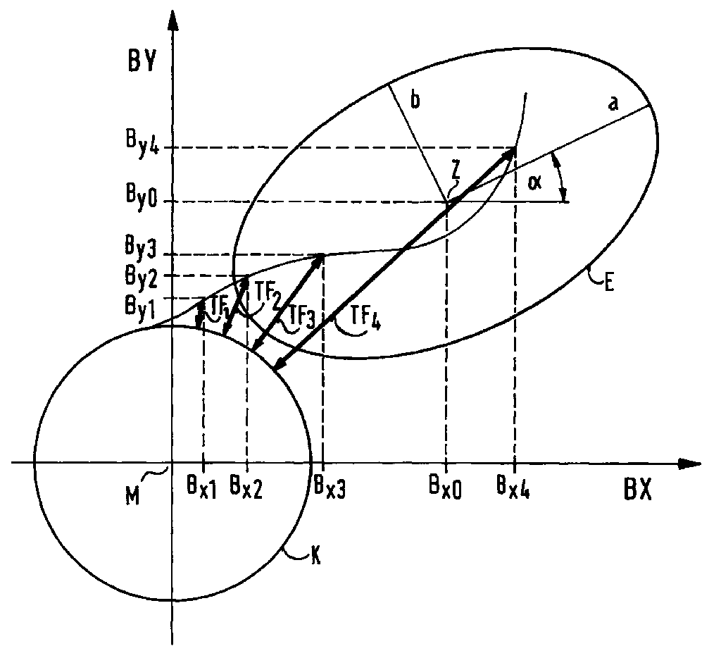
- the attached figure again illustrates the inventive concept.
- This figure shows a graphical illustration of measurement data which have been recorded with a magnetic field sensor.
- the pairs of values (B x ; B y ) are each entered in a memory which maps a two-dimensional coordinate network with the coordinate axes BX and BY and the origin M.
- the coordinate network represents the measuring plane and the coordinate axes BX and BY represent the measuring directions of the magnetic field sensor.
- the components B x and B y are used in the present memory organization like Cartesian coordinates.
- Measuring circuit " A complete Measuring circuit "arises when measurement data has been acquired in all directions of the measuring plane due to the movement of the compass device in the earth's magnetic field.
- the center Z of the ellipse the coordinates of which are designated B x0 and B y0 in the figure, can be obtained from the measurement data recorded with the magnetic field sensor, and determine the semiaxes a and b of the ellipse.
- the angle of rotation ⁇ by which the ellipse with its large semiaxis may be rotated against the abscissa of the coordinate network can be determined.
- the relevant pair of values (B x ; B y ) will therefore not be included in a subsequent direction determination or angle calculation, but can be deleted from the memory if permanent storage of the measurement data is not provided in the compass device. If the barrier value applies to the transformation error TF:
- the time behavior of the transformation error TF determined by the derivative dTF / dt, can also be used as a filter criterion.
- An appropriate determination for this limit value is:
- the proposed method thus shows two criteria with which it can be decided, individually or in combination, when a pair of values (B x ; B y ) is to be assessed as having a fault. It also reveals tried and tested barrier values for sensible filtering. After methods for eliminating static interference on measurement data from magnetic field sensors are already known, the proposed method offers a supplement to achieve the highest possible accuracy when determining directional information or angle information when using electronic compass devices.
- the accuracy of determining directional information or angle information can be improved by using the method according to the invention in an iterative process, which will now be explained below.
- the measured data acquired is distributed at least in part along the circumferential line E of an ellipse after a certain time.
- the parameters of the measurement data distribution are calculated, which are usually the parameters B x0 , B y0 , a, b and ⁇ of the ellipse E, with the help of which in connection with a transformation of the measurement data to calculate the desired directional information or angle information.
- the newly received measurement data can already be evaluated using the improved ellipse parameters. If it is provided that the compass device permanently stores the measurement data recorded before the recalculation of the ellipse parameters, the existing data stock can also be checked again using the improved ellipse parameters. The iterative process can be continued in that after a certain time after the last calculation of the ellipse parameters, if a significant number of measurement data have been recorded again, the ellipse parameters can again be recalculated on the basis of the filtered measurement data that is then available.
- This procedure is particularly advantageous if the ellipse parameters for Reaching the basic functionality of the compass device for the first time have been firmly entered, for example in the manufacture of Compass setup could have happened.
- the compass device takes the iterative process into account in its process Treatment of the measurement data of a magnetic field sensor very soon the real one Operating conditions that are given by the environment in which the Compass device is operated.
Landscapes
- Engineering & Computer Science (AREA)
- Radar, Positioning & Navigation (AREA)
- Remote Sensing (AREA)
- Physics & Mathematics (AREA)
- General Physics & Mathematics (AREA)
- Measuring Magnetic Variables (AREA)
- Geophysics And Detection Of Objects (AREA)
Abstract
Um den von zeitlich veränderlichen magnetischen Störfeldern ausgeübten Einfluß
auf die Meßdaten eines Magnetfeldsensors auszufiltern, wobei die Meßdaten vom
Magnetfeldsensor zu diskreten Zeitpunkten ti mit i = 1 bis n erfaßt werden und
jeweils aus einem Wertepaar von orthogonal zueinander stehenden Komponenten
des Erdmagnetfeldes bestehen, wird ein Verfahren vorgeschlagen, daß den
Transformationsfehler TF und gegebenenfalls dessen Zeitverhalten ermittelt und
bewertet, wobei der Transformationsfehler TF als der Abstand der Koordinaten
eines Wertepaares vom Einheitskreis K definiert ist, auf den das Wertepaar zur
Ermittlung einer Winkelinformation ausgehend von seiner Lage innerhalb einer
Meßdatenansammlung transformiert wird, wobei die Meßdatenansammlung
zumindest stückweise entlang der Ümfangslinie E einer Ellipse besteht und in
einer durch die Meßrichtungen des Magnetfeldsensors aufgespannten Meßebene
liegt.
Description
Die Erfindung betrifft ein Verfahren zur Filterung von Meßdaten eines Magnetfeldsensors gemäß dem Oberbegriff des ersten Anspruchs.The invention relates to a method for filtering measurement data of a Magnetic field sensor according to the preamble of the first claim.
Aufbau und Betriebsschaltungen von Magnetfeldsensoren sind bekannt, beispielsweise aus den Schriften DE 41 36 451 A1 und DE 195 38 757 C1. Magnetfeldsensoren werden beispielsweise in elektronischen Kompaßeinrichtungen eingesetzt, um durch eine Erfassung der räumlichen Komponenten des Erdmagnetfeldes zu einer Richtungsinformation bzw. Winkelinformation zu gelangen. Im praktischen Einsatz werden die Komponenten des Erdmagnetfeldes jedoch häufig durch zeitlich veränderliche magnetische Störfelder überlagert, die zu einer Verfälschung der Meßdaten führen.Structure and operating circuits of magnetic field sensors are known for example from the documents DE 41 36 451 A1 and DE 195 38 757 C1. Magnetic field sensors are used, for example, in electronic Compass devices used to measure the spatial Components of the earth's magnetic field for directional information or To get angle information. The components are put to practical use of the earth's magnetic field, however, often due to time-varying magnetic Interference fields are superimposed, which lead to falsification of the measurement data.
Es ist nun die Aufgabe der vorliegenden Erfindung, ein Verfahren aufzuzeigen, mit dem der auf die Meßdaten eines Magnetfeldsensors ausgeübte Einfluß von zeitlich veränderlichen magnetischen Störfeldern ausgefiltert wird. Auch geht es darum, Kriterien zu finden, wann Meßdaten als Störung zu bewerten sind. Die vorliegende Problemstellung ergibt sich insbesondere bei sehr einfach gestalteten, und damit preiswerten, autarken Kompaßeinrichtungen, bei denen eine Korrektur der erfaßten Meßdaten nicht durch eine vergleichende Auswertung anderer, nicht aus dem Erdmagnetfeld gewonnener Meßgrößen erfolgen kann. It is now the object of the present invention to demonstrate a method with which is the influence exerted on the measurement data of a magnetic field sensor time-varying magnetic interference fields is filtered out. It also works about finding criteria for when measurement data should be assessed as a fault. The The problem at hand arises particularly with very simple designed, and therefore inexpensive, self-sufficient compass devices in which a correction of the recorded measurement data not by means of a comparative evaluation other measurements not obtained from the earth's magnetic field can take place.
Die Aufgabe wird durch die Merkmale des ersten Anspruchs gelöst. Die abhängigen Ansprüche zeigen vorteilhafte Ausgestaltungen und Weiterbildungen der gefundenen Lösung.The object is achieved by the features of the first claim. The dependent claims show advantageous refinements and developments the solution found.
Die Lösung setzt die Verwendung eines Verfahrens zur Auswertung von Meßdaten eines Magnetfeldsensors voraus, bei dem als Meßdaten die Komponenten des Erdmagnetfeldes in einem zeitlichen Takt erfaßt und zur Gewinnung einer Winkelinformation auf einen Einheitskreis transformiert werden. Einzelheiten eines solchen Verfahrens sind beispielsweise in den Schriften DE 42 34 651 C1 und DE 44 23 845 C1 beschrieben. Durch Verfahren, bei denen die Meßdaten auf einen Einheitskreis transformiert werden, gelingt es bereits, den Einfluß von statischen Störfeldern zu eliminieren.The solution implies the use of a method for evaluating Measurement data of a magnetic field sensor ahead, in which the measurement data Components of the earth's magnetic field are recorded in a time cycle and for Obtaining an angle information can be transformed to a unit circle. Details of such a method can be found, for example, in DE 42 34 651 C1 and DE 44 23 845 C1. Through procedures in which the Measured data are transformed into a unit circle, the Eliminate the influence of static interference fields.
Vor der Transformation verteilen sich die erfaßten Meßdaten in ihrer grafischen
Abbildung in der Meßebene in aller Regel zumindest stückweise entlang der
Umfangslinie einer in der Meßebene liegenden Ellipse, die auch 
Für den Fall, daß ein Magnetfeldsensor parallel zur Erdoberfläche zwei
zueinander orthogonale Komponenten des Erdmagnetfeldes fortlaufend zu
diskreten Zeitpunkten ti mit i = 1 bis n als ein Wertepaar erfaßt, wobei die
Komponenten des Wertepaares nicht notwendigerweise exakt gleichzeitig erfaßt
werden müssen, aber zumindest bezüglich ihres Erfassungszeitpunktes
miteinander korrespondieren, ergibt sich der als Abstand vom Einheitskreis
definierte Transformationsfehler TF für dieses Wertepaar nach folgender Formel:
- Bx und By sind die Koordinaten des aktuell erfaßten Wertepaares,
- Bx0 und By0 bezeichnen die Mittelpunktskoordinaten des
- a und b bezeichnen die Halbachsen der Ellipse,
- α steht für den Drehwinkel der Ellipse in der Meßebene.
- B x and B y are the coordinates of the currently recorded pair of values,
- B x0 and B y0 denote the center coordinates of the
- a and b denote the semi-axes of the ellipse,
- α stands for the angle of rotation of the ellipse in the measuring plane.
Es wird vorgeschlagen, von diesem Transformationsfehler TF auch die erste
zeitliche Ableitung dTF/dt zu bilden, weil dadurch kurzzeitige Ausreißer bei den
kontinuierlich erfaßten Meßdaten zuverlässig ausgefiltert werden können. Wenn
sich der Transformationsfehler TF oder dessen Ableitung dTF/dt sprunghaft aus
einem festgelegten Toleranzbereich hinausbewegt, deutet dieses auf eine
Störung hin, die durch ein äußeres, zeitlich veränderliches magnetisches Störfeld
hervorgerufen wurde. Für den Toleranzbereich, innerhalb dem die Meßdaten Bx
und By zu akzeptieren und demnach nicht auszufiltern sind, haben sich folgende
Werte als zweckmäßig erwiesen:
Diese Filterparameter |TF| und |dTF /dt|, die als Schrankenwerte definiert sind, sollten nicht zu scharf gewählt werden, weil sonst die Gefahr besteht, daß zu viele Meßdaten ausgefiltert werden oder das Meßsystem insgesamt zu langsam wird, weil in einem bestimmten Zeitraum, der zum Sammeln von Meßdaten für eine Berechnung der Ellipsenparameter benötigt wird, welche ihrerseits die Voraussetzung für eine Ermittlung der Winkelinformation bilden, zu wenige Meßdaten zur Verfügung stehen. Denn der für die Ermittlung der Ellipsenparameter und der Winkelinformation zugrundeliegende Zeitraum kann beispielsweise durch die Anzahl n der zu erfassenden Wertepaare festgelegt sein. These filter parameters | TF | and | dTF / dt |, which are defined as limit values, should not be chosen too sharply, otherwise there is a risk that too many Measurement data are filtered out or the measuring system as a whole becomes too slow, because in a certain period of time, which is used to collect measurement data for a Calculation of the ellipse parameters is required, which in turn the Too little prerequisite for determining the angle information Measurement data are available. Because that for the determination of the Ellipse parameters and the period of time on which the angle information is based be determined, for example, by the number n of the pairs of values to be recorded.
Andererseits führt eine angemessene Bewertung des Transformationsfehlers TF und seines Zeitverhaltens dazu, daß der Einfluß zeitlich veränderlicher Störfelder wirksam zurückgedrängt wird, wodurch die Genauigkeit der durch die Kompaßeinrichtung zu ermittelnden Winkelinformation verbessert wird.On the other hand, an adequate evaluation of the transformation error TF leads and its time behavior to the influence of time-varying interference fields is effectively pushed back, thereby reducing the accuracy of the Compass device to be determined angle information is improved.
Die beigefügte Figur verdeutlicht nochmals den Erfindungsgedanken. Diese Figur zeigt eine grafische Abbildung von Meßdaten, die mit einem Magnetfeldsensor erfaßt worden sind. Die Meßdaten werden in einem zeitlichen Takt erfaßt, und zwar derart, daß für diskrete aufeinanderfolgende Zeitpunkte ti mit i = 1 bis n jeweils ein Wertepaar mit den Komponenten Bx und By vorliegt, wobei diese Komponenten für Meßwerte stehen, die der Stärke des Erdmagnetfeldes in zwei orthogonal zueinander stehenden Raumrichtungen proportional sind. Die Wertepaare (Bx; By) werden jeweils in einen Speicher eingetragen, der ein zweidimensionales Koordinatennetz mit den Koordinatenachsen BX und BY und dem Ursprung M abbildet. Dabei repräsentiert das Koordinatennetz die Meßebene und die Koordinatenachsen BX und BY stehen für die Meßrichtungen des Magnetfeldsensors. Die Komponenten Bx und By werden bei der vorliegenden Speicherorganisation wie kartesische Koordinaten verwendet.The attached figure again illustrates the inventive concept. This figure shows a graphical illustration of measurement data which have been recorded with a magnetic field sensor. The measurement data are recorded in a time cycle, in such a way that for discrete successive times t i with i = 1 to n there is a pair of values with the components B x and B y , these components representing measurement values that correspond to the strength of the Earth's magnetic field are proportional in two orthogonal spatial directions. The pairs of values (B x ; B y ) are each entered in a memory which maps a two-dimensional coordinate network with the coordinate axes BX and BY and the origin M. The coordinate network represents the measuring plane and the coordinate axes BX and BY represent the measuring directions of the magnetic field sensor. The components B x and B y are used in the present memory organization like Cartesian coordinates.
Nach einer gewissen Zeit, nachdem eine gewisse Menge von Meßdaten erfaßt
worden sind, sieht man, daß sich bei einer üblichen Verwendung einer mit einem
Magnetfeldsensor ausgerüsteten Kompaßeinrichtung die Meßdaten zumindest
stückweise entlang der Umfangslinie E einer Ellipse verteilen. Die grafische
Abbildung der Meßdatenverteilung wird
Mit einem bekannten Verfahren, wie beispielsweise mit dem in der eingangs
genannten Schrift DE 44 23 845 C1 beschriebenen, läßt sich aus den mit dem
Magnetfeldsensor erfaßten Meßdaten das Zentrum Z der Ellipse, dessen
Koordinaten in der Figur mit Bx0 und By0 bezeichnet sind, und die Halbachsen a
und b der Ellipse ermitteln. Auch der Drehwinkel α, um den die Ellipse mit ihrer
großen Halbachse gegen die Abszisse des Koordinatennetzes verdreht sein mag,
kann bestimmt werden. Mit diesen Parametern sind die momentane, sich aus der
vorliegenden Meßdatensammlung ergebende Lage und Form des
Nachdem die Ellipsenparameter Bx0, By0, a, b und α bestimmt worden sind, kann
zu den als Wertepaar (Bx; By) einlaufenden Meßdaten nach folgender Formel ein
Winkel ψ berechnet werden:
Zur Beseitigung von Einflüssen, die auf ein äußeres, zeitlich veränderliches magnetisches Störfeld zurückgehen, wird nun erfindungsgemäß von jedem erfaßten Wertepaar (Bx; By) sein Abstand zum Einheitskreis K ermittelt. Dieser Abstand repräsentiert einen Transformationsfehler TF. Er steht stets lotrecht auf der Umfangslinie des Einheitskreises K. In der Figur ist für vier Meßzeitpunkte t1, t2, t3 und t4 der zu dem jeweiligen Wertepaar (Bx; By) gehörende Transformationsfehler TF eingezeichnet. Wenn der absolute Betrag des Transformationsfehlers TF ein festgesetztes Maß überschreitet, soll gemäß der Erfindung das betreffende Wertepaar (Bx; By) ausgefiltert werden. Das betreffende Wertepaar (Bx; By) wird somit in eine anschließende Richtungsbestimmung oder Winkelberechnung nicht eingehen, sondern kann, falls in der Kompaßeinrichtung eine dauerhafte Speicherung der Meßdaten nicht vorgesehen ist, aus dem Speicher gelöscht werden. Wenn für den Transformationsfehler TF der Schrankenwert gilt: |TF| < 1, so würde in der dargestellten Figur das vierte Wertepaar (Bx4; By4) verworfen, wohingegen die ersten drei Wertepaare (Bx1; By1), (Bx2; By2) und (Bx3; By3) noch weiter berücksichtigt werden.In order to eliminate influences due to an external, time-varying magnetic interference field, its distance from the unit circle K is determined according to the invention for each pair of values (B x ; B y ) detected. This distance represents a transformation error TF. It is always perpendicular to the circumference of the unit circle K. The transformation error TF belonging to the respective pair of values (B x ; B y ) is drawn in for four measuring times t 1 , t 2 , t 3 and t 4 . If the absolute magnitude of the transformation error TF exceeds a fixed dimension, the relevant pair of values (B x ; B y ) should be filtered out according to the invention. The relevant pair of values (B x ; B y ) will therefore not be included in a subsequent direction determination or angle calculation, but can be deleted from the memory if permanent storage of the measurement data is not provided in the compass device. If the barrier value applies to the transformation error TF: | TF | <1, the fourth pair of values (B x4 ; B y4 ) would be rejected in the figure shown, whereas the first three pairs of values (B x1 ; B y1 ), (B x2 ; B y2 ) and (B x3 ; B y3 ) would still be discarded be considered further.
In vielen Anwendungen ist es sinnvoll, durch Bildung der ersten zeitlichen
Ableitung des Transformationsfehlers TF auch festzustellen, wie schnell sich der
ermittelte Transformationsfehler TF verändert. Auch das Zeitverhalten des
Transformationsfehlers TF, bestimmt durch die Ableitung dTF/dt, kann gut als
Filterkriterium benutzt werden. Eine zweckmäßige Festsetzung für diesen
Schrankenwert ist:
Das vorgeschlagene Verfahren zeigt somit zwei Kriterien auf, mit denen einzeln oder in Kombination entschieden werden kann, wann ein Wertepaar (Bx; By) als störbehaftet zu beurteilen ist. Auch offenbart es praxiserprobte Schrankenwerte für eine sinnvolle Filterung. Nachdem Verfahren zur Eliminierung statischer Störeinflüsse auf Meßdaten von Magnetfeldsensoren bereits bekannt sind, bietet das vorgeschlagene Verfahren eine Ergänzung, um bei einer üblichen Verwendung von elektronischen Kompaßeinrichtungen eine möglichst hohe Genauigkeit bei der Bestimmung von Richtungsangaben oder Winkelinformationen zu erreichen.The proposed method thus shows two criteria with which it can be decided, individually or in combination, when a pair of values (B x ; B y ) is to be assessed as having a fault. It also reveals tried and tested barrier values for sensible filtering. After methods for eliminating static interference on measurement data from magnetic field sensors are already known, the proposed method offers a supplement to achieve the highest possible accuracy when determining directional information or angle information when using electronic compass devices.
Des weiteren kann die Genauigkeit der Bestimmung von Richtungsangaben oder Winkelinformationen dadurch verbessert werden, daß das erfindungsgemäße Verfahren in einem iterativen Prozeß verwendet wird, der nun nachfolgend erläutert werden soll. Es wurde bereits erwähnt, daß sich bei einer üblichen Verwendung einer mit einem Magnetfeldsensor ausgerüsteten Kompaßeinrichtung die erfaßten Meßdaten nach einer gewissen Zeit zumindest stückweise entlang der Umfangslinie E einer Ellipse verteilen. Aus dieser Menge von ungefilterten Meßdaten, den sogenannten Rohdaten, werden die Parameter der Meßdatenverteilung berechnet, was im Regelfall die Parameter Bx0, By0, a, b und α der Ellipse E sind, um mit deren Hilfe in Verbindung mit einer Transformation der Meßdaten die gewünschten Richtungsangaben oder Winkelinformationen zu berechnen.Furthermore, the accuracy of determining directional information or angle information can be improved by using the method according to the invention in an iterative process, which will now be explained below. It has already been mentioned that when a compass device equipped with a magnetic field sensor is used normally, the measured data acquired is distributed at least in part along the circumferential line E of an ellipse after a certain time. From this set of unfiltered measurement data, the so-called raw data, the parameters of the measurement data distribution are calculated, which are usually the parameters B x0 , B y0 , a, b and α of the ellipse E, with the help of which in connection with a transformation of the measurement data to calculate the desired directional information or angle information.
In gewissen Applikationen von Kompaßeinrichtungen ist es sinnvoll, das vorgeschlagene Verfahren zur Filterung von Meßdaten eines Magnetfeldsensors nicht nur statisch, d.h. mit einem feststehenden Satz von Ellipsenparametern zu betreiben, sondern es in einen dynamischen, iterativen Prozeß einzubeziehen, indem die Ellipsenparameter Bx0, By0, a, b und α aus der Menge der gefilterten Meßdaten erneut berechnet werden. Dadurch, daß in der erneuten Berechnung der Ellipsenparameter störbehaftete Meßdaten, die in der Menge der Rohdaten vorgelegen haben mögen, nicht mehr einbezogen werden, wird die Genauigkeit der Werte für die Ellipsenparameter Bx0, By0, a, b und α verbessert, was sich wiederum günstig auf die Genauigkeit der anschließenden Bestimmung der Richtungsangaben oder Winkelinformationen auswirkt.In certain applications of compass devices, it makes sense not only to operate the proposed method for filtering measurement data from a magnetic field sensor statically, ie with a fixed set of ellipse parameters, but also to include it in a dynamic, iterative process by using the ellipse parameters B x0 , B y0 , a, b and α are recalculated from the amount of filtered measurement data. The fact that the recalculation of the ellipse parameters no longer includes measurement data with interference, which may have been present in the amount of raw data, improves the accuracy of the values for the ellipse parameters B x0 , B y0 , a, b and α, which improves in turn has a favorable effect on the accuracy of the subsequent determination of the directional information or angle information.
Da vom Magnetfeldsensor auch nach der ersten Berechnung der Ellipsenparameter Bx0, By0, a, b und α weiterhin fortlaufend Meßdaten erfaßt werden, können die neu eingehenden Meßdaten bereits anhand der verbesserten Ellipsenparameter bewertet werden. Sofern vorgesehen ist, daß die Kompaßeinrichtung die vor der Neuberechnung der Ellipsenparameter erfaßten Meßdaten dauerhaft speichert, kann auch der vorhandene Datenbestand nochmals anhand der verbesserten Ellipsenparameter überprüft werden. Der iterative Prozeß kann dadurch fortgesetzt werden, daß nach einer gewissen Zeit nach der letzten Berechnung der Ellipsenparameter, wenn wieder eine bedeutsame Anzahl von Meßdaten erfaßt worden sind, die Ellipsenparameter wiederum anhand der dann vorliegenden, gefilterten Meßdaten neu berechnet werden können.Since the magnetic field sensor continues to acquire measurement data even after the first calculation of the ellipse parameters B x0 , B y0 , a, b and α, the newly received measurement data can already be evaluated using the improved ellipse parameters. If it is provided that the compass device permanently stores the measurement data recorded before the recalculation of the ellipse parameters, the existing data stock can also be checked again using the improved ellipse parameters. The iterative process can be continued in that after a certain time after the last calculation of the ellipse parameters, if a significant number of measurement data have been recorded again, the ellipse parameters can again be recalculated on the basis of the filtered measurement data that is then available.
Auf diese Weise kann ein iterativer Prozeß in Gang gebracht werden, der beispielsweise solange fortgesetzt wird, bis sich die Werte von zwei aufeinanderfolgenden Berechnungen der Ellipsenparameter nur noch innerhalb festgelegter Toleranzen voneinander unterscheiden. Man erreicht dadurch, daß sich die Ellipsenparameter Bx0, By0, a, b und α, deren Werte sich entscheidend auf die Bestimmung der Richtungsangaben oder Winkelinformationen auswirken, schrittweise optimalen Werten anpassen.In this way, an iterative process can be started which continues, for example, until the values of two successive calculations of the ellipse parameters differ from one another only within defined tolerances. The result is that the ellipse parameters B x0 , B y0 , a, b and α, the values of which have a decisive effect on the determination of the directional information or angle information, are gradually adapted to optimal values.
Dieses Vorgehen ist dann besonders vorteilhaft, wenn die Ellipsenparameter zum Erreichen der grundsätzlichen Funktionsfähigkeit der Kompaßeinrichtung erstmals fest eingegeben worden sind, was beispielsweise bei der Herstellung der Kompaßeinrichtung geschehen sein könnte. Durch den zuvor beschriebenen iterativen Prozeß berücksichtigt die Kompaßeinrichtung in ihrem Verfahren zur Behandlung der Meßdaten eines Magnetfeldsensors sehr bald die realen Betriebsbedingungen, die durch die Umwelt gegeben sind, in der die Kompaßeinrichtung betrieben wird.This procedure is particularly advantageous if the ellipse parameters for Reaching the basic functionality of the compass device for the first time have been firmly entered, for example in the manufacture of Compass setup could have happened. By the previously described The compass device takes the iterative process into account in its process Treatment of the measurement data of a magnetic field sensor very soon the real one Operating conditions that are given by the environment in which the Compass device is operated.
Claims (7)

Applications Claiming Priority (2)
| Application Number | Priority Date | Filing Date | Title |
|---|---|---|---|
| DE19743471A DE19743471A1 (en) | 1997-10-01 | 1997-10-01 | Method for filtering measurement data from a magnetic field sensor |
| DE19743471 | 1997-10-01 |
Publications (3)
| Publication Number | Publication Date |
|---|---|
| EP0907067A2 true EP0907067A2 (en) | 1999-04-07 |
| EP0907067A3 EP0907067A3 (en) | 2000-07-05 |
| EP0907067B1 EP0907067B1 (en) | 2006-11-02 |
Family
ID=7844336
Family Applications (1)
| Application Number | Title | Priority Date | Filing Date |
|---|---|---|---|
| EP98117708A Expired - Lifetime EP0907067B1 (en) | 1997-10-01 | 1998-09-18 | Method for filtering the measured data of a magnetic field sensor |
Country Status (3)
| Country | Link |
|---|---|
| EP (1) | EP0907067B1 (en) |
| AT (1) | ATE344437T1 (en) |
| DE (2) | DE19743471A1 (en) |
Cited By (1)
| Publication number | Priority date | Publication date | Assignee | Title |
|---|---|---|---|---|
| CN113640726A (en) * | 2021-10-19 | 2021-11-12 | 青岛杰瑞自动化有限公司 | Multi-azimuth ellipse fitting calibration method and system for double-shaft magnetometer |
Family Cites Families (2)
| Publication number | Priority date | Publication date | Assignee | Title |
|---|---|---|---|---|
| ES2079204T3 (en) * | 1991-09-17 | 1996-01-01 | Siemens Ag | PROCEDURE FOR COMPENSATION OF A MAGNETIC FIELD OF INTERFERENCE IN A VEHICLE. |
| DE4423845C1 (en) * | 1994-07-07 | 1996-02-08 | Mannesmann Kienzle Gmbh | Method for determining the yaw angle of a vehicle |
-
1997
- 1997-10-01 DE DE19743471A patent/DE19743471A1/en not_active Withdrawn
-
1998
- 1998-09-18 DE DE59813782T patent/DE59813782D1/en not_active Expired - Fee Related
- 1998-09-18 AT AT98117708T patent/ATE344437T1/en not_active IP Right Cessation
- 1998-09-18 EP EP98117708A patent/EP0907067B1/en not_active Expired - Lifetime
Cited By (2)
| Publication number | Priority date | Publication date | Assignee | Title |
|---|---|---|---|---|
| CN113640726A (en) * | 2021-10-19 | 2021-11-12 | 青岛杰瑞自动化有限公司 | Multi-azimuth ellipse fitting calibration method and system for double-shaft magnetometer |
| CN113640726B (en) * | 2021-10-19 | 2021-12-21 | 青岛杰瑞自动化有限公司 | Multi-azimuth ellipse fitting calibration method and system for double-shaft magnetometer |
Also Published As
| Publication number | Publication date |
|---|---|
| EP0907067A3 (en) | 2000-07-05 |
| ATE344437T1 (en) | 2006-11-15 |
| DE59813782D1 (en) | 2006-12-14 |
| EP0907067B1 (en) | 2006-11-02 |
| DE19743471A1 (en) | 1999-04-08 |
Similar Documents
| Publication | Publication Date | Title |
|---|---|---|
| DE102016104285C5 (en) | Magnetic sensor | |
| DE19839450B4 (en) | Magnetoresistive sensor chip with at least two measuring elements designed as a half or full bridge | |
| WO2013139520A1 (en) | Magnetic field sensor, actuating device and method for determining a relative position | |
| DE102008020153A1 (en) | Angle detection device | |
| DE102007008870A1 (en) | Arrangement and method for the absolute determination of the linear position or the angular position expressed by an angle | |
| DE102016104208C5 (en) | Magnetic sensor | |
| DE102018113821A1 (en) | Angle sensor bridges including star-connected magnetoresistive elements | |
| EP0877488A1 (en) | Method for detecting the angle of rotation of a rotatable shaft, in particular of a rotatable switch, and device for carrying out the method | |
| EP2584304A1 (en) | Method for determining a distance and an integrated magnetic field measuring apparatus | |
| DE102017112623B4 (en) | State determination apparatus and method, physical quantity information generation apparatus, and angle sensor | |
| WO2011160796A2 (en) | Device for generating a sensor signal and method for determining the position of a sensor | |
| DE102020115050A1 (en) | MAGNETIC SENSOR AND MAGNETIC SENSOR SYSTEM | |
| DE4003563C2 (en) | Method for determining the direction of travel of a vehicle with a geomagnetic sensor | |
| DE102018127119A1 (en) | Magnetic sensor device | |
| EP1178326A1 (en) | Method and system to determine the orientation of a magnetic field with GMR sensors | |
| DE102016000257B4 (en) | MAGNETIC SENSOR SYSTEM | |
| DE102019122188B4 (en) | ANGLE SENSOR SYSTEM | |
| EP2121417A1 (en) | Method and device for determining a steering angle offset | |
| DE69121216T2 (en) | Device for determining the direction | |
| WO2004003478A2 (en) | Magnetoresistive sensor | |
| DE102004029815A1 (en) | Method and arrangement for correcting an angle and / or distance measuring sensor system | |
| DE4438715C1 (en) | Magnetic field sensor chip for linear or angular incremental measuring device | |
| DE4000345A1 (en) | Measuring orientation of moving object, esp. vehicle - using geomagnetic directional sensor to measure horizontal components of earths magnetic field, and compsn. for magnetisation changes | |
| EP1043569B1 (en) | Method for offset compensation of two orthogonal sensor signals | |
| DE102019133222A1 (en) | Magnetic sensor device |
Legal Events
| Date | Code | Title | Description |
|---|---|---|---|
| PUAI | Public reference made under article 153(3) epc to a published international application that has entered the european phase |
Free format text: ORIGINAL CODE: 0009012 |
|
| AK | Designated contracting states |
Kind code of ref document: A2 Designated state(s): AT CH DE FR GB LI NL |
|
| AX | Request for extension of the european patent |
Free format text: AL;LT;LV;MK;RO;SI |
|
| PUAL | Search report despatched |
Free format text: ORIGINAL CODE: 0009013 |
|
| AK | Designated contracting states |
Kind code of ref document: A3 Designated state(s): AT BE CH CY DE DK ES FI FR GB GR IE IT LI LU MC NL PT SE |
|
| AX | Request for extension of the european patent |
Free format text: AL;LT;LV;MK;RO;SI |
|
| 17P | Request for examination filed |
Effective date: 20000906 |
|
| AKX | Designation fees paid |
Free format text: AT CH DE FR GB LI NL |
|
| RAP1 | Party data changed (applicant data changed or rights of an application transferred) |
Owner name: SIEMENS AKTIENGESELLSCHAFT |
|
| 17Q | First examination report despatched |
Effective date: 20041029 |
|
| GRAP | Despatch of communication of intention to grant a patent |
Free format text: ORIGINAL CODE: EPIDOSNIGR1 |
|
| GRAS | Grant fee paid |
Free format text: ORIGINAL CODE: EPIDOSNIGR3 |
|
| GRAA | (expected) grant |
Free format text: ORIGINAL CODE: 0009210 |
|
| AK | Designated contracting states |
Kind code of ref document: B1 Designated state(s): AT CH DE FR GB LI NL |
|
| PG25 | Lapsed in a contracting state [announced via postgrant information from national office to epo] |
Ref country code: NL Free format text: LAPSE BECAUSE OF FAILURE TO SUBMIT A TRANSLATION OF THE DESCRIPTION OR TO PAY THE FEE WITHIN THE PRESCRIBED TIME-LIMIT Effective date: 20061102 |
|
| REG | Reference to a national code |
Ref country code: GB Ref legal event code: FG4D Free format text: NOT ENGLISH |
|
| REG | Reference to a national code |
Ref country code: CH Ref legal event code: EP |
|
| REF | Corresponds to: |
Ref document number: 59813782 Country of ref document: DE Date of ref document: 20061214 Kind code of ref document: P |
|
| REG | Reference to a national code |
Ref country code: CH Ref legal event code: NV Representative=s name: SIEMENS SCHWEIZ AG |
|
| GBT | Gb: translation of ep patent filed (gb section 77(6)(a)/1977) |
Effective date: 20070208 |
|
| NLV1 | Nl: lapsed or annulled due to failure to fulfill the requirements of art. 29p and 29m of the patents act | ||
| ET | Fr: translation filed | ||
| PLBE | No opposition filed within time limit |
Free format text: ORIGINAL CODE: 0009261 |
|
| STAA | Information on the status of an ep patent application or granted ep patent |
Free format text: STATUS: NO OPPOSITION FILED WITHIN TIME LIMIT |
|
| 26N | No opposition filed |
Effective date: 20070803 |
|
| PGFP | Annual fee paid to national office [announced via postgrant information from national office to epo] |
Ref country code: CH Payment date: 20080915 Year of fee payment: 11 |
|
| PG25 | Lapsed in a contracting state [announced via postgrant information from national office to epo] |
Ref country code: AT Free format text: LAPSE BECAUSE OF NON-PAYMENT OF DUE FEES Effective date: 20070918 |
|
| PGFP | Annual fee paid to national office [announced via postgrant information from national office to epo] |
Ref country code: FR Payment date: 20080912 Year of fee payment: 11 |
|
| PGFP | Annual fee paid to national office [announced via postgrant information from national office to epo] |
Ref country code: GB Payment date: 20080918 Year of fee payment: 11 |
|
| PGFP | Annual fee paid to national office [announced via postgrant information from national office to epo] |
Ref country code: DE Payment date: 20080919 Year of fee payment: 11 |
|
| REG | Reference to a national code |
Ref country code: CH Ref legal event code: PCAR Free format text: SIEMENS SCHWEIZ AG;INTELLECTUAL PROPERTY FREILAGERSTRASSE 40;8047 ZUERICH (CH) |
|
| REG | Reference to a national code |
Ref country code: CH Ref legal event code: PL |
|
| GBPC | Gb: european patent ceased through non-payment of renewal fee |
Effective date: 20090918 |
|
| REG | Reference to a national code |
Ref country code: FR Ref legal event code: ST Effective date: 20100531 |
|
| PG25 | Lapsed in a contracting state [announced via postgrant information from national office to epo] |
Ref country code: FR Free format text: LAPSE BECAUSE OF NON-PAYMENT OF DUE FEES Effective date: 20090930 Ref country code: DE Free format text: LAPSE BECAUSE OF NON-PAYMENT OF DUE FEES Effective date: 20100401 |
|
| PG25 | Lapsed in a contracting state [announced via postgrant information from national office to epo] |
Ref country code: LI Free format text: LAPSE BECAUSE OF NON-PAYMENT OF DUE FEES Effective date: 20090930 Ref country code: CH Free format text: LAPSE BECAUSE OF NON-PAYMENT OF DUE FEES Effective date: 20090930 |
|
| PG25 | Lapsed in a contracting state [announced via postgrant information from national office to epo] |
Ref country code: GB Free format text: LAPSE BECAUSE OF NON-PAYMENT OF DUE FEES Effective date: 20090918 |