EP0907060A2 - Opposite flows equipment, particularly for the fast heat reduction in the cooked and raw food preservation cycles even in the freezing - Google Patents
Opposite flows equipment, particularly for the fast heat reduction in the cooked and raw food preservation cycles even in the freezing Download PDFInfo
- Publication number
- EP0907060A2 EP0907060A2 EP98118286A EP98118286A EP0907060A2 EP 0907060 A2 EP0907060 A2 EP 0907060A2 EP 98118286 A EP98118286 A EP 98118286A EP 98118286 A EP98118286 A EP 98118286A EP 0907060 A2 EP0907060 A2 EP 0907060A2
- Authority
- EP
- European Patent Office
- Prior art keywords
- opposite
- equipment
- fast heat
- previous
- heat reduction
- Prior art date
- Legal status (The legal status is an assumption and is not a legal conclusion. Google has not performed a legal analysis and makes no representation as to the accuracy of the status listed.)
- Granted
Links
Images

Classifications
-
- A—HUMAN NECESSITIES
- A23—FOODS OR FOODSTUFFS; TREATMENT THEREOF, NOT COVERED BY OTHER CLASSES
- A23L—FOODS, FOODSTUFFS, OR NON-ALCOHOLIC BEVERAGES, NOT COVERED BY SUBCLASSES A21D OR A23B-A23J; THEIR PREPARATION OR TREATMENT, e.g. COOKING, MODIFICATION OF NUTRITIVE QUALITIES, PHYSICAL TREATMENT; PRESERVATION OF FOODS OR FOODSTUFFS, IN GENERAL
- A23L3/00—Preservation of foods or foodstuffs, in general, e.g. pasteurising, sterilising, specially adapted for foods or foodstuffs
- A23L3/34—Preservation of foods or foodstuffs, in general, e.g. pasteurising, sterilising, specially adapted for foods or foodstuffs by treatment with chemicals
- A23L3/3409—Preservation of foods or foodstuffs, in general, e.g. pasteurising, sterilising, specially adapted for foods or foodstuffs by treatment with chemicals in the form of gases, e.g. fumigation; Compositions or apparatus therefor
- A23L3/3418—Preservation of foods or foodstuffs, in general, e.g. pasteurising, sterilising, specially adapted for foods or foodstuffs by treatment with chemicals in the form of gases, e.g. fumigation; Compositions or apparatus therefor in a controlled atmosphere, e.g. partial vacuum, comprising only CO2, N2, O2 or H2O
-
- A—HUMAN NECESSITIES
- A23—FOODS OR FOODSTUFFS; TREATMENT THEREOF, NOT COVERED BY OTHER CLASSES
- A23L—FOODS, FOODSTUFFS, OR NON-ALCOHOLIC BEVERAGES, NOT COVERED BY SUBCLASSES A21D OR A23B-A23J; THEIR PREPARATION OR TREATMENT, e.g. COOKING, MODIFICATION OF NUTRITIVE QUALITIES, PHYSICAL TREATMENT; PRESERVATION OF FOODS OR FOODSTUFFS, IN GENERAL
- A23L3/00—Preservation of foods or foodstuffs, in general, e.g. pasteurising, sterilising, specially adapted for foods or foodstuffs
- A23L3/36—Freezing; Subsequent thawing; Cooling
-
- F—MECHANICAL ENGINEERING; LIGHTING; HEATING; WEAPONS; BLASTING
- F25—REFRIGERATION OR COOLING; COMBINED HEATING AND REFRIGERATION SYSTEMS; HEAT PUMP SYSTEMS; MANUFACTURE OR STORAGE OF ICE; LIQUEFACTION SOLIDIFICATION OF GASES
- F25D—REFRIGERATORS; COLD ROOMS; ICE-BOXES; COOLING OR FREEZING APPARATUS NOT OTHERWISE PROVIDED FOR
- F25D13/00—Stationary devices, e.g. cold-rooms
- F25D13/06—Stationary devices, e.g. cold-rooms with conveyors carrying articles to be cooled through the cooling space
- F25D13/067—Stationary devices, e.g. cold-rooms with conveyors carrying articles to be cooled through the cooling space with circulation of gaseous cooling fluid
-
- F—MECHANICAL ENGINEERING; LIGHTING; HEATING; WEAPONS; BLASTING
- F25—REFRIGERATION OR COOLING; COMBINED HEATING AND REFRIGERATION SYSTEMS; HEAT PUMP SYSTEMS; MANUFACTURE OR STORAGE OF ICE; LIQUEFACTION SOLIDIFICATION OF GASES
- F25D—REFRIGERATORS; COLD ROOMS; ICE-BOXES; COOLING OR FREEZING APPARATUS NOT OTHERWISE PROVIDED FOR
- F25D17/00—Arrangements for circulating cooling fluids; Arrangements for circulating gas, e.g. air, within refrigerated spaces
- F25D17/04—Arrangements for circulating cooling fluids; Arrangements for circulating gas, e.g. air, within refrigerated spaces for circulating air, e.g. by convection
- F25D17/06—Arrangements for circulating cooling fluids; Arrangements for circulating gas, e.g. air, within refrigerated spaces for circulating air, e.g. by convection by forced circulation
- F25D17/067—Evaporator fan units
-
- F—MECHANICAL ENGINEERING; LIGHTING; HEATING; WEAPONS; BLASTING
- F25—REFRIGERATION OR COOLING; COMBINED HEATING AND REFRIGERATION SYSTEMS; HEAT PUMP SYSTEMS; MANUFACTURE OR STORAGE OF ICE; LIQUEFACTION SOLIDIFICATION OF GASES
- F25D—REFRIGERATORS; COLD ROOMS; ICE-BOXES; COOLING OR FREEZING APPARATUS NOT OTHERWISE PROVIDED FOR
- F25D2400/00—General features of, or devices for refrigerators, cold rooms, ice-boxes, or for cooling or freezing apparatus not covered by any other subclass
- F25D2400/28—Quick cooling
Definitions
- the present invention has for object an opposite flows equipment particularly for a fast heat reduction, in the cooked and raw food preservation cycles even in freezing.
- the invention finds particular even if not exclusive application in the sector of large plants for the food production-preservation and in public restaurant services.
- the temperature fast reducers are known, also with the name of thermal reducers. They were created rather recently on the basis of a common experience of the operators working in the field of the public restaurant services and in general in food production, who, having to resort always more frequently to pre-cooked or frozen food, found that once the cooking was effected, the food, when not immediately eaten undergoes a fast degradation, on one side altering the food's organoleptic characteristic, but mainly being a good medium for the proliferation of bacteria.
- said equipment known as indirect cooling device, is subdivided into two large groups, the single-lateral flow group and the single-frontal flow ones.
- the first ones are those widely used and are essentially made up of a body with an internally insulated double wall, with a steel base provided with small feet.
- the internal part comprises a laterally placed reduction chamber with the relative access, also in steel, provided with walls for the conveyance of air.
- the evaporator group is provided, with its relative compressor, placed inside the equipment, protected in an accessible opening.
- a forced ventilation system is provided, with electric impellers which have the purpose of removing the heat from the food inserted, for conveying the hot air towards the evaporator, and thus crossing the same in a single direction, re-inserting a cold air flow in the reduction chamber, conveying it to reach the walls.
- the drawbacks found in this solution consist relate mainly to time, not short enough, to reach the safety threshold, of a low yield/productive capacity as well as of an irregular temperature decrease occurring on the surfaces of the food thus treated.
- said equipment for obtaining satisfactory results must use a great power, with the consequent plant oversizing and rather high electric power consumptions.
- the position and the structure of the evaporator group has substantially remained unchanged in time.
- it is placed at a certain distance from the chamber back, this in order that the air, frontally sucked by the electric impeller, surrounding in one direction the finned pipes may expand in the rear hollow space and continue its course, contacting the lateral walls to later be inserted again in the reduction chamber.
- a surface made up of a finned piping is provided, which does not concern at all the whole chamber length but is limited to a portion of same. Thus, some lateral openings or channels are obtained, through which the air re-circulation flow is made pass.
- evaporators also involves high management costs, relative to their high power consumption. Furthermore, they impose a certain dimensioning with important limits in respect to the heat elimination capacity and speed, not suitably exploiting those spaces, substantially unused, which may be technically exploited for a better yield. With similar structures, thus, further increasing the evaporator yield is not possible unless dimensionally modifying at least the inside of the chamber and as a consequence, inserting a larger sized evaporator. Substantially, regarding the production and the economical aspect, the whole is negatively reflected on quality, but also on the manufacturing process, forcing the firm to a complex management of the productive unit, with a lack of flexibility in the offer system.
- an opposite double flow equipment particularly for a fast heat reduction, in the cooked or frozen food preservation of the type
- a body with relative base suitably insulated, said body being able to enclose at least three intercommunicating areas, a first centrally located one, making up a reduction chamber, inside which the baking-pans with the food being subjected to treatment will be inserted, and two diametrically opposed ones communicating with said first one, each being made up of at least one evaporator fed by at least a compressor group and corresponding electric impellers, using:
- the advantages also consist of a further reduction in the treatment times of the cooked or raw food, reaching a matchless hourly production. Furthermore, other benefits, found in the functions are attributable to the obtainment of a temperature reduction decidedly more even regarding the food thus inserted, with clear better guarantees for the elimination of the bacterial mass.
- an improved equipment (A) particularly aiming at the ultra fast reduction of the cooked and raw food temperature, is essentially made up of a body (1), preferably in stainless steel, internally insulated and provided on the underlying part with a base, preferably also in stainless steel.
- Said body (1) perimetrically defines the equipment (A), consisting of a shape, for example parallelepiped like and not excessively developed in width, essentially subdivided in three areas, a first central one (b) and two diametrically opposed ones (c, c'), that is respectively obtained to the side of said first one (b).
- the central area (b) makes up the reduction chamber and is provided with a small door (2), hinged on the side, for the frontal access inside of said chamber (b), allowing the insertion of the food-holding baking pans (3) and eventually of the relative tray.
- a second opening (2') may be provided, obtained on the back of the equipment. Practically, it allows the making of a modular line, consisting of a plurality of reducers (A, A', A''...) placed one after the other, substantially obtaining a tunnel for the fast and progressive reduction of the temperature.
- the reduction chamber (b) may eventually be separated from the openings (c, c') by an open inter-wall (4, 4'), centrally provided with an opening (5, 5'), in this case round shaped, to which on the other side, that is inside of at least one of the openings (c, c') at least one electric impeller (6, 6') corresponds.
- Said electric impeller (6, 6') is associated to an evaporator (7, 8) which, fed by at least one compressor group and relative electric and electronic components, may be with halved and opposite single-circuit or alternatively with tandem-like opposite independent double circuit, for a better cooling safety.
- the evaporators (7, 8) are of the complex type, because they are made up of a refrigerating circuit, essentially subdivided in two parts, respectively a first one (7', 8') comprising a finned piping which extends from the wall (9) to the opposite wall (9') of the areas (c, c'), and a second one (7'', 8''), occupying the space left between said first piping (7', 8') and the bottom (10), made up a non-finned piping.
- each is subdivided into three areas, separated, respectively two end ones (t') close to the side of the relative chambers (c, c') and an intermediate one (t'').
- the separation between said three areas (t', t'') is obtained by means of some partitions (12), respectively two for each of the finned piping (7', 8') which concern the same ones in depth.
- a characteristic of the two end areas (t') is that of presenting more spaced fins, that is with a different pitch, therefore a wider one, in respect to those present in the central portion (t''), consequently easing a circulation speed near the opening sides (c, c') higher than in the central part.
- the unfinned piping (7'', 8'') of the refrigerating circuit, placed at the back in respect to the finned piping (7', 8'), has the same extension of this latter, also being protracted from the wall (9) to the wall (9') of the areas (c, c').
- a deflector (11) may be provided, which substantially deviates and tightens the lateral downflow areas. As consequence, the air optimal flow obtained carries out the following cycle:
- the equipment (A) may be pre-arranged to offer a series of alternative functions or in reciprocal opposition with the fast temperature reduction process.
- some cycle inversion valves or alternatively some batteries with electrical resistances allowing one or more functions aiming at the heat production.
- the access to some treatment cycles which may concern the leavening-stop, defrosting, leavening, and softening and pasteurisation is possible.
Abstract
- a halved and opposite single circuit;
- alternatively, a tandem-like opposite independent double circuit;
in which, each evaporator group (7,8) provides a refrigerating circuit comprising a first surface of pipes (7',8') whose finning is subdivided into three separated areas two of which have wider ends than the central portion, said surface of finned pipes having a transversal development from one wall to another (9,9') of the relative chamber, whilst the usually empty rear part, that is the intrudes, provides a second surface of pipes (7",8") of the unfinned type whose extension is almost equal to said first one (7',8').
Description
- The present invention has for object an opposite flows equipment particularly for a fast heat reduction, in the cooked and raw food preservation cycles even in freezing.
- The invention finds particular even if not exclusive application in the sector of large plants for the food production-preservation and in public restaurant services.
- The temperature fast reducers are known, also with the name of thermal reducers. They were created rather recently on the basis of a common experience of the operators working in the field of the public restaurant services and in general in food production, who, having to resort always more frequently to pre-cooked or frozen food, found that once the cooking was effected, the food, when not immediately eaten undergoes a fast degradation, on one side altering the food's organoleptic characteristic, but mainly being a good medium for the proliferation of bacteria.
- In the sector of restaurant services, until not so long ago, there was the habit of letting the hot food cool in open air, and then, once a suitable temperature was reached, of inserting it in common refrigerating boxes, alternatively frozen. On the other hand, there was no other possibility, because it is known that inserting hot food inside of refrigerating boxes or freezers, tends to considerably increase the temperature, thus altering the correct preservation cycles of the previously inserted food. The system widely used nowadays has not at all solved the problem of bacterial proliferation, because the time interval existing between the extraction of the food, for instance from the oven, and the insertion into preserving equipment is always too long, with clear damage to the quality of the products which will be later served.
- Not only, but it was also noticed that because of the contamination occurred in the time interval necessary for the product's natural cooling, even if the food is subsequently conditioned in the refrigerator at temperatures close to 0°C, the contamination does not decrease, on the contrary, an increase in activity may be noticed.
- On the basis of this, aimed at stopping the bacteria proliferation, it was necessary to develop an equipment which may be placed in an intermediate position, practically between the food's pre-cooking and preservation phase, also because in the meantime different regulations on the subject were given, which put certain limitations. Subsequently, some tests were carried out and it was ascertained that the main bacterial development occurs between +65°C and +10°C, therefore the cooked food had to be brought to safety temperatures close to +10°C, in the shortest time possible, thus creating the fast heat reducers.
- Presently, said equipment, known as indirect cooling device, is subdivided into two large groups, the single-lateral flow group and the single-frontal flow ones. The first ones are those widely used and are essentially made up of a body with an internally insulated double wall, with a steel base provided with small feet. The internal part comprises a laterally placed reduction chamber with the relative access, also in steel, provided with walls for the conveyance of air. To the side of the conveyance chamber, the evaporator group is provided, with its relative compressor, placed inside the equipment, protected in an accessible opening. Between the evaporator and the reduction chamber a forced ventilation system is provided, with electric impellers which have the purpose of removing the heat from the food inserted, for conveying the hot air towards the evaporator, and thus crossing the same in a single direction, re-inserting a cold air flow in the reduction chamber, conveying it to reach the walls. The drawbacks found in this solution consist relate mainly to time, not short enough, to reach the safety threshold, of a low yield/productive capacity as well as of an irregular temperature decrease occurring on the surfaces of the food thus treated. Secondly, said equipment for obtaining satisfactory results, must use a great power, with the consequent plant oversizing and rather high electric power consumptions.
- An alternative solution consisted in providing some equipment of the single-frontal flow type. This latter is different from the first ones, mainly because it provides the reduction chamber frontally placed, while the electric impeller is placed on the rear and then the evaporator is on the back fed by the relative compressor group, the whole of course is housed in a suitable opening. Structurally, the equipment is deeper than the previous one, and vice versa takes up less space width-wise. Regarding the functional part, it is possible to notice that it is mainly based on the previous system; the heat of the frontally inserted food is taken from the impeller and transferred to the evaporator at the back, to later start a cold air flow which is made to circulate, creating a whirling motion, in the reduction chamber contacting the walls, in this case the lateral ones. Also in this solution the drawbacks would substantially remain the ones already mentioned.
- The same applicant, with patent application for industrial utility model n. TV95U000054 (Frigo Calor), meant to propose an improvement to an equipment for a fast heat reduction, particularly for the cooked food preservation, of the type comprising a body with relative base, suitably insulated, said body being able to enclose at least three areas, a first centrally located one, making up a reduction chamber, inside which the baking-pans with the food being subjected to treatment will be inserted, and two diametrically opposed ones and intercommunicating with said first one, each being made up of at least one evaporator and corresponding electric impellers, while the evaporators fed by at least one compressor group, use:
- a halved and opposed single-circuit
- alternatively, a tandem-like independent and opposite double circuit.
- This latter solution, even representing a considerable progress, does not seem to be sufficiently optimised yet, with regard to a possible yield.
- And in fact, in this one like in the previous ones, it can be noticed that the position and the structure of the evaporator group has substantially remained unchanged in time. In practice, it is placed at a certain distance from the chamber back, this in order that the air, frontally sucked by the electric impeller, surrounding in one direction the finned pipes may expand in the rear hollow space and continue its course, contacting the lateral walls to later be inserted again in the reduction chamber. In order to allow free passage of the air flows, from the rear hollow space to the lateral channels in respect to the evaporator, used in prior art, a surface made up of a finned piping is provided, which does not concern at all the whole chamber length but is limited to a portion of same. Thus, some lateral openings or channels are obtained, through which the air re-circulation flow is made pass.
- Thus, substantially, we have a type of air flow which, in the present reducers, carries out the following cycle:
- heat removal from the treated object;
- passage going through the finned piping inside the evaporator;
- free return from the rear area to the evaporator, through the lateral openings.
- From all this it may be understood that the use of said evaporators also involves high management costs, relative to their high power consumption. Furthermore, they impose a certain dimensioning with important limits in respect to the heat elimination capacity and speed, not suitably exploiting those spaces, substantially unused, which may be technically exploited for a better yield. With similar structures, thus, further increasing the evaporator yield is not possible unless dimensionally modifying at least the inside of the chamber and as a consequence, inserting a larger sized evaporator. Substantially, regarding the production and the economical aspect, the whole is negatively reflected on quality, but also on the manufacturing process, forcing the firm to a complex management of the productive unit, with a lack of flexibility in the offer system.
- The scope of the present invention is also that of obviating the above mentioned drawbacks.
- This and other purposes are reached with the present invention according to the characteristics as in the enclosed claims solving the illustrated problems by means of an opposite double flow equipment, particularly for a fast heat reduction, in the cooked or frozen food preservation of the type comprising a body with relative base, suitably insulated, said body being able to enclose at least three intercommunicating areas, a first centrally located one, making up a reduction chamber, inside which the baking-pans with the food being subjected to treatment will be inserted, and two diametrically opposed ones communicating with said first one, each being made up of at least one evaporator fed by at least a compressor group and corresponding electric impellers, using:
- a halved and opposed single-circuit;
- alternatively, a tandem-like independent and opposite double circuit; and in which, each evaporator group provides a refrigerating circuit comprising a first surface of pipes whose finning is subdivided into three separated areas, two of which have wider ends than the central portion, said surface of finned pipes having a transversal development from one wall to another of the relative chamber and being in contact on the extrados with an electric impeller, while the usually empty rear part, that is the intrados, provides a second surface of pipes of the unfinned type whose extension is almost equal to said first one.
- Thus, through the considerable creative contribution whose effect is an immediate technical progress many advantages are obtained. In the first place, a better efficiency of the machines is obtained, with a considerable yield coefficient (C.O.P.), allowing a further optimisation of the temperature reduction process or also the freezing. Furthermore, by applying to these machines some cycle inverted valves or also some batteries with electric resistances, with some relative logic units for programming and managing the different treatment cycles, it is possible to give them some multifunctional features, making them possibly usable in the leavening-stop, defrosting, leavening, pasteurisation, softening, and the like.
- Regarding the specific use in the reducers category, the advantages also consist of a further reduction in the treatment times of the cooked or raw food, reaching a matchless hourly production. Furthermore, other benefits, found in the functions are attributable to the obtainment of a temperature reduction decidedly more even regarding the food thus inserted, with clear better guarantees for the elimination of the bacterial mass.
- These and other advantages will appear from the following detailed description of embodiment preferred solutions with the aid of the enclosed schematic drawings whose execution details should not be considered as limitative but only illustrative.
- Figure 1., shows a perspective view of an evaporator group, concerning an equipment, particularly for the fast heat reduction.
- Figure 2., shows a partial plan view, of the same equipment with an evaporator group as in the previous Figure, with the schematization of the re-circulation flows .
- Figure 3., shows a plan view of an equipment particularly for the fast heat reduction, in which the forced and opposite flows of the air circulating inside of the reduction chamber are pointed out.
- Figure 4., shows again a plan view, of the same equipment as in the previous Figure, without the schematization of said forced flows.
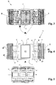
- Finally, Figure 5., schematically shows a line of fast temperature reducers, placed one close to the other to form a cooling tunnel.
-
- Also referring to the figures, it may be noticed that an improved equipment (A), particularly aiming at the ultra fast reduction of the cooked and raw food temperature, is essentially made up of a body (1), preferably in stainless steel, internally insulated and provided on the underlying part with a base, preferably also in stainless steel.
- Said body (1), perimetrically defines the equipment (A), consisting of a shape, for example parallelepiped like and not excessively developed in width, essentially subdivided in three areas, a first central one (b) and two diametrically opposed ones (c, c'), that is respectively obtained to the side of said first one (b). The central area (b) makes up the reduction chamber and is provided with a small door (2), hinged on the side, for the frontal access inside of said chamber (b), allowing the insertion of the food-holding baking pans (3) and eventually of the relative tray. In an alternative solution, always in correspondence to the reduction chamber (b), a second opening (2') may be provided, obtained on the back of the equipment. Practically, it allows the making of a modular line, consisting of a plurality of reducers (A, A', A''...) placed one after the other, substantially obtaining a tunnel for the fast and progressive reduction of the temperature.
- The reduction chamber (b) may eventually be separated from the openings (c, c') by an open inter-wall (4, 4'), centrally provided with an opening (5, 5'), in this case round shaped, to which on the other side, that is inside of at least one of the openings (c, c') at least one electric impeller (6, 6') corresponds. Said electric impeller (6, 6'), is associated to an evaporator (7, 8) which, fed by at least one compressor group and relative electric and electronic components, may be with halved and opposite single-circuit or alternatively with tandem-like opposite independent double circuit, for a better cooling safety.
- As schematically pointed out in Figure 3., dividing the necessary power on two exchangers (7, 8), one in front of the other, and ventilating both of them, and modulating their intensity, by means of ventilators (6, 6') having identical size and capacity, on the food (3) placed at the centre of the chamber (b) a whirling double flow (f, f') is created. Said flow allows to take off the heat from the food placed in the baking-pans (3), to then convey it at least towards the openings (5, 5'), thus, at first making it strongly cross the evaporator (7, 8), and then distributing it again in the reduction chamber (b). Such movement (f, f') creates a hollow (d) inside of the same chamber (b), considerably easing the temperature reduction.
- In this case, in order to optimise the yielding, the evaporators (7, 8) are of the complex type, because they are made up of a refrigerating circuit, essentially subdivided in two parts, respectively a first one (7', 8') comprising a finned piping which extends from the wall (9) to the opposite wall (9') of the areas (c, c'), and a second one (7'', 8''), occupying the space left between said first piping (7', 8') and the bottom (10), made up a non-finned piping.
- Concerning the finned piping (7', 8'), each is subdivided into three areas, separated, respectively two end ones (t') close to the side of the relative chambers (c, c') and an intermediate one (t''). The separation between said three areas (t', t'') is obtained by means of some partitions (12), respectively two for each of the finned piping (7', 8') which concern the same ones in depth. A characteristic of the two end areas (t') is that of presenting more spaced fins, that is with a different pitch, therefore a wider one, in respect to those present in the central portion (t''), consequently easing a circulation speed near the opening sides (c, c') higher than in the central part.
- The unfinned piping (7'', 8'') of the refrigerating circuit, placed at the back in respect to the finned piping (7', 8'), has the same extension of this latter, also being protracted from the wall (9) to the wall (9') of the areas (c, c'). With the purpose of increasing the air flow re-circulation speed (f, f'), perimetrically to the electric impellers (6, 6'), a deflector (11) may be provided, which substantially deviates and tightens the lateral downflow areas. As consequence, the air optimal flow obtained carries out the following cycle:
- heat removal from the treated object (3);
- going passage through the first finned piping (7', 8'), inside the evaporator (7, 8);
- passage through the unfinned piping (7'', 8''), provided on the intrados of the first one (7', 8'), in a usually empty area (c, c');
- return into the reduction chamber (b), crossing the most external pipings wall, which is at first unfinned (7'', 8'') and later finned (t').
- Again in a preferred solution, the equipment (A), may be pre-arranged to offer a series of alternative functions or in reciprocal opposition with the fast temperature reduction process. In particular, it is possible associating with it some cycle inversion valves or alternatively some batteries with electrical resistances, allowing one or more functions aiming at the heat production. Thus, the access to some treatment cycles which may concern the leavening-stop, defrosting, leavening, and softening and pasteurisation is possible.
Claims (13)
- Equipment particularly for the fast heat reduction in the cooked and raw food preservation cycles, characterised in that at least one evaporator group (7, 8) provides a refrigerating circuit comprising a first surface (7', 8') of finned pipes which transversally develops from a wall (9) to the other (9') of the relative area (c, c'), said surface (7', 8'), being in contact on the extrados with at least one electric impeller (6, 6'), while the rear part, that is the intrados, provides a second surface (7'', 8'') of the non-finned type pipes.
- Equipment for the fast heat reduction, according to claim 1., characterised in that the second surface (7'', 8'') of the unfinned type has the same extension of the first front surface of finned pipes (7', 8').
- Equipment, according to claims 1 and 2., characterised in that each finned pipe (7', 8'), is subdivided into three areas, separated, respectively two end ones (t') near to the sides of the relative chambers (c, c') and an intermediate one (t''); of which the end ones (t') have more spaced fins that is with a different pitch, resulting wider, respect to those present in the central portion (t'').
- Equipment, according to the previous claims, of the opposite flows type, particularly for a fast heat reduction in the cooked food preservation cycles, comprising a body with relative base (1), suitably insulated, said body being able to enclose at least three intercommunicating areas, a first centrally located one, making up a reduction chamber (b), in whose inside the baking-pans (3) with the food being subjected to treatment will be inserted, and two diametrically opposed ones (c, c') communicating with said first one (b), each comprising at least one evaporator (7,8) fed by at least one compressor group and a corresponding electric impeller (6,6'), using:a halved and opposite single circuit;alternatively, a tandem-like opposite independent double circuit;
characterised in that each evaporator group (7,8) provides a refrigerating circuit comprising a first surface of finned pipes (7',8') which develops transversally from one wall to another (9,9') of the relative area (c,c'), said surface being in contact on the extrados with at least one electric impeller (6,6'), while the usually empty rear part, that is the intrados, provides a second surface of pipes (7'',8'') of the non-finned type whose extension is almost equal to said first one (7',8'). - Opposite flows equipment particularly for the fast heat reduction, according to previous claims, characterised in that it provides at least three areas, a first one (b) centrally located, making up a reduction chamber, on the inside of which the baking-pans (3) with the food being subjected to treatment will be inserted, and two (c,c') diametrically opposed to said first one, each being made up of at least one evaporator (7,8) and at least a corresponding electric impeller (6,6'), intercommunicating with the reduction chamber (b).
- Opposite flows equipment particularly for the fast heat reduction, according to the previous claims, characterised in that:
the evaporators (7,8) fed by at least one compressor group, use:a halved and opposite single circuit;alternatively, a tandem-like opposite independent double circuit; - Opposite flows equipment particularly for the fast heat reduction, according to previous claims, characterised in that the two exchangers (7, 8), one in front of the other, together with the ventilators (6,6'), have alike dimensions and capacity.
- Opposite flows equipment particularly for the fast heat reduction, according to the previous claims, characterised in that on the food (3) placed at the centre of the chamber (b) a whirling and opposite double flow (f,f') is obtained.
- Opposite flows equipment particularly for the fast heat reduction, according to the previous claims, characterised in that alternatively, in correspondence to the reduction chamber (b), a second opening (2'), obtained on the equipment back, is provided, allowing the realisation of a modular line, consisting of a plurality of reducers (A, A', A''...) placed one close to the other, substantially obtaining a tunnel.
- Opposite flows equipment particularly for the fast heat reduction, according to previous claims, characterised in that perimetrically to said electric impellers (6,6'), at least one deflector (11) is provided.
- Opposite flows equipment particularly for the fast heat reduction, according to the previous claims, characterised in that it comprises some cycle inversion valves or alternatively some batteries with electrical resistances, logically co-ordinated by a programming unit, allowing one or more functions also aiming at the heat production.
- Equipment according to previous claims, characterised in that, the separation between said three areas (t',t'') is obtained by means of said partitions (12), respectively two for each of the finned pipings (7',8') which concern the same ones in depth.
- Equipment according to previous claims, characterised in that the air flow has a circulation speed near to the sides (t') of the opening (c,c') higher than in the central part (t'').
Applications Claiming Priority (2)
| Application Number | Priority Date | Filing Date | Title |
|---|---|---|---|
| IT97TV000133A IT1295490B1 (en) | 1997-10-01 | 1997-10-01 | OPPOSED FLOW EQUIPMENT, PARTICULARLY TO QUICKLY REDUCE THE HEAT IN THE PRESERVATION CYCLES OF COOKED FOOD AND |
| ITTV970133 | 1997-10-01 |
Publications (3)
| Publication Number | Publication Date |
|---|---|
| EP0907060A2 true EP0907060A2 (en) | 1999-04-07 |
| EP0907060A3 EP0907060A3 (en) | 2001-09-05 |
| EP0907060B1 EP0907060B1 (en) | 2003-11-19 |
Family
ID=11420245
Family Applications (1)
| Application Number | Title | Priority Date | Filing Date |
|---|---|---|---|
| EP98118286A Expired - Lifetime EP0907060B1 (en) | 1997-10-01 | 1998-09-28 | Opposite flows equipment, particularly for the fast heat reduction in the cooked and raw food preservation cycles even in the freezing |
Country Status (7)
| Country | Link |
|---|---|
| EP (1) | EP0907060B1 (en) |
| AT (1) | ATE254746T1 (en) |
| DE (1) | DE69819841T2 (en) |
| DK (1) | DK0907060T3 (en) |
| ES (1) | ES2212191T3 (en) |
| IT (1) | IT1295490B1 (en) |
| PT (1) | PT907060E (en) |
Cited By (4)
| Publication number | Priority date | Publication date | Assignee | Title |
|---|---|---|---|---|
| WO2002062158A2 (en) * | 2001-02-08 | 2002-08-15 | Hubert Goseling | Method for cooling meals and stirring device embodied as a heat exchanger |
| FR2861455A1 (en) * | 2003-10-23 | 2005-04-29 | Christian Muller | Thermal chamber with circulating fluid, e.g. for heating/cooling foodstuffs, has propulsion system to circulate fluid in closed loop |
| JP2013036642A (en) * | 2011-08-05 | 2013-02-21 | Altruist Co Ltd | Freezer |
| JP2015021623A (en) * | 2013-07-16 | 2015-02-02 | 板倉冷機工業株式会社 | Freezing device and freezing method |
Citations (1)
| Publication number | Priority date | Publication date | Assignee | Title |
|---|---|---|---|---|
| ITTV950054U1 (en) | 1995-10-16 | 1997-04-16 | Frigo Calor S N C Di Menegazzo | REFINEMENT OF AN APPARATUS TO QUICKLY REDUCE THE HEAT, IN PARTICULAR FOR THE CONSERVATION OF COOKED FOOD. |
Family Cites Families (6)
| Publication number | Priority date | Publication date | Assignee | Title |
|---|---|---|---|---|
| CH220296A (en) * | 1942-02-28 | 1942-03-31 | Sulzer Ag | Process for cooling respectively. Freezing of refrigerated goods and equipment for cooling or freezing for carrying out the process. |
| US3990260A (en) * | 1975-04-04 | 1976-11-09 | Eustis William E C | Low-temperature dehumidifier |
| US4981171A (en) * | 1988-09-13 | 1991-01-01 | Rite Coil, Inc. | Heat exchange coil |
| FR2663410B1 (en) * | 1990-06-19 | 1992-10-16 | Kester Ste Civile | MODULAR FAST COOLING UNIT. |
| GB9201326D0 (en) * | 1992-01-22 | 1992-03-11 | Northampton Refrigeration Comp | Refrigerated cabinet |
| WO1993019334A1 (en) * | 1992-03-20 | 1993-09-30 | Nicholas Anthony Jackman | A chiller |
-
1997
- 1997-10-01 IT IT97TV000133A patent/IT1295490B1/en active IP Right Grant
-
1998
- 1998-09-28 DE DE69819841T patent/DE69819841T2/en not_active Expired - Fee Related
- 1998-09-28 ES ES98118286T patent/ES2212191T3/en not_active Expired - Lifetime
- 1998-09-28 PT PT98118286T patent/PT907060E/en unknown
- 1998-09-28 EP EP98118286A patent/EP0907060B1/en not_active Expired - Lifetime
- 1998-09-28 DK DK98118286T patent/DK0907060T3/en active
- 1998-09-28 AT AT98118286T patent/ATE254746T1/en not_active IP Right Cessation
Patent Citations (1)
| Publication number | Priority date | Publication date | Assignee | Title |
|---|---|---|---|---|
| ITTV950054U1 (en) | 1995-10-16 | 1997-04-16 | Frigo Calor S N C Di Menegazzo | REFINEMENT OF AN APPARATUS TO QUICKLY REDUCE THE HEAT, IN PARTICULAR FOR THE CONSERVATION OF COOKED FOOD. |
Cited By (7)
| Publication number | Priority date | Publication date | Assignee | Title |
|---|---|---|---|---|
| WO2002062158A2 (en) * | 2001-02-08 | 2002-08-15 | Hubert Goseling | Method for cooling meals and stirring device embodied as a heat exchanger |
| WO2002062158A3 (en) * | 2001-02-08 | 2002-12-19 | Hubert Goseling | Method for cooling meals and stirring device embodied as a heat exchanger |
| EP1475001A2 (en) * | 2001-02-08 | 2004-11-10 | Hackman Metos OY AB | Method for preparing multiple portions of a precooked dish |
| EP1475001A3 (en) * | 2001-02-08 | 2006-04-12 | Metos Oy Ab | Method for preparing multiple portions of a precooked dish |
| FR2861455A1 (en) * | 2003-10-23 | 2005-04-29 | Christian Muller | Thermal chamber with circulating fluid, e.g. for heating/cooling foodstuffs, has propulsion system to circulate fluid in closed loop |
| JP2013036642A (en) * | 2011-08-05 | 2013-02-21 | Altruist Co Ltd | Freezer |
| JP2015021623A (en) * | 2013-07-16 | 2015-02-02 | 板倉冷機工業株式会社 | Freezing device and freezing method |
Also Published As
| Publication number | Publication date |
|---|---|
| EP0907060B1 (en) | 2003-11-19 |
| ITTV970133A0 (en) | 1997-10-01 |
| DK0907060T3 (en) | 2004-03-29 |
| EP0907060A3 (en) | 2001-09-05 |
| DE69819841D1 (en) | 2003-12-24 |
| ITTV970133A1 (en) | 1999-04-01 |
| IT1295490B1 (en) | 1999-05-12 |
| DE69819841T2 (en) | 2004-09-02 |
| ATE254746T1 (en) | 2003-12-15 |
| ES2212191T3 (en) | 2004-07-16 |
| PT907060E (en) | 2004-04-30 |
Similar Documents
| Publication | Publication Date | Title |
|---|---|---|
| US7107899B2 (en) | Spiral oven, heat delivery, enclosure and drive | |
| US9763468B2 (en) | Functional continuous rapid freezing apparatus | |
| US6976369B2 (en) | Spiral freezer, refrigeration delivery, enclosure and drive | |
| EP0907060B1 (en) | Opposite flows equipment, particularly for the fast heat reduction in the cooked and raw food preservation cycles even in the freezing | |
| US6912869B2 (en) | Helical impingement cooling and heating | |
| CN107166843A (en) | Refrigerator | |
| US3261394A (en) | Refrigeration system including means for reconstituting and preserving frozen foods and the like | |
| GB2055460A (en) | High humidity food chilling system | |
| US5067322A (en) | Refrigerator with spine fin evaporator | |
| CN111288725B (en) | Impact tunnel quick-freezing machine | |
| CN113811196A (en) | Food material freezing system and method for manufacturing frozen food material | |
| US2552396A (en) | Forced air cooling apparatus | |
| US5520006A (en) | Airflow and defrosting system for refrigeration systems and apparatus | |
| US20140260401A1 (en) | Hot product impingement freezer with impingement belt apparatus | |
| JPH05502794A (en) | Equipment for heating and cooling food | |
| JPH08303933A (en) | Defrosting device for freezing and refrigerating showcase | |
| CN203692448U (en) | Display cabinet for dessert defrosting, displaying and selling | |
| CA2080896A1 (en) | Process and device for storing foodstuffs, plants, meat and other organic substances | |
| US5214999A (en) | Zig-zag path processing facilities | |
| CN213147078U (en) | Aquatic product quick-freezing device | |
| CN108402161A (en) | Direct-cooling type spiral precooler | |
| CN108056358A (en) | A kind of frozen food processing thawing apparatus | |
| US3282331A (en) | Apparatus for reconstituting frozen foods | |
| JPH087331Y2 (en) | Continuous freezing device | |
| US1913931A (en) | Refrigerator and cooling unit therefor |
Legal Events
| Date | Code | Title | Description |
|---|---|---|---|
| PUAI | Public reference made under article 153(3) epc to a published international application that has entered the european phase |
Free format text: ORIGINAL CODE: 0009012 |
|
| AK | Designated contracting states |
Kind code of ref document: A2 Designated state(s): AT BE CH CY DE DK ES FI FR GB GR IE IT LI LU MC NL PT SE Kind code of ref document: A2 Designated state(s): AT BE CH CY DE DK ES FI FR GB GR IE LI LU MC NL PT |
|
| AX | Request for extension of the european patent |
Free format text: AL;LT;LV;MK;RO;SI |
|
| 17P | Request for examination filed |
Effective date: 19990715 |
|
| PUAL | Search report despatched |
Free format text: ORIGINAL CODE: 0009013 |
|
| AK | Designated contracting states |
Kind code of ref document: A3 Designated state(s): AT BE CH CY DE DK ES FI FR GB GR IE IT LI LU MC NL PT SE |
|
| AX | Request for extension of the european patent |
Free format text: AL;LT;LV;MK;RO;SI |
|
| AKX | Designation fees paid |
Free format text: AT BE CH CY DE DK ES FI FR GB GR IE LI LU MC NL PT |
|
| RBV | Designated contracting states (corrected) |
Designated state(s): AT BE CH DE DK ES FI FR GB GR IE LI LU MC NL PT SE |
|
| 17Q | First examination report despatched |
Effective date: 20020819 |
|
| GRAH | Despatch of communication of intention to grant a patent |
Free format text: ORIGINAL CODE: EPIDOS IGRA |
|
| GRAS | Grant fee paid |
Free format text: ORIGINAL CODE: EPIDOSNIGR3 |
|
| GRAA | (expected) grant |
Free format text: ORIGINAL CODE: 0009210 |
|
| AK | Designated contracting states |
Kind code of ref document: B1 Designated state(s): AT BE CH DE DK ES FI FR GB GR IE LI LU MC NL PT SE |
|
| REG | Reference to a national code |
Ref country code: GB Ref legal event code: FG4D |
|
| REG | Reference to a national code |
Ref country code: CH Ref legal event code: EP |
|
| REF | Corresponds to: |
Ref document number: 69819841 Country of ref document: DE Date of ref document: 20031224 Kind code of ref document: P |
|
| REG | Reference to a national code |
Ref country code: IE Ref legal event code: FG4D |
|
| REG | Reference to a national code |
Ref country code: SE Ref legal event code: TRGR |
|
| REG | Reference to a national code |
Ref country code: CH Ref legal event code: NV Representative=s name: PATENTANWALTSBUERO DIPL.-ING. S. V. KULHAVY + CO. |
|
| REG | Reference to a national code |
Ref country code: GR Ref legal event code: EP Ref document number: 20040400636 Country of ref document: GR |
|
| REG | Reference to a national code |
Ref country code: DK Ref legal event code: T3 |
|
| REG | Reference to a national code |
Ref country code: PT Ref legal event code: SC4A Free format text: AVAILABILITY OF NATIONAL TRANSLATION Effective date: 20040216 |
|
| REG | Reference to a national code |
Ref country code: ES Ref legal event code: FG2A Ref document number: 2212191 Country of ref document: ES Kind code of ref document: T3 |
|
| ET | Fr: translation filed | ||
| PLBE | No opposition filed within time limit |
Free format text: ORIGINAL CODE: 0009261 |
|
| STAA | Information on the status of an ep patent application or granted ep patent |
Free format text: STATUS: NO OPPOSITION FILED WITHIN TIME LIMIT |
|
| 26N | No opposition filed |
Effective date: 20040820 |
|
| PGFP | Annual fee paid to national office [announced via postgrant information from national office to epo] |
Ref country code: DK Payment date: 20070906 Year of fee payment: 10 |
|
| PGFP | Annual fee paid to national office [announced via postgrant information from national office to epo] |
Ref country code: MC Payment date: 20070914 Year of fee payment: 10 |
|
| PGFP | Annual fee paid to national office [announced via postgrant information from national office to epo] |
Ref country code: IE Payment date: 20070919 Year of fee payment: 10 |
|
| PGFP | Annual fee paid to national office [announced via postgrant information from national office to epo] |
Ref country code: LU Payment date: 20070926 Year of fee payment: 10 |
|
| PGFP | Annual fee paid to national office [announced via postgrant information from national office to epo] |
Ref country code: FI Payment date: 20070918 Year of fee payment: 10 Ref country code: AT Payment date: 20070930 Year of fee payment: 10 |
|
| PGFP | Annual fee paid to national office [announced via postgrant information from national office to epo] |
Ref country code: GB Payment date: 20070926 Year of fee payment: 10 |
|
| PGFP | Annual fee paid to national office [announced via postgrant information from national office to epo] |
Ref country code: SE Payment date: 20070914 Year of fee payment: 10 Ref country code: NL Payment date: 20070930 Year of fee payment: 10 Ref country code: ES Payment date: 20070928 Year of fee payment: 10 Ref country code: DE Payment date: 20071120 Year of fee payment: 10 |
|
| PGFP | Annual fee paid to national office [announced via postgrant information from national office to epo] |
Ref country code: CH Payment date: 20071211 Year of fee payment: 10 |
|
| PGFP | Annual fee paid to national office [announced via postgrant information from national office to epo] |
Ref country code: BE Payment date: 20071005 Year of fee payment: 10 |
|
| PGFP | Annual fee paid to national office [announced via postgrant information from national office to epo] |
Ref country code: FR Payment date: 20070929 Year of fee payment: 10 |
|
| PGFP | Annual fee paid to national office [announced via postgrant information from national office to epo] |
Ref country code: PT Payment date: 20070926 Year of fee payment: 10 Ref country code: GR Payment date: 20071211 Year of fee payment: 10 |
|
| BERE | Be: lapsed |
Owner name: *FRIGOCALOR S.N.C. DI MENEGAZZO GRAZIANO & C. Effective date: 20080930 |
|
| REG | Reference to a national code |
Ref country code: PT Ref legal event code: MM4A Free format text: LAPSE DUE TO NON-PAYMENT OF FEES Effective date: 20090330 |
|
| PG25 | Lapsed in a contracting state [announced via postgrant information from national office to epo] |
Ref country code: MC Free format text: LAPSE BECAUSE OF NON-PAYMENT OF DUE FEES Effective date: 20080930 |
|
| REG | Reference to a national code |
Ref country code: CH Ref legal event code: PL |
|
| REG | Reference to a national code |
Ref country code: DK Ref legal event code: EBP |
|
| GBPC | Gb: european patent ceased through non-payment of renewal fee |
Effective date: 20080928 |
|
| PG25 | Lapsed in a contracting state [announced via postgrant information from national office to epo] |
Ref country code: PT Free format text: LAPSE BECAUSE OF NON-PAYMENT OF DUE FEES Effective date: 20090330 Ref country code: NL Free format text: LAPSE BECAUSE OF NON-PAYMENT OF DUE FEES Effective date: 20090401 Ref country code: FI Free format text: LAPSE BECAUSE OF NON-PAYMENT OF DUE FEES Effective date: 20080928 |
|
| NLV4 | Nl: lapsed or anulled due to non-payment of the annual fee |
Effective date: 20090401 |
|
| REG | Reference to a national code |
Ref country code: IE Ref legal event code: MM4A |
|
| REG | Reference to a national code |
Ref country code: FR Ref legal event code: ST Effective date: 20090529 |
|
| PG25 | Lapsed in a contracting state [announced via postgrant information from national office to epo] |
Ref country code: IE Free format text: LAPSE BECAUSE OF NON-PAYMENT OF DUE FEES Effective date: 20080929 Ref country code: BE Free format text: LAPSE BECAUSE OF NON-PAYMENT OF DUE FEES Effective date: 20080930 |
|
| PG25 | Lapsed in a contracting state [announced via postgrant information from national office to epo] |
Ref country code: DE Free format text: LAPSE BECAUSE OF NON-PAYMENT OF DUE FEES Effective date: 20090401 Ref country code: AT Free format text: LAPSE BECAUSE OF NON-PAYMENT OF DUE FEES Effective date: 20080928 |
|
| PG25 | Lapsed in a contracting state [announced via postgrant information from national office to epo] |
Ref country code: LI Free format text: LAPSE BECAUSE OF NON-PAYMENT OF DUE FEES Effective date: 20080930 Ref country code: FR Free format text: LAPSE BECAUSE OF NON-PAYMENT OF DUE FEES Effective date: 20080930 Ref country code: CH Free format text: LAPSE BECAUSE OF NON-PAYMENT OF DUE FEES Effective date: 20080930 |
|
| REG | Reference to a national code |
Ref country code: ES Ref legal event code: FD2A Effective date: 20080929 |
|
| PG25 | Lapsed in a contracting state [announced via postgrant information from national office to epo] |
Ref country code: GR Free format text: LAPSE BECAUSE OF NON-PAYMENT OF DUE FEES Effective date: 20090402 Ref country code: GB Free format text: LAPSE BECAUSE OF NON-PAYMENT OF DUE FEES Effective date: 20080928 |
|
| PG25 | Lapsed in a contracting state [announced via postgrant information from national office to epo] |
Ref country code: ES Free format text: LAPSE BECAUSE OF NON-PAYMENT OF DUE FEES Effective date: 20080929 |
|
| PG25 | Lapsed in a contracting state [announced via postgrant information from national office to epo] |
Ref country code: DK Free format text: LAPSE BECAUSE OF NON-PAYMENT OF DUE FEES Effective date: 20090331 |
|
| PG25 | Lapsed in a contracting state [announced via postgrant information from national office to epo] |
Ref country code: LU Free format text: LAPSE BECAUSE OF NON-PAYMENT OF DUE FEES Effective date: 20080928 |
|
| PG25 | Lapsed in a contracting state [announced via postgrant information from national office to epo] |
Ref country code: SE Free format text: LAPSE BECAUSE OF NON-PAYMENT OF DUE FEES Effective date: 20080929 |