EP0907045B1 - Valve assembly for heating systems and water-heating apparatuses and method for its manufacture - Google Patents
Valve assembly for heating systems and water-heating apparatuses and method for its manufacture Download PDFInfo
- Publication number
- EP0907045B1 EP0907045B1 EP19970830487 EP97830487A EP0907045B1 EP 0907045 B1 EP0907045 B1 EP 0907045B1 EP 19970830487 EP19970830487 EP 19970830487 EP 97830487 A EP97830487 A EP 97830487A EP 0907045 B1 EP0907045 B1 EP 0907045B1
- Authority
- EP
- European Patent Office
- Prior art keywords
- shutter
- valve
- seat
- valve assembly
- guiding
- Prior art date
- Legal status (The legal status is an assumption and is not a legal conclusion. Google has not performed a legal analysis and makes no representation as to the accuracy of the status listed.)
- Expired - Lifetime
Links
- 238000010438 heat treatment Methods 0.000 title claims description 14
- 238000004519 manufacturing process Methods 0.000 title claims description 13
- 238000000034 method Methods 0.000 title description 3
- 239000012530 fluid Substances 0.000 claims description 45
- 239000000463 material Substances 0.000 claims description 12
- 238000007789 sealing Methods 0.000 claims description 9
- 229920001971 elastomer Polymers 0.000 claims description 8
- 229920002943 EPDM rubber Polymers 0.000 claims description 4
- 230000013011 mating Effects 0.000 claims description 4
- 238000011144 upstream manufacturing Methods 0.000 claims description 4
- NLHHRLWOUZZQLW-UHFFFAOYSA-N Acrylonitrile Chemical compound C=CC#N NLHHRLWOUZZQLW-UHFFFAOYSA-N 0.000 claims description 3
- 102000004315 Forkhead Transcription Factors Human genes 0.000 claims description 3
- 108090000852 Forkhead Transcription Factors Proteins 0.000 claims description 3
- 229920003023 plastic Polymers 0.000 claims description 2
- 239000004033 plastic Substances 0.000 claims description 2
- 229920001084 poly(chloroprene) Polymers 0.000 claims description 2
- XLYOFNOQVPJJNP-UHFFFAOYSA-N water Substances O XLYOFNOQVPJJNP-UHFFFAOYSA-N 0.000 description 13
- 238000010276 construction Methods 0.000 description 5
- 238000003754 machining Methods 0.000 description 3
- 230000007246 mechanism Effects 0.000 description 3
- 239000002184 metal Substances 0.000 description 3
- 238000013519 translation Methods 0.000 description 3
- 238000004804 winding Methods 0.000 description 3
- 238000004891 communication Methods 0.000 description 2
- 230000008878 coupling Effects 0.000 description 2
- 238000010168 coupling process Methods 0.000 description 2
- 238000005859 coupling reaction Methods 0.000 description 2
- 238000005520 cutting process Methods 0.000 description 2
- 230000005489 elastic deformation Effects 0.000 description 2
- 239000013536 elastomeric material Substances 0.000 description 2
- 238000005265 energy consumption Methods 0.000 description 2
- 230000005281 excited state Effects 0.000 description 2
- 238000003780 insertion Methods 0.000 description 2
- 230000037431 insertion Effects 0.000 description 2
- 230000002427 irreversible effect Effects 0.000 description 2
- 230000002441 reversible effect Effects 0.000 description 2
- 239000003831 antifriction material Substances 0.000 description 1
- 238000013461 design Methods 0.000 description 1
- 230000005284 excitation Effects 0.000 description 1
- 238000009434 installation Methods 0.000 description 1
- 239000007788 liquid Substances 0.000 description 1
- 230000001105 regulatory effect Effects 0.000 description 1
- 230000000717 retained effect Effects 0.000 description 1
- 239000000126 substance Substances 0.000 description 1
- 238000012360 testing method Methods 0.000 description 1
Images
Classifications
-
- F—MECHANICAL ENGINEERING; LIGHTING; HEATING; WEAPONS; BLASTING
- F16—ENGINEERING ELEMENTS AND UNITS; GENERAL MEASURES FOR PRODUCING AND MAINTAINING EFFECTIVE FUNCTIONING OF MACHINES OR INSTALLATIONS; THERMAL INSULATION IN GENERAL
- F16K—VALVES; TAPS; COCKS; ACTUATING-FLOATS; DEVICES FOR VENTING OR AERATING
- F16K11/00—Multiple-way valves, e.g. mixing valves; Pipe fittings incorporating such valves
- F16K11/02—Multiple-way valves, e.g. mixing valves; Pipe fittings incorporating such valves with all movable sealing faces moving as one unit
- F16K11/04—Multiple-way valves, e.g. mixing valves; Pipe fittings incorporating such valves with all movable sealing faces moving as one unit comprising only lift valves
- F16K11/056—Multiple-way valves, e.g. mixing valves; Pipe fittings incorporating such valves with all movable sealing faces moving as one unit comprising only lift valves with ball-shaped valve members
-
- F—MECHANICAL ENGINEERING; LIGHTING; HEATING; WEAPONS; BLASTING
- F16—ENGINEERING ELEMENTS AND UNITS; GENERAL MEASURES FOR PRODUCING AND MAINTAINING EFFECTIVE FUNCTIONING OF MACHINES OR INSTALLATIONS; THERMAL INSULATION IN GENERAL
- F16K—VALVES; TAPS; COCKS; ACTUATING-FLOATS; DEVICES FOR VENTING OR AERATING
- F16K1/00—Lift valves or globe valves, i.e. cut-off apparatus with closure members having at least a component of their opening and closing motion perpendicular to the closing faces
- F16K1/14—Lift valves or globe valves, i.e. cut-off apparatus with closure members having at least a component of their opening and closing motion perpendicular to the closing faces with ball-shaped valve member
Definitions
- the present invention relates to a valve assembly for heating systems and water-heating apparatuses.
- valve assembly of this invention is preferably, though not exclusively, intended for application to domestic heating systems and water-heating apparatuses, such as for example boilers of the so-called combined type.
- the expression 'boiler of the combined type' is used to indicate a boiler adapted to generate hot water for space heating, or primary water, as well as hot water for sanitary use.
- the invention also concerns a method of manufacturing a valve assembly as above indicated.
- valves capable of cutting off (two-way valves) or diverting (three-way valves) the fluid flowing through the circuits provided therein.
- Such valves are generally equipped with a shutter which assures the desired service by opening or closing a respective receiving seat (two-way valves) or by alternately opening and closing opposite receiving seats (three-way valves).
- the term 'fluid' is used to indicate any substance in liquid or gaseous form flowing through the valve assembly.
- the fluid referred to hereinafter is water.
- the shutter once positioned in its seat, must be adapted to shut off the fluid in a fluid-tight manner, thereby to ensure that no fluid can leak out under working pressure.
- valves provided with a shutter made of an elastomeric material and essentially spherical in shape, which shutter is mounted at the end of a pivoting arm.
- the spherical shutter is reciprocated between two opposite valve seats provided upstream of the two fluid outlet conduits by means of an external driving means.
- a shutter of this type has the advantage of being self-supported, in the sense that it provides at one time a supporting function, given by the body of elastomeric material, and a sealing function, given by its elastic properties.
- its spherical surface ensures low pressure drops in operation.
- valves of the above type are affected by a number of drawbacks which have not been remedied heretofore.
- a first drawback is related to the high manufacturing cost of such valves, essentially due to the need of carrying out an accurate machining of the sealing surfaces and to the need of providing precision-made shutter actuation mechanisms.
- the shutter of such valves indeed reiterately moves along a curvilinear travel path from one seat to the other. It follows that a fluid-tight seal can only be achieved if the shutter is exactly positioned at the very centre of its seat at the end of its stroke, such that a mating fit with the seat will provide the desired fluid-tight seal. This requires that the surfaces be machined to an accurate finish, and that particularly complicated high-precision arrangements be made for displacing the shutter.
- the manufacturing cost of conventional valves with a spherical shutter is enhanced by the constructional features that they should possess in order for the shutter to be mounted inside the valve body.
- the shutter diameter should be suitably larger than that of the valve seat(s). This involves the need of providing a service window through the valve for inserting the shutter when assembling the valve, which window must be subsequently sealingly closed with a tightly fitting cover.
- a further drawback of the above identified conventional valves is related to the high energy consumption involved by the fact that, to ensure a tight closure during the valve operation, the shutter must be held against its seat under a compressive force continuously applied by an electric motor included in the shutter driving means.
- This motor is particularly expensive, since it should be kept in an excited state, while the shutter is held against its seat, in order to ensure that the desired compressive force is exerted and the shut-off function duly provided.
- the technical problem underlying the present invention is accordingly that of providing a valve assembly which is simple in construction, inexpensive to make, and possessing such structural and functional features as to overcome the aforementioned drawbacks with regard to the prior art.
- valve assembly as defined in attached claim 1.
- substantially spherical shape' encompasses both a shutter having a fully spherical shape and a shutter formed with one or more partially rectilinear faces but having at least one curvilinear or frusto-conical sealing surface.
- a spherical shutter or to a substantially cylindrical shutter having suitably shaped, e.g. frusto-conical or curvilinear, connecting portions at the regions thereof adapted to make a fluid tight seal.
- an inexpensive valve assembly of simple construction can advantageously be provided which both ensures low pressure drops and a fluid tight seal under working pressure.
- a spherical shutter made of an elastically deformable material allows to overcome the drawbacks associated to the need of having a service window for assembling the shutter into the valve.
- a substantially spherical shutter of an elastically deformable material could be inserted into its guiding and sliding seat by compressing the same through one of the valve seats. It was found that the elastically deformable material forming the shutter may be deformed by at least 30% of its diameter or maximum cross size while still being within its elastic limit, i.e. without undergoing to plastic deformations of permanent character. This means that a substantially spherical shutter having a diameter of 23 mm, for example, can be deformed and compressed through a hole having a diameter of 16 mm.
- the elastically deformable material constituting the shutter may be selected from the group comprising: acrylonitrile rubber (NBR), polychloroprene rubber (CR), fluorinated rubber (FP), and ethylene-propylene-diene terpolymers (EPDM).
- NBR acrylonitrile rubber
- CR polychloroprene rubber
- FP fluorinated rubber
- EPDM ethylene-propylene-diene terpolymers
- the shutter guiding and sliding seat is substantially cylindrical in shape and has substantially the same diameter as the shutter.
- the shutter is guided coaxially with such seats in its reciprocating stroke towards and away from the valve seat(s), with no need for precision driving mechanisms and accurate machining of the sliding surfaces adapted to ensure a proper fit.
- the driving means comprises linear driving means arranged to act on a stem attached to the shutter, and operated by an electric motor.
- Such means are mechanically simpler and less expensive than the driving means employed in conventional valves.
- simpler engineering (less component parts) advantageously involves a reduced risk of failures.
- the shutter can be retained in its seat without keeping the motor in an excited state. Accordingly, a simpler and more economical motor can be used, and power consumption lowered.
- linear driving means allows to achieve at a very low cost, by adopting a step-by-step electric motor, a modulating valve, i.e. a valve capable of regulating the flow rate of the fluid leaving the valve assembly.
- a modulating valve i.e. a valve capable of regulating the flow rate of the fluid leaving the valve assembly.
- said at least one valve seat comprises a flaring surface formed at an opposite side with respect to an edge of sealing contact with the shutter, said flaring surface having a flaring angle ⁇ of from 15° to 40°. In this way, it is possible to facilitate the insertion of the shutter into its guiding and sliding seat.
- valve assembly further includes a plug, mounted on the valve body in a fluid-tight manner, wherethrough the shutter stem is guided for sliding movement.
- the plug is effective to isolate in a fluid-tight manner the shutter driving means, so as to keep the latter separated from the water circuit.
- the electric or mechanical portions of such means can be serviced without opening the valve, that is without the system having to be drained empty.
- a method is provided of manufacturing a valve assembly as above described which comprises the steps of:
- This method allows to manufacture a valve which is of simple construction and inexpensive, by means of a sequence of manufacturing steps which can be carried out at a low cost on large-volume production lines.
- valve assembly 1 is a three-way valve intended for installation on household water-heating apparatuses, e.g. household gas-fired boilers.
- the valve assembly 1 essentially comprises a valve body 2 in which a fluid inlet conduit 3, a first fluid outlet conduit 4a, and a second fluid outlet conduit 4b are formed.
- the shutter 6 is substantially spherical in shape, and is entirely made of acrylonitrile rubber (NBR).
- NBR acrylonitrile rubber
- a fluid inlet opening 7 is provided at the inlet end of the fluid inlet conduit 3, and a first fluid outlet opening 8a and a second fluid outlet opening 8b are respectively provided downstream of the fluid outlet conduits 4a and 4b,.
- the fluid inlet and outlet conduits 3, 4a and 4b are externally threaded for threadably coupling to the ends of threaded fittings (not shown) of respective water circuits, also not shown.
- a first opening 10a is defined within the first flowpath 9a for placing the central chamber 5 in fluid communication with the first fluid outlet conduit 4a, which opening essentially forms a respective first valve seat against which the shutter 6 can be positioned in sealing relationship.
- the first opening 10a has an edge of sealing contact 11 with the shutter 6 and, at the opposite side with respect to such edge, a flaring surface 12 having a flaring angle ⁇ of from 15° to 40°.
- a second opening 10b is defined within the second flowpath 9b for placing the central chamber 5 in fluid communication with the second fluid outlet conduit 4b, which opening essentially forms a respective second valve seat against which the shutter 6 can be positioned in sealed relationship.
- central chamber 5 and the openings 10a, 10b will be referred to hereinafter as: shutter guiding and sliding seat, and: first and second valve seats, respectively.
- the guiding and sliding seat 5 substantially has the same diameter as the shutter 6, so as to guide the same along its sliding movement in coaxial relationship with the valve seats 10a and 10b.
- the shutter 6 can be displaced within said guiding and sliding seat 5 along a substantially rectilinear travel path between first and second positions where it closes in a fluid-tight manner the first and second valve seats 10a, 10b, respectively; thus, said seats can be opened and/or closed, thereby opening and/or closing the first and second flowpaths 9a, 9b.
- the shutter 6 is secured, by means of a pair of elastic rings 13a, 13b, at one end of a stem 14 which is guided for sliding movement inside a corresponding bore 15 axially formed through a plug 16 mounted in a fluid-tight manner in a cylindrical tubular portion 17 integrally formed with the valve body 2.
- the plug 16 is received in a bore 18 axially formed in the cylindrical tubular portion 17, and is provided with a flange 19 adapted to cooperate in abutting relationship with an annular detent surface 20 internally formed in the bore 18.
- An annular gasket 21 is interposed between the plug 16 and the valve body 2.
- the plug 16 For easier sliding of the stem 14, the plug 16 includes a bush 22 made of a suitable anti-friction material which is received in a respective annular seat coaxially formed within the bore 18.
- An additional annular gasket 23, mounted adjacent to the bush 22, provides the necessary sealing with the stem 14 to prevent fluid leakouts.
- a ring 24 is arranged within a respective annular seat 25 internally formed in the bore 18.
- the cylindrical tubular portion 17 is formed with a plurality of radial holes 26 circumferentially arranged and equally spaced from one another, adapted to drain the cylindrical tubular portion 17 of any fluid that may have leaked through the plug 16.
- the valve assembly 1 further comprises means 27 for driving the shutter 6 along the guiding and sliding seat 5, which driving means is arranged to act on a spherical tailpiece 28 formed at the free end of the stem 14.
- the driving means 27 is mounted in the cylindrical tubular portion 17 and comprises an electric motor 29, conventionally powered by means of an electric supply cable 30, which is associated with a linear actuator means 31.
- the motor 29 is mounted on a baseplate 32 attached to the free end of the cylindrical tubular portion 17 by conventional fasteners 33 (e.g., screws).
- the linear actuator means 31 comprises in turn a shaft 34 having a threaded shaft portion in threaded engagement with an internally threaded metal core 35 which is placed within the windings 36 of the motor 29 and rotated therewith. This rotation is guided by a roll bearing 37 mounted at the top of motor 29.
- the threaded portion of the shaft 34 is formed with an irreversible pitch thread.
- the shaft 34 is provided at its lower end, with a fork head 38 adapted to removably receive therein the spherical tailpiece 28 of the stem 14, so that the stem 14 can be joined to the linear actuator means 31.
- the coupling of the stem 14 to the linear actuator means 31 is of a reversible type: in fact, for releasing the stem 14 from the fork head 38, it is sufficient to laterally pull the spherical tailpiece 28.
- the motor 29 and threaded portion of the shaft 34 protruding out of the cylindrical tubular portion 17 are advantageously protected by a box-type cover 39 snap fitted onto the cylindrical tubular portion 17.
- valve assembly 1 allows to selectively deliver the fluid to the water circuits associated with the first and second flowpaths 9a, 9b.
- the shutter 6 would be positioned to close the first valve seat 10a and cut off the first flowpath 9a (see Figure 1).
- the incoming fluid to the valve assembly 1 through the fluid inlet opening 7 will then flow along the second flowpath 9b and through the second outlet opening 8b to the second water circuit associated therewith.
- the shutter 6 will close the second valve seat 10b and cut off the second flowpath 9b.
- the incoming fluid to the valve assembly 1 through the fluid inlet opening 7 will then flow along the first flowpath 9a and through the first outlet opening 8a to the first water circuit associated therewith.
- the shutter 6 While moving from the first working position to the second, the shutter 6 travels along a substantially rectilinear path within its guiding and sliding seat 5.
- the movement of the shutter 6 is accomplished by exciting the windings 36 of the electric motor 29 with a supply current.
- This excitation current generates a magnetic field which rotates the metal core 35, which induces in turn a translation movement of the shaft 34, the threaded portion of which is thread-engaged in the core. This results in a vertical translation movement of the stem 14 associated to the shutter 6.
- valve assembly 1 described in the foregoing can be manufactured by the steps of:
- a substantially spherical shutter 6 having a diameter of about 23 mm can be inserted into the guiding and sliding seat 5 by compressing the same through a valve seat 10a having a diameter of about 18 mm (these being usual values in the art), without departing from the range of elastic deformation of the rubber which forms the body of the shutter 6.
- the operation involves application of a force of 50 to 80 kg by a suitable pusher, e.g. one operated by a conventional hydraulic cylinder.
- valve assembly of this invention can be readily appreciated in the light of the foregoing description.
- a first important advantage is that the rectilinear movement of the shutter within its guiding and sliding seat allows to use simpler and less expensive driving means than those used in conventional spherical shutter valves, thereby simplifying the valve construction as a whole and drastically cutting down manufacturing costs.
- a spherical shutter made of an elastically deformable material allows to overcome the drawback associated with the need of providing a service window for mounting the shutter inside the valve.
- the shutter reciprocation is guided between the seats coaxially with the latter, and no precision driving mechanisms and accurate machining of the sealing surfaces are required to ensure a properly aligned fit.
- the shutter moreover, can be held against its corresponding seat without the motor having to be kept excited. This allows to use a simpler and less expensive motor and to reduce energy consumptions.
- the shutter driving means are structurally separated from the water circuit, so that the electric or mechanical portion of such means can be serviced without opening the valve, that is, without emptying the water circuit in which the valve is incorporated.
Landscapes
- Engineering & Computer Science (AREA)
- General Engineering & Computer Science (AREA)
- Mechanical Engineering (AREA)
- Lift Valve (AREA)
- Details Of Valves (AREA)
Description
- The present invention relates to a valve assembly for heating systems and water-heating apparatuses.
- More particularly, the valve assembly of this invention is preferably, though not exclusively, intended for application to domestic heating systems and water-heating apparatuses, such as for example boilers of the so-called combined type.
- Throughout this description and the appended claims, the expression 'boiler of the combined type' is used to indicate a boiler adapted to generate hot water for space heating, or primary water, as well as hot water for sanitary use.
- The invention also concerns a method of manufacturing a valve assembly as above indicated.
- It is well known that water-heating apparatuses, and heating systems in general, require automatic valves capable of cutting off (two-way valves) or diverting (three-way valves) the fluid flowing through the circuits provided therein. Such valves are generally equipped with a shutter which assures the desired service by opening or closing a respective receiving seat (two-way valves) or by alternately opening and closing opposite receiving seats (three-way valves).
- Throughout this description and the appended claims, the term 'fluid' is used to indicate any substance in liquid or gaseous form flowing through the valve assembly. Preferably, but not exclusively, the fluid referred to hereinafter is water.
- Reference will also be made, by way of non-limitative example, to a three-way valve, it being understood that similar considerations would also apply to two-way valves.
- As is known, high efficiency and reliability in operation of the valve are the prerequisites of a valve design and selection, whether it is of the two- or three-way type.
- To this aim, the shutter, once positioned in its seat, must be adapted to shut off the fluid in a fluid-tight manner, thereby to ensure that no fluid can leak out under working pressure.
- This requirement is met by either achieving a mating engagement between the shutter and its respective valve seat(s) by means of mating surfaces thereof, and by selecting a suitable material for the shutter.
- Among the various types of valves available on the market, widespread acceptance has been gained in recent years by valves provided with a shutter made of an elastomeric material and essentially spherical in shape, which shutter is mounted at the end of a pivoting arm. In three-way valves, the spherical shutter is reciprocated between two opposite valve seats provided upstream of the two fluid outlet conduits by means of an external driving means.
- A shutter of this type has the advantage of being self-supported, in the sense that it provides at one time a supporting function, given by the body of elastomeric material, and a sealing function, given by its elastic properties. In addition, its spherical surface ensures low pressure drops in operation.
- Another valve known in the art for use in wall hydrants and possessing the features defined in the preamble of attached claim 1, is disclosed by US patent n. 4,316,481.
- While substantially achieving their objective, valves of the above type are affected by a number of drawbacks which have not been remedied heretofore.
- A first drawback is related to the high manufacturing cost of such valves, essentially due to the need of carrying out an accurate machining of the sealing surfaces and to the need of providing precision-made shutter actuation mechanisms.
- The shutter of such valves indeed reiterately moves along a curvilinear travel path from one seat to the other. It follows that a fluid-tight seal can only be achieved if the shutter is exactly positioned at the very centre of its seat at the end of its stroke, such that a mating fit with the seat will provide the desired fluid-tight seal. This requires that the surfaces be machined to an accurate finish, and that particularly complicated high-precision arrangements be made for displacing the shutter.
- The manufacturing cost of conventional valves with a spherical shutter, furthermore, is enhanced by the constructional features that they should possess in order for the shutter to be mounted inside the valve body. For a truly tight fit, in fact, the shutter diameter should be suitably larger than that of the valve seat(s). This involves the need of providing a service window through the valve for inserting the shutter when assembling the valve, which window must be subsequently sealingly closed with a tightly fitting cover.
- A further drawback of the above identified conventional valves is related to the high energy consumption involved by the fact that, to ensure a tight closure during the valve operation, the shutter must be held against its seat under a compressive force continuously applied by an electric motor included in the shutter driving means. This motor is particularly expensive, since it should be kept in an excited state, while the shutter is held against its seat, in order to ensure that the desired compressive force is exerted and the shut-off function duly provided.
- The technical problem underlying the present invention is accordingly that of providing a valve assembly which is simple in construction, inexpensive to make, and possessing such structural and functional features as to overcome the aforementioned drawbacks with regard to the prior art.
- According to a first aspect of the invention, this problem is solved by a valve assembly as defined in attached claim 1.
- Throughout the description which follows and the appended claims, the expression 'shutter of substantially spherical shape' encompasses both a shutter having a fully spherical shape and a shutter formed with one or more partially rectilinear faces but having at least one curvilinear or frusto-conical sealing surface. Thus, for example, reference will be made hereinafter to either a spherical shutter or to a substantially cylindrical shutter having suitably shaped, e.g. frusto-conical or curvilinear, connecting portions at the regions thereof adapted to make a fluid tight seal.
- Thus, according to the invention, an inexpensive valve assembly of simple construction can advantageously be provided which both ensures low pressure drops and a fluid tight seal under working pressure.
- The rectilinear travel of the shutter in its guiding and sliding seat, in fact, allows a simpler and more economical driving means to be used, resulting in a simplified valve construction and in a drastic reduction of its manufacturing costs.
- In addition, the use of a spherical shutter made of an elastically deformable material allows to overcome the drawbacks associated to the need of having a service window for assembling the shutter into the valve.
- In fact, the Applicant realised that a substantially spherical shutter of an elastically deformable material could be inserted into its guiding and sliding seat by compressing the same through one of the valve seats. It was found that the elastically deformable material forming the shutter may be deformed by at least 30% of its diameter or maximum cross size while still being within its elastic limit, i.e. without undergoing to plastic deformations of permanent character. This means that a substantially spherical shutter having a diameter of 23 mm, for example, can be deformed and compressed through a hole having a diameter of 16 mm. This means that, by applying a sufficient force, a substantially spherical shutter of an elastically deformable material can be inserted through one of the seats (usually having a diameter of 18 mm) without damaging the shutter. In this way, the valve no longer requires to be made with additional openings for the insertion of the shutter, which is advantageous both in terms of ease of manufacture and cost.
- For the purpose of this invention, the elastically deformable material constituting the shutter may be selected from the group comprising: acrylonitrile rubber (NBR), polychloroprene rubber (CR), fluorinated rubber (FP), and ethylene-propylene-diene terpolymers (EPDM). Advantageously, all these materials are adapted to withstand elastic deformations of a reversible character as the shutter is being force-fitted into its guiding and sliding seat.
- Advantageously, the shutter guiding and sliding seat is substantially cylindrical in shape and has substantially the same diameter as the shutter. In this way, the shutter is guided coaxially with such seats in its reciprocating stroke towards and away from the valve seat(s), with no need for precision driving mechanisms and accurate machining of the sliding surfaces adapted to ensure a proper fit.
- Advantageously, the driving means comprises linear driving means arranged to act on a stem attached to the shutter, and operated by an electric motor. Such means are mechanically simpler and less expensive than the driving means employed in conventional valves. In addition, simpler engineering (less component parts) advantageously involves a reduced risk of failures.
- Also, by using a threaded shaft formed with an irreversible pitch thread (to be explained in detail hereinafter), the shutter can be retained in its seat without keeping the motor in an excited state. Accordingly, a simpler and more economical motor can be used, and power consumption lowered.
- Finally, the use of linear driving means allows to achieve at a very low cost, by adopting a step-by-step electric motor, a modulating valve, i.e. a valve capable of regulating the flow rate of the fluid leaving the valve assembly.
- Advantageously, said at least one valve seat comprises a flaring surface formed at an opposite side with respect to an edge of sealing contact with the shutter, said flaring surface having a flaring angle α of from 15° to 40°. In this way, it is possible to facilitate the insertion of the shutter into its guiding and sliding seat.
- Advantageously, the valve assembly further includes a plug, mounted on the valve body in a fluid-tight manner, wherethrough the shutter stem is guided for sliding movement.
- Advantageously, the plug is effective to isolate in a fluid-tight manner the shutter driving means, so as to keep the latter separated from the water circuit. Thus, the electric or mechanical portions of such means can be serviced without opening the valve, that is without the system having to be drained empty.
- According to a second aspect of the invention, a method is provided of manufacturing a valve assembly as above described which comprises the steps of:
- providing a guiding and sliding seat for a shutter, upstream of said at least one valve seat, said guiding and sliding seat being wider than the passageway of said at least one valve seat;
- inserting a shutter of substantially spherical shape and made of an elastically deformable material in said guiding and sliding seat by forcing the same through said at least one valve seat;
- providing a shutter driving means downstream of said at least one valve seat.
-
- This method allows to manufacture a valve which is of simple construction and inexpensive, by means of a sequence of manufacturing steps which can be carried out at a low cost on large-volume production lines.
- Additional features and advantages of the present invention will be apparent from the following detailed description of a preferred embodiment thereof, given by way of non-limitative example with reference to the accompanying drawings. In the drawings:
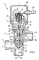
- Figure 1 is a longitudinal cross section of a valve assembly according to the invention, shown in a first operating condition;
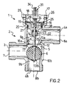
- Figure 2 is a longitudinal cross section schematically showing a detail of the valve assembly shown in Figure 1 in a second operating condition.
-
- Generally shown at 1 in the drawing figures is a valve assembly according to the invention. In particular, the valve assembly 1 is a three-way valve intended for installation on household water-heating apparatuses, e.g. household gas-fired boilers.
- The valve assembly 1 essentially comprises a valve body 2 in which a fluid inlet conduit 3, a first fluid outlet conduit 4a, and a second
fluid outlet conduit 4b are formed. - An essentially cylindrical
central chamber 5, wherein a mating-shape shutter 6 is guided for sliding movement, is formed between the fluid inlet conduit 3 and thefluid outlet conduits 4a, 4b. - In the embodiment shown, the
shutter 6 is substantially spherical in shape, and is entirely made of acrylonitrile rubber (NBR). - A fluid inlet opening 7 is provided at the inlet end of the fluid inlet conduit 3, and a first
fluid outlet opening 8a and a secondfluid outlet opening 8b are respectively provided downstream of thefluid outlet conduits 4a and 4b,. - Thus, inside the valve body 2 there are defined:
- i) a
first flowpath 9a extending between the fluid inlet opening 7 and the firstfluid outlet opening 8a, which includes: the fluid inlet conduit 3, thecentral chamber 5 and the first fluid outlet conduit 4a; and - ii) a
second flowpath 9b extending between the fluid inlet opening 7 and the secondfluid outlet opening 8b, which includes: the fluid inlet conduit 3, thecentral chamber 5 and the secondfluid outlet conduit 4b. -
- Near the
openings outlet conduits 3, 4a and 4b are externally threaded for threadably coupling to the ends of threaded fittings (not shown) of respective water circuits, also not shown. - A
first opening 10a is defined within thefirst flowpath 9a for placing thecentral chamber 5 in fluid communication with the first fluid outlet conduit 4a, which opening essentially forms a respective first valve seat against which theshutter 6 can be positioned in sealing relationship. - In particular, the
first opening 10a has an edge of sealingcontact 11 with theshutter 6 and, at the opposite side with respect to such edge, a flaringsurface 12 having a flaring angle α of from 15° to 40°. - Likewise, a
second opening 10b is defined within thesecond flowpath 9b for placing thecentral chamber 5 in fluid communication with the secondfluid outlet conduit 4b, which opening essentially forms a respective second valve seat against which theshutter 6 can be positioned in sealed relationship. - For convenience of discussion, the
central chamber 5 and theopenings - Advantageously, the guiding and sliding
seat 5 substantially has the same diameter as theshutter 6, so as to guide the same along its sliding movement in coaxial relationship with thevalve seats - The
shutter 6 can be displaced within said guiding and slidingseat 5 along a substantially rectilinear travel path between first and second positions where it closes in a fluid-tight manner the first andsecond valve seats second flowpaths - The
shutter 6 is secured, by means of a pair ofelastic rings stem 14 which is guided for sliding movement inside acorresponding bore 15 axially formed through aplug 16 mounted in a fluid-tight manner in a cylindricaltubular portion 17 integrally formed with the valve body 2. - In particular, the
plug 16 is received in abore 18 axially formed in the cylindricaltubular portion 17, and is provided with aflange 19 adapted to cooperate in abutting relationship with anannular detent surface 20 internally formed in thebore 18. Anannular gasket 21 is interposed between theplug 16 and the valve body 2. - For easier sliding of the
stem 14, theplug 16 includes abush 22 made of a suitable anti-friction material which is received in a respective annular seat coaxially formed within thebore 18. - An additional
annular gasket 23, mounted adjacent to thebush 22, provides the necessary sealing with thestem 14 to prevent fluid leakouts. - To provide for a proper positioning of the
plug 16, aring 24 is arranged within a respectiveannular seat 25 internally formed in thebore 18. - Above this
seat 25, the cylindricaltubular portion 17 is formed with a plurality ofradial holes 26 circumferentially arranged and equally spaced from one another, adapted to drain the cylindricaltubular portion 17 of any fluid that may have leaked through theplug 16. - The valve assembly 1 further comprises means 27 for driving the
shutter 6 along the guiding and slidingseat 5, which driving means is arranged to act on aspherical tailpiece 28 formed at the free end of thestem 14. - The driving means 27 is mounted in the cylindrical
tubular portion 17 and comprises anelectric motor 29, conventionally powered by means of anelectric supply cable 30, which is associated with a linear actuator means 31. In particular, themotor 29 is mounted on abaseplate 32 attached to the free end of the cylindricaltubular portion 17 by conventional fasteners 33 (e.g., screws). - The linear actuator means 31 comprises in turn a
shaft 34 having a threaded shaft portion in threaded engagement with an internally threadedmetal core 35 which is placed within thewindings 36 of themotor 29 and rotated therewith. This rotation is guided by a roll bearing 37 mounted at the top ofmotor 29. - In a preferred embodiment, the threaded portion of the
shaft 34 is formed with an irreversible pitch thread. - The
shaft 34 is provided at its lower end, with afork head 38 adapted to removably receive therein thespherical tailpiece 28 of thestem 14, so that thestem 14 can be joined to the linear actuator means 31. - Advantageously, the coupling of the
stem 14 to the linear actuator means 31 is of a reversible type: in fact, for releasing thestem 14 from thefork head 38, it is sufficient to laterally pull thespherical tailpiece 28. - The
motor 29 and threaded portion of theshaft 34 protruding out of the cylindricaltubular portion 17 are advantageously protected by a box-type cover 39 snap fitted onto the cylindricaltubular portion 17. - The operation of the valve assembly 1 described above allows to selectively deliver the fluid to the water circuits associated with the first and
second flowpaths - Assume for simplicity that the fluid is to be delivered to the water circuit associated to the
flowpath 9b. In this case, theshutter 6 would be positioned to close thefirst valve seat 10a and cut off thefirst flowpath 9a (see Figure 1). The incoming fluid to the valve assembly 1 through the fluid inlet opening 7 will then flow along thesecond flowpath 9b and through the second outlet opening 8b to the second water circuit associated therewith. - Assume now that the fluid is to be delivered to the water circuit associated to the
flowpath 9a. For this to take place, theshutter 6 must be shifted to a second operating position, such as that shown in Figure 2. - In this position, the
shutter 6 will close thesecond valve seat 10b and cut off thesecond flowpath 9b. The incoming fluid to the valve assembly 1 through the fluid inlet opening 7 will then flow along thefirst flowpath 9a and through the first outlet opening 8a to the first water circuit associated therewith. - While moving from the first working position to the second, the
shutter 6 travels along a substantially rectilinear path within its guiding and slidingseat 5. - The movement of the
shutter 6 is accomplished by exciting thewindings 36 of theelectric motor 29 with a supply current. This excitation current generates a magnetic field which rotates themetal core 35, which induces in turn a translation movement of theshaft 34, the threaded portion of which is thread-engaged in the core. This results in a vertical translation movement of thestem 14 associated to theshutter 6. - By reversing the current flow through the
windings 36, and along therewith, the direction in which themetal core 35 is rotated, the direction of theshutter 6 translation movement can be quite simply reversed. - The valve assembly 1 described in the foregoing can be manufactured by the steps of:
- providing the guiding and sliding
seat 5 for theshutter 6 upstream of thevalve seat 10a, said guiding and slidingseat 5 having a width wider than that of the passageway of thevalve seat 10a; - inserting the
shutter 6 into the guiding and slidingseat 5 by compressing the same through thevalve seat 10a; - providing the driving means 27 for the
shutter 6 downstream of thevalve seat 10a. -
- Practical tests have shown that the
shutter 6 can be compressed through theseat 10a by applying an appropriate force and without damaging theshutter 6 nor the seat. - Thus, for example, a substantially
spherical shutter 6 having a diameter of about 23 mm can be inserted into the guiding and slidingseat 5 by compressing the same through avalve seat 10a having a diameter of about 18 mm (these being usual values in the art), without departing from the range of elastic deformation of the rubber which forms the body of theshutter 6. - The operation involves application of a force of 50 to 80 kg by a suitable pusher, e.g. one operated by a conventional hydraulic cylinder.
- Conversely, since the working differential pressures designed for the valve 1 would amount to less than 1 bar --meaning, for a seat having a diameter of 18 mm, maximum working forces of less than about 2.5 kg, that is largely smaller than said compressive force -- there exists no practical possibility for the
shutter 6 to jam within, or even worse, extrude through one of thevalve seats - The numerous advantages afforded by the valve assembly of this invention can be readily appreciated in the light of the foregoing description.
- A first important advantage is that the rectilinear movement of the shutter within its guiding and sliding seat allows to use simpler and less expensive driving means than those used in conventional spherical shutter valves, thereby simplifying the valve construction as a whole and drastically cutting down manufacturing costs.
- Furthermore, the use of a spherical shutter made of an elastically deformable material, besides providing an adequately tight fit and low pressure drops, allows to overcome the drawback associated with the need of providing a service window for mounting the shutter inside the valve.
- Also, the shutter reciprocation is guided between the seats coaxially with the latter, and no precision driving mechanisms and accurate machining of the sealing surfaces are required to ensure a properly aligned fit.
- The shutter, moreover, can be held against its corresponding seat without the motor having to be kept excited. This allows to use a simpler and less expensive motor and to reduce energy consumptions.
- In addition, by using linear actuator means and a step-by-step motor, it is possible to manufacture a modulating valve at a very low cost.
- Finally, the shutter driving means are structurally separated from the water circuit, so that the electric or mechanical portion of such means can be serviced without opening the valve, that is, without emptying the water circuit in which the valve is incorporated.
Claims (8)
- A valve assembly for heating systems and water-heating apparatuses, comprising:characterised in that the shutter (6) can be inserted into said guiding and sliding seat (5) by compressing the shutter (6) through one of said valve seats (10a,10b) and in that the respective sizes of the shutter (6) and of said at least one seat (10a,10b) are such that the shutter (6) can be inserted through said at least one valve seat (10a,10b) without undergoing permanent plastic deformations.a valve body (2) wherein a fluid inlet opening (7) and at least one fluid outlet opening (8a,8b) are defined;a flowpath (9a,9b) extending between said fluid inlet opening (7) and said at least one fluid outlet opening (8a,8b);at least one valve seat (10a,10b) formed in said valve body (2) and positioned in the flowpath (9a,9b);a shutter (6) of substantially spherical shape, made of an elastically deformable material, reciprocable by a driving means (27) between a first and a second position whereat it respectively opens and closes said at least one valve seat (10a,10b), said shutter (6) being guided for sliding movement along a substantially rectilinear travel path in a respective guiding and sliding seat (5) having a substantially mating shape, formed in said valve body (2);
- A valve assembly according to Claim 1, wherein the guiding and sliding seat (5) for the shutter (6) is substantially cylindrical in shape and has substantially the same diameter as the shutter (6).
- A valve assembly according to Claim 1, wherein the driving means (27) comprises a linear actuator means (31) arranged to act on a stem (14) attached to the shutter (6) and operated by an electric motor (29).
- A valve assembly according to Claim 1, wherein the shutter (6) is made of a material selected from the group comprising: acrylonitrile rubber (NBR), polychloroprene rubber (CR), fluorinated rubber (FP), and ethylene-propylene-diene terpolymers (EPDM).
- A valve assembly according to Claim 1, wherein said at least one valve seat (10a,10b) comprises a flaring surface (12), formed at an opposite side with respect to an edge of sealing contact (11) with the shutter (6), said flaring surface having a flaring angle (α) of from 15° to 40°.
- A valve assembly according to Claim 1, further comprising a plug (16), mounted in a fluid-tight manner inside a cylindrical tubular portion (17) integrally formed with said valve body (2), wherethrough the shutter (6) stem (14) is guided for sliding movement, said plug (16) being adapted to isolate in a fluid-tight manner the driving means (27) of the shutter (6).
- A valve assembly according to Claim 3, wherein the linear actuator means (31) comprises a shaft (34) provided with a fork head (38) adapted to removably receive a spherical tailpiece (28) formed on a free end of the stem (14).
- A method of manufacturing a valve assembly for heating systems and water-heating apparatuses according to claim 1, comprising the steps of:providing a guiding and sliding seat (5) for a shutter (6), upstream of said at least one valve seat (10a,10b), said guiding and sliding seat (5) being wider than the passageway of said at least one valve seat (10a,10b);inserting a shutter (6) of substantially spherical shape and made of an elastically deformable material in said guiding and sliding seat (5) by compressing the same through said at least one valve seat (10a, 10b);providing driving means (27) for the shutter (6) downstream of said at least one valve seat (10a,10b).
Priority Applications (3)
| Application Number | Priority Date | Filing Date | Title |
|---|---|---|---|
| ES97830487T ES2183117T3 (en) | 1997-10-02 | 1997-10-02 | VALVE ASSEMBLY FOR HEATING SYSTEMS AND WATER HEATING EQUIPMENT AND MANUFACTURING PROCEDURE. |
| EP19970830487 EP0907045B1 (en) | 1997-10-02 | 1997-10-02 | Valve assembly for heating systems and water-heating apparatuses and method for its manufacture |
| DE1997615199 DE69715199T2 (en) | 1997-10-02 | 1997-10-02 | Valve arrangement for heating systems and water heaters and process for their manufacture |
Applications Claiming Priority (1)
| Application Number | Priority Date | Filing Date | Title |
|---|---|---|---|
| EP19970830487 EP0907045B1 (en) | 1997-10-02 | 1997-10-02 | Valve assembly for heating systems and water-heating apparatuses and method for its manufacture |
Publications (2)
| Publication Number | Publication Date |
|---|---|
| EP0907045A1 EP0907045A1 (en) | 1999-04-07 |
| EP0907045B1 true EP0907045B1 (en) | 2002-09-04 |
Family
ID=8230793
Family Applications (1)
| Application Number | Title | Priority Date | Filing Date |
|---|---|---|---|
| EP19970830487 Expired - Lifetime EP0907045B1 (en) | 1997-10-02 | 1997-10-02 | Valve assembly for heating systems and water-heating apparatuses and method for its manufacture |
Country Status (3)
| Country | Link |
|---|---|
| EP (1) | EP0907045B1 (en) |
| DE (1) | DE69715199T2 (en) |
| ES (1) | ES2183117T3 (en) |
Families Citing this family (5)
| Publication number | Priority date | Publication date | Assignee | Title |
|---|---|---|---|---|
| DE19946654B4 (en) * | 1999-09-29 | 2005-10-27 | Agilent Technologies, Inc. (n.d.Ges.d.Staates Delaware), Palo Alto | Valve for liquid separation technology |
| AT410830B (en) * | 2001-03-23 | 2003-08-25 | Vaillant Gmbh | SWITCHING |
| EP1388696A1 (en) | 2002-08-08 | 2004-02-11 | Giorgio Scanferla | Valve assembly with a shutter for heating systems and water-heating apparatus |
| EP1580468A1 (en) * | 2004-03-22 | 2005-09-28 | Giorgio Scanferla | Linearly driven valve |
| EP4264094A1 (en) * | 2020-12-18 | 2023-10-25 | ECO Holding 1 GmbH | Proportional valve assembly for refrigerant |
Family Cites Families (8)
| Publication number | Priority date | Publication date | Assignee | Title |
|---|---|---|---|---|
| FR596511A (en) * | 1924-04-14 | 1925-10-26 | Improvements in valves | |
| FR1420815A (en) * | 1965-01-04 | 1965-12-10 | Improvements made to valve shut-off devices, especially for pressurized liquids | |
| FR2067404A5 (en) * | 1969-11-03 | 1971-08-20 | Jurdyc Marius | |
| FR2128931A5 (en) * | 1971-03-09 | 1972-10-27 | Peugeot & Renault | |
| FR2128964A5 (en) * | 1971-03-10 | 1972-10-27 | Knapp Mikrohydraulik Gmbh | |
| US4316481A (en) * | 1980-04-11 | 1982-02-23 | Woodford Manufacturing Company | Wall hydrant |
| US4970484A (en) * | 1987-12-04 | 1990-11-13 | Vernay Laboratories, Inc. | Composite elastomer-tipped tubular metallic device for armature and needle valve applications |
| FR2719101B1 (en) * | 1994-04-25 | 1996-06-28 | Chaffoteaux Et Maury | Improvements to electrically operated three-way valves. |
-
1997
- 1997-10-02 DE DE1997615199 patent/DE69715199T2/en not_active Expired - Fee Related
- 1997-10-02 EP EP19970830487 patent/EP0907045B1/en not_active Expired - Lifetime
- 1997-10-02 ES ES97830487T patent/ES2183117T3/en not_active Expired - Lifetime
Also Published As
| Publication number | Publication date |
|---|---|
| EP0907045A1 (en) | 1999-04-07 |
| DE69715199D1 (en) | 2002-10-10 |
| ES2183117T3 (en) | 2003-03-16 |
| DE69715199T2 (en) | 2003-07-31 |
Similar Documents
| Publication | Publication Date | Title |
|---|---|---|
| EP0907046B1 (en) | Improved valve assembly for heating systems and water-heating apparatuses | |
| EP0039319B2 (en) | Double seat valve | |
| US4201366A (en) | Bellows valve | |
| FI74336C (en) | Eccentric valve with self-centering seat. | |
| EP0202883B1 (en) | Bellows valve | |
| EP3058256B1 (en) | Floating ball valve seal | |
| WO2009032569A1 (en) | High-temperature ball valve seal | |
| MX2013014917A (en) | Multi-port normally open modular valve with thread-in seat. | |
| US6701959B1 (en) | High flow rate balanced poppet valve | |
| AU2008276194A1 (en) | Methods and apparatus to align a seat ring in a valve | |
| EP0907045B1 (en) | Valve assembly for heating systems and water-heating apparatuses and method for its manufacture | |
| EP1180626B1 (en) | Valve and method for forming a valve | |
| AU2004203647B2 (en) | Joint-type coaxial connection | |
| EP0077396A1 (en) | Improved snap-on shut off valve | |
| EP0447707A1 (en) | Valve with removable insert | |
| EP0134866A2 (en) | On-off valve | |
| US7108011B1 (en) | Self closing mixing cartridge for single handle cartridge type faucet | |
| US4659061A (en) | Seal ring shutoff stem tip | |
| US6382239B1 (en) | Leak-detecting diverter valve | |
| US7201188B2 (en) | Fluted reciprocating ball valve | |
| US5901945A (en) | Two-way valve for pipelines | |
| WO2016020745A1 (en) | Solenoid valve with in-line balancing rod | |
| CN111692371B (en) | Long-life ball valve | |
| EP1718891B1 (en) | Leak-resistant solenoid valves | |
| KR200334648Y1 (en) | Segment plug type double eccentric metal seat ball valve |
Legal Events
| Date | Code | Title | Description |
|---|---|---|---|
| PUAI | Public reference made under article 153(3) epc to a published international application that has entered the european phase |
Free format text: ORIGINAL CODE: 0009012 |
|
| AK | Designated contracting states |
Kind code of ref document: A1 Designated state(s): AT BE CH DE DK ES FI FR LI Kind code of ref document: A1 Designated state(s): DE ES FR GB IT NL |
|
| AX | Request for extension of the european patent |
Free format text: AL;LT;LV;RO;SI |
|
| AKX | Designation fees paid |
Free format text: AT BE CH DE DK ES FI FR LI |
|
| 17P | Request for examination filed |
Effective date: 19991009 |
|
| RBV | Designated contracting states (corrected) |
Designated state(s): DE ES FR GB IT NL |
|
| RBV | Designated contracting states (corrected) |
Designated state(s): DE ES FR GB IT NL |
|
| 17Q | First examination report despatched |
Effective date: 20010323 |
|
| GRAG | Despatch of communication of intention to grant |
Free format text: ORIGINAL CODE: EPIDOS AGRA |
|
| GRAG | Despatch of communication of intention to grant |
Free format text: ORIGINAL CODE: EPIDOS AGRA |
|
| GRAH | Despatch of communication of intention to grant a patent |
Free format text: ORIGINAL CODE: EPIDOS IGRA |
|
| GRAH | Despatch of communication of intention to grant a patent |
Free format text: ORIGINAL CODE: EPIDOS IGRA |
|
| GRAA | (expected) grant |
Free format text: ORIGINAL CODE: 0009210 |
|
| GRAH | Despatch of communication of intention to grant a patent |
Free format text: ORIGINAL CODE: EPIDOS IGRA |
|
| AK | Designated contracting states |
Kind code of ref document: B1 Designated state(s): DE ES FR GB IT NL |
|
| REG | Reference to a national code |
Ref country code: GB Ref legal event code: FG4D |
|
| REF | Corresponds to: |
Ref document number: 69715199 Country of ref document: DE Date of ref document: 20021010 |
|
| RAP2 | Party data changed (patent owner data changed or rights of a patent transferred) |
Owner name: SCANFERLA, GIORGIO |
|
| RIN2 | Information on inventor provided after grant (corrected) |
Free format text: SCANFERLA, GIORGIO |
|
| NLT2 | Nl: modifications (of names), taken from the european patent patent bulletin |
Owner name: SCANFERLA, GIORGIO |
|
| ET | Fr: translation filed | ||
| REG | Reference to a national code |
Ref country code: ES Ref legal event code: FG2A Ref document number: 2183117 Country of ref document: ES Kind code of ref document: T3 |
|
| PLBE | No opposition filed within time limit |
Free format text: ORIGINAL CODE: 0009261 |
|
| STAA | Information on the status of an ep patent application or granted ep patent |
Free format text: STATUS: NO OPPOSITION FILED WITHIN TIME LIMIT |
|
| 26N | No opposition filed |
Effective date: 20030605 |
|
| PGFP | Annual fee paid to national office [announced via postgrant information from national office to epo] |
Ref country code: NL Payment date: 20081024 Year of fee payment: 12 |
|
| PGFP | Annual fee paid to national office [announced via postgrant information from national office to epo] |
Ref country code: DE Payment date: 20081201 Year of fee payment: 12 |
|
| PGFP | Annual fee paid to national office [announced via postgrant information from national office to epo] |
Ref country code: ES Payment date: 20081027 Year of fee payment: 12 |
|
| PGFP | Annual fee paid to national office [announced via postgrant information from national office to epo] |
Ref country code: IT Payment date: 20081007 Year of fee payment: 12 |
|
| PGFP | Annual fee paid to national office [announced via postgrant information from national office to epo] |
Ref country code: FR Payment date: 20081018 Year of fee payment: 12 |
|
| PGFP | Annual fee paid to national office [announced via postgrant information from national office to epo] |
Ref country code: GB Payment date: 20081029 Year of fee payment: 12 |
|
| REG | Reference to a national code |
Ref country code: NL Ref legal event code: V1 Effective date: 20100501 |
|
| REG | Reference to a national code |
Ref country code: FR Ref legal event code: ST Effective date: 20100630 |
|
| PG25 | Lapsed in a contracting state [announced via postgrant information from national office to epo] |
Ref country code: NL Free format text: LAPSE BECAUSE OF NON-PAYMENT OF DUE FEES Effective date: 20100501 Ref country code: FR Free format text: LAPSE BECAUSE OF NON-PAYMENT OF DUE FEES Effective date: 20091102 Ref country code: DE Free format text: LAPSE BECAUSE OF NON-PAYMENT OF DUE FEES Effective date: 20100501 |
|
| PG25 | Lapsed in a contracting state [announced via postgrant information from national office to epo] |
Ref country code: GB Free format text: LAPSE BECAUSE OF NON-PAYMENT OF DUE FEES Effective date: 20091002 |
|
| PG25 | Lapsed in a contracting state [announced via postgrant information from national office to epo] |
Ref country code: IT Free format text: LAPSE BECAUSE OF NON-PAYMENT OF DUE FEES Effective date: 20091002 |
|
| REG | Reference to a national code |
Ref country code: ES Ref legal event code: FD2A Effective date: 20110408 |
|
| PG25 | Lapsed in a contracting state [announced via postgrant information from national office to epo] |
Ref country code: ES Free format text: LAPSE BECAUSE OF NON-PAYMENT OF DUE FEES Effective date: 20110328 |
|
| PG25 | Lapsed in a contracting state [announced via postgrant information from national office to epo] |
Ref country code: ES Free format text: LAPSE BECAUSE OF NON-PAYMENT OF DUE FEES Effective date: 20091003 |