EP0906869B1 - Cap/closure having a venting mechanism for use with centrifuge containers - Google Patents
Cap/closure having a venting mechanism for use with centrifuge containers Download PDFInfo
- Publication number
- EP0906869B1 EP0906869B1 EP98307210A EP98307210A EP0906869B1 EP 0906869 B1 EP0906869 B1 EP 0906869B1 EP 98307210 A EP98307210 A EP 98307210A EP 98307210 A EP98307210 A EP 98307210A EP 0906869 B1 EP0906869 B1 EP 0906869B1
- Authority
- EP
- European Patent Office
- Prior art keywords
- stopper member
- cap assembly
- container
- channel
- stopper
- Prior art date
- Legal status (The legal status is an assumption and is not a legal conclusion. Google has not performed a legal analysis and makes no representation as to the accuracy of the status listed.)
- Expired - Lifetime
Links
Images

Classifications
-
- B—PERFORMING OPERATIONS; TRANSPORTING
- B01—PHYSICAL OR CHEMICAL PROCESSES OR APPARATUS IN GENERAL
- B01L—CHEMICAL OR PHYSICAL LABORATORY APPARATUS FOR GENERAL USE
- B01L3/00—Containers or dishes for laboratory use, e.g. laboratory glassware; Droppers
- B01L3/50—Containers for the purpose of retaining a material to be analysed, e.g. test tubes
- B01L3/508—Rigid containers without fluid transport within
- B01L3/5082—Test tubes per se
- B01L3/50825—Closing or opening means, corks, bungs
-
- B—PERFORMING OPERATIONS; TRANSPORTING
- B65—CONVEYING; PACKING; STORING; HANDLING THIN OR FILAMENTARY MATERIAL
- B65D—CONTAINERS FOR STORAGE OR TRANSPORT OF ARTICLES OR MATERIALS, e.g. BAGS, BARRELS, BOTTLES, BOXES, CANS, CARTONS, CRATES, DRUMS, JARS, TANKS, HOPPERS, FORWARDING CONTAINERS; ACCESSORIES, CLOSURES, OR FITTINGS THEREFOR; PACKAGING ELEMENTS; PACKAGES
- B65D51/00—Closures not otherwise provided for
- B65D51/16—Closures not otherwise provided for with means for venting air or gas
- B65D51/1672—Closures not otherwise provided for with means for venting air or gas whereby venting occurs by manual actuation of the closure or other element
- B65D51/1688—Venting occurring during initial closing or opening of the container, by means of a passage for the escape of gas between the closure and the lip of the container mouth, e.g. interrupted threads
-
- B—PERFORMING OPERATIONS; TRANSPORTING
- B65—CONVEYING; PACKING; STORING; HANDLING THIN OR FILAMENTARY MATERIAL
- B65D—CONTAINERS FOR STORAGE OR TRANSPORT OF ARTICLES OR MATERIALS, e.g. BAGS, BARRELS, BOTTLES, BOXES, CANS, CARTONS, CRATES, DRUMS, JARS, TANKS, HOPPERS, FORWARDING CONTAINERS; ACCESSORIES, CLOSURES, OR FITTINGS THEREFOR; PACKAGING ELEMENTS; PACKAGES
- B65D51/00—Closures not otherwise provided for
- B65D51/18—Arrangements of closures with protective outer cap-like covers or of two or more co-operating closures
-
- B—PERFORMING OPERATIONS; TRANSPORTING
- B65—CONVEYING; PACKING; STORING; HANDLING THIN OR FILAMENTARY MATERIAL
- B65D—CONTAINERS FOR STORAGE OR TRANSPORT OF ARTICLES OR MATERIALS, e.g. BAGS, BARRELS, BOTTLES, BOXES, CANS, CARTONS, CRATES, DRUMS, JARS, TANKS, HOPPERS, FORWARDING CONTAINERS; ACCESSORIES, CLOSURES, OR FITTINGS THEREFOR; PACKAGING ELEMENTS; PACKAGES
- B65D2251/00—Details relating to container closures
- B65D2251/0003—Two or more closures
- B65D2251/0006—Upper closure
- B65D2251/0015—Upper closure of the 41-type
-
- B—PERFORMING OPERATIONS; TRANSPORTING
- B65—CONVEYING; PACKING; STORING; HANDLING THIN OR FILAMENTARY MATERIAL
- B65D—CONTAINERS FOR STORAGE OR TRANSPORT OF ARTICLES OR MATERIALS, e.g. BAGS, BARRELS, BOTTLES, BOXES, CANS, CARTONS, CRATES, DRUMS, JARS, TANKS, HOPPERS, FORWARDING CONTAINERS; ACCESSORIES, CLOSURES, OR FITTINGS THEREFOR; PACKAGING ELEMENTS; PACKAGES
- B65D2251/00—Details relating to container closures
- B65D2251/0003—Two or more closures
- B65D2251/0068—Lower closure
- B65D2251/0075—Lower closure of the 39-type
-
- Y—GENERAL TAGGING OF NEW TECHNOLOGICAL DEVELOPMENTS; GENERAL TAGGING OF CROSS-SECTIONAL TECHNOLOGIES SPANNING OVER SEVERAL SECTIONS OF THE IPC; TECHNICAL SUBJECTS COVERED BY FORMER USPC CROSS-REFERENCE ART COLLECTIONS [XRACs] AND DIGESTS
- Y10—TECHNICAL SUBJECTS COVERED BY FORMER USPC
- Y10S—TECHNICAL SUBJECTS COVERED BY FORMER USPC CROSS-REFERENCE ART COLLECTIONS [XRACs] AND DIGESTS
- Y10S215/00—Bottles and jars
- Y10S215/03—Medical
Definitions
- the present invention pertains to the field of centrifugation. Specifically, the present invention pertains to an improved capping assembly for removable sample-holding containers employed in centrifuges.
- Centrifuges are commonly used in medical and biological industries for separating and purifying materials of differing densities, such as viruses, bacteria, cells and proteins.
- a centrifuge includes a rotor and a container to support a sample undergoing centrifugation.
- the rotor is designed to hold the sample container while it spins up to tens of thousands of revolutions per minute.
- a cover is placed onto the container so as to provide a fluid-tight seal therebetween.
- U.S. Pat. No. 718,643 to Lees et al. discloses a sealing-jar for preserving articles of food, Fig. 1, including a body of a receptacle (a), a recess (b), a cover (c), a flat flange (d), a circular down-turned rib (e), and a rubber gasket (f).
- a seal is achieved by the gasket (f) fitting around the cover (c), beneath the flange (d), so as to bear against the recess (b), but this seal is easily compromised by centrifugal forces.
- Australian Pat. No. 4247/26 to Lucke et al. discloses an apparatus for sealing bottles and jars, Figs. 1-3, containing a domed disc stopper 8 having a downwardly projecting wall 9 near its outer edge.
- the wall 9 is inclined to match the seating 7 at the top of a rigid neck 5 of a jar or bottle.
- a rigid cap 12 has internal screw-threads 6 that are designed to thread onto the neck 5.
- a resilient ring 10 fits into an annular groove in the face of the stopper, col. 3 lines 4-8. The resilient ring 10 seats against the neck 5 by the cap 12 pressing against the stopper 8.
- U.S. Pat. No. 3,924,772 to Magnani et al. discloses an airtight container cap, Figs. 1-3, containing a ring-nut 1 have an upper circular hole 2, a slot 3 on the side surface thereof and threads 4; a jar 7 with a threaded neck 6; glass stopper 8 having one groove 9 in the upper portion a second groove 10 in the lower portion and a shoulder 12; and a circular gasket 11. The circular gasket 11 is positioned within groove 10 of the glass stopper 8. The glass stopper 8 is then mounted inside of ring-nut 1 through hole 2. Ring-nut 1 is then threaded onto the neck 6 of a jar 7, forming a hermetic seal.
- U.S. Pat. No. 4,844,273 to Hawkins et al. discloses a closure with enhanced sealing for a container, Figs. 1-3, comprising a container neck lip 30 and a cap 18 having an inner skirt 24, a top 20 and a depending coaxial outer skirt 22.
- the outer skirt has internal threads 26 for engaging the complementary external threads 28 of the container neck.
- the inner skirt 24 has an interference fit with the inside of the container neck lip 30, thus, forming one element of the enhanced seal.
- a bead 32 projects inwardly from the depending skirt 22 and provides the second element of the enhanced seal by maintaining peripheral contact against the outside of the container neck lip 30.
- An o-ring 34 is positioned between the outer and inner skirts, 22 and 24, respectively, and becomes compressed between the top 20 and the container lip 30 to maintain a hermetic seal while the cap 18 is threaded on the container neck 12.
- the rigid inner skirt firmly presses against the inside of lip 30 and co-acts with the inwardly directed bead 32 maintaining peripheral contact with the outside lip 30, which helps to maintain the hermetic seal by retaining the o-ring 34 in its compressed state.
- U.S. Pat. No. 5,291,783 to Hall discloses a tube 10 for use in a fixed angle centrifuge rotor having indicia 20 thereon indicating the level to which the tube may be filled with liquid without risk of spillage due to meniscus re-orientating.
- U.S. Pat. No. 5,325,977 to Haynes et al. discloses a vented closure for a capillary tube assembly 10.
- the assembly 10 includes a capillary tube 12 having a bore extending therethrough and a cap 14 slidably mounted to on end of the tube 12.
- the cap 14 includes an enlarged head 16 and a substantially cylindrical body 18.
- One or more vent grooves 20 are formed into the body which allows air to escape when the cap 14 is in a first slidable position.
- the groove 20 typically extends parallel to the longitudinal axis of the cylindrical body 18.
- U.S. Pat. No. 5,458,252 discloses an invertible pressure-responsive sealing cap 1 for attachment to a container 2 having a mouth 4 with an outwardly facing threaded portion 12.
- the mouth 4 has an inner cylindrical sealing surface 6.
- the cap 1 has a threaded portion 3 disposed on a cap skirt 5, with the threaded portion 3 facing inwardly toward a cap axis 7.
- a central dome portion 9 is symmetrically disposed about the cap axis 7 and extends outwardly therefrom, terminating in an annular portion 11.
- the dome portion 9 is initially concave and extends into the mouth 4 of the container 2.
- the interface of the dome portion 9 and the annular portion 11 define a first flexure area 17.
- a sealing portion 13 is disposed about the annular portion 11, defining a second flexure area 21 thereat.
- the sealing portion 13 includes an outwardly facing cylindrical surface 23.
- the cap 1 is mated to the container 2 and pressure build-up therein causes the dome portion 9 to flatten, increasing the sealing force between the sealing surfaces 23 and 6.
- a drawback with the aforementioned containers is that the fluid-tight integrity of the seals is compromised by samples egressing therethrough during centrifugation, which has led to the development of seals which employ centrifugal force to drive a cap or plug against a container.
- a capping assembly for a centrifuge container that is capable of maintaining a tight seal during a centrifugation run while at the same time is capable of easily releasing a vacuum that may develop within the container during the run. It is desirable that such a capping assembly be manufactured with minimum parts and easily maintained during its useful life.
- GB1174337 discloses an applicator for fluids or pastes stored in the hollow interior of the applicator body whose upper end is closed by a web or stopper having a central hole through which the fluid or paste is dispensed.
- the central hole holds a valve member that is normally held outwardly away from the web or stopper by radially extending resilient feet so as to open the central hole to the passage of the fluids or pastes.
- the web or stopper and its valve member are covered by a thick resilient two-layer porous cover through which the fluid or paste is dispensed when the applicator is uncapped.
- a cap assembly for a centrifuge container comprising a stopper member adapted to seal an open end of said container, said stopper member having opposed top and bottom surfaces, a closeable channel extending through the centre of said stopper member between said stopper member top and bottom surfaces, said channel having an upper orifice opening through said stopper member top surface and a lower orifice opening through said stopper member bottom surface; and a lid member adapted to removably contact said stopper member when said stopper member is received in said open end of said container, said lid member having opposed top and bottom surfaces, said lid member bottom surface having downwardly depending ribs mutually converging into a downwardly depending central boss providing a central contact area that contacts said stopper member top surface around said upper orifice opening to close said channel when said stopper member is received in said open end of said container and said lid member is engaged with the stoppered end of said container to cause the central contact area of said central boss to contact and press down upon said stopper member top surface around said upper
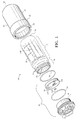
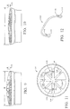
- Fig. 1 is an exploded perspective view of the capping assembly employed in a dual-vessel removable sample-holding centrifuge container, in accord with the present invention.
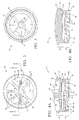
- Fig. 2 is a perspective view showing a dual-vessel removable sample-holding centrifuge container of Fig. 1 placed in a centrifuge rotor in accord with the present invention.
- Fig. 3 is a top down view of a lid shown in Fig 1.
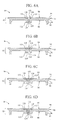
- Figs. 4A and 4B are cross-sectional views of the lid shown in Fig. 3 taken along view lines A-A and B-B respectively.
- Fig. 5 is a bottom view of the lid shown in Fig 3.
- Figs. 6A-6D are cross-sectional views of various embodiments of a stopper or plug shown in Fig.1.
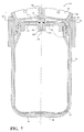
- Fig. 7 is a cross-sectional view of the container shown in Fig. 1, with the capping assembly shown in a final seating position.
- Figs. 8A and 8B are detailed views of the container shown in Fig.7.
- Fig. 9 is a side view of the lid shown in Fig 3 when at rest.
- Fig. 10 is the lid shown in Fig. 9 when subjected to centrifugal loading.
- Fig. 11 is a top down view of the lid shown in Fig. 3, having a handle disposed thereon.
- Fig. 12 is perspective view of the handle shown in Fig. 11.
- a dual vessel centrifuge container 10 is shown for use in a fixed-angle centrifuge rotor 12 of the type having a plurality of bores 14 disposed radially symmetric about the rotor 12's spin axis 16.
- a lengthwise axis 18 of the centrifuge container forms an angle ⁇ , with respect to the spin axis 16.
- the centrifuge container 10 includes a canister 20, a receptacle 22 and a capping assembly 24.
- the canister 20 may be permanently fixed to the rotor 12 or be removably attached thereto and have any cross-sectional area desired.
- the canister 20 will be discussed as being removably attached to the rotor 12 and having a circular cross-sectional area defined by a cylindrical wall 26 that extends from a closed end 28, terminating in an open end 30. Protruding from the cylindrical wall 26, between the closed end 28 and the open end 30, is an annular shoulder 32. Each of the bores 14 is shaped to receive the canister 20 so that the shoulder 32 rests against the rotor 12.
- the capping assembly 24 includes a lid 34 having a cover portion 36 and a peripheral member 38, surrounding the cover portion 36 and extending transverse thereto.
- the cover portion 36 has first and second opposed major sides 40 and 42, respectively.
- the first side 40 has a convex shape
- the second side 42 has a concave shape.
- An upper portion 44 of the peripheral member 38 extends away from the second side 42, terminating in an annular rim 46 positioned to face the first major side 40.
- the upper portion 44 includes an inner surface 48 and an outer surface 50, disposed opposite to the inner surface 48.
- the inner surface 48 extends between an upper surface of the annular rim 46 and the first side 40.
- the outer surface 50 extends from the annular rim 46 toward the second major side 42, terminating at an area of the peripheral member 38 that is positioned opposite to the cover portion 36.
- the outer surface 50 has a frusto-conical shape and includes an annular recess 52 to receive a gasket, e.g. o-ring 45.
- the annular rim 46 projects outwardly beyond the outer surface 50 and may be roughened or knurled to facilitate gripping the same.
- a lower portion 54 of the peripheral member 38 extends away from the upper portion 44, terminating in an annulus 56 which faces the second major side 42.
- the lower portion 54 includes inside and outside surfaces, 58 and 60, respectively.
- the inside surface 58 extends between the second side 42 and the annulus 56.
- the outside surface 60 is contiguous with the outer surface 50, extending between the annular recess 52 and the annulus 56.
- the lower portion 54 includes a plurality of threads 62 that are present on the inside surface 58. It is preferred, however, that the plurality of threads 62 be disposed on the inside surface 58.
- a first set of arcuate ribs 64 extends across the first side 40, following the contour thereof.
- Each of the ribs 64 traverses the extent of the cover portion 36 between opposed areas of the inner surface 48.
- the ribs 64 of the first set intersect proximate to a center of the cover portion 36, forming an apex 66 thereat.
- An annular contact ring 68 is disposed on the second major side 42 so as to be proximate to the inside surface 58 of the lower portion 54.
- a second set of ribs 70 extends across the second side 42, between opposed areas of the annular contact ring 68.
- the second set of ribs 70 are arcuate in that they follow the contour of the second side 42 and inter-sect proximate to a central boss 72 of the cover portion 36.
- Each of the ribs 64 and 70 are adapted to flex, under a centrifugal load, expanding the peripheral member 38 outwardly, discussed more fully below.
- annular contact ring 68 and central contact area 72 are substantially coplanar. This is shown in the cross-sectional view of Fig. 4B. This aspect of the invention will be discussed more fully below.
- the receptacle 22 may be formed of any polymeric material which can be molded to include a tubular portion 74 extending from a threaded neck portion 76, terminating in a closed nadir 78.
- the inside diameter of the tubular portion 74 varies along the length thereof, providing the inside surface of the tubular portion 74 with a gradual taper.
- the inside diameter of the tubular portion 74 is smallest proximate to the neck portion 76 and gradually increases so as to be largest proximate to the nadir 78. This eases the removal of a sample therefrom by facilitating access thereto by a spatula (not shown) or other device.
- the neck portion 76 is provided with increased wall thickness, and therefore, increased strength, due to the gradual taper of the inside surface.
- the neck portion 76 includes a plurality of threads 80 and defines an open mouth 82.
- the plurality of threads 62 disposed on the inside surface 58 of the lower portion 54 are adapted to engage the plurality of threads 80 of the neck portion 76.
- the lid 34 threadably engages the receptacle 22, with the second major side 42 being positioned adjacent to the neck portion 76 when placed in the final seating position.
- a sealing device is disposed between the second side 42 and the neck portion 76.
- a stopper or plug member 84 serves as such a sealing device.
- the stopper 84 has a first major surface 86 (top surface) and a second major surface 88 (bottom surface) disposed opposite to the first major surface 86, as well as a peripheral surface 90 extending therebetween.
- An annular depending portion 92 extends from the second major surface 88, away from said first major surface 86.
- the depending portion 92 extends from an area of the second major surface 88 which is spaced-apart from the peripheral surface 90, defining an annular flange 94.
- An annular shoulder 96 is provided, between the annular flange 94 and the depending portion 92, to receive a gasket 98, such as an o-ring.
- a positive surface feature 99 such as a circumferential ridge, is provided on the depending portion 92.
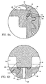
- stopper 84 includes a centrally disposed boss 122 depending downwardly from bottom surface 88.
- a venting channel or through hole 124 extends axially through boss 122 from upper orifice 123 to lower orifice 125.
- boss 122 is provided for additional structural support of channel 124.
- Stopper 84 further includes a groove 121 formed about orifice 123 of channel 124 for receiving a gasket 128. As will become clear in the discussion below, the gasket 128 serves to provide an air-tight seal of channel 124 during a centrifugation run.
- the width of channel 124 is constant along its length.
- Fig. 6B shows a preferred embodiment of the invention wherein the width of channel 124 increases with approach toward lower orifice 125.
- the result is a channel having an inverted funnel-shaped cross-section.
- the conical feature of the channel reduces the potential for droplets to hang, adhere or otherwise collect on the interior surface 124' of the channel.
- the reduction of droplets forming on surface 124' is critical in situations where a positive pressure has developed in receptacle 22. Such a pressure differential will force air to escape from the receptacle and will pull any droplets present on surface 124' up and out of channel 124 and deposit such droplets onto top surface 86.
- the conical channel 124 of Fig. 6B serves to minimize the occurrence of such droplets.
- Fig. 6C and 6D show an additional feature of the present invention, namely the incorporation of a filter (also known in the industry as a membrane) element 132 in the path of the channel.
- Figs. 6C and 6D show alternate placements of the filter element 132 in-line with the channel 124.
- the filter is a hydrophobic filter which can be mounted, press-fit, bonded, or otherwise fixed in position.
- the filter may be a replaceable component of stopper 84.
- Such filters are useful when there are concerns of aerosol contamination. These aerosols may be generated during the centrifugation run, on the lab bench, during which time the filter would prevent their escape from the receptacle and protect the user.
- the depending portion 92 of the stopper 84 is placed into the mouth 82 of the receptacle 22, and the lid 34 is threaded onto the neck portion 76, with the receptacle fitted into the canister 20 so that the frusto-conical surface 50 is seated against the cylindrical wall 26.
- the relative dimensions of the stopper 84 and the receptacle 22 are such that the depending portion 92 fits within the mouth 82. In this fashion, the gasket 98 is wedged against the neck portion 76, and the annular flange 94 approaches the upper edge 100 of the neck portion 76.
- the neck portion 76 includes an arcuate seating 102.
- the arcuate seating 102 is formed into the neck portion 76 to extend from the upper edge 100, away from the plurality of threads 80.
- the shape of the seating 102 produces a rolling action, when the gasket 98 is compressed. The rolling action reduces the amount of force necessitated to distort and squeeze the gasket 98 into the appropriate shape to form a fluid-tight and air-tight seal between the stopper 84 and the receptacle 22.
- the annular contact ring 68 of the lid 34 is positioned to seat against the annular flange 94 of the stopper 84, directly above the gasket 98.
- the annular contact ring 68 is sized so as to extend toward the stopper 84 a further distance than the second set of ribs 70. In this fashion, the second set of ribs 70 are spaced apart from the first major surface 86, forming a void 106 therebetween.
- central contact area 72 of lid 34 is in alignment with venting channel 124 of stopper 84. Furthermore in accordance with the invention, central boss 72 is coextensive with gasket 128. Thus as the lid is threaded onto receptacle 22 and stopper 84 is thereby received within the lid, central contact area of central boss 72 presses against gasket 128 thus creating an airtight seal of upper orifice 123 of channel 124. At the same time annular contact ring 68 of lid 34 presses against annular flange 94 of stopper 84 to reliably seal receptacle 22 as discussed above.
- the centrifuge container 10 As the rotor 12 rotates about its spin axis 16, the centrifuge container 10 is subjected to a centrifugal load, operating thereon in a direction parallel to the axis 18.
- the frusto-conical surface 50 allows the lid 34 and receptacle 22 to move toward the closed end 28 in response to the load, further tightening the seal between the gasket 54 and the cylindrical wall 26.
- the tubular portion 74 is in slidable engagement with the cylindrical wall 26, and the nadir 78 is spaced-apart from the closed end 28, when placed in the final seating position and the rotor 12 is at rest.
- the fluid-tight and air-tight seal formed between the gasket 54 and the cylindrical wall 26 prevents leakage of a sample or air from the canister 20, were the receptacle 22 to rupture or otherwise allow the sample to egress therefrom.
- a further advantage provided by the lid 34 is that the ribs 64 and 70, disposed thereon, amplify the force in response to centrifugal loading. Specifically, the ribs 64 and 70 are adapted to flex under centrifugal load, causing the apexes 66 and 72 to move toward the first major surface 86. The movement of the apexes 66 and 72 expands the circumference of the upper portion 44 of the peripheral member 38.
- Figs. 9 and 10 demonstrate the expansion of the circumference of the upper portion 44 of the peripheral member 38.
- the static dimensions of the lid 34 are shown in Fig. 9, when the rotor (not shown) is at rest, with the diameter of the peripheral member 38 being shown as D and the height of the apex 66 above the annular rim 46 shown as H.
- the height of the apex 66 above the annular rim 46 changes as a result of the centrifugal load, discussed above, so as to measure a distance h, with h ⁇ H.
- the aforementioned change in height results from the deflection of ribs 64 and 70.
- the deflection is in the range of 0.025 to 0.11 mm (0.0010 to .0045 inch), depending upon the rotational speed of the rotor and the rotor's size.
- the aforementioned deflection causes a proportional change in the diameter of the peripheral member.
- the diameter of the peripheral member 38 measures a distance d, with d > D. This results in an increase in the sealing force applied by the lid 34 that is proportional to the centrifugal load to which the lid 34 is subjected.
- the first and second sets of ribs 64 and 70 provide a sufficient amount of resistance to the centrifugal load to maintain the void 106 between the second set of ribs 70 and the first major side 86.
- This focuses the compressive force applied by the lid 34 onto the area of the stopper 84 which coincides with the annular contact ring 68. That is, the compressive force of lid 34 provided by the flexure of ribs 64 and 70 is transferred to annular flange 94 of the stopper via the annular contact ring, thus ensuring a reliable seal by the stopper. Focusing the compressive force of the lid 34 to the annular flange avoids decompression of gasket 98.
- the receptacle 22 includes a first alignment mark 108
- the lid 34 includes a second alignment mark 110.
- Both the first and second alignment marks 108 and 110 are arranged so as to be axially aligned after a predetermined amount of rotational movement between the lid 34 and the receptacle 22.
- the alignment marks 108 and 110 may be indicia, in the preferred embodiment, the first alignment mark 108 consists of a recess formed into the tubular wall 74 so as to extend along a length thereof.
- the recess functions as a vent to allow fluid to move freely as the receptacle is being placed in, or removed from, the canister 20. This prevents a vacuum, or positive pressure, from being present between the canister 20 and the receptacle 22, thereby facilitating coupling and decopuling of the same.
- the second alignment mark 110 is typically a detent.
- the lid 34 may include curved handle 112, the opposed ends of which are attached to one of the ribs 64 on opposing sides of the apex 66.
- the opposed ends may include circular loops 114 having a gap 116 present therein.
- One of the ribs 64 may include through-ways 118 in which one of the circular loops 114 is disposed. This allows the handle 112 to be rotatably attached to the lid 34, which facilitates placing the handle adjacent to the ribs 64 when not in use, shown in Fig. 11.
- a slot 120 may be formed into each rib 64 so as to receive the handle when placed adjacent thereto.
- the slots 120 may be of sufficient depth to allow the handle 112 to be disposed between the apex 66 and the annular ring 46.
- the flexibility of the ribs 64 and 70 shown more clearly in Figs. 3 and 5, may be augmented by increasing either the number or the size of the slots 120, present therein.
Landscapes
- Engineering & Computer Science (AREA)
- Mechanical Engineering (AREA)
- Health & Medical Sciences (AREA)
- Chemical & Material Sciences (AREA)
- Analytical Chemistry (AREA)
- General Health & Medical Sciences (AREA)
- Hematology (AREA)
- Clinical Laboratory Science (AREA)
- Chemical Kinetics & Catalysis (AREA)
- Centrifugal Separators (AREA)
- Closures For Containers (AREA)
- Measurement Of The Respiration, Hearing Ability, Form, And Blood Characteristics Of Living Organisms (AREA)
Description
- The present invention pertains to the field of centrifugation. Specifically, the present invention pertains to an improved capping assembly for removable sample-holding containers employed in centrifuges.
- Centrifuges are commonly used in medical and biological industries for separating and purifying materials of differing densities, such as viruses, bacteria, cells and proteins. A centrifuge includes a rotor and a container to support a sample undergoing centrifugation. The rotor is designed to hold the sample container while it spins up to tens of thousands of revolutions per minute. To avoid spillage, evaporation, or aerosoling of the sample, a cover is placed onto the container so as to provide a fluid-tight seal therebetween.
- During centrifugation, hydrostatic pressure within the container can compromise the seal integrity of the covered container. The hydrostatic pressure may force the sample to pass between the cover and the receptacle. Avoiding this type of leakage poses a great challenge when designing centrifuge sample containers. The prior art is replete with differing designs for sample-holding containers from which inspiration may be drawn to provide improved sample-holding centrifuge containers.
- U.S. Pat. No. 718,643 to Lees et al. discloses a sealing-jar for preserving articles of food, Fig. 1, including a body of a receptacle (a), a recess (b), a cover (c), a flat flange (d), a circular down-turned rib (e), and a rubber gasket (f). A seal is achieved by the gasket (f) fitting around the cover (c), beneath the flange (d), so as to bear against the recess (b), but this seal is easily compromised by centrifugal forces.
- Australian Pat. No. 4247/26 to Lucke et al. discloses an apparatus for sealing bottles and jars, Figs. 1-3, containing a domed disc stopper 8 having a downwardly projecting wall 9 near its outer edge. The wall 9 is inclined to match the seating 7 at the top of a rigid neck 5 of a jar or bottle. A
rigid cap 12 has internal screw-threads 6 that are designed to thread onto the neck 5. Aresilient ring 10 fits into an annular groove in the face of the stopper, col. 3 lines 4-8. Theresilient ring 10 seats against the neck 5 by thecap 12 pressing against the stopper 8. - U.S. Pat. No. 3,924,772 to Magnani et al. discloses an airtight container cap, Figs. 1-3, containing a ring-
nut 1 have an upper circular hole 2, a slot 3 on the side surface thereof and threads 4; a jar 7 with a threaded neck 6; glass stopper 8 having one groove 9 in the upper portion asecond groove 10 in the lower portion and ashoulder 12; and acircular gasket 11. Thecircular gasket 11 is positioned withingroove 10 of the glass stopper 8. The glass stopper 8 is then mounted inside of ring-nut 1 through hole 2. Ring-nut 1 is then threaded onto the neck 6 of a jar 7, forming a hermetic seal. - U.S. Pat. No. 4,844,273 to Hawkins et al. discloses a closure with enhanced sealing for a container, Figs. 1-3, comprising a
container neck lip 30 and acap 18 having aninner skirt 24, atop 20 and a depending coaxialouter skirt 22. The outer skirt hasinternal threads 26 for engaging the complementaryexternal threads 28 of the container neck. Theinner skirt 24 has an interference fit with the inside of thecontainer neck lip 30, thus, forming one element of the enhanced seal. Abead 32 projects inwardly from the dependingskirt 22 and provides the second element of the enhanced seal by maintaining peripheral contact against the outside of thecontainer neck lip 30. An o-ring 34 is positioned between the outer and inner skirts, 22 and 24, respectively, and becomes compressed between thetop 20 and thecontainer lip 30 to maintain a hermetic seal while thecap 18 is threaded on thecontainer neck 12. The rigid inner skirt firmly presses against the inside oflip 30 and co-acts with the inwardly directedbead 32 maintaining peripheral contact with theoutside lip 30, which helps to maintain the hermetic seal by retaining the o-ring 34 in its compressed state. - U.S. Pat. No. 5,291,783 to Hall discloses a
tube 10 for use in a fixed angle centrifugerotor having indicia 20 thereon indicating the level to which the tube may be filled with liquid without risk of spillage due to meniscus re-orientating. - U.S. Pat. No. 5,325,977 to Haynes et al. discloses a vented closure for a
capillary tube assembly 10. Theassembly 10 includes acapillary tube 12 having a bore extending therethrough and acap 14 slidably mounted to on end of thetube 12. Thecap 14 includes an enlargedhead 16 and a substantiallycylindrical body 18. One ormore vent grooves 20 are formed into the body which allows air to escape when thecap 14 is in a first slidable position. Thegroove 20 typically extends parallel to the longitudinal axis of thecylindrical body 18. - U.S. Pat. No. 5,458,252 discloses an invertible pressure-
responsive sealing cap 1 for attachment to a container 2 having a mouth 4 with an outwardly facing threadedportion 12. The mouth 4 has an inner cylindrical sealing surface 6. Thecap 1 has a threaded portion 3 disposed on a cap skirt 5, with the threaded portion 3 facing inwardly toward a cap axis 7. A central dome portion 9 is symmetrically disposed about the cap axis 7 and extends outwardly therefrom, terminating in anannular portion 11. The dome portion 9 is initially concave and extends into the mouth 4 of the container 2. The interface of the dome portion 9 and theannular portion 11 define afirst flexure area 17. A sealing portion 13 is disposed about theannular portion 11, defining a second flexure area 21 thereat. The sealing portion 13 includes an outwardly facingcylindrical surface 23. In operation, thecap 1 is mated to the container 2 and pressure build-up therein causes the dome portion 9 to flatten, increasing the sealing force between thesealing surfaces 23 and 6. A drawback with the aforementioned containers is that the fluid-tight integrity of the seals is compromised by samples egressing therethrough during centrifugation, which has led to the development of seals which employ centrifugal force to drive a cap or plug against a container. - U.S. Pat Nos. 5,127,895 to R. Pawlovich; 5,395, 001 to P. Moore; 5,361,922 to P. Moore et al.; 4,304,356 to S. Chulay et al.; 4,290,550 to S. Chulay et al.; 4,080,175 to S. Chulay et al.; and 4,076,170 to S. Chulay et al. al., all assigned to the assignee of the present invention, disclose centrifuge containers which achieve a seal by having a cap or plug forced against a container under centrifugal force. In some of these patents, deformable o-rings are used as part of the seal mechanism. Tapered surfaces, annular ridges and annular grooves are all employed, as in U.S. Pat. No. 5,395,001, to achieve a sealed sample.
- For centrifuge containers having large diameter openings, structural flexure of the sample containment assembly during a centrifugation run may permit air to pass from within the container. Thus, a container having a lid for sealing its open end will be subject to a small but significant negative air pressure as a result of the venting of air from the container. This presents operational difficulties to the lab technician who must contend with carefully removing the vacuum sealed lid without doing damage to it, and yet desires to rapidly perform the operation in order to minimize the down time between centrifugation runs.
- What is needed is a capping assembly for a centrifuge container that is capable of maintaining a tight seal during a centrifugation run while at the same time is capable of easily releasing a vacuum that may develop within the container during the run. It is desirable that such a capping assembly be manufactured with minimum parts and easily maintained during its useful life.
- GB1174337 discloses an applicator for fluids or pastes stored in the hollow interior of the applicator body whose upper end is closed by a web or stopper having a central hole through which the fluid or paste is dispensed. The central hole holds a valve member that is normally held outwardly away from the web or stopper by radially extending resilient feet so as to open the central hole to the passage of the fluids or pastes. The web or stopper and its valve member are covered by a thick resilient two-layer porous cover through which the fluid or paste is dispensed when the applicator is uncapped. When the applicator is closed by its cap, a central boss on the inside of the lid presses down on the outside of the resilient cover, and the inside of this resilient porous cover in turn tends to push the valve member down against the web or stopper around the central hole to close the hole to the passage of fluid or paste.
- According to the present invention there is provided a cap assembly for a centrifuge container, said cap assembly comprising a stopper member adapted to seal an open end of said container, said stopper member having opposed top and bottom surfaces, a closeable channel extending through the centre of said stopper member between said stopper member top and bottom surfaces, said channel having an upper orifice opening through said stopper member top surface and a lower orifice opening through said stopper member bottom surface; and a lid member adapted to removably contact said stopper member when said stopper member is received in said open end of said container, said lid member having opposed top and bottom surfaces, said lid member bottom surface having downwardly depending ribs mutually converging into a downwardly depending central boss providing a central contact area that contacts said stopper member top surface around said upper orifice opening to close said channel when said stopper member is received in said open end of said container and said lid member is engaged with the stoppered end of said container to cause the central contact area of said central boss to contact and press down upon said stopper member top surface around said upper orifice opening, removal of said lid member from the stoppered end of said container raising the central contact area of said central boss from said stopper member top surface around said upper orifice opening to open said channel.
- Fig. 1 is an exploded perspective view of the capping assembly employed in a dual-vessel removable sample-holding centrifuge container, in accord with the present invention.
- Fig. 2 is a perspective view showing a dual-vessel removable sample-holding centrifuge container of Fig. 1 placed in a centrifuge rotor in accord with the present invention.
- Fig. 3 is a top down view of a lid shown in Fig 1.
- Figs. 4A and 4B are cross-sectional views of the lid shown in Fig. 3 taken along view lines A-A and B-B respectively.
- Fig. 5 is a bottom view of the lid shown in Fig 3.
- Figs. 6A-6D are cross-sectional views of various embodiments of a stopper or plug shown in Fig.1.
- Fig. 7 is a cross-sectional view of the container shown in Fig. 1, with the capping assembly shown in a final seating position.
- Figs. 8A and 8B are detailed views of the container shown in Fig.7.
- Fig. 9 is a side view of the lid shown in Fig 3 when at rest.
- Fig. 10 is the lid shown in Fig. 9 when subjected to centrifugal loading.
- Fig. 11 is a top down view of the lid shown in Fig. 3, having a handle disposed thereon.
- Fig. 12 is perspective view of the handle shown in Fig. 11.
- With reference to both Figs. 1 and 2, a dual
vessel centrifuge container 10 is shown for use in a fixed-angle centrifuge rotor 12 of the type having a plurality ofbores 14 disposed radially symmetric about therotor 12'sspin axis 16. In fixedangle centrifuge rotor 12, alengthwise axis 18 of the centrifuge container forms an angle Θ, with respect to thespin axis 16. Thecentrifuge container 10 includes acanister 20, areceptacle 22 and a cappingassembly 24. Thecanister 20 may be permanently fixed to therotor 12 or be removably attached thereto and have any cross-sectional area desired. For clarity, thecanister 20 will be discussed as being removably attached to therotor 12 and having a circular cross-sectional area defined by acylindrical wall 26 that extends from aclosed end 28, terminating in anopen end 30. Protruding from thecylindrical wall 26, between theclosed end 28 and theopen end 30, is anannular shoulder 32. Each of thebores 14 is shaped to receive thecanister 20 so that theshoulder 32 rests against therotor 12. - Referring to Figs. 1, 3, 4A, 4B and 5, the capping
assembly 24 includes alid 34 having acover portion 36 and aperipheral member 38, surrounding thecover portion 36 and extending transverse thereto. Thecover portion 36 has first and second opposedmajor sides first side 40 has a convex shape, and thesecond side 42 has a concave shape. Anupper portion 44 of theperipheral member 38 extends away from thesecond side 42, terminating in anannular rim 46 positioned to face the firstmajor side 40. Theupper portion 44 includes aninner surface 48 and anouter surface 50, disposed opposite to theinner surface 48. Theinner surface 48 extends between an upper surface of theannular rim 46 and thefirst side 40. Theouter surface 50 extends from theannular rim 46 toward the secondmajor side 42, terminating at an area of theperipheral member 38 that is positioned opposite to thecover portion 36. Theouter surface 50 has a frusto-conical shape and includes anannular recess 52 to receive a gasket, e.g. o-ring 45. Theannular rim 46 projects outwardly beyond theouter surface 50 and may be roughened or knurled to facilitate gripping the same. Alower portion 54 of theperipheral member 38 extends away from theupper portion 44, terminating in anannulus 56 which faces the secondmajor side 42. Thelower portion 54 includes inside and outside surfaces, 58 and 60, respectively. Theinside surface 58 extends between thesecond side 42 and theannulus 56. Theoutside surface 60 is contiguous with theouter surface 50, extending between theannular recess 52 and theannulus 56. Thelower portion 54 includes a plurality ofthreads 62 that are present on theinside surface 58. It is preferred, however, that the plurality ofthreads 62 be disposed on theinside surface 58. - Referring to Figs. 3 and 5, a first set of
arcuate ribs 64 extends across thefirst side 40, following the contour thereof. Each of theribs 64 traverses the extent of thecover portion 36 between opposed areas of theinner surface 48. Theribs 64 of the first set intersect proximate to a center of thecover portion 36, forming an apex 66 thereat. Anannular contact ring 68 is disposed on the secondmajor side 42 so as to be proximate to theinside surface 58 of thelower portion 54. A second set ofribs 70 extends across thesecond side 42, between opposed areas of theannular contact ring 68. The second set ofribs 70 are arcuate in that they follow the contour of thesecond side 42 and inter-sect proximate to acentral boss 72 of thecover portion 36. Each of theribs peripheral member 38 outwardly, discussed more fully below. - The surfaces of
annular contact ring 68 andcentral contact area 72 are substantially coplanar. This is shown in the cross-sectional view of Fig. 4B. This aspect of the invention will be discussed more fully below. - Referring to Figs. 1, 4A and 4B, the
receptacle 22 may be formed of any polymeric material which can be molded to include atubular portion 74 extending from a threadedneck portion 76, terminating in aclosed nadir 78. The inside diameter of thetubular portion 74 varies along the length thereof, providing the inside surface of thetubular portion 74 with a gradual taper. Specifically, the inside diameter of thetubular portion 74 is smallest proximate to theneck portion 76 and gradually increases so as to be largest proximate to thenadir 78. This eases the removal of a sample therefrom by facilitating access thereto by a spatula (not shown) or other device. Compared to the remaining portions of thereceptacle 22, theneck portion 76 is provided with increased wall thickness, and therefore, increased strength, due to the gradual taper of the inside surface. Theneck portion 76 includes a plurality ofthreads 80 and defines anopen mouth 82. The plurality ofthreads 62 disposed on theinside surface 58 of thelower portion 54 are adapted to engage the plurality ofthreads 80 of theneck portion 76. In this fashion, thelid 34 threadably engages thereceptacle 22, with the secondmajor side 42 being positioned adjacent to theneck portion 76 when placed in the final seating position. To obtain fluid-tight and air-tight integrity between thelid 34 and thereceptacle 22, a sealing device is disposed between thesecond side 42 and theneck portion 76. In accordance with the present invention, a stopper or plugmember 84 serves as such a sealing device. - Referring to Figs 1 and 6A-6D, the
stopper 84 has a first major surface 86 (top surface) and a second major surface 88 (bottom surface) disposed opposite to the firstmajor surface 86, as well as aperipheral surface 90 extending therebetween. Anannular depending portion 92 extends from the secondmajor surface 88, away from said firstmajor surface 86. The dependingportion 92 extends from an area of the secondmajor surface 88 which is spaced-apart from theperipheral surface 90, defining anannular flange 94. Anannular shoulder 96 is provided, between theannular flange 94 and the dependingportion 92, to receive agasket 98, such as an o-ring. To ensure that thegasket 98 is retained on thestopper 84, apositive surface feature 99, such as a circumferential ridge, is provided on the dependingportion 92. - In accordance with the present invention,
stopper 84 includes a centrallydisposed boss 122 depending downwardly frombottom surface 88. A venting channel or throughhole 124 extends axially throughboss 122 fromupper orifice 123 tolower orifice 125. Although not needed,boss 122 is provided for additional structural support ofchannel 124.Stopper 84 further includes agroove 121 formed aboutorifice 123 ofchannel 124 for receiving agasket 128. As will become clear in the discussion below, thegasket 128 serves to provide an air-tight seal ofchannel 124 during a centrifugation run. - As can be seen in Fig. 6A, the width of
channel 124 is constant along its length. Fig. 6B, however, shows a preferred embodiment of the invention wherein the width ofchannel 124 increases with approach towardlower orifice 125. The result is a channel having an inverted funnel-shaped cross-section. The conical feature of the channel reduces the potential for droplets to hang, adhere or otherwise collect on the interior surface 124' of the channel. The reduction of droplets forming on surface 124' is critical in situations where a positive pressure has developed inreceptacle 22. Such a pressure differential will force air to escape from the receptacle and will pull any droplets present on surface 124' up and out ofchannel 124 and deposit such droplets ontotop surface 86. Theconical channel 124 of Fig. 6B serves to minimize the occurrence of such droplets. - Fig. 6C and 6D show an additional feature of the present invention, namely the incorporation of a filter (also known in the industry as a membrane)
element 132 in the path of the channel. Figs. 6C and 6D show alternate placements of thefilter element 132 in-line with thechannel 124. Typically, the filter is a hydrophobic filter which can be mounted, press-fit, bonded, or otherwise fixed in position. Alternatively, the filter may be a replaceable component ofstopper 84. Such filters are useful when there are concerns of aerosol contamination. These aerosols may be generated during the centrifugation run, on the lab bench, during which time the filter would prevent their escape from the receptacle and protect the user. - Referring to Figs, 1,2, 6A-6D, 7, 8A and 8B in operation, the depending
portion 92 of thestopper 84 is placed into themouth 82 of thereceptacle 22, and thelid 34 is threaded onto theneck portion 76, with the receptacle fitted into thecanister 20 so that the frusto-conical surface 50 is seated against thecylindrical wall 26. To that end, the relative dimensions of thestopper 84 and thereceptacle 22 are such that the dependingportion 92 fits within themouth 82. In this fashion, thegasket 98 is wedged against theneck portion 76, and theannular flange 94 approaches theupper edge 100 of theneck portion 76. To allow thegasket 98 to conform with the shape of theshoulder 96, while reducing the force necessitated to achieve the same, theneck portion 76 includes anarcuate seating 102. Thearcuate seating 102 is formed into theneck portion 76 to extend from theupper edge 100, away from the plurality ofthreads 80. The shape of theseating 102 produces a rolling action, when thegasket 98 is compressed. The rolling action reduces the amount of force necessitated to distort and squeeze thegasket 98 into the appropriate shape to form a fluid-tight and air-tight seal between thestopper 84 and thereceptacle 22. To facilitate the aforementioned compression, theannular contact ring 68 of thelid 34 is positioned to seat against theannular flange 94 of thestopper 84, directly above thegasket 98. Theannular contact ring 68 is sized so as to extend toward the stopper 84 a further distance than the second set ofribs 70. In this fashion, the second set ofribs 70 are spaced apart from the firstmajor surface 86, forming a void 106 therebetween. - By virtue of its axial alignment,
central contact area 72 oflid 34 is in alignment with ventingchannel 124 ofstopper 84. Furthermore in accordance with the invention,central boss 72 is coextensive withgasket 128. Thus as the lid is threaded ontoreceptacle 22 andstopper 84 is thereby received within the lid, central contact area ofcentral boss 72 presses againstgasket 128 thus creating an airtight seal ofupper orifice 123 ofchannel 124. At the same timeannular contact ring 68 oflid 34 presses againstannular flange 94 ofstopper 84 to reliably sealreceptacle 22 as discussed above. - As the
rotor 12 rotates about itsspin axis 16, thecentrifuge container 10 is subjected to a centrifugal load, operating thereon in a direction parallel to theaxis 18. The frusto-conical surface 50 allows thelid 34 andreceptacle 22 to move toward theclosed end 28 in response to the load, further tightening the seal between thegasket 54 and thecylindrical wall 26. To facilitate this movement, thetubular portion 74 is in slidable engagement with thecylindrical wall 26, and thenadir 78 is spaced-apart from theclosed end 28, when placed in the final seating position and therotor 12 is at rest. The fluid-tight and air-tight seal formed between thegasket 54 and thecylindrical wall 26 prevents leakage of a sample or air from thecanister 20, were thereceptacle 22 to rupture or otherwise allow the sample to egress therefrom. A further advantage provided by thelid 34 is that theribs ribs apexes major surface 86. The movement of theapexes upper portion 44 of theperipheral member 38. - Figs. 9 and 10 demonstrate the expansion of the circumference of the
upper portion 44 of theperipheral member 38. The static dimensions of thelid 34 are shown in Fig. 9, when the rotor (not shown) is at rest, with the diameter of theperipheral member 38 being shown as D and the height of the apex 66 above theannular rim 46 shown as H. As shown in Fig. 10, during centrifugation, the height of the apex 66 above theannular rim 46 changes as a result of the centrifugal load, discussed above, so as to measure a distance h, with h < H. The aforementioned change in height results from the deflection ofribs peripheral member 38 measures a distance d, with d > D. This results in an increase in the sealing force applied by thelid 34 that is proportional to the centrifugal load to which thelid 34 is subjected. - Referring again to Figs. 2, 6A, 7 and 8, the first and second sets of
ribs ribs 70 and the firstmajor side 86. This focuses the compressive force applied by thelid 34 onto the area of thestopper 84 which coincides with theannular contact ring 68. That is, the compressive force oflid 34 provided by the flexure ofribs annular flange 94 of the stopper via the annular contact ring, thus ensuring a reliable seal by the stopper. Focusing the compressive force of thelid 34 to the annular flange avoids decompression ofgasket 98. - The flexing of
ribs central boss 72 oflid 34 maintains an airtight seal ofchannel orifice 123. During centrifugation, the central region ofstopper 84 will tend to flex downward due to loading by centrifugal forces. This tends to bringgasket 128 away from the central contact area oflid 34, which would break the seal. However, because of the flexure ofribs central boss 72 will also deform in the direction ofstopper 84, maintaining contact withgasket 128 and thus ensure an airtight seal during centrifugation. - At the end of a centrifugation run, it has been noted above that occasionally the
receptacle 22 develops a vacuum which could make difficult the removal of thestopper 84. However, in the present invention, such difficulty is overcome simply by the act of removing thelid 34 from the receptacle. As thelid 34 is unscrewed, the central contact area ofcentral boss 72 lifts away fromgasket 128 of the stopper, allowing air to pass throughchannel 124 thereby relieving the vacuum withinreceptacle 22. The stopper is now effortlessly removed as a result of the equalization of pressure between the interior ofreceptacle 22 and the surrounding environment. - Referring to Figs. 1 and 8A, to achieve a fluid-tight and air-tight seal between the
gasket 98 and theseating 102, thereceptacle 22 includes afirst alignment mark 108, and thelid 34 includes asecond alignment mark 110. Both the first and second alignment marks 108 and 110 are arranged so as to be axially aligned after a predetermined amount of rotational movement between thelid 34 and thereceptacle 22. Although the alignment marks 108 and 110 may be indicia, in the preferred embodiment, thefirst alignment mark 108 consists of a recess formed into thetubular wall 74 so as to extend along a length thereof. In this design, the recess functions as a vent to allow fluid to move freely as the receptacle is being placed in, or removed from, thecanister 20. This prevents a vacuum, or positive pressure, from being present between thecanister 20 and thereceptacle 22, thereby facilitating coupling and decopuling of the same. Thesecond alignment mark 110 is typically a detent. - Referring to Figs. 1, 4A, 11 and 12, additional features may be provided to facilitate coupling and decoupling of the various components of the dual
vessel centrifuge container 10. For example, thelid 34 may includecurved handle 112, the opposed ends of which are attached to one of theribs 64 on opposing sides of the apex 66. The opposed ends may includecircular loops 114 having agap 116 present therein. One of theribs 64 may include through-ways 118 in which one of thecircular loops 114 is disposed. This allows thehandle 112 to be rotatably attached to thelid 34, which facilitates placing the handle adjacent to theribs 64 when not in use, shown in Fig. 11. To further reduce the drag that thehandle 112 may create during centrifugation, aslot 120 may be formed into eachrib 64 so as to receive the handle when placed adjacent thereto. Theslots 120 may be of sufficient depth to allow thehandle 112 to be disposed between the apex 66 and theannular ring 46. In addition, the flexibility of theribs slots 120, present therein.
Claims (13)
- A cap assembly (24) for a centrifuge container (22), said cap assembly (24) comprising:characterised in that said lid member bottom surface (42) has downwardly depending ribs (70) mutually converging into a downwardly depending central boss (72) providing a central contact area that contacts said stopper member top surface (86) around said upper orifice opening (123) to close said channel (124) when said stopper member (84) is received in said open end (82) of said container (22) and said lid member (34) is engaged with the stoppered end (82) of said container (22) to cause the central contact area of said central boss (72) to contact and press down upon said stopper member top surface (86) around said upper orifice opening (123), removal of said lid member (34) from the stoppered end (82) of said container (22) raising the central contact area of said central boss (72) from said stopper member top surface (86) around said upper orifice opening (123) to open said channel (124).a stopper member (84) adapted to seal an open end (82) of said container (22), said stopper member (84) having opposed top and bottom surfaces (86, 88), a closeable channel (124) extending through the centre of said stopper member (84) between said stopper member top and bottom surfaces (86, 88), said channel (124) having an upper orifice opening (123) through said stopper member top surface (86) and a lower orifice opening (125) through said stopper member bottom surface (88); anda lid member (34) adapted to removably contact said stopper member (84) when said stopper member (84) is received in said open end (82) of said container (22), said lid member (34) having opposed top and bottom surfaces (40, 42),
- A cap assembly (24) as claimed in claim 1 wherein said upper orifice (123) is flush with said stopper member top surface (86).
- A cap assembly (24) as claimed in claim 1 wherein said channel (124) has a varying width therealong.
- A cap assembly (24) as claimed in claim 1 wherein said channel (124) has a gradually widening opening (124') with approach to said stopper member bottom surface (88).
- A cap assembly (24) as claimed in claim 1 wherein said channel (124) includes a filter element (132) along its path.
- A cap assembly (24) as claimed in claim 1 wherein the stopper member bottom surface (88) includes a boss (122) disposed about said central axis, said channel (124) passing through said boss (122).
- A cap assembly (24) as claimed in claim 6 further including a gasket member (128) disposed about said upper orifice opening (123).
- A cap assembly (24) as claimed in any one of claims 1 to 7 wherein said stopper member (84) comprises a flanged rim (90), said flanged rim (90) including a rim portion (92) to be received in said open end (82) and a flange portion (94) to rest upon a portion of an upper surface (100) of said open end (82).
- A cap assembly (24) as claimed in claim 7 wherein the downwardly depending central boss (72) is coextensive with said gasket member (128) and aligned for engagement therewith, thereby providing a fluid-tight seal to prevent fluid flow through said upper orifice opening (123) when said lid member (34) is engaged with the stoppered end (82) of said container (22).
- A cap assembly (24) as claimed in claim 8 wherein said stopper member (84) further includes a fluid-tight sealing element (98) circumferentially disposed about said rim portion (92) and on the underside of said flange portion (94), said rim portion (92) having a positive surface feature (99)for retaining said fluid-tight sealing (98) in position.
- A cap assembly (24) as claimed in any one of claims 1 to 10, wherein the lid member (34) is threaded to receive a correspondingly threaded open end of said container (22) and said stopper member (84) is adapted to be received within said threaded lid member (34).
- A cap assembly (24) as claimed in claim 11 as directly or indirectly dependent on claim 7 wherein said stopper member (84) further includes a groove (121) disposed about a circumference of said vented channel with said gasket member (128) seated therein.
- A cap assembly (24) as claimed in claim 4 wherein said channel (124) has a funnel-shaped cross-section, the wide end of said funnel shape opening at said bottom surface (88) of said stopper member (84).
Applications Claiming Priority (2)
| Application Number | Priority Date | Filing Date | Title |
|---|---|---|---|
| US942973 | 1997-10-02 | ||
| US08/942,973 US5899349A (en) | 1997-10-02 | 1997-10-02 | Cap/closure having a venting mechanism for use with centrifuge containers |
Publications (3)
| Publication Number | Publication Date |
|---|---|
| EP0906869A2 EP0906869A2 (en) | 1999-04-07 |
| EP0906869A3 EP0906869A3 (en) | 1999-04-14 |
| EP0906869B1 true EP0906869B1 (en) | 2003-02-26 |
Family
ID=25478903
Family Applications (1)
| Application Number | Title | Priority Date | Filing Date |
|---|---|---|---|
| EP98307210A Expired - Lifetime EP0906869B1 (en) | 1997-10-02 | 1998-09-07 | Cap/closure having a venting mechanism for use with centrifuge containers |
Country Status (4)
| Country | Link |
|---|---|
| US (1) | US5899349A (en) |
| EP (1) | EP0906869B1 (en) |
| JP (1) | JP4395207B2 (en) |
| DE (1) | DE69811590T2 (en) |
Families Citing this family (34)
| Publication number | Priority date | Publication date | Assignee | Title |
|---|---|---|---|---|
| US8904886B1 (en) * | 1996-08-22 | 2014-12-09 | A+ Manufacturing LLC | Devices for obtaining cylinder samples of natural gas or process gas and methods therefore |
| US6062407A (en) * | 1997-04-25 | 2000-05-16 | Beckman Coulter, Inc. | Centrifugally loaded self-sealing integral one-piece cap/closure |
| US6041982A (en) * | 1999-02-10 | 2000-03-28 | Dart Industries Inc. | Beverage container with cap and spout |
| US6866826B2 (en) * | 2000-12-30 | 2005-03-15 | Beckman Coulter, Inc. | Large mouth centrifuge labware |
| US6699168B2 (en) * | 2001-12-20 | 2004-03-02 | Beckman Coulter, Inc. | Rotary centrifuge having pivoting buckets for holding samples |
| US6783020B2 (en) * | 2002-11-15 | 2004-08-31 | Gerber Products Company | Toddler drinking cup |
| USD507934S1 (en) | 2002-11-15 | 2005-08-02 | Gerber Products Company | Cup |
| US20040179971A1 (en) * | 2003-03-12 | 2004-09-16 | Becton, Dickinson And Company | Method and device for transporting evacuated blood collection tubes |
| DE10342091A1 (en) * | 2003-09-10 | 2005-04-28 | Heraeus Kulzer Gmbh | Cartridge with ventable piston |
| US6899254B1 (en) | 2004-01-20 | 2005-05-31 | Plas-Pak Industries, Inc. | Venting seal for dispenser |
| US8137329B2 (en) | 2004-03-25 | 2012-03-20 | Medindica-Pak, Inc. | Method and apparatus for transforming a delivery container into a waste disposal system |
| US8118795B2 (en) | 2005-03-22 | 2012-02-21 | Medindica-Pak, Inc | Disposal chain supply systems method and apparatus |
| US7854729B2 (en) * | 2006-04-17 | 2010-12-21 | Medindica-Pak, Inc. | Supply chain method and apparatus for sealing and unsealing a vacuum draw path |
| KR100767448B1 (en) * | 2006-06-30 | 2007-10-17 | 메디칸(주) | Centrifuge and Centrifugal Method |
| EP2144824B1 (en) * | 2007-04-13 | 2018-08-15 | Waters Technologies Corporation | Vessel and method for containing fluids |
| US8863594B2 (en) | 2008-02-22 | 2014-10-21 | Foxx Life Sciences | Sample container and filtration apparatus and method of filtration using same |
| US20090215150A1 (en) * | 2008-02-22 | 2009-08-27 | Jeffrey Kane | Sample container and filtration apparatus and method of filtration using the same |
| DE102008031502B4 (en) * | 2008-07-03 | 2010-05-12 | Thermo Electron Led Gmbh | centrifuge tube |
| EP2269740B1 (en) * | 2009-06-30 | 2015-11-04 | Hitachi Koki CO., LTD. | Centrifugal separator |
| US9211969B2 (en) * | 2010-02-22 | 2015-12-15 | Medline Industries, Inc | Specimen container |
| DE102010016866B4 (en) * | 2010-05-10 | 2018-06-21 | Helvoet Pharma Belgium N.V. | Closure for a container and method for carrying out a freeze-drying method |
| US8955557B2 (en) | 2010-05-12 | 2015-02-17 | Medindica-Pak, Inc. | Environmental NuChain enterprise resource planning method and apparatus |
| US8540689B2 (en) | 2010-05-14 | 2013-09-24 | Medindica-Pak, Inc | NuChain NuPurposing container conditioning method and apparatus |
| KR101226154B1 (en) * | 2010-10-25 | 2013-01-24 | 강도원 | Airtight container for laboratory |
| US9663275B2 (en) * | 2013-07-09 | 2017-05-30 | Owens-Brockway Glass Container Inc. | Vented overcap and lid |
| US9987634B2 (en) | 2014-12-03 | 2018-06-05 | Fiberlite Centrifuge, Llc | Centrifuge sample container and closure therefor |
| USD777342S1 (en) | 2014-12-03 | 2017-01-24 | Fiberlite Centrifuge, Llc | Centrifuge bottle handle |
| US10112199B2 (en) | 2014-12-03 | 2018-10-30 | Fiberlite Centrifuge, Llc | Centrifuge sample container and closure therefore |
| USD777941S1 (en) | 2015-07-17 | 2017-01-31 | Fiberlite Centrifuge, Llc | Centrifuge bottle |
| CN105689033B (en) * | 2016-03-05 | 2017-11-21 | 河南科技大学第一附属医院 | A kind of centrifuge tube |
| CN105728074B (en) * | 2016-03-05 | 2017-12-29 | 刘纪刚 | A kind of centrifuge tube |
| KR101894966B1 (en) * | 2017-03-30 | 2018-09-04 | 신현순 | A container for centrifugal separator |
| EP3898004B1 (en) * | 2018-12-19 | 2024-08-07 | Silgan Dispensing Systems Slatersville LLC | Measured dose dispensers |
| EP4108308B1 (en) * | 2020-02-19 | 2025-04-02 | AB MV Group Production | Sealing filtering device, stopper thereof, and assembly for closing a bottle containing a liquid |
Citations (2)
| Publication number | Priority date | Publication date | Assignee | Title |
|---|---|---|---|---|
| US3924772A (en) * | 1974-02-08 | 1975-12-09 | Fidenza Vetraria Spa | Airtight container cap |
| US4844273A (en) * | 1988-09-06 | 1989-07-04 | Sunbeam Plastics Corporation | Closure with enhanced sealing |
Family Cites Families (25)
| Publication number | Priority date | Publication date | Assignee | Title |
|---|---|---|---|---|
| US718643A (en) * | 1902-04-14 | 1903-01-20 | Charles C Hovey | Sealing-jar for preserving articles of food. |
| FR662110A (en) * | 1927-06-30 | 1929-08-02 | Eau De Cologne Fabriek J C Bol | Bottle closure |
| DE717393C (en) * | 1939-09-12 | 1942-02-13 | Wilhelm Fink | Bottle closure with a spray or drip opening |
| FR880076A (en) * | 1940-07-12 | 1943-03-12 | Cooking glass | |
| FR1159634A (en) * | 1956-07-12 | 1958-06-30 | Louis Besse Ets | Dropper cap for bottles and other containers |
| CH354683A (en) * | 1957-03-21 | 1961-05-31 | Weickel Philipp | Closure on bottles |
| US3247992A (en) * | 1962-01-26 | 1966-04-26 | Thatcher Glass Mfg Company Inc | Resealable bottle closure |
| GB943323A (en) * | 1962-03-23 | 1963-12-04 | Hakon Wiederquist | A closure means for containers |
| US3339772A (en) * | 1964-11-16 | 1967-09-05 | Formold Plastics Inc | Container cap |
| GB1174337A (en) * | 1967-06-06 | 1969-12-17 | Gilbert Schwartzman | Applicator with Cap-Closed Valve. |
| US4076170A (en) * | 1977-04-18 | 1978-02-28 | Beckman Instruments, Inc. | Tube cap assembly for preparative centrifuge rotors |
| US4080175A (en) * | 1977-04-19 | 1978-03-21 | Beckman Instruments, Inc. | Internally activated sealing centrifuge test tube cap assembly |
| US4290550A (en) | 1980-02-19 | 1981-09-22 | Beckman Instruments, Inc. | Modular supporting cap and spacer for centrifuge tubes |
| US4304356A (en) * | 1980-02-19 | 1981-12-08 | Beckman Instruments, Inc. | Supporting cap for sealed centrifuge tube |
| US5127895A (en) * | 1990-03-30 | 1992-07-07 | Beckman Instruments, Inc. | Self-seal centrifuge tube |
| GB9108694D0 (en) * | 1991-04-17 | 1991-06-12 | Jaycare Ltd | Improvements relating to tamper evident(te)closures |
| US5203825A (en) * | 1991-06-07 | 1993-04-20 | Becton, Dickinson And Company | Capillary tube assembly including a vented cap |
| US5291783A (en) * | 1992-12-21 | 1994-03-08 | E. I. Du Pont De Nemours And Company | Tube for use in a fixed angle centrifuge rotor |
| US5395001A (en) * | 1993-04-02 | 1995-03-07 | Beckman Instruments, Inc. | Supporting spacer for self-sealing centrifuge tubes |
| US5361922A (en) * | 1993-04-02 | 1994-11-08 | Beckman Instruments, Inc. | Centrifuge tubes with snap plugs |
| US5458252A (en) * | 1994-06-03 | 1995-10-17 | American Precision Plastics Corporation | Invertible, pressure-responsive sealing cap |
| WO1996006018A1 (en) * | 1994-08-19 | 1996-02-29 | W. L. Gore & Associates, Inc. | Vented vial for freeze-drying and method of minimizing contamination of freeze-dried products |
| US5499735A (en) * | 1994-12-20 | 1996-03-19 | Chen; Cin-Chen | Closure assembly for vacuum sealed containers |
| US5667755A (en) * | 1995-05-10 | 1997-09-16 | Beckman Instruments, Inc. | Hybrid composite centrifuge container with interweaving fiber windings |
| GB2312207B (en) * | 1996-10-25 | 1998-08-26 | Massmould Holdings | Plug closure assembly |
-
1997
- 1997-10-02 US US08/942,973 patent/US5899349A/en not_active Expired - Lifetime
-
1998
- 1998-09-07 EP EP98307210A patent/EP0906869B1/en not_active Expired - Lifetime
- 1998-09-07 DE DE69811590T patent/DE69811590T2/en not_active Expired - Lifetime
- 1998-09-16 JP JP26189098A patent/JP4395207B2/en not_active Expired - Lifetime
Patent Citations (2)
| Publication number | Priority date | Publication date | Assignee | Title |
|---|---|---|---|---|
| US3924772A (en) * | 1974-02-08 | 1975-12-09 | Fidenza Vetraria Spa | Airtight container cap |
| US4844273A (en) * | 1988-09-06 | 1989-07-04 | Sunbeam Plastics Corporation | Closure with enhanced sealing |
Also Published As
| Publication number | Publication date |
|---|---|
| DE69811590D1 (en) | 2003-04-03 |
| JPH11179238A (en) | 1999-07-06 |
| US5899349A (en) | 1999-05-04 |
| EP0906869A2 (en) | 1999-04-07 |
| DE69811590T2 (en) | 2003-12-04 |
| EP0906869A3 (en) | 1999-04-14 |
| JP4395207B2 (en) | 2010-01-06 |
Similar Documents
| Publication | Publication Date | Title |
|---|---|---|
| EP0906869B1 (en) | Cap/closure having a venting mechanism for use with centrifuge containers | |
| JP4913166B2 (en) | Cap and cap assembly for centrifuge container | |
| EP1021250B1 (en) | Centrifugally loaded self-sealing integral one-piece cap/closure | |
| US3849072A (en) | Plasma separator | |
| US5458854A (en) | Collection assembly | |
| EP0517121B1 (en) | Capillary tube assembly including a vented cap | |
| US7387216B1 (en) | Closure device for containers | |
| JP5199418B2 (en) | Collection assembly | |
| US6145688A (en) | Closure device for containers | |
| AU681486B2 (en) | Collection assembly | |
| CA1302370C (en) | Method and apparatus for dispensing liquids | |
| US4052320A (en) | Telescoping serum separator and dispenser | |
| US20030053938A1 (en) | Liquid specimen collection container | |
| US4687479A (en) | Blood storage device | |
| US4537320A (en) | Centrifuge tube having removable crown and swage fitting | |
| NZ335580A (en) | Universal plug for a container | |
| EP0116065A1 (en) | Dispensing bottle and method | |
| WO2024215675A1 (en) | Pressure-equalizing cap for sampling apparatus |
Legal Events
| Date | Code | Title | Description |
|---|---|---|---|
| PUAI | Public reference made under article 153(3) epc to a published international application that has entered the european phase |
Free format text: ORIGINAL CODE: 0009012 |
|
| PUAL | Search report despatched |
Free format text: ORIGINAL CODE: 0009013 |
|
| AK | Designated contracting states |
Kind code of ref document: A2 Designated state(s): DE FR GB |
|
| AX | Request for extension of the european patent |
Free format text: AL;LT;LV;MK;RO;SI |
|
| AK | Designated contracting states |
Kind code of ref document: A3 Designated state(s): AT BE CH CY DE DK ES FI FR GB GR IE IT LI LU MC NL PT SE |
|
| AX | Request for extension of the european patent |
Free format text: AL;LT;LV;MK;RO;SI |
|
| 17P | Request for examination filed |
Effective date: 19991002 |
|
| AKX | Designation fees paid |
Free format text: DE FR GB |
|
| 17Q | First examination report despatched |
Effective date: 20010718 |
|
| GRAG | Despatch of communication of intention to grant |
Free format text: ORIGINAL CODE: EPIDOS AGRA |
|
| GRAG | Despatch of communication of intention to grant |
Free format text: ORIGINAL CODE: EPIDOS AGRA |
|
| GRAH | Despatch of communication of intention to grant a patent |
Free format text: ORIGINAL CODE: EPIDOS IGRA |
|
| GRAH | Despatch of communication of intention to grant a patent |
Free format text: ORIGINAL CODE: EPIDOS IGRA |
|
| GRAA | (expected) grant |
Free format text: ORIGINAL CODE: 0009210 |
|
| AK | Designated contracting states |
Designated state(s): DE FR GB |
|
| REG | Reference to a national code |
Ref country code: GB Ref legal event code: FG4D |
|
| REF | Corresponds to: |
Ref document number: 69811590 Country of ref document: DE Date of ref document: 20030403 Kind code of ref document: P |
|
| ET | Fr: translation filed | ||
| PLBE | No opposition filed within time limit |
Free format text: ORIGINAL CODE: 0009261 |
|
| STAA | Information on the status of an ep patent application or granted ep patent |
Free format text: STATUS: NO OPPOSITION FILED WITHIN TIME LIMIT |
|
| 26N | No opposition filed |
Effective date: 20031127 |
|
| REG | Reference to a national code |
Ref country code: FR Ref legal event code: PLFP Year of fee payment: 19 |
|
| REG | Reference to a national code |
Ref country code: FR Ref legal event code: PLFP Year of fee payment: 20 |
|
| PGFP | Annual fee paid to national office [announced via postgrant information from national office to epo] |
Ref country code: FR Payment date: 20170925 Year of fee payment: 20 Ref country code: GB Payment date: 20170927 Year of fee payment: 20 |
|
| PGFP | Annual fee paid to national office [announced via postgrant information from national office to epo] |
Ref country code: DE Payment date: 20170927 Year of fee payment: 20 |
|
| REG | Reference to a national code |
Ref country code: DE Ref legal event code: R071 Ref document number: 69811590 Country of ref document: DE |
|
| REG | Reference to a national code |
Ref country code: GB Ref legal event code: PE20 Expiry date: 20180906 |
|
| PG25 | Lapsed in a contracting state [announced via postgrant information from national office to epo] |
Ref country code: GB Free format text: LAPSE BECAUSE OF EXPIRATION OF PROTECTION Effective date: 20180906 |