EP0906867A1 - Stopper bottle - Google Patents
Stopper bottle Download PDFInfo
- Publication number
- EP0906867A1 EP0906867A1 EP98203310A EP98203310A EP0906867A1 EP 0906867 A1 EP0906867 A1 EP 0906867A1 EP 98203310 A EP98203310 A EP 98203310A EP 98203310 A EP98203310 A EP 98203310A EP 0906867 A1 EP0906867 A1 EP 0906867A1
- Authority
- EP
- European Patent Office
- Prior art keywords
- bottle
- stopper
- skirt
- lower cap
- cap
- Prior art date
- Legal status (The legal status is an assumption and is not a legal conclusion. Google has not performed a legal analysis and makes no representation as to the accuracy of the status listed.)
- Withdrawn
Links
- 239000000463 material Substances 0.000 claims description 9
- 238000000034 method Methods 0.000 claims description 5
- 238000004519 manufacturing process Methods 0.000 claims description 3
- 238000005452 bending Methods 0.000 claims 1
- 238000010438 heat treatment Methods 0.000 claims 1
- 238000003825 pressing Methods 0.000 claims 1
- 239000011888 foil Substances 0.000 description 2
- 235000016213 coffee Nutrition 0.000 description 1
- 235000013353 coffee beverage Nutrition 0.000 description 1
- 238000010276 construction Methods 0.000 description 1
- 230000003247 decreasing effect Effects 0.000 description 1
- 235000021539 instant coffee Nutrition 0.000 description 1
- 238000004806 packaging method and process Methods 0.000 description 1
- 238000009877 rendering Methods 0.000 description 1
Images

Classifications
-
- B—PERFORMING OPERATIONS; TRANSPORTING
- B65—CONVEYING; PACKING; STORING; HANDLING THIN OR FILAMENTARY MATERIAL
- B65D—CONTAINERS FOR STORAGE OR TRANSPORT OF ARTICLES OR MATERIALS, e.g. BAGS, BARRELS, BOTTLES, BOXES, CANS, CARTONS, CRATES, DRUMS, JARS, TANKS, HOPPERS, FORWARDING CONTAINERS; ACCESSORIES, CLOSURES, OR FITTINGS THEREFOR; PACKAGING ELEMENTS; PACKAGES
- B65D39/00—Closures arranged within necks or pouring openings or in discharge apertures, e.g. stoppers
- B65D39/16—Closures arranged within necks or pouring openings or in discharge apertures, e.g. stoppers with handles or other special means facilitating manual actuation
-
- B—PERFORMING OPERATIONS; TRANSPORTING
- B65—CONVEYING; PACKING; STORING; HANDLING THIN OR FILAMENTARY MATERIAL
- B65D—CONTAINERS FOR STORAGE OR TRANSPORT OF ARTICLES OR MATERIALS, e.g. BAGS, BARRELS, BOTTLES, BOXES, CANS, CARTONS, CRATES, DRUMS, JARS, TANKS, HOPPERS, FORWARDING CONTAINERS; ACCESSORIES, CLOSURES, OR FITTINGS THEREFOR; PACKAGING ELEMENTS; PACKAGES
- B65D39/00—Closures arranged within necks or pouring openings or in discharge apertures, e.g. stoppers
-
- B—PERFORMING OPERATIONS; TRANSPORTING
- B65—CONVEYING; PACKING; STORING; HANDLING THIN OR FILAMENTARY MATERIAL
- B65D—CONTAINERS FOR STORAGE OR TRANSPORT OF ARTICLES OR MATERIALS, e.g. BAGS, BARRELS, BOTTLES, BOXES, CANS, CARTONS, CRATES, DRUMS, JARS, TANKS, HOPPERS, FORWARDING CONTAINERS; ACCESSORIES, CLOSURES, OR FITTINGS THEREFOR; PACKAGING ELEMENTS; PACKAGES
- B65D39/00—Closures arranged within necks or pouring openings or in discharge apertures, e.g. stoppers
- B65D39/0005—Closures arranged within necks or pouring openings or in discharge apertures, e.g. stoppers made in one piece
- B65D39/0029—Plastic closures other than those covered by groups B65D39/0011 - B65D39/0023
-
- B—PERFORMING OPERATIONS; TRANSPORTING
- B65—CONVEYING; PACKING; STORING; HANDLING THIN OR FILAMENTARY MATERIAL
- B65D—CONTAINERS FOR STORAGE OR TRANSPORT OF ARTICLES OR MATERIALS, e.g. BAGS, BARRELS, BOTTLES, BOXES, CANS, CARTONS, CRATES, DRUMS, JARS, TANKS, HOPPERS, FORWARDING CONTAINERS; ACCESSORIES, CLOSURES, OR FITTINGS THEREFOR; PACKAGING ELEMENTS; PACKAGES
- B65D2401/00—Tamper-indicating means
- B65D2401/15—Tearable part of the closure
- B65D2401/25—Non-metallic tear-off strips
-
- B—PERFORMING OPERATIONS; TRANSPORTING
- B65—CONVEYING; PACKING; STORING; HANDLING THIN OR FILAMENTARY MATERIAL
- B65D—CONTAINERS FOR STORAGE OR TRANSPORT OF ARTICLES OR MATERIALS, e.g. BAGS, BARRELS, BOTTLES, BOXES, CANS, CARTONS, CRATES, DRUMS, JARS, TANKS, HOPPERS, FORWARDING CONTAINERS; ACCESSORIES, CLOSURES, OR FITTINGS THEREFOR; PACKAGING ELEMENTS; PACKAGES
- B65D2539/00—Details relating to closures arranged within necks or pouring openings or in discharge apertures, e.g. stoppers
- B65D2539/001—Details of closures arranged within necks or pouring opening or in discharge apertures, e.g. stoppers
- B65D2539/006—Details of closures arranged within necks or pouring opening or in discharge apertures, e.g. stoppers provided with separate sealing rings
Definitions
- This invention relates to a stopper bottle comprising a bottle with an opening and a stopper, detachably connected with the bottle, which closes the opening, the stopper being arranged to be pulled from the bottle for opening the bottle and to be pressed into the opening of the bottle for closing the bottle again, the stopper being made up of a rigid upper cap and a lower cap, made of flexible material and connected with the upper cap, a sidewall of the upper cap extending downwards into a space enclosed by the lower cap, and a sidewall of the lower cap extending into the opening of the bottle.
- stopper bottles have been used for packaging ground coffee or instant coffee.
- a disadvantage of the known stopper bottle is that the stopper bottle, before being purchased by a consumer, that is, when, for instance, it is still on the shelf in a shop or in a storehouse of a supplier, can be opened by pulling the stopper from the bottle and subsequently be closed again by placing the stopper back onto the bottle again without this being evident from the bottle.
- Today's society requires more and more that a stopper bottle, before being opened by a consumer, cannot be opened and subsequently closed again without this being evident from the bottle.
- the object of the invention is to provide a stopper bottle which obviates the above-mentioned disadvantages.
- the invention is characterized in that the lower cap further comprises a skirt which extends around a neck of the bottle and which, at its upper end, is connected via a tear line with an upper end of the sidewall of the lower cap, and opening the bottle for the first time requires pulling the skirt from the sidewall of the lower cap along the tear line.
- Such a construction allows the cap to be removed from the bottle only when the skirt is pulled from the rest of the cap via the tear line.
- the skirt is absent, however, it will be immediately clear to a consumer that the bottle may have been opened.
- a stopper bottle has been obtained, which precludes the possibility of its being opened by pulling the stopper from the bottle without this being noticeable.
- the skirt and the lower cap are made of the same material.
- the invention also relates to a method for manufacturing a stopper bottle as described above.
- the lower cap comprising the skirt is placed on the bottle, such that the sidewall of the lower cap extends into the opening of the bottle, and the skirt extends around the neck of the bottle.
- the upper cap is pressed tightly onto the lower cap.
- the lower cap may then further be heated, so that the skirt shrinks and clings tightly around the neck of the bottle, before the upper cap is placed on the lower cap or after the upper cap is placed on the lower cap.
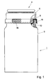
- the stopper bottle 1 comprises a bottle 2 and a stopper 4 which closes off an opening, being circular in this example, of the bottle.
- the stopper 4 is arranged to be pulled from the bottle for opening the bottle and to be pressed into the bottle for closing the bottle again.
- the stopper 4 is made up of a rigid upper cap 6 which, at its lower end, comprises a circumferential sidewall 8 which tapers downwardly in this example.
- the stopper comprises a lower cap 10 made of a flexible material, connected with the upper cap 6, having a sidewall 12 which is circumferential in this example.
- the sidewall 12 has likewise a conical shape, with the diameter of the lower cap decreasing in downward direction.
- the sidewall 8 of the upper cap extends downwardly into a space 14 enclosed by the lower cap 10.
- the sidewall 8 extends into a space enclosed by the sidewall 12 of the lower cap 10.
- the sidewall 12 of the lower cap extends into the opening 3 of the bottle 2.
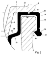
- the lower cap further comprises a skirt 16 which extends around a neck 18 of the bottle 2. At its upper end, the skirt 16 is connected via a tear line 20 with an upper end of the sidewall 12 of the lower cap 10. As can be properly seen in Fig. 2, in this example the profile of the skirt 16 corresponds with the profile of the neck 18 of the bottle 2. In this example, the skirt and the lower cap are made of the same material.
- the sidewall 8 of the upper cap 6 comprises, adjacent the tear line 20, an outwardly offset shoulder 22.
- the sidewall 12 of the lower cap 10 here merges at its upper end into a bent portion 24 extending outwardly in radial direction along the underside of the shoulder 22, with an outermost portion 26 of the bent portion 24 connected to the skirt 16.
- the bent portion 24, in this example, extends at least substantially in horizontal direction.
- the tear line 20 extends roundabout along the neck of the bottle in the bent portion 24.
- the skirt Adjacent its lower end 28, the skirt further comprises an edge 30 extending outwardly in radial direction. Further, the bottle 2 comprises, above this edge 30, a neck edge 32 bottle 2 comprises, above this edge 30, a neck edge 32 extending outwards and to above the edge of the skirt. It further appears from Fig. 2 that the skirt, adjacent its lower end, further comprises a circumferential edge 34 extending outwardly in radial direction. As can be properly seen in Fig. 3, the skirt further comprises on its outer side a lip 36 for tearing loose the skirt 16 from the rest of the lower cap 10.
- the stopper 4 cannot be removed from the bottle as long as the skirt 16 is present.
- the skirt 16 is even made of shrink foil, with the result that it is pulled tightly around the neck of the bottle.
- the edge 30 hooks under the neck edge 32, rendering it entirely impossible, even when applying great force, to pull the stopper 4 from the bottle.
- a consumer after he has purchased the bottle 1, wishes to remove the stopper 4 from the bottle 2, he does so by gripping the lip 36 and tearing the skirt 16 loose from the remainder of the lower cap 10 along the tear line 20.
- the bottle 2 can be opened by pulling the stopper 4 off the bottle.
- the stopper 4 can also be re-placed again, with the lower cap, owing to its flexibility, forming a proper seal again with the opening 3 of the bottle 2.
- the skirt may have been open. Accordingly, when upon purchase of a stopper bottle, the skirt is still present, a consumer can be certain that the bottle has not been open yet.
- a stopper bottle as described hereinabove can be carried out very simply.
- the lower cap is placed on the bottle, together with the skirt already attached to it. This results in a situation according to Fig. 1, with the upper cap omitted.
- Placing the lower cap on the bottle can be easily carried out because the lower cap is made of a flexible material.
- at least the skirt comprises a material which shrinks upon supply of heat. Accordingly, by supplying heat to the skirt of the lower cap, it can cling firmly around the neck of the bottle 2.
- the upper cap Before or after the skirt is, optionally, heated, the upper cap can be pressed tightly onto the lower cap.
- the upper cap and lower cap are thereby connected to each other via a snap connection, known per se, which has been utilized in stopper bottles for a long time already. This snap connection has the property of subsequently disallowing the upper cap 6 to be pulled from the lower cap.
- the invention is not limited to the embodiments outlined hereinbefore.
- the opening of the bottle can have a shape different from the circular shape.
- the opening can be, for instance, of square or hexagonal design.
- the stopper 4 will then have a shape corresponding to that of the opening. Such variants are all understood to fall within the scope of the invention.
Landscapes
- Engineering & Computer Science (AREA)
- Mechanical Engineering (AREA)
- Closures For Containers (AREA)
Abstract
Description
- This invention relates to a stopper bottle comprising a bottle with an opening and a stopper, detachably connected with the bottle, which closes the opening, the stopper being arranged to be pulled from the bottle for opening the bottle and to be pressed into the opening of the bottle for closing the bottle again, the stopper being made up of a rigid upper cap and a lower cap, made of flexible material and connected with the upper cap, a sidewall of the upper cap extending downwards into a space enclosed by the lower cap, and a sidewall of the lower cap extending into the opening of the bottle. For years already, such stopper bottles have been used for packaging ground coffee or instant coffee.
- A disadvantage of the known stopper bottle is that the stopper bottle, before being purchased by a consumer, that is, when, for instance, it is still on the shelf in a shop or in a storehouse of a supplier, can be opened by pulling the stopper from the bottle and subsequently be closed again by placing the stopper back onto the bottle again without this being evident from the bottle. Today's society, however, requires more and more that a stopper bottle, before being opened by a consumer, cannot be opened and subsequently closed again without this being evident from the bottle. To meet this problem, it has heretofore been proposed to provide a sleeve made of shrink foil around the neck of the bottle and the stopper. A disadvantage is, however, that such a sleeve can still be removed and re-placed without this being noticeable. It is also known to apply a seal which connects the stopper and the bottle with each other. It has been found, however, that the seal can be cut with a knife without the consumer subsequently noticing this.
- The object of the invention is to provide a stopper bottle which obviates the above-mentioned disadvantages. Accordingly, the invention is characterized in that the lower cap further comprises a skirt which extends around a neck of the bottle and which, at its upper end, is connected via a tear line with an upper end of the sidewall of the lower cap, and opening the bottle for the first time requires pulling the skirt from the sidewall of the lower cap along the tear line. Such a construction allows the cap to be removed from the bottle only when the skirt is pulled from the rest of the cap via the tear line. When the skirt is absent, however, it will be immediately clear to a consumer that the bottle may have been opened. Thus, accordingly, a stopper bottle has been obtained, which precludes the possibility of its being opened by pulling the stopper from the bottle without this being noticeable.
- Preferably, the skirt and the lower cap are made of the same material.
- The invention also relates to a method for manufacturing a stopper bottle as described above. According to the method of the invention, the lower cap comprising the skirt is placed on the bottle, such that the sidewall of the lower cap extends into the opening of the bottle, and the skirt extends around the neck of the bottle. Then the upper cap is pressed tightly onto the lower cap. In particular, the lower cap may then further be heated, so that the skirt shrinks and clings tightly around the neck of the bottle, before the upper cap is placed on the lower cap or after the upper cap is placed on the lower cap.
- The invention will presently be further elucidated with reference to the drawings, wherein:
- Fig. 1 is a partly transparent view of a stopper bottle according to the invention;
- Fig. 2 is a cross section of the part of the stopper bottle according to Fig. 1 that is shown in transparent view in Fig. 1; and
- Fig. 3 is a detail view of another part of the stopper bottle according to Fig. 1.
-
- The
stopper bottle 1 comprises abottle 2 and astopper 4 which closes off an opening, being circular in this example, of the bottle. Thestopper 4 is arranged to be pulled from the bottle for opening the bottle and to be pressed into the bottle for closing the bottle again. Thestopper 4 is made up of a rigidupper cap 6 which, at its lower end, comprises acircumferential sidewall 8 which tapers downwardly in this example. Further, the stopper comprises alower cap 10 made of a flexible material, connected with theupper cap 6, having asidewall 12 which is circumferential in this example. Thesidewall 12 has likewise a conical shape, with the diameter of the lower cap decreasing in downward direction. Thesidewall 8 of the upper cap extends downwardly into aspace 14 enclosed by thelower cap 10. In particular, thesidewall 8 extends into a space enclosed by thesidewall 12 of thelower cap 10. In this example, thesidewall 12 of the lower cap extends into theopening 3 of thebottle 2. - The lower cap further comprises a
skirt 16 which extends around aneck 18 of thebottle 2. At its upper end, theskirt 16 is connected via atear line 20 with an upper end of thesidewall 12 of thelower cap 10. As can be properly seen in Fig. 2, in this example the profile of theskirt 16 corresponds with the profile of theneck 18 of thebottle 2. In this example, the skirt and the lower cap are made of the same material. - The
sidewall 8 of theupper cap 6 comprises, adjacent thetear line 20, an outwardlyoffset shoulder 22. Thesidewall 12 of thelower cap 10 here merges at its upper end into abent portion 24 extending outwardly in radial direction along the underside of theshoulder 22, with anoutermost portion 26 of thebent portion 24 connected to theskirt 16. Thebent portion 24, in this example, extends at least substantially in horizontal direction. Thetear line 20 extends roundabout along the neck of the bottle in thebent portion 24. - Adjacent its
lower end 28, the skirt further comprises anedge 30 extending outwardly in radial direction. Further, thebottle 2 comprises, above thisedge 30, aneck edge 32bottle 2 comprises, above thisedge 30, aneck edge 32 extending outwards and to above the edge of the skirt. It further appears from Fig. 2 that the skirt, adjacent its lower end, further comprises acircumferential edge 34 extending outwardly in radial direction. As can be properly seen in Fig. 3, the skirt further comprises on its outer side alip 36 for tearing loose theskirt 16 from the rest of thelower cap 10. - In the bottle according to Figs. 1-3, the
stopper 4 cannot be removed from the bottle as long as theskirt 16 is present. In this example, theskirt 16 is even made of shrink foil, with the result that it is pulled tightly around the neck of the bottle. When someone tries to pull thestopper 4 from the bottle, he will not succeed in doing so, as theskirt 16 blocks this movement. Further, theedge 30 hooks under theneck edge 32, rendering it entirely impossible, even when applying great force, to pull thestopper 4 from the bottle. When a consumer, after he has purchased thebottle 1, wishes to remove thestopper 4 from thebottle 2, he does so by gripping thelip 36 and tearing theskirt 16 loose from the remainder of thelower cap 10 along thetear line 20. After the skirt has been removed, thebottle 2 can be opened by pulling thestopper 4 off the bottle. Thestopper 4 can also be re-placed again, with the lower cap, owing to its flexibility, forming a proper seal again with theopening 3 of thebottle 2. Obviously, it will be immediately clear to a consumer that when the skirt is removed, the bottle may have been open. Accordingly, when upon purchase of a stopper bottle, the skirt is still present, a consumer can be certain that the bottle has not been open yet. - Manufacturing a stopper bottle as described hereinabove can be carried out very simply. The lower cap is placed on the bottle, together with the skirt already attached to it. This results in a situation according to Fig. 1, with the upper cap omitted. Placing the lower cap on the bottle can be easily carried out because the lower cap is made of a flexible material. Preferably, at least the skirt comprises a material which shrinks upon supply of heat. Accordingly, by supplying heat to the skirt of the lower cap, it can cling firmly around the neck of the
bottle 2. Before or after the skirt is, optionally, heated, the upper cap can be pressed tightly onto the lower cap. The upper cap and lower cap are thereby connected to each other via a snap connection, known per se, which has been utilized in stopper bottles for a long time already. This snap connection has the property of subsequently disallowing theupper cap 6 to be pulled from the lower cap. - The invention is not limited to the embodiments outlined hereinbefore. Thus, it is possible for the opening of the bottle to have a shape different from the circular shape. The opening can be, for instance, of square or hexagonal design. The
stopper 4 will then have a shape corresponding to that of the opening. Such variants are all understood to fall within the scope of the invention.
Claims (13)
- A stopper bottle comprising a bottle with an opening, and a stopper, detachably connected with the bottle, which closes the opening, the stopper being arranged to be pulled from the bottle for opening the bottle and to be pressed into the opening of the bottle for closing the bottle again, the stopper being made up of a rigid upper cap and a lower cap, made of flexible material and connected with the upper cap, a sidewall of the upper cap extending downwards into a space enclosed by the lower cap, and a sidewall of the lower cap extending into the opening of the bottle, characterized in that the lower cap further comprises a skirt which extends around a neck of the bottle and which, at its upper end, is connected via a tear line with an upper end of the sidewall of the lower cap, and opening the bottle for the first time requires pulling the skirt from the sidewall of the lower cap along the tear line.
- A stopper bottle according to claim 1, characterized in that the profile of the skirt corresponds to the profile of the neck of the bottle.
- A stopper bottle according to claim 1 or 2, characterized in that the skirt and the lower cap are made of the same material.
- A stopper bottle according to any one of the preceding claims, characterized in that the opening of the bottle is circular.
- A stopper bottle according to any one of the preceding claims, characterized in that the sidewall of the upper cap comprises, adjacent the tear line, an outwardly offset shoulder, the sidewall of the lower cap bending at its upper end to merge into a bent portion extending outwardly in radial direction along the underside of the shoulder of the upper cap, an outermost portion of the bent portion being connected with the skirt.
- A stopper bottle according to claim 5, characterized in that the bent portion extends at least substantially in horizontal direction.
- A stopper bottle according to claim 6, characterized in that the tear line extends around the neck of the bottle in the bent portion.
- A stopper bottle according to any one of the preceding claims, characterized in that the skirt, adjacent its lower end, is provided with an edge extending inwardly in radial direction, and that the bottle, above the edge of the skirt, is provided with an edge extending outwardly and to above the edge of the skirt.
- A stopper bottle according to claim 8, characterized in that the skirt, adjacent its lower end, further comprises a circumferential edge extending outwardly in radial direction.
- A stopper bottle according to any one of the preceding claims, characterized in that the skirt, on the outer side thereof, is provided with a lip for tearing the skirt loose from the remainder of the lower cap.
- A stopper bottle according to any one of the preceding claims, characterized in that the lower cap is made of a material shrunk by a heat treatment.
- A method for manufacturing a stopper bottle according to any one of the preceding claims, characterized in that the method comprises the steps of placing the lower cap including the skirt on the bottle, such that the sidewall of the lower cap extends into the opening of the bottle and the skirt extends around the neck of the bottle; pressing the upper cap tightly onto the lower cap.
- A method according to claim 12, characterized in that the lower cap is heated, so that the skirt shrinks and clings tightly around the neck of the bottle.
Applications Claiming Priority (2)
| Application Number | Priority Date | Filing Date | Title |
|---|---|---|---|
| NL1007193 | 1997-10-01 | ||
| NL1007193A NL1007193C2 (en) | 1997-10-01 | 1997-10-01 | Stopper bottle. |
Publications (1)
| Publication Number | Publication Date |
|---|---|
| EP0906867A1 true EP0906867A1 (en) | 1999-04-07 |
Family
ID=19765782
Family Applications (1)
| Application Number | Title | Priority Date | Filing Date |
|---|---|---|---|
| EP98203310A Withdrawn EP0906867A1 (en) | 1997-10-01 | 1998-09-30 | Stopper bottle |
Country Status (3)
| Country | Link |
|---|---|
| EP (1) | EP0906867A1 (en) |
| AU (1) | AU8716498A (en) |
| NL (1) | NL1007193C2 (en) |
Citations (1)
| Publication number | Priority date | Publication date | Assignee | Title |
|---|---|---|---|---|
| DE7423290U (en) * | 1974-07-09 | 1974-11-21 | Hesser Ag Maschf | World neck bottle with stopper |
-
1997
- 1997-10-01 NL NL1007193A patent/NL1007193C2/en not_active IP Right Cessation
-
1998
- 1998-09-30 AU AU87164/98A patent/AU8716498A/en not_active Abandoned
- 1998-09-30 EP EP98203310A patent/EP0906867A1/en not_active Withdrawn
Patent Citations (1)
| Publication number | Priority date | Publication date | Assignee | Title |
|---|---|---|---|---|
| DE7423290U (en) * | 1974-07-09 | 1974-11-21 | Hesser Ag Maschf | World neck bottle with stopper |
Also Published As
| Publication number | Publication date |
|---|---|
| AU8716498A (en) | 1999-04-22 |
| NL1007193C2 (en) | 1999-04-07 |
Similar Documents
| Publication | Publication Date | Title |
|---|---|---|
| US10618721B2 (en) | Container with encircling graphic and process for producing | |
| US5624623A (en) | Method of making an inwardly directed projection on a plastic container | |
| US5528814A (en) | Container with curled tamper-evident band to retain closure | |
| EP2490955B1 (en) | Beverage can accessory | |
| US20050133508A1 (en) | Tamper evident lid welded to a container | |
| US6375023B1 (en) | Press-on/pry-off composite closure with removal-assist and method of making same | |
| EP0245894A1 (en) | Container having a detachably fastened lid | |
| USRE36729E (en) | Container with curled tamper-evident band to retain closure | |
| AU2001247855A1 (en) | Composite closure with removal assist and method | |
| CA2448474C (en) | Single-serving package and device for producing an aromatic beverage | |
| US4821913A (en) | Tamper evident cover | |
| US5119965A (en) | Dressing capsule for bottle | |
| EP0906867A1 (en) | Stopper bottle | |
| MX2007013999A (en) | Stopper device for the neck of a container container provided with such a device method for stopping such a container and method for prodcution of such a device. | |
| US10017302B2 (en) | Cap and tear ring for beverage bottle | |
| US20060150579A1 (en) | Method for forming a security stopper-capsule and applying it to containers with a threaded mouth, and the stopper-capsule obtained thereby | |
| EP1404586B1 (en) | Lid | |
| EP2019047A1 (en) | Device to fix a drinking glass on a bottle | |
| JP3753807B2 (en) | Container with lid | |
| EP0829429B1 (en) | Cap for oil bottles and the like | |
| EP0176159A1 (en) | Container with a closure releasably locked thereon | |
| JPS6140670Y2 (en) | ||
| EP0758985B2 (en) | Package | |
| US4457439A (en) | Tamperproof closure made of plastics material | |
| EP1473244A1 (en) | Cover element for containers such as cans and the like |
Legal Events
| Date | Code | Title | Description |
|---|---|---|---|
| PUAI | Public reference made under article 153(3) epc to a published international application that has entered the european phase |
Free format text: ORIGINAL CODE: 0009012 |
|
| AK | Designated contracting states |
Kind code of ref document: A1 Designated state(s): AT BE DK ES FI GB GR IE LU NL SE Kind code of ref document: A1 Designated state(s): BE DK ES FI GB GR IE LU NL SE |
|
| AX | Request for extension of the european patent |
Free format text: AL;LT;LV;MK;RO;SI |
|
| AKX | Designation fees paid |
Free format text: AT BE DK ES FI GB GR IE LU NL SE |
|
| 17P | Request for examination filed |
Effective date: 19991007 |
|
| RBV | Designated contracting states (corrected) |
Designated state(s): BE DK ES FI GB GR IE LU NL SE |
|
| REG | Reference to a national code |
Ref country code: DE Ref legal event code: 8566 |
|
| STAA | Information on the status of an ep patent application or granted ep patent |
Free format text: STATUS: THE APPLICATION IS DEEMED TO BE WITHDRAWN |
|
| 18D | Application deemed to be withdrawn |
Effective date: 20010403 |