EP0906778A1 - Rollenkörper aus Verbundwerkstoff für kontinuierliches Bandsystem zur Trennung von Bohrschlamm - Google Patents
Rollenkörper aus Verbundwerkstoff für kontinuierliches Bandsystem zur Trennung von Bohrschlamm Download PDFInfo
- Publication number
- EP0906778A1 EP0906778A1 EP98307714A EP98307714A EP0906778A1 EP 0906778 A1 EP0906778 A1 EP 0906778A1 EP 98307714 A EP98307714 A EP 98307714A EP 98307714 A EP98307714 A EP 98307714A EP 0906778 A1 EP0906778 A1 EP 0906778A1
- Authority
- EP
- European Patent Office
- Prior art keywords
- belt
- drilling mud
- drive roller
- teeth
- mud separation
- Prior art date
- Legal status (The legal status is an assumption and is not a legal conclusion. Google has not performed a legal analysis and makes no representation as to the accuracy of the status listed.)
- Granted
Links
- 238000005553 drilling Methods 0.000 title claims abstract description 59
- 238000000926 separation method Methods 0.000 title claims abstract description 29
- 239000002131 composite material Substances 0.000 title abstract description 15
- 239000012530 fluid Substances 0.000 claims abstract description 23
- 239000013536 elastomeric material Substances 0.000 claims abstract description 19
- 239000002184 metal Substances 0.000 claims abstract description 13
- 239000002245 particle Substances 0.000 claims abstract description 13
- 239000007788 liquid Substances 0.000 claims abstract description 10
- 239000000463 material Substances 0.000 claims description 3
- 230000001419 dependent effect Effects 0.000 claims description 2
- 239000007787 solid Substances 0.000 abstract description 24
- 235000003934 Abelmoschus esculentus Nutrition 0.000 abstract description 10
- 240000004507 Abelmoschus esculentus Species 0.000 abstract description 10
- 238000005520 cutting process Methods 0.000 description 7
- 238000004140 cleaning Methods 0.000 description 6
- 125000006850 spacer group Chemical group 0.000 description 4
- JOYRKODLDBILNP-UHFFFAOYSA-N Ethyl urethane Chemical compound CCOC(N)=O JOYRKODLDBILNP-UHFFFAOYSA-N 0.000 description 2
- 230000015572 biosynthetic process Effects 0.000 description 2
- 238000005755 formation reaction Methods 0.000 description 2
- 230000005923 long-lasting effect Effects 0.000 description 2
- 238000011109 contamination Methods 0.000 description 1
- 238000003306 harvesting Methods 0.000 description 1
- 231100001261 hazardous Toxicity 0.000 description 1
- 238000003754 machining Methods 0.000 description 1
- 239000011860 particles by size Substances 0.000 description 1
- 230000035515 penetration Effects 0.000 description 1
- 238000012216 screening Methods 0.000 description 1
- 239000002689 soil Substances 0.000 description 1
- 239000007921 spray Substances 0.000 description 1
- XLYOFNOQVPJJNP-UHFFFAOYSA-N water Substances O XLYOFNOQVPJJNP-UHFFFAOYSA-N 0.000 description 1
Images


Classifications
-
- B—PERFORMING OPERATIONS; TRANSPORTING
- B01—PHYSICAL OR CHEMICAL PROCESSES OR APPARATUS IN GENERAL
- B01D—SEPARATION
- B01D33/00—Filters with filtering elements which move during the filtering operation
- B01D33/04—Filters with filtering elements which move during the filtering operation with filtering bands or the like supported on cylinders which are impervious for filtering
-
- B—PERFORMING OPERATIONS; TRANSPORTING
- B01—PHYSICAL OR CHEMICAL PROCESSES OR APPARATUS IN GENERAL
- B01D—SEPARATION
- B01D33/00—Filters with filtering elements which move during the filtering operation
- B01D33/056—Construction of filtering bands or supporting belts, e.g. devices for centering, mounting or sealing the filtering bands or the supporting belts
-
- B—PERFORMING OPERATIONS; TRANSPORTING
- B01—PHYSICAL OR CHEMICAL PROCESSES OR APPARATUS IN GENERAL
- B01D—SEPARATION
- B01D33/00—Filters with filtering elements which move during the filtering operation
- B01D33/27—Filters with filtering elements which move during the filtering operation with rotary filtering surfaces, which are neither cylindrical nor planar, e.g. helical surfaces
- B01D33/275—Filters with filtering elements which move during the filtering operation with rotary filtering surfaces, which are neither cylindrical nor planar, e.g. helical surfaces using contiguous impervious surfaces
-
- B—PERFORMING OPERATIONS; TRANSPORTING
- B01—PHYSICAL OR CHEMICAL PROCESSES OR APPARATUS IN GENERAL
- B01D—SEPARATION
- B01D33/00—Filters with filtering elements which move during the filtering operation
- B01D33/44—Regenerating the filter material in the filter
- B01D33/46—Regenerating the filter material in the filter by scrapers, brushes nozzles or the like acting on the cake-side of the filtering element
- B01D33/465—Regenerating the filter material in the filter by scrapers, brushes nozzles or the like acting on the cake-side of the filtering element take-off rollers
-
- B—PERFORMING OPERATIONS; TRANSPORTING
- B01—PHYSICAL OR CHEMICAL PROCESSES OR APPARATUS IN GENERAL
- B01D—SEPARATION
- B01D2201/00—Details relating to filtering apparatus
- B01D2201/08—Regeneration of the filter
- B01D2201/089—Regeneration of the filter using rollers having projections to clear the filter apertures
Definitions
- This invention relates generally to drive rollers and drilling mud separation units, and more particularly to cylindrical composite rollers having a thick elastomeric outer layer for use in an endless-belt drilling mud separation unit, and a drive roller having a plurality axially spaced circumferential rows of radially extending elastomeric teeth that receive and engage the openings in a wide belt formed of a plurality of laterally adjacent hinged links to drive the belt and reduce wear, prevent sparking, and dislodge materials which may otherwise clog the belt openings.
- the shale shakers and mud cleaners employ a vibrating screen to selectively classify particles by size differences.
- the desander, desilter, and centrifuge are usually located downstream from the shale shaker and utilize centrifugal force and mass difference between the solids density and liquid density for solids removal.
- the initial removal step in most solids control systems is to conduct the drilling mud from the well directly to a shale shaker. Vibrating screen shale shakers of the type used in the oil industry fall into three general categories, as described below.
- “Circular motion,” or “balanced design” shakers produce a balanced, or generally circular motion.
- the consistent, circular vibration allows solids transport with the basket in a flat, horizontal orientation.
- This type of shaker usually has multiple decks to split the solids load and allows the use of finer mesh screens in the range of 80-100 mesh (150-180 microns).
- Linear motion shakers produce a generally straight motion. This motion is developed by a pair of eccentric shafts rotating in opposite directions. Linear motion shakers provide superior cutting conveyance and are able to operate at an uphill slope which allows the use of 200 mesh screens (77 microns).
- U.S. Patent No. 4,146,483 discloses a segmented endless belt vibrating screen for removing solid particles from a stream of drilling fluid circulated therethrough.
- the screen assembly is formed of laterally spaced segments of one or more layers of open mesh screens interconnected by longitudinal rubber support belts disposed therebetween and a pair of rubber strips along the outermost lateral side edges.
- the rubber strips along the outermost lateral side edges are connected by L-shaped hooks to a pair of rubber V-belts which are received in V-shaped rollers with one set of rollers driven by a motor.
- the mesh screens are cleaned by a set of nozzles which direct a spray of water onto the screen at a point prior to it passing over a rubber wiper.
- U.S. Patent 3,631,980 discloses an open mesh belt cleaner for cleaning the bight openings of a link screen conveyer belt in a pea-harvesting machine.
- the endless belt link screen is supported and driven by a sprocket at each lateral side of the belt which have teeth that engage the links of the belt.
- the belt cleaner comprises one or more bars which extend transversely between the sprockets and each bar replaces one of the teeth of the opposed sprockets.
- the bar is provided with a series of debris expelling metal teeth along its length in staggered registry with certain ones of the openings in the belt to penetrate the openings of different rows in successive passes of the belt.
- Hamacheck III states that it would be undesirable to employ the metal teeth to clean all the successive rows of belt openings in every pass of the belt.
- Embodiments of the present invention are distinguished over the prior art in general and these patents in particular by a pair of cylindrical composite rollers formed of a metallic drum with a thick outer elastomeric layer that are mounted transversely in a rectangular frame of a drilling mud separation unit over which a wide endless-loop chain-link belt is driven in a continuous loop moving along the longitudinal axis of the frame.
- the drive roller has a plurality of axially spaced circumferential rows of radially extending teeth that are machined in the surface of the elastomeric material.
- the endless belt is formed of a plurality of laterally adjacent jointed links hinged together by transverse rods.
- the teeth of the drive roller are sized and spaced to receive and engage the plurality of laterally adjacent jointed links of the wide belt and are of sufficient length to protrude slightly beyond the outer surface of the links as they pass around the front drive roller to dislodge gumbo and other large solids which may otherwise stick in the openings of the links and clog the belt.
- the elastomeric roller surfaces and teeth reduce wear and prevent metal-to-metal contact and sparking.
- a further advantage of this invention is to provide long-lasting composite rollers having an outer layer of elastomeric material which support and drive a wide continuous-belt around the rollers in a continuous loop.
- a still further advantage of this invention is to provide a long-lasting composite roller having an outer layer of elastomeric material with teeth formed in the elastomeric material that engage and continuously clean the openings in the links of a wide continuous-loop chain link belt as the belt completes its path.
- a pair of cylindrical composite rollers formed of a metallic drum with a thick outer elastomeric layer that are mounted transversely in a rectangular frame of a drilling mud separation unit over which a wide endless-loop chain-link belt is driven in a continuous loop moving along the longitudinal axis of the frame.
- the drive roller has a plurality of axially spaced circumferential rows of radially extending teeth that are machined in the surface of the elastomeric material.
- the endless belt is formed of a plurality of laterally adjacent jointed links hinged together by transverse rods.
- the teeth of the drive roller are sized and spaced to receive and engage the plurality of laterally adjacent jointed links of the wide belt and are of sufficient length to protrude slightly beyond the outer surface of the links as they pass around the front drive roller to dislodge gumbo and other large solids which may otherwise stick in the openings of the links and clog the belt.
- the elastomeric roller surfaces and teeth reduce wear and prevent metal-to-metal contact and sparking.
- the cylindrical composite rollers in accordance with the present invention are formed of a metallic drum having a thick outer layer of elastomeric material, preferably urethane, and are particularly suited for use in a self-cleaning continuous belt drilling mud separation system such as the one described in copending U.S. Patent Application Serial No. 08/848,807, which is hereby incorporated herein by reference.
- the drilling mud separation unit 10 in which the rollers are to be installed has a generally rectangular outer frame assembly 11 formed of side and rear C-shaped channel members 11A and 11B, respectively, that supports an inner front tensioning frame assembly 12, an inner rear tensioning frame assembly 26, and other components.
- the separation unit 10 is shown in an unassembled condition in Figure 1, and in an assembled condition in Figure 2.
- the endless-loop chain link belt 17 is shown schematically in Figures 1 and 2, but is shown in greater detail in Figures 4 and 5.
- the inner front tensioning frame assembly 12 is a generally U-shaped configuration formed of a pair of laterally opposed rectangular side plate members 12A with a transverse rectangular crossmember plate 12B secured between the inner facing ends of the side plates. Front bearings 13 are mounted at the outer ends of the opposed plates 12A.
- the U-shaped inner front tensioning frame assembly 12 carrying the front bearings 13 and drive roller 42 is fixedly connected to the front end of the outer frame assembly 11 by spacer plates 19.
- the axle 14 of the front drive roller 42 is journalled in the front bearings 13 and its outer ends extend through the front bearings 13 and through the outer frame assembly 11 to receive a drive sheave 15 on either the right or left side of the outer frame 11.
- the drive sheave 15 can be located on either the left or the right side of the outer frame 11.
- a keyway 14A, key 14B, and retainer hub 15A secure the drive sheave 15 onto the axle 14.
- Lifting eyes 18 are secured to the front end of the outer frame assembly 11 to lift and move the separation unit 10 as required.
- the inner front tensioning frame assembly 12, spacer plates 19, and the front bearings 13 are attached to the outer frame assembly 11 to make the front of the separation unit 10 rigid.
- Holes 20 are located on the front of the outer frame assembly 11 to attach the inner front tensioning frame assembly 12, front bearings 13, and spacer plates 19.
- the inner rear tensioning frame assembly 26 is a generally H-shaped configuration formed of a pair of laterally opposed rectangular side plate members 26A with a transverse rectangular crossmember plate 26B secured between the side plates and laterally opposed end plates 26C secured near the front ends of the side plates.
- Rear bearings 27 are mounted at the rear ends of the opposed plates 26A.
- the axle 28 of the rear roller 29 is journalled in the bearings 27.
- the H-shaped inner rear tensioning frame assembly 26 carrying the rear bearings 27 and rear roller are not rigidly connected to outer frame assembly 11. Instead, the inner rear tensioning frame assembly 26 is slidably received in the C-shaped side channels of the outer frame 11.
- Tensioning cylinders 21 are mounted on the inner front tensioning frame assembly 12 and the outer ends of their piston rods 21A are connected to the end plates 26C at the front ends of the side plates 26B of the inner rear tensioning frame assembly 26.
- Fluid lines 22 connect the tensioning cylinders 21 to a reservoir 23 which is mounted on the transverse crossmember 12B of the inner front frame assembly 12.
- the reservoir 23 contains a fluid medium (air or hydraulic) with which to operate the tensioning cylinders 21.
- a fluid line 24 connected to the reservoir 23 extends through a mounting plate 25 attached to the side of the outer frame assembly 11.
- An air or hydraulic supply line from the rig may be connected to the line 24 to supply air or hydraulic fluid to the tensioning system.
- the outer ends of the piston rods 21A of the tensioning cylinders 21 are connected to the end plates 26C at the front ends of the side plates 26B of the inner rear frame assembly 26.
- the inner rear frame assembly 26 and rear roller 29 are moved along the C-shaped side channels of the outer frame 11 relative to the outer frame by the tensioning cylinders 21.
- the inner rear tensioning frame assembly 26 carrying the rear roller 29 slides relative to the outer frame 11 and inner front tensioning frame assembly 12 upon extension or retraction of the piston rods 21A of the tensioning cylinders 21.
- the piston rods 21A When the piston rods 21A are extended the inner rear frame assembly 26 and rear roller 29A move rearwardly to apply and maintain tension in the moving chain link belt 17.
- Tubular collars or spacers 50 pay be installed on the piston rods 21A to prevent them from retracting and maintain the tension in the belt 17.
- a pair of laterally opposed parallel elongate rectangular guide/support bars 43 are connected at one end to the crossmember 26B of the inner rear tensioning frame assembly 26 and extend forward toward the front of the separation unit 10 and over the crossmember 12B of the inner front tensioning frame assembly 12 to support the chin link belt 17.
- the guide/support bars 43 move with the inner rear tensioning frame assembly 26 relative to the outer frame 11 as tension is applied or relaxed by the tensioning cylinders 21.
- a pair of elongate flat guard rails 41 are mounted at the top ends of the C-shaped channels of the outer frame 11 after the moving chain link belt 17 is installed.
- the guard rails 41 extend inwardly from the sides of the outer frame assembly 11 over the lateral edges of the moving chain link belt 17 and forwardly over the lateral ends of the drive roller 42.
- the drive roller 42 and hence the chain link belt 17 is driven by a variable or fixed speed external motor (not shown) which is releasably connected to the drive sheave 15 on the outwardly extended end of the drive roller drive shaft 14.
- the separation unit 10 is installed in a box-like housing which is shown and described in copending U.S. Patent Application Serial No. 08/848,807, which is mounted in the flow path of the drilling mud or drilling fluids on a drilling rig and serves to operate the separation unit or units 10 to separate solids from drilling fluids or drilling muds obtained from a well bore.
- the wide endless-loop chain link belt 17 passes around the front drive roller 42 and rear roller 29.
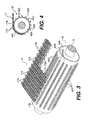
- the front drive roller 42 which is used to drive the wide chain link belt 17 has a plurality of axially spaced circumferential spaced rows of radially extending teeth 42C.
- the self-cleaning chain link belt 17 is a wide endless loop belt formed of a plurality of adjacent jointed chain links 17A hingedly connected together by a plurality of parallel spaced transversely extending rods 17B.
- the endless loop chain link belt 17 passes around the front drive roller 42 and rear roller 29.
- the teeth 42C of the drive roller 42 are sized and spaced to be received in the apertures of the jointed chain links 17A.
- the teeth 42C are of sufficient length to protrude slightly beyond the outer surface of the links 17A as they pass around the front drive roller 42.
- the toothed front drive roller 42 and chain link belt 17 arrangement is particularly useful in removing gumbo and other large solids which may otherwise stick in the openings of the links and clog the belt.
- a rectangular wiper blade W formed of resilient elastomeric material sandwiched between two rectangular metal straps may be secured transversely across the front of the frame to wipe the outer surface of the chain link belt 17 as it passes around the drive roller 42.
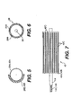
- FIGS 5, 6, 7, and 8 illustrate preferred embodiments of the composite rear roller 29 and front drive roller 42 which are mounted at opposite ends of the frame of the drilling mud separation unit described above and over which the wide endless-loop chain link belt 17 passes.
- the rear roller 29 ( Figures 5 and 6) is formed of a cylindrical metal drum 29A approximately 22" to 24" in length having an outer diameter of from about 73 ⁇ 8" to about 71 ⁇ 2" and an outer layer 29B of elastomeric material of from about 1" to about 17 ⁇ 8" thick molded or bonded onto its exterior surface.
- the outer ends of the roller are enclosed by circular end plates having a central collar or aperture through which the axle is secured to extend outwardly from each end.
- the rear roller 29 ( Figure 6) has a smooth outer layer of elastomeric material.
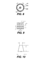
- the toothed drive roller 43 ( Figures 7 and 8) is also formed of a cylindrical metal drum 42A approximately 22" to 24" in length having an outer diameter of from about 73 ⁇ 8" to about 71 ⁇ 2" and an outer layer 42B of elastomeric material of from about 1" to about 17 ⁇ 8" thick molded or bonded onto the exterior surface of the drum and its outer ends are enclosed by circular end plates having a central collar through which an axle is secured to extend outwardly from each end and one outer end of its axle is provided with a keyway.
- FIGS 7, 8, 9, and 10 illustrate one example of a typical tooth arrangement and tooth profile.
- Each tooth has a transverse thickness of about 14.6mm (0.575”) and tapers upwardly to a height of about 14.6mm (0.575") to form an included pressure angle of about 35°27' between the opposed slanted surfaces.
- the foregoing tooth description is merely one example of a toothed surface, and that many other variations may be made, depending upon the particular application, type of endless belt used, and rotational speed, without departing from the scope of the present invention.
- the rows of teeth may be arranged in one or more spirals encircling the drum and may be of different profiles, i.e., round, square, dovetail, triangle, rectangle, parallelogram, hexagon, or octagon, etc.
- the transverse and longitudinal cross section area of the urethane teeth should be sufficient to withstand torquing, side load, back load, torsional twisting, and temperature.
- the included angle of the teeth should be sufficient to provide clearance between the apertures of the belt and be self cleaning as the roller rotates.
- the pressure angle of the teeth would also be a determining factor as to such things as the number of teeth, number of rows, the tooth profile, and pitch or lead.
- the composite rollers of the present invention are utilized with the wide endless-loop chain link belt to remove large drill solids, heavy clays, and gumbo (sticking clays) from the drilling mud or drilling fluid prior to the drilling fluid or drilling mud flowing to conventional solids control equipment such as shale shakers to lessen the stoppage of flow of drilling mud and drilling fluids in their flow lines which thereby improves the performance of such equipment and reduces the cost of drilling operations.
- the elastomeric roller surfaces and teeth reduce wear and prevent metal-to-metal contact and sparking.
- the moving chain link belt 17 is rotated around the drive roller 42 in an endless loop and passes underneath the separation unit 10 towards the rear roller 29.
- the moving chain link belt 17 then passes around the rear roller 29 and moves underneath the flow of drilling mud or filling fluid from the well bore where large solids and gumbo from the well bore area deposited on the moving chain link belt 17.
- the moving chain link belt 17 continues forward movement across the guide/support bars 43 to the front drive roller 42.
- the large drill solids and gumbo are discharged off the moving chain link belt 17 into a suitable discharge receptacle, pipe, conveyor, or other means as may be provided at each unit location.
- the teeth 42C of the drive roller 42 are received in the apertures of the jointed chain links 17A and protrude therethrough to dislodge and remove gumbo and other large solids which may be stuck in the openings of the links to clean and unclog the belt in each pass of the links 17A around the front drive roller.
- the moving chain link belt 17 may be varied in size of spacing between links, joints, mesh or along with the toothed arrangement of the drive roller 42.
Landscapes
- Chemical & Material Sciences (AREA)
- Chemical Kinetics & Catalysis (AREA)
- Separation Of Solids By Using Liquids Or Pneumatic Power (AREA)
- Filtration Of Liquid (AREA)
- Combined Means For Separation Of Solids (AREA)
- Perforating, Stamping-Out Or Severing By Means Other Than Cutting (AREA)
Applications Claiming Priority (2)
| Application Number | Priority Date | Filing Date | Title |
|---|---|---|---|
| US6094197P | 1997-10-03 | 1997-10-03 | |
| US60941P | 1997-10-03 |
Publications (2)
| Publication Number | Publication Date |
|---|---|
| EP0906778A1 true EP0906778A1 (de) | 1999-04-07 |
| EP0906778B1 EP0906778B1 (de) | 2002-07-24 |
Family
ID=22032690
Family Applications (1)
| Application Number | Title | Priority Date | Filing Date |
|---|---|---|---|
| EP98307714A Expired - Lifetime EP0906778B1 (de) | 1997-10-03 | 1998-09-23 | Rollenkörper aus Verbundwerkstoff für kontinuierliches Bandsystem zur Trennung von Bohrschlamm |
Country Status (9)
| Country | Link |
|---|---|
| US (1) | US6105785A (de) |
| EP (1) | EP0906778B1 (de) |
| JP (1) | JP3981211B2 (de) |
| BR (1) | BR9803954B1 (de) |
| CA (1) | CA2249047C (de) |
| DE (1) | DE69806708T2 (de) |
| DK (1) | DK0906778T3 (de) |
| NO (1) | NO314198B1 (de) |
| SG (1) | SG74659A1 (de) |
Cited By (2)
| Publication number | Priority date | Publication date | Assignee | Title |
|---|---|---|---|---|
| NO20110438A1 (no) * | 2011-03-23 | 2012-02-20 | Cubility As | Framgangsmåte for å overvåke integriteten til en siktinnretning og apparat for utøvelse av framgangsmåten |
| EP2659945A1 (de) * | 2012-05-02 | 2013-11-06 | Cambridge International, Inc. | Heißgasfiltrationssystem |
Families Citing this family (9)
| Publication number | Priority date | Publication date | Assignee | Title |
|---|---|---|---|---|
| KR20040009888A (ko) * | 2002-07-26 | 2004-01-31 | 주식회사 포스코 | 파쇄 스크린의 망 막힘방지장치 |
| US6910587B2 (en) * | 2002-08-02 | 2005-06-28 | Varco I/P, Inc. | Gumbo separator methods and apparatuses |
| US6811032B2 (en) * | 2003-01-16 | 2004-11-02 | Varco I/P, Inc. | Shaker roll screen |
| AU2006216497B2 (en) * | 2005-02-24 | 2011-07-21 | Laitram, L.L.C. | Modular screen belt |
| JP5762679B2 (ja) * | 2009-10-26 | 2015-08-12 | 株式会社新井機械製作所 | 食品生地の熱風乾燥装置 |
| US8905227B2 (en) * | 2012-06-20 | 2014-12-09 | Laitram, L.L.C. | Cleanable conveyor belt and carryway |
| US20180072601A1 (en) | 2016-09-12 | 2018-03-15 | Vermeer Manufacturing Company | Flat-wire belt conveyors |
| KR20180076440A (ko) * | 2016-12-28 | 2018-07-06 | 주식회사 링콘테크놀로지 | 준설물 투입용 무빙 스크린 장치 |
| CN110896933A (zh) * | 2019-11-27 | 2020-03-24 | 管伯青 | 一种海贝采挖机的挖掘头总成 |
Citations (4)
| Publication number | Priority date | Publication date | Assignee | Title |
|---|---|---|---|---|
| US2929507A (en) * | 1957-01-22 | 1960-03-22 | Komline Sanderson Eng Corp | Self-cleaning filter |
| FR1325859A (fr) * | 1962-03-23 | 1963-05-03 | Cie Generale Des Turbo Machine | Procédé et dispositif de protection pour canaux d'alimentation ou pour orifices d'aspiration dans un milieu liquide |
| US3631980A (en) * | 1969-08-04 | 1972-01-04 | Frank Hamachek Machine Co | Open mesh belt cleaner |
| GB2061751A (en) * | 1979-10-29 | 1981-05-20 | Howard G A | Fluid intake openings |
Family Cites Families (18)
| Publication number | Priority date | Publication date | Assignee | Title |
|---|---|---|---|---|
| US1151243A (en) * | 1915-04-01 | 1915-08-24 | Willis N Britton | Separator. |
| US1715197A (en) * | 1927-10-07 | 1929-05-28 | John D Grabill | Grading machine |
| US2784880A (en) * | 1954-07-12 | 1957-03-12 | Pio Albert Stevens | Machine for spreading peat moss and the like |
| US3851791A (en) * | 1970-12-16 | 1974-12-03 | Justrite Manufacturing Co | Plastic safety can for containing fires burning inflammable fluid inside the can |
| US3724285A (en) * | 1972-04-17 | 1973-04-03 | J Lapeyre | Conveyor drive |
| US3853016A (en) * | 1973-02-20 | 1974-12-10 | Gates Rubber Co | Crop gathering belt |
| US3866770A (en) * | 1974-03-08 | 1975-02-18 | Productive Acres Mfg Co | Conveying apparatus for a material handling vehicle |
| US4119295A (en) * | 1975-07-28 | 1978-10-10 | Blocker William C | Seal for LP gas cylinder valve |
| JPS5916593Y2 (ja) * | 1978-05-19 | 1984-05-15 | 本田技研工業株式会社 | チェン装置 |
| US4283184A (en) * | 1979-04-30 | 1981-08-11 | Winfred M. Berg, Inc. | Non-metallic silent chain |
| US4337672A (en) * | 1980-05-15 | 1982-07-06 | Samuel Shiber | Speed changing floating power transmission ring |
| US4836067A (en) * | 1984-01-16 | 1989-06-06 | Rogers Dale R | Protective socket insert |
| US4770711A (en) * | 1984-08-24 | 1988-09-13 | Petroleum Fermentations N.V. | Method for cleaning chemical sludge deposits of oil storage tanks |
| US5017969A (en) * | 1988-05-30 | 1991-05-21 | Canon Kabushiki Kaisha | Device having movable belt |
| US5200083A (en) * | 1991-10-16 | 1993-04-06 | Jannette Gomez Kaylor | Skimmer and method for its use |
| US5507382A (en) * | 1994-11-14 | 1996-04-16 | G. S. Blodgett Corporation | Belt stabilizer for pinch belt conveyor |
| CA2253350C (en) * | 1996-05-06 | 2003-01-28 | J. Terrell Williams | Continuous belt drilling mud separation system |
| US5921399A (en) * | 1996-06-07 | 1999-07-13 | Derrick Corporation | Gumbo separator |
-
1998
- 1998-09-03 US US09/146,938 patent/US6105785A/en not_active Expired - Lifetime
- 1998-09-17 SG SG1998003693A patent/SG74659A1/en unknown
- 1998-09-23 EP EP98307714A patent/EP0906778B1/de not_active Expired - Lifetime
- 1998-09-23 DE DE69806708T patent/DE69806708T2/de not_active Expired - Lifetime
- 1998-09-23 DK DK98307714T patent/DK0906778T3/da active
- 1998-09-29 CA CA002249047A patent/CA2249047C/en not_active Expired - Lifetime
- 1998-09-30 NO NO19984570A patent/NO314198B1/no not_active IP Right Cessation
- 1998-10-01 BR BRPI9803954-7A patent/BR9803954B1/pt active IP Right Grant
- 1998-10-02 JP JP28090098A patent/JP3981211B2/ja not_active Expired - Fee Related
Patent Citations (4)
| Publication number | Priority date | Publication date | Assignee | Title |
|---|---|---|---|---|
| US2929507A (en) * | 1957-01-22 | 1960-03-22 | Komline Sanderson Eng Corp | Self-cleaning filter |
| FR1325859A (fr) * | 1962-03-23 | 1963-05-03 | Cie Generale Des Turbo Machine | Procédé et dispositif de protection pour canaux d'alimentation ou pour orifices d'aspiration dans un milieu liquide |
| US3631980A (en) * | 1969-08-04 | 1972-01-04 | Frank Hamachek Machine Co | Open mesh belt cleaner |
| GB2061751A (en) * | 1979-10-29 | 1981-05-20 | Howard G A | Fluid intake openings |
Cited By (6)
| Publication number | Priority date | Publication date | Assignee | Title |
|---|---|---|---|---|
| NO20110438A1 (no) * | 2011-03-23 | 2012-02-20 | Cubility As | Framgangsmåte for å overvåke integriteten til en siktinnretning og apparat for utøvelse av framgangsmåten |
| WO2012128641A1 (en) * | 2011-03-23 | 2012-09-27 | Cubility As | Method for monitoring the integrity of a sieve device and apparatus for practice of the method |
| GB2503373A (en) * | 2011-03-23 | 2013-12-25 | Cubility As | Method for monitoring the integrity of a sieve device and apparatus for practice of the method |
| US9242276B2 (en) | 2011-03-23 | 2016-01-26 | Cubility As | Method for monitoring the integrity of a sieve device and apparatus for practice of the method |
| GB2503373B (en) * | 2011-03-23 | 2017-05-31 | Cubility As | Method for monitoring the integrity of a sieve device and apparatus for practice of the method |
| EP2659945A1 (de) * | 2012-05-02 | 2013-11-06 | Cambridge International, Inc. | Heißgasfiltrationssystem |
Also Published As
| Publication number | Publication date |
|---|---|
| DE69806708T2 (de) | 2003-04-03 |
| BR9803954B1 (pt) | 2008-11-18 |
| NO314198B1 (no) | 2003-02-10 |
| CA2249047A1 (en) | 1999-04-03 |
| CA2249047C (en) | 2006-09-05 |
| NO984570D0 (no) | 1998-09-30 |
| NO984570L (no) | 1999-04-06 |
| EP0906778B1 (de) | 2002-07-24 |
| BR9803954A (pt) | 1999-12-21 |
| JPH11165133A (ja) | 1999-06-22 |
| DE69806708D1 (de) | 2002-08-29 |
| US6105785A (en) | 2000-08-22 |
| DK0906778T3 (da) | 2003-04-14 |
| SG74659A1 (en) | 2000-08-22 |
| JP3981211B2 (ja) | 2007-09-26 |
Similar Documents
| Publication | Publication Date | Title |
|---|---|---|
| US6220445B1 (en) | Self-cleaning continuous-belt drilling mud separation system | |
| EP0908599B1 (de) | Bypass Verteilerbehälter für eine Trennvorrichtung für Bohrspülung | |
| EP0912257B1 (de) | Gumbo-abscheider | |
| US4146483A (en) | Vibrating screen | |
| US6186337B1 (en) | Dual screen element having upper scalping screen adhered to crests of corrugated lower screen | |
| US6105785A (en) | Composite rollers for continuous-belt drilling mud separation unit | |
| EP0907003A1 (de) | Strömungsverteilerkasten zur Bohrschlammleitung zu ausgewählten Trennungsbohrschlammeinheiten | |
| CA2664446A1 (en) | Peripheral sealing system for pre-tensioned screens | |
| US5996387A (en) | Method and apparatus for pre-stretching continuous chain-link drilling mud separation belt | |
| US6910587B2 (en) | Gumbo separator methods and apparatuses | |
| WO2001039861A1 (en) | A method of making a screen, a screen, and a system for making a screen | |
| WO2020256921A1 (en) | Vibratory separators |
Legal Events
| Date | Code | Title | Description |
|---|---|---|---|
| PUAI | Public reference made under article 153(3) epc to a published international application that has entered the european phase |
Free format text: ORIGINAL CODE: 0009012 |
|
| AK | Designated contracting states |
Kind code of ref document: A1 Designated state(s): DE DK FR GB NL |
|
| AX | Request for extension of the european patent |
Free format text: AL;LT;LV;MK;RO;SI |
|
| 17P | Request for examination filed |
Effective date: 19991007 |
|
| AKX | Designation fees paid |
Free format text: DE DK FR GB NL |
|
| 17Q | First examination report despatched |
Effective date: 20000208 |
|
| GRAG | Despatch of communication of intention to grant |
Free format text: ORIGINAL CODE: EPIDOS AGRA |
|
| GRAG | Despatch of communication of intention to grant |
Free format text: ORIGINAL CODE: EPIDOS AGRA |
|
| GRAG | Despatch of communication of intention to grant |
Free format text: ORIGINAL CODE: EPIDOS AGRA |
|
| GRAH | Despatch of communication of intention to grant a patent |
Free format text: ORIGINAL CODE: EPIDOS IGRA |
|
| GRAH | Despatch of communication of intention to grant a patent |
Free format text: ORIGINAL CODE: EPIDOS IGRA |
|
| GRAH | Despatch of communication of intention to grant a patent |
Free format text: ORIGINAL CODE: EPIDOS IGRA |
|
| GRAA | (expected) grant |
Free format text: ORIGINAL CODE: 0009210 |
|
| AK | Designated contracting states |
Kind code of ref document: B1 Designated state(s): DE DK FR GB NL |
|
| REG | Reference to a national code |
Ref country code: GB Ref legal event code: FG4D |
|
| REF | Corresponds to: |
Ref document number: 69806708 Country of ref document: DE Date of ref document: 20020829 |
|
| ET | Fr: translation filed | ||
| REG | Reference to a national code |
Ref country code: DK Ref legal event code: T3 |
|
| PLBE | No opposition filed within time limit |
Free format text: ORIGINAL CODE: 0009261 |
|
| STAA | Information on the status of an ep patent application or granted ep patent |
Free format text: STATUS: NO OPPOSITION FILED WITHIN TIME LIMIT |
|
| 26N | No opposition filed |
Effective date: 20030425 |
|
| REG | Reference to a national code |
Ref country code: FR Ref legal event code: PLFP Year of fee payment: 19 |
|
| REG | Reference to a national code |
Ref country code: FR Ref legal event code: PLFP Year of fee payment: 20 |
|
| PGFP | Annual fee paid to national office [announced via postgrant information from national office to epo] |
Ref country code: GB Payment date: 20170920 Year of fee payment: 20 Ref country code: DE Payment date: 20170920 Year of fee payment: 20 Ref country code: FR Payment date: 20170810 Year of fee payment: 20 |
|
| PGFP | Annual fee paid to national office [announced via postgrant information from national office to epo] |
Ref country code: NL Payment date: 20170919 Year of fee payment: 20 Ref country code: DK Payment date: 20170912 Year of fee payment: 20 |
|
| REG | Reference to a national code |
Ref country code: DE Ref legal event code: R071 Ref document number: 69806708 Country of ref document: DE |
|
| REG | Reference to a national code |
Ref country code: DK Ref legal event code: EUP Effective date: 20180923 |
|
| REG | Reference to a national code |
Ref country code: NL Ref legal event code: MK Effective date: 20180922 |
|
| REG | Reference to a national code |
Ref country code: GB Ref legal event code: PE20 Expiry date: 20180922 |
|
| PG25 | Lapsed in a contracting state [announced via postgrant information from national office to epo] |
Ref country code: GB Free format text: LAPSE BECAUSE OF EXPIRATION OF PROTECTION Effective date: 20180922 |