EP0906251B1 - A method of regulating the flue gas temperature and voltage supply in an electrostatic precipitator for a cement production plant - Google Patents
A method of regulating the flue gas temperature and voltage supply in an electrostatic precipitator for a cement production plant Download PDFInfo
- Publication number
- EP0906251B1 EP0906251B1 EP97927014A EP97927014A EP0906251B1 EP 0906251 B1 EP0906251 B1 EP 0906251B1 EP 97927014 A EP97927014 A EP 97927014A EP 97927014 A EP97927014 A EP 97927014A EP 0906251 B1 EP0906251 B1 EP 0906251B1
- Authority
- EP
- European Patent Office
- Prior art keywords
- flue gas
- temperature
- electrostatic precipitator
- conditioning device
- measurement
- Prior art date
- Legal status (The legal status is an assumption and is not a legal conclusion. Google has not performed a legal analysis and makes no representation as to the accuracy of the status listed.)
- Revoked
Links
- UGFAIRIUMAVXCW-UHFFFAOYSA-N Carbon monoxide Chemical compound [O+]#[C-] UGFAIRIUMAVXCW-UHFFFAOYSA-N 0.000 title claims description 52
- 239000003546 flue gas Substances 0.000 title claims description 52
- 239000012717 electrostatic precipitator Substances 0.000 title claims description 27
- 238000000034 method Methods 0.000 title claims description 13
- 238000004519 manufacturing process Methods 0.000 title claims description 10
- 239000004568 cement Substances 0.000 title claims description 9
- 230000001105 regulatory effect Effects 0.000 title claims description 9
- 230000003750 conditioning effect Effects 0.000 claims description 32
- XLYOFNOQVPJJNP-UHFFFAOYSA-N water Substances O XLYOFNOQVPJJNP-UHFFFAOYSA-N 0.000 claims description 22
- 238000005259 measurement Methods 0.000 claims description 21
- 239000012716 precipitator Substances 0.000 claims description 21
- 238000001816 cooling Methods 0.000 claims description 13
- 239000007789 gas Substances 0.000 claims description 12
- 230000007704 transition Effects 0.000 claims description 10
- 238000009529 body temperature measurement Methods 0.000 claims description 9
- 230000004044 response Effects 0.000 claims description 4
- 230000001419 dependent effect Effects 0.000 claims 1
- 230000033228 biological regulation Effects 0.000 description 10
- 230000009467 reduction Effects 0.000 description 4
- 230000000694 effects Effects 0.000 description 3
- 230000015572 biosynthetic process Effects 0.000 description 2
- 230000001276 controlling effect Effects 0.000 description 2
- 230000005611 electricity Effects 0.000 description 2
- 230000008569 process Effects 0.000 description 2
- 239000010802 sludge Substances 0.000 description 2
- 229910000831 Steel Inorganic materials 0.000 description 1
- 238000010276 construction Methods 0.000 description 1
- 239000000498 cooling water Substances 0.000 description 1
- 230000007423 decrease Effects 0.000 description 1
- 230000004069 differentiation Effects 0.000 description 1
- 238000010438 heat treatment Methods 0.000 description 1
- 238000002347 injection Methods 0.000 description 1
- 239000007924 injection Substances 0.000 description 1
- 239000000463 material Substances 0.000 description 1
- 239000002245 particle Substances 0.000 description 1
- 238000001556 precipitation Methods 0.000 description 1
- 239000010959 steel Substances 0.000 description 1
Images


Classifications
-
- C—CHEMISTRY; METALLURGY
- C04—CEMENTS; CONCRETE; ARTIFICIAL STONE; CERAMICS; REFRACTORIES
- C04B—LIME, MAGNESIA; SLAG; CEMENTS; COMPOSITIONS THEREOF, e.g. MORTARS, CONCRETE OR LIKE BUILDING MATERIALS; ARTIFICIAL STONE; CERAMICS; REFRACTORIES; TREATMENT OF NATURAL STONE
- C04B7/00—Hydraulic cements
- C04B7/36—Manufacture of hydraulic cements in general
-
- C—CHEMISTRY; METALLURGY
- C04—CEMENTS; CONCRETE; ARTIFICIAL STONE; CERAMICS; REFRACTORIES
- C04B—LIME, MAGNESIA; SLAG; CEMENTS; COMPOSITIONS THEREOF, e.g. MORTARS, CONCRETE OR LIKE BUILDING MATERIALS; ARTIFICIAL STONE; CERAMICS; REFRACTORIES; TREATMENT OF NATURAL STONE
- C04B7/00—Hydraulic cements
- C04B7/36—Manufacture of hydraulic cements in general
- C04B7/43—Heat treatment, e.g. precalcining, burning, melting; Cooling
- C04B7/436—Special arrangements for treating part or all of the cement kiln dust
-
- B—PERFORMING OPERATIONS; TRANSPORTING
- B03—SEPARATION OF SOLID MATERIALS USING LIQUIDS OR USING PNEUMATIC TABLES OR JIGS; MAGNETIC OR ELECTROSTATIC SEPARATION OF SOLID MATERIALS FROM SOLID MATERIALS OR FLUIDS; SEPARATION BY HIGH-VOLTAGE ELECTRIC FIELDS
- B03C—MAGNETIC OR ELECTROSTATIC SEPARATION OF SOLID MATERIALS FROM SOLID MATERIALS OR FLUIDS; SEPARATION BY HIGH-VOLTAGE ELECTRIC FIELDS
- B03C3/00—Separating dispersed particles from gases or vapour, e.g. air, by electrostatic effect
- B03C3/01—Pretreatment of the gases prior to electrostatic precipitation
- B03C3/014—Addition of water; Heat exchange, e.g. by condensation
-
- C—CHEMISTRY; METALLURGY
- C04—CEMENTS; CONCRETE; ARTIFICIAL STONE; CERAMICS; REFRACTORIES
- C04B—LIME, MAGNESIA; SLAG; CEMENTS; COMPOSITIONS THEREOF, e.g. MORTARS, CONCRETE OR LIKE BUILDING MATERIALS; ARTIFICIAL STONE; CERAMICS; REFRACTORIES; TREATMENT OF NATURAL STONE
- C04B7/00—Hydraulic cements
- C04B7/36—Manufacture of hydraulic cements in general
- C04B7/43—Heat treatment, e.g. precalcining, burning, melting; Cooling
- C04B7/44—Burning; Melting
-
- F—MECHANICAL ENGINEERING; LIGHTING; HEATING; WEAPONS; BLASTING
- F27—FURNACES; KILNS; OVENS; RETORTS
- F27B—FURNACES, KILNS, OVENS OR RETORTS IN GENERAL; OPEN SINTERING OR LIKE APPARATUS
- F27B7/00—Rotary-drum furnaces, i.e. horizontal or slightly inclined
- F27B7/20—Details, accessories or equipment specially adapted for rotary-drum furnaces
- F27B7/2016—Arrangements of preheating devices for the charge
- F27B7/2025—Arrangements of preheating devices for the charge consisting of a single string of cyclones
- F27B7/2033—Arrangements of preheating devices for the charge consisting of a single string of cyclones with means for precalcining the raw material
-
- F—MECHANICAL ENGINEERING; LIGHTING; HEATING; WEAPONS; BLASTING
- F27—FURNACES; KILNS; OVENS; RETORTS
- F27B—FURNACES, KILNS, OVENS OR RETORTS IN GENERAL; OPEN SINTERING OR LIKE APPARATUS
- F27B7/00—Rotary-drum furnaces, i.e. horizontal or slightly inclined
- F27B7/20—Details, accessories or equipment specially adapted for rotary-drum furnaces
- F27B7/42—Arrangement of controlling, monitoring, alarm or like devices
-
- Y—GENERAL TAGGING OF NEW TECHNOLOGICAL DEVELOPMENTS; GENERAL TAGGING OF CROSS-SECTIONAL TECHNOLOGIES SPANNING OVER SEVERAL SECTIONS OF THE IPC; TECHNICAL SUBJECTS COVERED BY FORMER USPC CROSS-REFERENCE ART COLLECTIONS [XRACs] AND DIGESTS
- Y10—TECHNICAL SUBJECTS COVERED BY FORMER USPC
- Y10S—TECHNICAL SUBJECTS COVERED BY FORMER USPC CROSS-REFERENCE ART COLLECTIONS [XRACs] AND DIGESTS
- Y10S261/00—Gas and liquid contact apparatus
- Y10S261/09—Furnace gas scrubbers
Definitions
- the present invention relates to a method of regulating the flue gas temperature in a cement production plant comprising a kiln, a flue gas conditioning device, a mill and an electrostatic precipitator, whereby the flue gas from the kiln is passed through the conditioning device and is from there conveyed either via the mill or directly to the electrostatic precipitator, whereby measurements are carried out in the flow path of the gas of the flue gas temperature before the electrostatic precipitator, and whereby the water is supplied to the flue gas for cooling purposes in the conditioning device as a response to this temperature measurement, provided the temperature is too elevated.
- the mill is not capable of contributing with this cooling effect.
- the mill in question has an excess capacity relative to the remaining plant thereby allowing the mill to produce a stock so as to permit exploitation of e.g. the differentiations in electricity prices by eliminating the need to operate in times of high electricity prices.
- unpredicted production shut-downs are not uncommon.
- flue gas may occur with a substantially higher temperature than desired for the electrostatic precipitator.
- the temperature measurement before the electrostatic precipitator will react to this elevated temperature and as a result of this, water will be supplied to the flue gas in the conditioning device. Until the regulation of the temperature has occurred by means of the conditioning device, however, some time will lapse during which the operation of the electrostatic precipitator is not optimal due to the increased gas temperature.
- this is obtained by a method of the type described in the introductory part which is characterised in that a measurement of the flue gas temperature is carried out prior to its introduction into the conditioning device, that a flow measurement of the flue gas is carried out, and that, on the basis of this temperature measurement and flow measurement, a required amount of water is established for cooling the flue gas to a desired temperature, and that this water amount is supplied to the flue gas.
- the invention also relates to a cement production plant as claimed in claims 4 and 5.
- a cement production plant as claimed in claims 4 and 5.
- FIG. 1 illustrates a cement production plant comprising a kiln 1 with preheaters, a conditioning tower 2, a mill 3 and an electrostatic precipitator 4. Between the conditioning tower and the mill a by-pass for the gas flow is established.
- a throttle 5, blowers 6 and following the mill a mechanical separator 7 in the form of a cyclone separator.
- the electrostatic precipitator comprises three precipitator sections 8,9,10 and to each of these a respective separate control unit 11,12,13 is coupled.
- the three control units receive input from a calculation unit 15 that, via a PLC 14, receives process data from the remaining part of the system, wherein said process data form the basis of the regulation.
- FIG. 2 shows a part of the plant illustrated in Figure 1, viz. the kiln 1 and the conditioning tower 2.
- This control system intended for controlling the water supply is also shown therein.
- This control system comprises two separate systems, viz. a system that regulates in accordance with a temperature measurement before the electrostatic precipitator, and a system that regulates in accordance with a temperature measurement before the conditioning tower.
- An automatic switch for alternating between the two systems is provided, said switch being controlled by the operating state of the mill.
- During operation of the mill it is exclusively the first system with temperature measurement at the precipitator that is used whereas, e.g. in case of mill stops, for a transition period immediately following the mill stop it is the system with temperature measurement before the conditioning tower that is used.
- a temperature sensor 16 is used to measure the temperature after the conditioning tower. This measurement is the determining parameter that regulates the water supply. Moreover, a temperature sensor 17 is used to carry out a measurement of the bottom temperature in the conditioning tower. This is effected in order to prevent the formation of sludge at the bottom of the tower resulting from excess supply of water.
- a flow meter 18 is used to carry out a measurement of the water flow to the conditioning tower. This measurement constitutes the water-supply-determining regulation parameter.
- a temperature sensor 19 is used to carry out a measurement of the temperature before the conditioning tower and a flow meter 20 is used to measure the gas flow to the conditioning tower.
- a temperature sensor 17 is used to measure the bottom temperature in the conditioning tower with a view to preventing the formation of sludge in the bottom area of the tower.
- the measurement signals collected are recorded in the data collecting unit 14 and are communicated to the calculation unit 15.
- the measurement results carried out are compared to a predetermined setpoint. This comparison results in an output which is transmitted to a regulator 21,22 that controls a motor-operated valve 23 that regulates the water supply to the conditioning tower.
- An electrostatic precipitator construction involves substantial amounts of material, mainly steel, and consequently the precipitator has a considerable heating capacity. In connection with transition periods where temperature changes occur in the precipitator, it means that some time will lapse before the temperature is uniform throughout the entire precipitator.
- the varying operative states throughout the precipitator will entail that the precipitator is not optimally controlled. Therefore it is convenient to be able to control each precipitator section in correspondence with the temperature variation as a function of time. This is obtained by certain key parameters that regulate the power supplied to each precipitator section being continuously adjusted relative to the relevant prevailing temperature. This is performed by the central calculation unit 15 which continuously orders the control units 11,12,13 to modify these parameters.
- the relevant parameters include:
- the electrostatic precipitator comprises three sections.
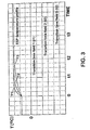
- Figure 3 schematically illustrates how the temperature in the three sections vary with time when the gas temperature is increased. It also appears how transitional adjustments of different durations t1,t2,t3 for the three sections may advantageously be carried out in the transition period, the durations corresponding substantially to the existing temperature profile for the relevant section.
- the temperature in the section which is the first encountered in the flow path of the gas is the first to reach the increased value
- the section which is the last encountered in the flow path of the gas is the last to reach the increased value.
- the gas temperature is regulated by injection of water and the following is carried out in the first section: the frequencies of the back-corona measurements are adapted to the temperature profile, current reduction following spark is carried out in accordance with the actual current of the precipitator, and the re-regulation rate for the current is constantly maintained at a high value.
- spark frequency may increase when the current reduction of the current decreases as a consequence of a reduced current intensity.
- optimum efficiency of the precipitator is obtained.
- a corresponding regulation of the second and third precipitator section is carried out.
- a corresponding regulation is carried out during the transition period, in which case the transition period will have an increased duration.
Landscapes
- Engineering & Computer Science (AREA)
- Chemical & Material Sciences (AREA)
- Ceramic Engineering (AREA)
- Organic Chemistry (AREA)
- General Engineering & Computer Science (AREA)
- Materials Engineering (AREA)
- Structural Engineering (AREA)
- Mechanical Engineering (AREA)
- Thermal Sciences (AREA)
- Physics & Mathematics (AREA)
- Electrostatic Separation (AREA)
- Waste-Gas Treatment And Other Accessory Devices For Furnaces (AREA)
- Manufacture And Refinement Of Metals (AREA)
- Curing Cements, Concrete, And Artificial Stone (AREA)
- Drying Of Solid Materials (AREA)
Description
- the flow in the individual section which is regulated by means of the current limit and the so-called degree of intermittence,
- the re-regulation rate of the current following a spark, and
- the spark frequency.
Claims (5)
- A method for regulating the flue gas temperature in a cement production plant comprising a kiln, a flue gas conditioning device, a mill, and an electrostatic precipitator, whereby the flue gas from the kiln is passed through the conditioning device and is from there conveyed either via the mill or directly to the electrostatic precipitator, whereby a measurement of the flue gas temperature is carried out in the flow path of the gas before the electrostatic precipitator, and whereby water is supplied to the flue gas for cooling purposes in the conditioning device as a response to this temperature measurement if the temperature is too elevated, characterized in that a measurement of the flue gas temperature is carried out prior to its introduction into the conditioning device, that a flow measurement of the flue gas is carried out, and that, on the basis of this temperature measurement and flow measurement, a required water amount is defined for cooling the flue gas to a desired temperature and that this amount of water is supplied to the flue gas.
- A method according to claim 1, characterized in that in cases where the electrostatic precipitator comprises a plurality of precipitator sections, and where a temperature increase occurs in the transition period, a separate control of each precipitator section is carried out in the transition period.
- A method according to claim 2, characterized in that the controls performed in the transition period have different durations for the respective precipitator sections, said durations increasing in the flow direction of the gas.
- A cement production plant, comprising:characterized in that the flue gas regulating system comprises:a kiln having a flue gas outlet connected to a flue gas inlet of a conditioning device having a flue gas outlet connected to a flue gas inlet of an electrostatic precipitator, either via a mill or directly;means for supplying water to the flue gas for cooling purposes in the conditioning device as a response to a measurement of the temperature of the flue gas before the flue gas inlet of the electrostatic precipitator if the temperature is too elevated; anda flue gas regulating system,a sub-system, operating when the mill is not in operation, which regulates the amount of the supplied water by:measuring the temperature (Tl) and the flow (Vg) of the flue gas prior to its introduction into the conditioning device, andcalculating the amount of water required for cooling the flue gas to a desired temperature on the basis of the measured values of Tl and Vg.
- A cement production plant according to claim 4, comprising:characterized in that the flue gas regulating system comprises:a kiln having a flue gas outlet connected to a flue gas inlet of a conditioning device having a flue gas outlet connected to a flue gas inlet of an electrostatic precipitator, either via a mill or directly;means for supplying water to the flue gas for cooling purposes in the conditioning device as a response to a measurement of the temperature of the flue gas before the flue gas inlet of the electrostatic precipitator if the temperature is too elevated; anda flue gas regulating system,i. a first system, operating during the operation of the mill, which regulates the amount of the supplied water in accordance with a measurement of the temperature of the flue gas between the flue gas outlet of the conditioning device and the flue gas inlet of the electrostatic precipitator, andii. a second system, operating when the mill is not in operation, which regulates the amount of the supplied water by:measuring the temperature (Tl) and the flow (Vg) of the flue gas prior to its introduction into the conditioning device, andcalculating the amount of water required for cooling the flue gas to a desired temperature on the basis of the measured values of Tl and Vg, andiii. an automatic switch for alternating between the first system and the second system dependent on whether the mill is in operation or not.
Applications Claiming Priority (3)
| Application Number | Priority Date | Filing Date | Title |
|---|---|---|---|
| DK67996 | 1996-06-18 | ||
| DK067996A DK67996A (en) | 1996-06-18 | 1996-06-18 | Process for regulating flue gas temperature and voltage supply in an electrofilter for a cement production plant |
| PCT/DK1997/000262 WO1997048652A1 (en) | 1996-06-18 | 1997-06-17 | A method of regulating the flue gas temperature and voltage supply in an electrostatic precipitator for a cement production plant |
Publications (2)
| Publication Number | Publication Date |
|---|---|
| EP0906251A1 EP0906251A1 (en) | 1999-04-07 |
| EP0906251B1 true EP0906251B1 (en) | 2002-09-25 |
Family
ID=8096303
Family Applications (1)
| Application Number | Title | Priority Date | Filing Date |
|---|---|---|---|
| EP97927014A Revoked EP0906251B1 (en) | 1996-06-18 | 1997-06-17 | A method of regulating the flue gas temperature and voltage supply in an electrostatic precipitator for a cement production plant |
Country Status (15)
| Country | Link |
|---|---|
| US (1) | US6293787B1 (en) |
| EP (1) | EP0906251B1 (en) |
| KR (1) | KR100298611B1 (en) |
| CN (1) | CN1098819C (en) |
| AU (1) | AU3166197A (en) |
| BR (1) | BR9709810A (en) |
| DE (1) | DE69715845D1 (en) |
| DK (1) | DK67996A (en) |
| ID (1) | ID17821A (en) |
| IL (1) | IL127625A0 (en) |
| NO (1) | NO985941D0 (en) |
| PL (1) | PL330533A1 (en) |
| TR (1) | TR199802564T2 (en) |
| TW (1) | TW374840B (en) |
| WO (1) | WO1997048652A1 (en) |
Cited By (1)
| Publication number | Priority date | Publication date | Assignee | Title |
|---|---|---|---|---|
| RU2506510C2 (en) * | 2011-10-27 | 2014-02-10 | Общество с ограниченной ответственностью "Научно-производственное предприятие АНАЛИТСИСТЕМЫ" | Automatic control method of slurry supply process to cement furnace |
Families Citing this family (10)
| Publication number | Priority date | Publication date | Assignee | Title |
|---|---|---|---|---|
| DE880845C (en) * | 1948-03-04 | 1953-05-07 | Waagner Biro Ag | Centrifugal separator group |
| AU5221599A (en) * | 1998-07-24 | 2000-02-14 | Spray Drying Systems, Inc. | Process and apparatus for recovery of acid gases from flue gas |
| US7134610B2 (en) * | 2003-06-25 | 2006-11-14 | Spraying Systems Co. | Method and apparatus for monitoring system integrity in gas conditioning applications |
| US7125007B2 (en) * | 2003-06-25 | 2006-10-24 | Spraying Systems Co. | Method and apparatus for reducing air consumption in gas conditioning applications |
| US20050011281A1 (en) * | 2003-06-25 | 2005-01-20 | Spraying Systems Co. | Method and apparatus for system integrity monitoring in spraying applications with self-cleaning showers |
| US8329125B2 (en) | 2011-04-27 | 2012-12-11 | Primex Process Specialists, Inc. | Flue gas recirculation system |
| CN104390472B (en) * | 2014-09-26 | 2016-06-08 | 上海激光电源设备有限责任公司 | Low temperature exhaust heat boiler is adopted to carry out hardening and tempering method and the modifying device of electric precipitation flue gas |
| CN107045314A (en) * | 2017-05-12 | 2017-08-15 | 芜湖乐佳自动化机械有限公司 | A kind of high-low pressure transformation cabinet dedusting control system adjusted based on the time and method |
| CN112904909B (en) * | 2021-01-15 | 2022-02-15 | 深圳市志成金科技有限公司 | Multichannel temperature control box with thing networking communication function |
| CN113578529B (en) * | 2021-09-30 | 2022-02-18 | 苏州浪潮智能科技有限公司 | Server dust removal method and system and related components |
Family Cites Families (5)
| Publication number | Priority date | Publication date | Assignee | Title |
|---|---|---|---|---|
| US3842615A (en) * | 1972-11-06 | 1974-10-22 | Standard Havens | Evaporative cooler |
| DE2724372C2 (en) * | 1977-05-28 | 1986-02-13 | Klöckner-Humboldt-Deutz AG, 5000 Köln | Process for conditioning bypass gases |
| NL8203455A (en) * | 1982-09-03 | 1984-04-02 | Seac Int Bv | METHOD OF CONDITIONING A GAS STREAM LOADED WITH SOLID PARTICLES AND / OR VAPORS |
| GB8431294D0 (en) * | 1984-12-12 | 1985-01-23 | Smidth & Co As F L | Controlling intermittant voltage supply |
| DE4018786A1 (en) * | 1990-06-12 | 1991-12-19 | Krupp Polysius Ag | METHOD FOR PURIFYING THE EXHAUST GASES FROM PLANTS FOR PRODUCING CEMENT CLINKER |
-
1996
- 1996-06-18 DK DK067996A patent/DK67996A/en not_active Application Discontinuation
-
1997
- 1997-06-14 TW TW086108253A patent/TW374840B/en active
- 1997-06-16 ID IDP972059A patent/ID17821A/en unknown
- 1997-06-17 TR TR1998/02564T patent/TR199802564T2/en unknown
- 1997-06-17 IL IL12762597A patent/IL127625A0/en unknown
- 1997-06-17 US US09/214,012 patent/US6293787B1/en not_active Expired - Lifetime
- 1997-06-17 BR BR9709810-8A patent/BR9709810A/en not_active Application Discontinuation
- 1997-06-17 AU AU31661/97A patent/AU3166197A/en not_active Abandoned
- 1997-06-17 KR KR1019980710358A patent/KR100298611B1/en not_active Expired - Fee Related
- 1997-06-17 EP EP97927014A patent/EP0906251B1/en not_active Revoked
- 1997-06-17 CN CN97195645A patent/CN1098819C/en not_active Expired - Fee Related
- 1997-06-17 DE DE69715845T patent/DE69715845D1/en not_active Expired - Lifetime
- 1997-06-17 WO PCT/DK1997/000262 patent/WO1997048652A1/en not_active Ceased
- 1997-06-17 PL PL97330533A patent/PL330533A1/en unknown
-
1998
- 1998-12-17 NO NO985941A patent/NO985941D0/en unknown
Cited By (1)
| Publication number | Priority date | Publication date | Assignee | Title |
|---|---|---|---|---|
| RU2506510C2 (en) * | 2011-10-27 | 2014-02-10 | Общество с ограниченной ответственностью "Научно-производственное предприятие АНАЛИТСИСТЕМЫ" | Automatic control method of slurry supply process to cement furnace |
Also Published As
| Publication number | Publication date |
|---|---|
| KR100298611B1 (en) | 2001-10-29 |
| IL127625A0 (en) | 1999-10-28 |
| NO985941L (en) | 1998-12-17 |
| TW374840B (en) | 1999-11-21 |
| NO985941D0 (en) | 1998-12-17 |
| WO1997048652A1 (en) | 1997-12-24 |
| CN1098819C (en) | 2003-01-15 |
| DK67996A (en) | 1997-12-19 |
| BR9709810A (en) | 2000-01-11 |
| CN1222130A (en) | 1999-07-07 |
| EP0906251A1 (en) | 1999-04-07 |
| DE69715845D1 (en) | 2002-10-31 |
| TR199802564T2 (en) | 2001-01-22 |
| ID17821A (en) | 1998-01-29 |
| AU3166197A (en) | 1998-01-07 |
| KR20000016751A (en) | 2000-03-25 |
| PL330533A1 (en) | 1999-05-24 |
| US6293787B1 (en) | 2001-09-25 |
Similar Documents
| Publication | Publication Date | Title |
|---|---|---|
| US4624685A (en) | Method and apparatus for optimizing power consumption in an electrostatic precipitator | |
| US6293787B1 (en) | Method of regulating the flue gas temperature and voltage supply in an electrostatic precipitator for a cement production plant | |
| CN101334666A (en) | Optimal control method for direct-blown pulverization system of double-inlet and double-outlet steel ball mill | |
| CN105241258A (en) | Segmented multi-target control system and method for circular cooler | |
| CN114895555A (en) | Coal-fired unit furnace coal holographic input environmental protection system optimization method | |
| US4410355A (en) | Process for controlling a pelletizing plant for fine-grained ores | |
| US4471738A (en) | Method and apparatus for minimizing the fuel usage in an internal combustion engine | |
| CN85107416A (en) | Arc furnace burner control Method and equipment | |
| CN108386377A (en) | A kind of remodeling method of dedusting fan end control system and dust pelletizing system | |
| US5784974A (en) | System for improving fuel feed control of volumetric coal feeders | |
| CN112286131A (en) | MAU control system and high-precision control method for MAU of electronic clean workshop | |
| JP2696267B2 (en) | Boiler parallel operation controller | |
| CN116086201A (en) | Secondary combustion injection control system for terminal dust of smelting dust removal system | |
| CN102944108B (en) | Device and method for controlling cooling temperature of high-temperature flue pipe of disc drying equipment | |
| SU1670295A1 (en) | A method of quality control of heat release to consumers involving pronouncedly variable heating load | |
| KR100868440B1 (en) | Flue gas control device for pulverized coal | |
| GB2507004B (en) | Control of blowdown in steam boilers | |
| Hecht et al. | A low cost automatic mill load level control strategy | |
| RU2106411C1 (en) | System of automatic regulation of pressure of blast-furnace gas | |
| SU1546466A1 (en) | Method of automatic control of suction of gas from coke batteries | |
| SU1187883A1 (en) | Automatic control system for grinding and drying in ball mill | |
| CN121089034A (en) | Secondary air PID control strategy of biomass circulating fluidized bed boiler | |
| JPS59138705A (en) | Controller for temperature of supplied water | |
| SU1383071A1 (en) | Method of automatic control of roasting process in fluidized bed furnace | |
| SU1765612A1 (en) | Boilers capacity control method |
Legal Events
| Date | Code | Title | Description |
|---|---|---|---|
| PUAI | Public reference made under article 153(3) epc to a published international application that has entered the european phase |
Free format text: ORIGINAL CODE: 0009012 |
|
| 17P | Request for examination filed |
Effective date: 19981219 |
|
| AK | Designated contracting states |
Kind code of ref document: A1 Designated state(s): DE DK ES FR GB GR IE NL PT SE |
|
| 17Q | First examination report despatched |
Effective date: 19991130 |
|
| GRAG | Despatch of communication of intention to grant |
Free format text: ORIGINAL CODE: EPIDOS AGRA |
|
| GRAG | Despatch of communication of intention to grant |
Free format text: ORIGINAL CODE: EPIDOS AGRA |
|
| GRAH | Despatch of communication of intention to grant a patent |
Free format text: ORIGINAL CODE: EPIDOS IGRA |
|
| GRAH | Despatch of communication of intention to grant a patent |
Free format text: ORIGINAL CODE: EPIDOS IGRA |
|
| GRAA | (expected) grant |
Free format text: ORIGINAL CODE: 0009210 |
|
| AK | Designated contracting states |
Kind code of ref document: B1 Designated state(s): DE DK ES FR GB GR IE NL PT SE |
|
| PG25 | Lapsed in a contracting state [announced via postgrant information from national office to epo] |
Ref country code: NL Free format text: LAPSE BECAUSE OF FAILURE TO SUBMIT A TRANSLATION OF THE DESCRIPTION OR TO PAY THE FEE WITHIN THE PRESCRIBED TIME-LIMIT Effective date: 20020925 Ref country code: GR Free format text: LAPSE BECAUSE OF FAILURE TO SUBMIT A TRANSLATION OF THE DESCRIPTION OR TO PAY THE FEE WITHIN THE PRESCRIBED TIME-LIMIT Effective date: 20020925 Ref country code: FR Free format text: LAPSE BECAUSE OF FAILURE TO SUBMIT A TRANSLATION OF THE DESCRIPTION OR TO PAY THE FEE WITHIN THE PRESCRIBED TIME-LIMIT Effective date: 20020925 |
|
| REG | Reference to a national code |
Ref country code: GB Ref legal event code: FG4D |
|
| REG | Reference to a national code |
Ref country code: IE Ref legal event code: FG4D |
|
| REF | Corresponds to: |
Ref document number: 69715845 Country of ref document: DE Date of ref document: 20021031 |
|
| PG25 | Lapsed in a contracting state [announced via postgrant information from national office to epo] |
Ref country code: SE Free format text: LAPSE BECAUSE OF FAILURE TO SUBMIT A TRANSLATION OF THE DESCRIPTION OR TO PAY THE FEE WITHIN THE PRESCRIBED TIME-LIMIT Effective date: 20021225 Ref country code: DK Free format text: LAPSE BECAUSE OF FAILURE TO SUBMIT A TRANSLATION OF THE DESCRIPTION OR TO PAY THE FEE WITHIN THE PRESCRIBED TIME-LIMIT Effective date: 20021225 |
|
| PG25 | Lapsed in a contracting state [announced via postgrant information from national office to epo] |
Ref country code: PT Free format text: LAPSE BECAUSE OF FAILURE TO SUBMIT A TRANSLATION OF THE DESCRIPTION OR TO PAY THE FEE WITHIN THE PRESCRIBED TIME-LIMIT Effective date: 20021226 |
|
| PG25 | Lapsed in a contracting state [announced via postgrant information from national office to epo] |
Ref country code: DE Free format text: LAPSE BECAUSE OF FAILURE TO SUBMIT A TRANSLATION OF THE DESCRIPTION OR TO PAY THE FEE WITHIN THE PRESCRIBED TIME-LIMIT Effective date: 20021228 |
|
| NLV1 | Nl: lapsed or annulled due to failure to fulfill the requirements of art. 29p and 29m of the patents act | ||
| PG25 | Lapsed in a contracting state [announced via postgrant information from national office to epo] |
Ref country code: ES Free format text: LAPSE BECAUSE OF FAILURE TO SUBMIT A TRANSLATION OF THE DESCRIPTION OR TO PAY THE FEE WITHIN THE PRESCRIBED TIME-LIMIT Effective date: 20030328 |
|
| PG25 | Lapsed in a contracting state [announced via postgrant information from national office to epo] |
Ref country code: IE Free format text: LAPSE BECAUSE OF NON-PAYMENT OF DUE FEES Effective date: 20030617 |
|
| PLBI | Opposition filed |
Free format text: ORIGINAL CODE: 0009260 |
|
| PLBQ | Unpublished change to opponent data |
Free format text: ORIGINAL CODE: EPIDOS OPPO |
|
| EN | Fr: translation not filed | ||
| PLAX | Notice of opposition and request to file observation + time limit sent |
Free format text: ORIGINAL CODE: EPIDOSNOBS2 |
|
| 26 | Opposition filed |
Opponent name: ELEX AG Effective date: 20010623 |
|
| PLAX | Notice of opposition and request to file observation + time limit sent |
Free format text: ORIGINAL CODE: EPIDOSNOBS2 |
|
| PLBB | Reply of patent proprietor to notice(s) of opposition received |
Free format text: ORIGINAL CODE: EPIDOSNOBS3 |
|
| REG | Reference to a national code |
Ref country code: IE Ref legal event code: MM4A |
|
| PGFP | Annual fee paid to national office [announced via postgrant information from national office to epo] |
Ref country code: GB Payment date: 20040616 Year of fee payment: 8 |
|
| PG25 | Lapsed in a contracting state [announced via postgrant information from national office to epo] |
Ref country code: GB Free format text: LAPSE BECAUSE OF NON-PAYMENT OF DUE FEES Effective date: 20050617 |
|
| RDAF | Communication despatched that patent is revoked |
Free format text: ORIGINAL CODE: EPIDOSNREV1 |
|
| GBPC | Gb: european patent ceased through non-payment of renewal fee |
Effective date: 20050617 |
|
| RDAG | Patent revoked |
Free format text: ORIGINAL CODE: 0009271 |
|
| STAA | Information on the status of an ep patent application or granted ep patent |
Free format text: STATUS: PATENT REVOKED |
|
| 27W | Patent revoked |
Effective date: 20051231 |
|
| PLAB | Opposition data, opponent's data or that of the opponent's representative modified |
Free format text: ORIGINAL CODE: 0009299OPPO |