EP0905932B1 - System for receiving, descrambling and reproducing digital broadcast signals - Google Patents
System for receiving, descrambling and reproducing digital broadcast signals Download PDFInfo
- Publication number
- EP0905932B1 EP0905932B1 EP98307884.1A EP98307884A EP0905932B1 EP 0905932 B1 EP0905932 B1 EP 0905932B1 EP 98307884 A EP98307884 A EP 98307884A EP 0905932 B1 EP0905932 B1 EP 0905932B1
- Authority
- EP
- European Patent Office
- Prior art keywords
- data stream
- descrambling
- output
- interface
- descrambler
- Prior art date
- Legal status (The legal status is an assumption and is not a legal conclusion. Google has not performed a legal analysis and makes no representation as to the accuracy of the status listed.)
- Expired - Lifetime
Links
Images


Classifications
-
- H—ELECTRICITY
- H04—ELECTRIC COMMUNICATION TECHNIQUE
- H04N—PICTORIAL COMMUNICATION, e.g. TELEVISION
- H04N21/00—Selective content distribution, e.g. interactive television or video on demand [VOD]
- H04N21/40—Client devices specifically adapted for the reception of or interaction with content, e.g. set-top-box [STB]; Operations thereof
- H04N21/43—Processing of content or additional data, e.g. demultiplexing additional data from a digital video stream; Elementary client operations, e.g. monitoring of home network or synchronising decoder's clock; Client middleware
- H04N21/434—Disassembling of a multiplex stream, e.g. demultiplexing audio and video streams, extraction of additional data from a video stream; Remultiplexing of multiplex streams; Extraction or processing of SI; Disassembling of packetised elementary stream
- H04N21/4347—Demultiplexing of several video streams
-
- H—ELECTRICITY
- H04—ELECTRIC COMMUNICATION TECHNIQUE
- H04H—BROADCAST COMMUNICATION
- H04H60/00—Arrangements for broadcast applications with a direct linking to broadcast information or broadcast space-time; Broadcast-related systems
- H04H60/09—Arrangements for device control with a direct linkage to broadcast information or to broadcast space-time; Arrangements for control of broadcast-related services
- H04H60/14—Arrangements for conditional access to broadcast information or to broadcast-related services
-
- H—ELECTRICITY
- H04—ELECTRIC COMMUNICATION TECHNIQUE
- H04N—PICTORIAL COMMUNICATION, e.g. TELEVISION
- H04N7/00—Television systems
- H04N7/12—Systems in which the television signal is transmitted via one channel or a plurality of parallel channels, the bandwidth of each channel being less than the bandwidth of the television signal
-
- G—PHYSICS
- G06—COMPUTING; CALCULATING OR COUNTING
- G06F—ELECTRIC DIGITAL DATA PROCESSING
- G06F21/00—Security arrangements for protecting computers, components thereof, programs or data against unauthorised activity
- G06F21/60—Protecting data
- G06F21/62—Protecting access to data via a platform, e.g. using keys or access control rules
-
- H—ELECTRICITY
- H04—ELECTRIC COMMUNICATION TECHNIQUE
- H04N—PICTORIAL COMMUNICATION, e.g. TELEVISION
- H04N21/00—Selective content distribution, e.g. interactive television or video on demand [VOD]
- H04N21/20—Servers specifically adapted for the distribution of content, e.g. VOD servers; Operations thereof
- H04N21/21—Server components or server architectures
-
- H—ELECTRICITY
- H04—ELECTRIC COMMUNICATION TECHNIQUE
- H04N—PICTORIAL COMMUNICATION, e.g. TELEVISION
- H04N21/00—Selective content distribution, e.g. interactive television or video on demand [VOD]
- H04N21/20—Servers specifically adapted for the distribution of content, e.g. VOD servers; Operations thereof
- H04N21/23—Processing of content or additional data; Elementary server operations; Server middleware
-
- H—ELECTRICITY
- H04—ELECTRIC COMMUNICATION TECHNIQUE
- H04N—PICTORIAL COMMUNICATION, e.g. TELEVISION
- H04N21/00—Selective content distribution, e.g. interactive television or video on demand [VOD]
- H04N21/40—Client devices specifically adapted for the reception of or interaction with content, e.g. set-top-box [STB]; Operations thereof
- H04N21/41—Structure of client; Structure of client peripherals
- H04N21/414—Specialised client platforms, e.g. receiver in car or embedded in a mobile appliance
- H04N21/4147—PVR [Personal Video Recorder]
-
- H—ELECTRICITY
- H04—ELECTRIC COMMUNICATION TECHNIQUE
- H04N—PICTORIAL COMMUNICATION, e.g. TELEVISION
- H04N21/00—Selective content distribution, e.g. interactive television or video on demand [VOD]
- H04N21/40—Client devices specifically adapted for the reception of or interaction with content, e.g. set-top-box [STB]; Operations thereof
- H04N21/41—Structure of client; Structure of client peripherals
- H04N21/418—External card to be used in combination with the client device, e.g. for conditional access
- H04N21/4184—External card to be used in combination with the client device, e.g. for conditional access providing storage capabilities, e.g. memory stick
-
- H—ELECTRICITY
- H04—ELECTRIC COMMUNICATION TECHNIQUE
- H04N—PICTORIAL COMMUNICATION, e.g. TELEVISION
- H04N21/00—Selective content distribution, e.g. interactive television or video on demand [VOD]
- H04N21/40—Client devices specifically adapted for the reception of or interaction with content, e.g. set-top-box [STB]; Operations thereof
- H04N21/43—Processing of content or additional data, e.g. demultiplexing additional data from a digital video stream; Elementary client operations, e.g. monitoring of home network or synchronising decoder's clock; Client middleware
- H04N21/434—Disassembling of a multiplex stream, e.g. demultiplexing audio and video streams, extraction of additional data from a video stream; Remultiplexing of multiplex streams; Extraction or processing of SI; Disassembling of packetised elementary stream
-
- H—ELECTRICITY
- H04—ELECTRIC COMMUNICATION TECHNIQUE
- H04N—PICTORIAL COMMUNICATION, e.g. TELEVISION
- H04N21/00—Selective content distribution, e.g. interactive television or video on demand [VOD]
- H04N21/40—Client devices specifically adapted for the reception of or interaction with content, e.g. set-top-box [STB]; Operations thereof
- H04N21/43—Processing of content or additional data, e.g. demultiplexing additional data from a digital video stream; Elementary client operations, e.g. monitoring of home network or synchronising decoder's clock; Client middleware
- H04N21/436—Interfacing a local distribution network, e.g. communicating with another STB or one or more peripheral devices inside the home
- H04N21/43607—Interfacing a plurality of external cards, e.g. through a DVB Common Interface [DVB-CI]
-
- H—ELECTRICITY
- H04—ELECTRIC COMMUNICATION TECHNIQUE
- H04N—PICTORIAL COMMUNICATION, e.g. TELEVISION
- H04N21/00—Selective content distribution, e.g. interactive television or video on demand [VOD]
- H04N21/40—Client devices specifically adapted for the reception of or interaction with content, e.g. set-top-box [STB]; Operations thereof
- H04N21/43—Processing of content or additional data, e.g. demultiplexing additional data from a digital video stream; Elementary client operations, e.g. monitoring of home network or synchronising decoder's clock; Client middleware
- H04N21/436—Interfacing a local distribution network, e.g. communicating with another STB or one or more peripheral devices inside the home
- H04N21/43615—Interfacing a Home Network, e.g. for connecting the client to a plurality of peripherals
-
- H—ELECTRICITY
- H04—ELECTRIC COMMUNICATION TECHNIQUE
- H04N—PICTORIAL COMMUNICATION, e.g. TELEVISION
- H04N21/00—Selective content distribution, e.g. interactive television or video on demand [VOD]
- H04N21/40—Client devices specifically adapted for the reception of or interaction with content, e.g. set-top-box [STB]; Operations thereof
- H04N21/43—Processing of content or additional data, e.g. demultiplexing additional data from a digital video stream; Elementary client operations, e.g. monitoring of home network or synchronising decoder's clock; Client middleware
- H04N21/436—Interfacing a local distribution network, e.g. communicating with another STB or one or more peripheral devices inside the home
- H04N21/4363—Adapting the video or multiplex stream to a specific local network, e.g. a IEEE 1394 or Bluetooth® network
- H04N21/43632—Adapting the video or multiplex stream to a specific local network, e.g. a IEEE 1394 or Bluetooth® network involving a wired protocol, e.g. IEEE 1394
-
- H—ELECTRICITY
- H04—ELECTRIC COMMUNICATION TECHNIQUE
- H04N—PICTORIAL COMMUNICATION, e.g. TELEVISION
- H04N21/00—Selective content distribution, e.g. interactive television or video on demand [VOD]
- H04N21/40—Client devices specifically adapted for the reception of or interaction with content, e.g. set-top-box [STB]; Operations thereof
- H04N21/43—Processing of content or additional data, e.g. demultiplexing additional data from a digital video stream; Elementary client operations, e.g. monitoring of home network or synchronising decoder's clock; Client middleware
- H04N21/44—Processing of video elementary streams, e.g. splicing a video clip retrieved from local storage with an incoming video stream, rendering scenes according to MPEG-4 scene graphs
- H04N21/4405—Processing of video elementary streams, e.g. splicing a video clip retrieved from local storage with an incoming video stream, rendering scenes according to MPEG-4 scene graphs involving video stream decryption
-
- H—ELECTRICITY
- H04—ELECTRIC COMMUNICATION TECHNIQUE
- H04N—PICTORIAL COMMUNICATION, e.g. TELEVISION
- H04N21/00—Selective content distribution, e.g. interactive television or video on demand [VOD]
- H04N21/40—Client devices specifically adapted for the reception of or interaction with content, e.g. set-top-box [STB]; Operations thereof
- H04N21/43—Processing of content or additional data, e.g. demultiplexing additional data from a digital video stream; Elementary client operations, e.g. monitoring of home network or synchronising decoder's clock; Client middleware
- H04N21/44—Processing of video elementary streams, e.g. splicing a video clip retrieved from local storage with an incoming video stream, rendering scenes according to MPEG-4 scene graphs
- H04N21/4408—Processing of video elementary streams, e.g. splicing a video clip retrieved from local storage with an incoming video stream, rendering scenes according to MPEG-4 scene graphs involving video stream encryption, e.g. re-encrypting a decrypted video stream for redistribution in a home network
-
- H—ELECTRICITY
- H04—ELECTRIC COMMUNICATION TECHNIQUE
- H04N—PICTORIAL COMMUNICATION, e.g. TELEVISION
- H04N21/00—Selective content distribution, e.g. interactive television or video on demand [VOD]
- H04N21/40—Client devices specifically adapted for the reception of or interaction with content, e.g. set-top-box [STB]; Operations thereof
- H04N21/43—Processing of content or additional data, e.g. demultiplexing additional data from a digital video stream; Elementary client operations, e.g. monitoring of home network or synchronising decoder's clock; Client middleware
- H04N21/442—Monitoring of processes or resources, e.g. detecting the failure of a recording device, monitoring the downstream bandwidth, the number of times a movie has been viewed, the storage space available from the internal hard disk
- H04N21/44204—Monitoring of content usage, e.g. the number of times a movie has been viewed, copied or the amount which has been watched
-
- H—ELECTRICITY
- H04—ELECTRIC COMMUNICATION TECHNIQUE
- H04N—PICTORIAL COMMUNICATION, e.g. TELEVISION
- H04N21/00—Selective content distribution, e.g. interactive television or video on demand [VOD]
- H04N21/40—Client devices specifically adapted for the reception of or interaction with content, e.g. set-top-box [STB]; Operations thereof
- H04N21/45—Management operations performed by the client for facilitating the reception of or the interaction with the content or administrating data related to the end-user or to the client device itself, e.g. learning user preferences for recommending movies, resolving scheduling conflicts
- H04N21/462—Content or additional data management, e.g. creating a master electronic program guide from data received from the Internet and a Head-end, controlling the complexity of a video stream by scaling the resolution or bit-rate based on the client capabilities
- H04N21/4622—Retrieving content or additional data from different sources, e.g. from a broadcast channel and the Internet
-
- H—ELECTRICITY
- H04—ELECTRIC COMMUNICATION TECHNIQUE
- H04N—PICTORIAL COMMUNICATION, e.g. TELEVISION
- H04N21/00—Selective content distribution, e.g. interactive television or video on demand [VOD]
- H04N21/40—Client devices specifically adapted for the reception of or interaction with content, e.g. set-top-box [STB]; Operations thereof
- H04N21/45—Management operations performed by the client for facilitating the reception of or the interaction with the content or administrating data related to the end-user or to the client device itself, e.g. learning user preferences for recommending movies, resolving scheduling conflicts
- H04N21/462—Content or additional data management, e.g. creating a master electronic program guide from data received from the Internet and a Head-end, controlling the complexity of a video stream by scaling the resolution or bit-rate based on the client capabilities
- H04N21/4627—Rights management associated to the content
-
- H—ELECTRICITY
- H04—ELECTRIC COMMUNICATION TECHNIQUE
- H04N—PICTORIAL COMMUNICATION, e.g. TELEVISION
- H04N21/00—Selective content distribution, e.g. interactive television or video on demand [VOD]
- H04N21/60—Network structure or processes for video distribution between server and client or between remote clients; Control signalling between clients, server and network components; Transmission of management data between server and client, e.g. sending from server to client commands for recording incoming content stream; Communication details between server and client
- H04N21/61—Network physical structure; Signal processing
- H04N21/6156—Network physical structure; Signal processing specially adapted to the upstream path of the transmission network
- H04N21/6175—Network physical structure; Signal processing specially adapted to the upstream path of the transmission network involving transmission via Internet
-
- H—ELECTRICITY
- H04—ELECTRIC COMMUNICATION TECHNIQUE
- H04N—PICTORIAL COMMUNICATION, e.g. TELEVISION
- H04N7/00—Television systems
- H04N7/16—Analogue secrecy systems; Analogue subscription systems
- H04N7/167—Systems rendering the television signal unintelligible and subsequently intelligible
- H04N7/1675—Providing digital key or authorisation information for generation or regeneration of the scrambling sequence
-
- H—ELECTRICITY
- H04—ELECTRIC COMMUNICATION TECHNIQUE
- H04H—BROADCAST COMMUNICATION
- H04H60/00—Arrangements for broadcast applications with a direct linking to broadcast information or broadcast space-time; Broadcast-related systems
- H04H60/09—Arrangements for device control with a direct linkage to broadcast information or to broadcast space-time; Arrangements for control of broadcast-related services
- H04H60/14—Arrangements for conditional access to broadcast information or to broadcast-related services
- H04H60/23—Arrangements for conditional access to broadcast information or to broadcast-related services using cryptography, e.g. encryption, authentication, key distribution
Definitions
- the present invention relates to an information processing system which receives a digital broadcast transmitted from a plurality of broadcasting providers and reproduces this digital broadcast.
- Conventional digital broadcast receiving apparatuses respond to only broadcasting signals from a specific broadcasting provider. Therefore, when a broadcast from a plurality of broadcasting providers is to be received, there is a problem in that a plurality of receiving apparatuses are required, and the financial burden on a user is consequently large.
- EP-A-0,784,401 discloses a digital broadcast receiving apparatus in which a selected decoded program may be output through an IEEE1394 channel to a recording device and later replayed through that channel.
- Bloks R.H.J. "The IEEE-1394 high speed serial bus", PHILIPS JOURNAL OF RESEARCH, ELSEVIER, AMSTERDAM, NL, vol. 50, no. 1, 1996, pages 209-216 discloses aspects of the IEEE-1394 bus, which may be used for connecting audio video equipment.
- Fig. 1 is a view showing an example of the construction of an embodiment of an information processing system of the present invention.
- CI-STBs 1-1 and 1-2 receive a broadcasting signal from a broadcasting provider and demodulate it, and then output the demodulated data stream via an IEEE1394 interface.
- the demodulated data stream is subjected to a predetermined process by CI-Modules 2-1 to 2-3, is input to the CI-STBs 1-1 and 1-2 again, whereby the plurality of information contained in the data stream is separated and then the obtained information is reproduced, respectively.
- the CI-Modules 2-1 to 2-3 perform a descrambling process on the data stream output from the CI-STBs 1-1 and 1-2, and output the obtained stream via the IEEE1394 interface.
- each of the CI-Modules 2-1 to 2-3 performs a descrambling process on a data stream from a predetermined broadcasting provider.
- a CI-Storage 3 records a data stream output from the CI-STBs 1-1 and 1-2 or the CI-Modules 2-1 to 2-3.
- Fig. 2 is a block diagram showing a detailed example of the construction of the CI-STB 1 shown in Fig. 1 .
- a tuner 10 receives an RF (radio frequency) signal from a broadcasting provider and extracts a signal of a predetermined frequency.
- a demodulator 11 demodulates the signal of the predetermined frequency extracted by the tuner 10 so as to be converted into a data stream.
- a digital interface 12 which is an interface that complies with the IEEE1394 standard, outputs a data stream demodulated by the demodulator 11 to an external apparatus and inputs a data stream from an external apparatus.
- a demultiplexer 13 separates a plurality of information which form a data stream (a data stream on which a descrambling process has been performed) input from the external apparatus through the digital interface 12, and supplies it to an AV (Audio Video) decoder 14.
- AV Audio Video
- the AV decoder 14 decodes each of the plurality of information separated by the demultiplexer 13. More specifically, the AV decoder 14 decodes, for example, each of the sound information and the image information separated by the demultiplexer 13, and outputs the obtained sound signals and image signals.
- An MPU (Microprocessor Unit) 15 controls each section of the apparatus and performs a predetermined computation process as required.
- Fig. 3 is a block diagram showing a detailed example of the construction of the CI-Modules 2-1 to 2-3 shown in Fig. 1 .
- a digital interface 21 which is an interface that complies with the IEEE1394 standard, inputs a data stream output from the CI-STBs 1-1 and 1-2 and outputs a data stream on which a descrambling process has been performed by a descrambler 22.
- An MPU 23 controls each section of the apparatus, and performs various computations as required.
- Fig. 4 is a block diagram showing a detailed example of the construction of the CI-Storage 3 shown in Fig. 1 .
- a digital interface 31 is an interface that complies with the IEEE1394 standard in the same manner as in the above-described case.
- a storage section 32 formed of a semiconductor memory and a magnetic recording medium, stores a data stream output from the digital interface 31, and reads a stored data stream and outputs it to the digital interface 31, under the control of an MPU 33.
- the MPU 33 controls each section of the apparatus and performs a predetermined computation as required.
- a broadcasting signal (RF signal) from a particular broadcasting provider A is received by the tuner 10 of the CI-STB 1-1.
- the tuner 10 extracts a signal of a predetermined frequency from the broadcasting signal and outputs it to the demodulator 11.
- the demodulator 11 performs a demodulation process on the broadcasting signal of the predetermined frequency extracted by the tuner 10 and outputs the obtained data stream to the digital interface 12.
- the digital interface 12 outputs the data stream supplied from the demodulator 11 as a sequence of packets that comply with the IEEE1394 standard. At this time, the data stream is transmitted in an Isochronous transfer mode suitable for real-time reproduction of images, sound, etc.
- the communications among the MPUs of respective apparatuses through the IEEE1394 are performed by asynchronous transfer.
- the data stream output from the CI-STB 1-1 is supplied, for example, to the CI-Module 2-1.
- the digital interface 21 of the CI-Module 2-1 inputs the data stream output from the CI-STB 1-1 and supplies it to the descrambler 22.
- the descrambler 22 performs a descrambling process on the data stream supplied from the digital interface 21. As a result, the scrambling, which has been performed on the data stream by the broadcasting provider in order to prohibit viewing by someone other than a subscriber, is released.
- the output of the descrambler 22 is supplied to the digital interface 21 again.
- the digital interface 21 outputs the output of the descrambler 22 as a sequence of packets that comply with the IEEE1394 standard.
- the sequence of packets output from the CI-Module 2-1 are received by the CI-STB 1-1 again.
- the digital interface 12 of the CI-STB 1-1 receives the sequence of packets sent from the CI-Module 2-1 and supplies them to the demultiplexer 13.
- the demultiplexer 13 separates a plurality of information contained in the data stream output from the digital interface 12. For example, in the case where this data stream is composed of sound data and image data, the demultiplexer 13 separates it into the sound data and the image data and supplies them to the AV decoder 14.
- the AV decoder 14 decodes the information separated by the demultiplexer 13 and outputs it. For example, in the case where the data stream is composed of sound data and image data, the AV decoder 14 performs a decompression process on each of the sound data and the image data and outputs the obtained sound signals and image signals.
- the CI-Storage 3 records the data stream transmitted between the CI-STB 1-1 and the CI-Module 2-1. More specifically, the MPU 33 receiving a control command instructing that the data stream be recorded controls the digital interface 31 so that the received data stream is supplied to the storage section 32. As a result, the data stream is stored in the storage section 32.
- a broadcasting signal from the broadcasting provider A is received.
- a broadcasting signal from a broadcasting provider B is received and a descrambling process corresponding to the broadcasting provider B is performed by the CI-Module 2-2
- a data stream received by the CI-STB 1-1 is subjected to a descrambling process by the CI-Module 2-2, and then is supplied to the CI-STB 1-1 again, whereby the data stream is decoded into the original sound signals and image signals.
- the CI-Module 2-3 corresponds to a broadcasting provider C
- the CI-STB 1-1 is receiving the broadcast of the broadcasting provider A by using the CI-Module 2-1
- the CI-STB 1-2 is able to receive a broadcast of the broadcasting provider B or the broadcasting provider C by using the CI-Module 2-2 or the CI-Module 2-3.
- the CI-STB 1-1 and the CI-STB 1-2 to receive the data stream which is being output by the CI-Module 2-1 at the same time.
- Fig. 5 is a block diagram showing another example of the construction of the CI-STBs 1-1 and 1-2 shown in Fig. 1 .
- Components in Fig. 5 which correspond to those of Fig. 2 are given the same reference numeral, and accordingly, a description thereof has been omitted.
- a PID (Packet ID) filter 100 is newly added.
- the remaining construction is the same as in the case of Fig. 2 .
- the PID filter 100 extracts only a predetermined program from the data stream output from the demodulator 11 and supplies it to the digital interface 12.
- the PID filter 100 extracts only the packet for the desired program from the transport stream output from the demodulator 11 by referring to a PID (Packet ID of MPEG) and supplies it to the digital interface 12.
- a PID Packet ID of MPEG
- the CI-STBs 1-1 and 1-2 include the PID filter 100, it is possible for the CI-Modules 2-1 to 2-3 to include it. Also, with such a construction, it is possible to reduce the amount of data transmitted over the IEEE1394 bus.
- Figs. 6 and 7 are block diagrams showing another example of the construction of the CI-STBs 1-1 and 1-2 shown in Fig. 1 .
- Components in Figs. 6 and 7 which correspond to those of Fig. 2 are given the same reference numeral, and accordingly, a description thereof has been omitted.
- the CI-STBs 1-1 and 1-2 shown in Fig. 2 are divided into two portions. More specifically, the CI-STBs 1-1 and 1-2 shown in Fig. 2 are divided into the portion ( Fig. 6 : CI-Pre_STB 1a) including the tuner 10 and the demodulator 11 and the portion ( Fig. 7 : CI-Post_STB 1b) including the demultiplexer 13 and the AV decoder 14.
- the respective portions include MPUs 15-1 and 15-2 required for control and digital interfaces 12-1 and 12-2 required for exchanging data.
- the broadcasting signal (RF signal) from the broadcasting provider A received by the tuner 10 is received by the tuner 10 of the CI-Pre_STB 1a.
- the tuner 10 extracts a signal of a predetermined frequency from the broadcasting signal and outputs it to the demodulator 11.
- the demodulator 11 performs a demodulation process on the broadcasting signal of the predetermined frequency extracted by the tuner 10 and outputs the obtained data stream to the digital interface 12-1.
- the digital interface 12-1 outputs the data stream supplied from the demodulator 11 as a sequence of packets that comply with the IEEE1394 standard.
- the data stream output from the digital interface 12-1 is supplied, for example, to the CI-Module 2-1 whereby it is subjected to a descrambling process and is sent out to the IEEE1394 bus again.
- the sequence of packets output from the CI-Module 2-1 are received by the digital interface 12-2 of the CI-Post_STB 1b.
- the digital interface 12-2 receives the sequence of packets sent out from the CI-Module 2-1 and supplies them to the demultiplexer 13.
- the demultiplexer 13 separates a plurality of information contained in the data stream output from the digital interface 12-2 and supplies it to the AV decoder 14.
- the AV decoder 14 decodes the information separated by the demultiplexer 13 and outputs the original image and sound signals.
- Fig. 8 is a block diagram showing another example of the construction of the CI-Post_STB 1b shown in Fig. 7 .
- Components in Fig. 8 which correspond to those of Fig. 7 are given the same reference numeral, and accordingly, a description thereof has been omitted.
- a speaker 111 and a CRT monitor 112 are added.
- the remaining construction is the same as in the case of Fig. 7 .
- the speaker 111 converts a sound signal output from the AV decoder 14 into sound. Also, the CRT monitor 112 displays and outputs image signals output from the AV decoder 14.
- the sequence of packets output from the CI-Module 2-1 are received by the digital interface 12-2 of the CI-Post_STB 1b.
- the digital interface 12-2 receives the sequence of packets sent out from the CI-Module 2-1 and supplies them to the demultiplexer 13.
- the demultiplexer 13 separates a plurality of information contained in the data stream output from the digital interface 12-2 and supplies it to the AV decoder 14.
- the AV decoder 14 decodes the information separated by the demultiplexer 13, and outputs the sound signals to the speaker 111 and outputs the image signals to the CRT monitor 112.
- the image is displayed on the CRT monitor 112, and the corresponding sound is output from the speaker 111.
- the CI-Post_STB 1b, and the speaker 111 and the CRT monitor 112 can be formed into one unit.
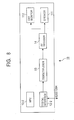
- Fig. 9 is a block diagram showing another example of the construction of the CI-Module 2 shown in Fig. 1 .
- Components in Fig. 9 which correspond to those of Fig. 3 are given the same reference numeral, and accordingly, a description thereof has been omitted.
- a selector 200 is newly added, and also, the descrambler 22 is increased in number to two descramblers 22-1 and 22-2. The remaining construction is the same as in the case shown in Fig. 3 .
- the selector 200 supplies the data stream output from the digital interface 21 to either the descrambler 22-1 or the descrambler 22-2, selects either of the data streams output from the descrambler 22-1 and the descrambler 22-2, and supplies it to the digital interface 21.
- the descrambler 22-1 and the descrambler 22-2 perform, for example, a descrambling process corresponding to the broadcasting provider A and the broadcasting provider B, respectively.
- the descrambler 22-1 corresponds to the broadcasting provider A
- the descrambler 22-2 corresponds to the broadcasting provider B.
- the MPU 23 controls the selector 200 so that it selects the descrambler 22-2.
- the digital interface 21 receives the data stream and outputs it to the selector 200. Since the selector 200 is connected to the descrambler 22-2 as described above, the data stream is subjected to a descrambling process by the descrambler 22-2, and then supplied to the digital interface 21 again through the selector 200.
- the data stream output from the digital interface 21 is reproduced by the CI-STB 1-1.
- the selector 200 selects the descrambler 22-1.
- the CI-Module 2 since the CI-Module 2 includes the descramblers 22-1 and 22-1 corresponding to different broadcasting providers, and the selector 200, so that a desired descrambler is selected by the selector 200 in such a manner as to correspond to the broadcasting provider of a broadcast to be received, it is possible for one CI-Module 2 to receive broadcasts of a plurality of broadcasting providers.
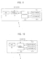
- Fig. 10 is a block diagram showing another example of the construction of the CI-Module 2 shown in Fig. 1 .
- Components in Fig. 10 which correspond to those of Fig. 9 are given the same reference numeral, and accordingly, a description thereof has been omitted.
- the selector 200 has been omitted, and also, the digital interface 21 has been replaced with a digital interface 210.
- the remaining construction is the same as in the case shown in Fig. 9 .
- the descrambler 22-1 corresponds to the broadcasting provider A
- the descrambler 22-2 corresponds to the broadcasting provider B.
- the digital interface 210 receives these data streams and supplies them to the descramblers 22-1 and 22-2, respectively.
- the data streams are subjected to the descrambling process by the descramblers 22-1 and 22-2 and then are sent out through the digital interface 210.
- the data streams corresponding to the broadcasting provider A and the broadcasting provider B output from the digital interface 210 are reproduced simultaneously by the CI-STB 1-1 and the CI-STB 1-2, respectively.
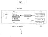
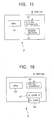
- Fig. 11 is a view showing another example of the construction of the CI-Module 2 shown in Fig. 1 .
- Components in Fig. 11 which correspond to those of Fig. 3 are given the same reference numeral, and accordingly, a description thereof has been omitted.
- an encryptor 220, an IC card IF 221, an IC card 222, and a modem section 223 are newly added. The remaining construction is the same as in the case of Fig. 3 .
- the encryptor 220 encrypts a data stream output from the descrambler 22.
- the IC (Integrated Circuit) card IF (Interface) 221 writes predetermined information into the IC card 222 and reads predetermined information stored in the IC card 222.
- the IC card 222 can be inserted into and removed from the IC card IF 221.
- the modem section 223 is connected to the broadcasting provider side through a public network so that information, such as accounting information, can be exchanged with the provider.
- Fig. 12 is a block diagram showing an example of the construction of the CI-STB 1 corresponding to the CI-Module 2 of Fig. 11 .
- Components in Fig. 12 which correspond to those of Fig. 2 are given the same reference numeral, and accordingly, a description thereof has been omitted.
- a decryptor 120 is newly added.
- the remaining construction is the same as in the case of Fig. 2 .
- the decryptor 120 decodes the data stream encrypted by the encryptor 220 of Fig. 11 into the original data stream.
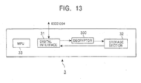
- Fig. 13 is a block diagram showing an example of the construction of the CI-Storage 3 corresponding to that of Fig. 11 .
- Components in Fig. 13 which correspond to those of Fig. 4 are given the same reference numeral, and accordingly, a description thereof has been omitted.
- a decryptor 300 is newly added.
- the remaining construction is the same as in the case of Fig. 4 .
- Fig. 14 is a flowchart illustrating an example of the process performed in the embodiment of Figs. 11 to 13 .
- the MPU 23 obtains a viewing program. More specifically, when the system is powered on and a desired program is selected by the user, the MPU 23 obtains a packet which is contained in the data stream output from the digital interface 21 and which contains information for the selected program.
- step S2 the accounting information is obtained. More specifically, the MPU 23 obtains the accounting information of the program which is viewed currently by referring to the packet containing the accounting information from among the packets obtained in step S1. The process then proceeds to step S3.
- step S3 limitation information is obtained. More specifically, the MPU 23 obtains information, such as the limitation number of the output apparatuses, by referring to the limitation information in the packet containing the accounting information referred to in step S2.
- step S4 the MPU 23 detects the number of apparatuses as the objects of output of data stream output from the descrambler 22 and compares it with the limitation information obtained in step S3, thereby determining whether or not the number of output apparatuses is greater than the limitation number (step 5).
- the output apparatuses corresponding to the limitation number from among the output apparatuses as the objects of output are determined (step 6). For example, the output apparatus selected earlier is given priority in the sequence in which the user specified as an output apparatus.
- the data encrypted by the encryptor 220 is transmitted to only output apparatuses within the limitation number, selected in this manner, in isochronous communication, and information for decoding the encrypted data is transmitted in asynchronous communication of IEEE1394 (step 7).
- Limitation of the number of apparatuses as the objects of output may be performed for each type of apparatus, for example, in such a manner that N is a limitation number for model A and M is a limitation number for model B.
- step S5 when it is determined that the number of output apparatuses is smaller (NO) than the limitation number, the process proceeds to step S7 where the data encrypted by the encryptor 220 is transmitted in the isochronous communication to only the selected output apparatuses within the limitation number, and information for decoding the encrypted data is transmitted in the asynchronous communication of IEEE1394 (step 7).
- step S8 the MPU 23 computes the account charge.
- the MPU 23 computes the sum of the product of the number of CI-Modules 2 which are the output destinations at present and the account charge f 1 per CI-Module 2, and the product of the number of CI-Storages 3 which are the output destinations and the account charge f 2 per CI-Storage 3.
- the computed value is supplied as the account charge to the IC card 222 in which it is stored therein in step S9. Then, the process is terminated (END).
- the number of apparatuses for the objects of output can be smaller than the limitation number, and accounting can be performed according to the type of output apparatus and the number thereof. Therefore, on the broadcasting provider side, it is possible to limit, as required, the use of an apparatus on the user side. Furthermore, for example, by setting the account charge f 2 in the case where the information is stored in the CI-Storage 3 higher than the account charge f 1 in the case where information is viewed by the CI-Module 2, it is possible to perform accounting which is appropriate to the use of the information and to the number of output apparatuses.
- the account charge stored in the IC card 222 can be transmitted to the broadcasting provider side through the modem section 223, for example, at an incidence of once per day, and the account charge of each user can be computed.
- a certain function block of the CI-Module 2 is, for example, formed as an independent block so that it can be used by another CI-Module 2, thereby making it possible to simplify the construction of the CI-Module 2.
- Figs. 15 and 16 show block diagrams of a case in which a function block which can be shared among different broadcasting providers is formed as an independent block.
- Fig. 15 shows an example of the construction of a CI-Modem 4 in which only a modem section 41 is an independent block.
- This embodiment comprises a digital interface 40, a modem section 41, and an MPU 42.
- Fig. 16 shows an example of the construction of a CI-Card 5 in which only the IC card is formed as an independent block.
- This embodiment comprises a digital interface 50, an IC card IF 51, an IC card 52, and an MPU 53.
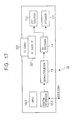
- Fig. 17 is a view showing an example of the construction of the CI-Post_STB 1b. Components in Fig. 17 which correspond to those of Fig. 7 are given the same reference numeral, and accordingly, a description thereof has been omitted.
- an IC card IF 221, an IC card 222, a speaker 111, and a CRT monitor 112 are newly added.
- Each block is the same as in the above-described case, and accordingly, a description thereof has been omitted.
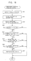
- Fig. 18 is a flowchart illustrating an example of a process performed in the embodiment shown in Fig. 17 .
- step S20 the MPU 15-2 obtains a viewing program. More specifically, when the system is powered on and a desired program is selected by the user, the MPU 15-2 obtains a packet which is contained in the data stream output from the digital interface 12-2 and which contains information for the selected program.
- step S21 accounting information is obtained. More specifically, the MPU 15-2 obtains the accounting information of the program which is viewed currently by referring to the packet containing accounting information from among the packets obtained in step S20. The process then proceeds to step S22.
- step S22 reception limitation information is obtained. More specifically, the MPU 15-2 obtains the reception limitation information from the IC card 222 through the IC card IF 221.
- step S23 the MPU 15-2 determines whether or not the program to be viewed can be viewed. More specifically, the MPU 15-2 refers to the reception limitation information obtained in step S22 in order to determine whether or not the program which is viewed currently is a program in which, for example, a child lock is applied.
- the process is terminated (END). Also, when it is determined that a child lock is not applied (YES: a program which can be viewed), the process proceeds to step S24.
- step S24 the MPU 15-2 reads the viewing history from the IC card 222, computes a total number of program viewing up to the present time, and compares the total number of program viewing with the upper limit of number of receptions contained in the reception limitation information obtained in step S22 in order to determine whether or not the number of program viewing is smaller than the upper limit of the number of receptions.
- NO the number of program viewing is greater than the upper limit of the number of receptions
- END the process is terminated
- the process proceeds to step S25.
- step S25 the MPU 15-2 reads the viewing history from the IC card 222, computes the total program reception fee up to the present time, and compares the total program reception fee with the upper limit of the reception fee contained in the reception limitation information obtained in step S22 in order to determine whether or not the program reception fee is smaller than the upper limit of the reception fee.
- the process is terminated (END). Also, when it is determined that the reception fee is not greater than the upper limit of the reception fee (YES), the process proceeds to step S26.
- step S26 the MPU 15-2 reads the present time from a timer section (not shown), and compares the time with the allowable reception time period contained in the reception limitation information obtained in step S22 in order to determine whether or not the present time is included in the allowable reception time period.
- the process is terminated (END). Also, when it is determined that the present time is in the allowable reception time period (YES), the process proceeds to step S27.
- step S27 the reproduction of the broadcasting program is started.
- this lock in the case where a child lock is applied to the program to be viewed, this lock can be detected to limit the viewing. Not only in a case in which the total number of receptions of programs is greater than the upper limit of the number of receptions preset by a user, but also in a case in which the total reception fee is greater than the upper limit of the reception fee preset by a user, it is possible to limit viewing. Furthermore, in order to prevent a child from viewing a late-night program, also when the present time is not included in the allowable reception time period, viewing can be limited.
- the tuner 10 is handled as a common part irrespective of the broadcasting providers, in a case in which, for example, transmission configurations (for example, a satellite broadcast, a ground-wave program, or a cable broadcast) from broadcasting providers are different, this tuner section 10 cannot be handled as a common part. In such a case, as shown in Fig. 19 , it is preferable that the tuner 10 be included in the CI-Module 2.
- Fig. 19 is a block diagram showing an example of the construction of the CI-Module 2 corresponding to the above-described case.
- Components in Fig. 19 which correspond to those of Fig. 3 are given the same reference numeral, and accordingly, a description thereof has been omitted.
- the RF signal of a predetermined frequency extracted by the tuner 10 is demodulated by the demodulator 11 and output in the form of a data stream.
- the descrambler 22 performs a descrambling process on the data stream obtained as a result of demodulation and outputs the obtained data stream through the digital interface 21.
- the data stream output through the digital interface 21 is input, for example, to the CI-Post_STB 1b shown in Fig. 7 , whereby a reproduction process is performed, and the image signals and the sound signals are output.
- the function blocks can be shared, and accordingly, the cost of the apparatus can be reduced.
- a CI-STB'and a CI-Module are used in combination in order to receive a broadcast, in a case in which reception is possible even if processing is not performed by the CI-Module, it is preferable that processing be performed by only the CI-STB.
- the digital interface 12 may output the output of the demodulator 11 directly to the demultiplexer 13 without outputting it to the outside. According to such a method, the amount of information transmitted on the IEEE1394 bus can be reduced, thereby allowing exchange of information to be smoothly performed among the other apparatuses.
- the examples of the transmission medium include not only information recording media, such as FDs (floppy disks) or CD-ROMs (compact disc-read-only memories), but also network transmission media, such as the Internet or a digital satellite.
Description
- The present invention relates to an information processing system which receives a digital broadcast transmitted from a plurality of broadcasting providers and reproduces this digital broadcast.
- With the advances in image and sound compression technology, etc., digital broadcasts are being realized.
- Conventional digital broadcast receiving apparatuses respond to only broadcasting signals from a specific broadcasting provider. Therefore, when a broadcast from a plurality of broadcasting providers is to be received, there is a problem in that a plurality of receiving apparatuses are required, and the financial burden on a user is consequently large.
- Also, in order to dispose a receiving apparatus, an appropriate amount of space is required. Therefore, when a broadcast from a plurality of broadcasting providers is to be received, there is also a problem in that the space occupied by the receiving apparatus can not be ignored.
-
EP-A-0,784,401 discloses a digital broadcast receiving apparatus in which a selected decoded program may be output through an IEEE1394 channel to a recording device and later replayed through that channel. - "DVB conditional access", David J Cutts, "Electronics & Communications Journal" February 1997 discloses an external condition access interface for a broadcast receiver.
- "COMMON INTERFACE SPECIFICATION FOR CONDITIONAL ACCESS AND OTHER DIGITAL VIDEO BROADCASTING DECODER APPLICATIONS", EUROPEAN STANDARD EN 50221, February 1997, defines the interface between a host and the scrambling and conditional access applications, which will operate on an external module. In section 4.2 it is disclosed that the baseline specification includes the implementation on a physical interface compatible with the PC Card standard used in the personal computer industry. Other physical implementations are allowed for in the future.
- Bloks R.H.J.: "The IEEE-1394 high speed serial bus", PHILIPS JOURNAL OF RESEARCH, ELSEVIER, AMSTERDAM, NL, vol. 50, no. 1, 1996, pages 209-216 discloses aspects of the IEEE-1394 bus, which may be used for connecting audio video equipment.
- Various aspects of the invention are set out in the accompanying claims.
- Embodiments of the invention will now be described, by way of example only, with reference to the accompanying drawings, in which:
-
Fig. 1 is a block diagram showing an example of the construction of one embodiment of the present invention. -
Fig. 2 is a block diagram showing a detailed example of the construction of a CI-STB 1 shown inFig. 1 . -
Fig. 3 is a block diagram showing a detailed example of the construction of a CI-Module 2 shown inFig. 1 . -
Fig. 4 is a block diagram showing a detailed example of the construction of a CI-Storage 3 shown inFig. 1 . -
Fig. 5 is a block diagram showing another example of the construction of the CI-STB 1. -
Fig. 6 is a block diagram showing an example of the construction of a CI-STB 1a. -
Fig. 7 is a block diagram showing an example of the construction of a CI-Post_STB 1b. -
Fig. 8 is a block diagram showing another example of the construction of the CI-Post_STB 1b. -
Fig. 9 is a block diagram showing another example of the construction of the CI-Module 2 shown inFig. 1 . -
Fig. 10 is a block diagram showing still another example of the construction of the CI-Module 2 shown inFig. 1 . -
Fig. 11 is a block diagram showing yet still another example of the construction of the CI-Module 2 shown inFig. 1 . -
Fig. 12 is a block diagram showing another example of the construction of the CI-STB 1 shown inFig. 1 . -
Fig. 13 is a block diagram showing another example of the construction of the CI-Storage 3 shown inFig. 1 . -
Fig. 14 is a flowchart illustrating an example of the process performed by the CI-Module 2 shown inFig. 11 . -
Fig. 15 is a block diagram showing a detailed example of the construction of a CI-Modem 4. -
Fig. 16 is a block diagram showing a detailed example of the construction of a CI-Card 5. -
Fig. 17 is a block diagram showing another example of the construction of the CI-Post_STB 1b. -
Fig. 18 is a flowchart illustrating an example of a process performed in the embodiment ofFig. 17 . -
Fig. 19 is a block diagram showing another example of the construction of the CI-Module 2 shown inFig. 1 . -
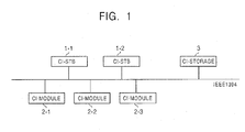
Fig. 1 is a view showing an example of the construction of an embodiment of an information processing system of the present invention. - In this figure, CI-STBs 1-1 and 1-2 receive a broadcasting signal from a broadcasting provider and demodulate it, and then output the demodulated data stream via an IEEE1394 interface. The demodulated data stream is subjected to a predetermined process by CI-Modules 2-1 to 2-3, is input to the CI-STBs 1-1 and 1-2 again, whereby the plurality of information contained in the data stream is separated and then the obtained information is reproduced, respectively.
- The CI-Modules 2-1 to 2-3 perform a descrambling process on the data stream output from the CI-STBs 1-1 and 1-2, and output the obtained stream via the IEEE1394 interface.
- Since this descrambling process is unique to each broadcasting provider, each of the CI-Modules 2-1 to 2-3 performs a descrambling process on a data stream from a predetermined broadcasting provider.
- A CI-
Storage 3 records a data stream output from the CI-STBs 1-1 and 1-2 or the CI-Modules 2-1 to 2-3. -
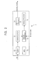
Fig. 2 is a block diagram showing a detailed example of the construction of the CI-STB 1 shown inFig. 1 . - In this figure, a
tuner 10 receives an RF (radio frequency) signal from a broadcasting provider and extracts a signal of a predetermined frequency. Ademodulator 11 demodulates the signal of the predetermined frequency extracted by thetuner 10 so as to be converted into a data stream. - A
digital interface 12, which is an interface that complies with the IEEE1394 standard, outputs a data stream demodulated by thedemodulator 11 to an external apparatus and inputs a data stream from an external apparatus. - A
demultiplexer 13 separates a plurality of information which form a data stream (a data stream on which a descrambling process has been performed) input from the external apparatus through thedigital interface 12, and supplies it to an AV (Audio Video)decoder 14. - The
AV decoder 14 decodes each of the plurality of information separated by thedemultiplexer 13. More specifically, theAV decoder 14 decodes, for example, each of the sound information and the image information separated by thedemultiplexer 13, and outputs the obtained sound signals and image signals. - An MPU (Microprocessor Unit) 15 controls each section of the apparatus and performs a predetermined computation process as required.
-
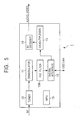
Fig. 3 is a block diagram showing a detailed example of the construction of the CI-Modules 2-1 to 2-3 shown inFig. 1 . - In this figure, a
digital interface 21, which is an interface that complies with the IEEE1394 standard, inputs a data stream output from the CI-STBs 1-1 and 1-2 and outputs a data stream on which a descrambling process has been performed by adescrambler 22. - An
MPU 23 controls each section of the apparatus, and performs various computations as required. -
Fig. 4 is a block diagram showing a detailed example of the construction of the CI-Storage 3 shown inFig. 1 . - In this figure, a
digital interface 31 is an interface that complies with the IEEE1394 standard in the same manner as in the above-described case. - A
storage section 32, formed of a semiconductor memory and a magnetic recording medium, stores a data stream output from thedigital interface 31, and reads a stored data stream and outputs it to thedigital interface 31, under the control of anMPU 33. - The
MPU 33 controls each section of the apparatus and performs a predetermined computation as required. - Next, the operation of the above embodiment is described.
- It is assumed that a broadcasting signal (RF signal) from a particular broadcasting provider A is received by the
tuner 10 of the CI-STB 1-1. Thetuner 10 extracts a signal of a predetermined frequency from the broadcasting signal and outputs it to thedemodulator 11. - The
demodulator 11 performs a demodulation process on the broadcasting signal of the predetermined frequency extracted by thetuner 10 and outputs the obtained data stream to thedigital interface 12. - The
digital interface 12 outputs the data stream supplied from thedemodulator 11 as a sequence of packets that comply with the IEEE1394 standard. At this time, the data stream is transmitted in an Isochronous transfer mode suitable for real-time reproduction of images, sound, etc. - The communications among the MPUs of respective apparatuses through the IEEE1394 are performed by asynchronous transfer.
- The data stream output from the CI-STB 1-1 is supplied, for example, to the CI-Module 2-1.
- The
digital interface 21 of the CI-Module 2-1 inputs the data stream output from the CI-STB 1-1 and supplies it to thedescrambler 22. Thedescrambler 22 performs a descrambling process on the data stream supplied from thedigital interface 21. As a result, the scrambling, which has been performed on the data stream by the broadcasting provider in order to prohibit viewing by someone other than a subscriber, is released. - The output of the
descrambler 22 is supplied to thedigital interface 21 again. As a result, thedigital interface 21 outputs the output of thedescrambler 22 as a sequence of packets that comply with the IEEE1394 standard. - The sequence of packets output from the CI-Module 2-1 are received by the CI-STB 1-1 again.
- The
digital interface 12 of the CI-STB 1-1 receives the sequence of packets sent from the CI-Module 2-1 and supplies them to thedemultiplexer 13. - The
demultiplexer 13 separates a plurality of information contained in the data stream output from thedigital interface 12. For example, in the case where this data stream is composed of sound data and image data, thedemultiplexer 13 separates it into the sound data and the image data and supplies them to theAV decoder 14. - The
AV decoder 14 decodes the information separated by thedemultiplexer 13 and outputs it. For example, in the case where the data stream is composed of sound data and image data, theAV decoder 14 performs a decompression process on each of the sound data and the image data and outputs the obtained sound signals and image signals. - In the case where predetermined control information is supplied from the
MPU 15 or theMPU 23 to the CI-Storage 3 through the IEEE1394 interface, the CI-Storage 3 records the data stream transmitted between the CI-STB 1-1 and the CI-Module 2-1. More specifically, theMPU 33 receiving a control command instructing that the data stream be recorded controls thedigital interface 31 so that the received data stream is supplied to thestorage section 32. As a result, the data stream is stored in thestorage section 32. - It is also possible to supply the data stream stored in the
storage section 32 in this manner to the CI-STB 1-1 and the CI-Module 2-1 and to reproduce it. - In the above, a case is described in which a broadcasting signal from the broadcasting provider A is received. In the case where a broadcasting signal from a broadcasting provider B is received and a descrambling process corresponding to the broadcasting provider B is performed by the CI-Module 2-2, for example, a data stream received by the CI-STB 1-1 is subjected to a descrambling process by the CI-Module 2-2, and then is supplied to the CI-STB 1-1 again, whereby the data stream is decoded into the original sound signals and image signals.
- Also, if it is assumed that the CI-Module 2-3 corresponds to a broadcasting provider C, while the CI-STB 1-1 is receiving the broadcast of the broadcasting provider A by using the CI-Module 2-1, the CI-STB 1-2 is able to receive a broadcast of the broadcasting provider B or the broadcasting provider C by using the CI-Module 2-2 or the CI-Module 2-3. Furthermore, it is also possible for the CI-STB 1-1 and the CI-STB 1-2 to receive the data stream which is being output by the CI-Module 2-1 at the same time.
- In the manner described above, since the portions formed of the same components are formed into CI-STBs 1-1 and 1-2 irrespective of the broadcasting provider and the
descrambler 22 requiring a process unique to each broadcasting provider is formed into independent components as CI-Modules 2-1 to 2-3, in a case in which broadcasting signals from a plurality of broadcasting providers are received, a common function block can be shared, making it possible to view many broadcasts at a low cost. -
Fig. 5 is a block diagram showing another example of the construction of the CI-STBs 1-1 and 1-2 shown inFig. 1 . Components inFig. 5 which correspond to those ofFig. 2 are given the same reference numeral, and accordingly, a description thereof has been omitted. - In the embodiment of
Fig. 5 , in comparison with the case ofFig. 2 , a PID (Packet ID)filter 100 is newly added. The remaining construction is the same as in the case ofFig. 2 . - The
PID filter 100 extracts only a predetermined program from the data stream output from thedemodulator 11 and supplies it to thedigital interface 12. - Next, the operation of the above embodiment is described.
- In the case where the sound data and the image data which form the broadcast received by the
tuner 10 has been compressed in accordance with MPEG (Moving Picture Experts Group), there is a case in which a plurality of programs have been multiplexed on one data stream. - In the case where such a broadcasting signal is received, the
PID filter 100 extracts only the packet for the desired program from the transport stream output from thedemodulator 11 by referring to a PID (Packet ID of MPEG) and supplies it to thedigital interface 12. As a result, since only the packet for the desired program is sent out from thedigital interface 12, for example, the amount of processing in the CI-Modules 2-1 to 2-3 is reduced, and in the case where the data stream is stored in the CI-Storage 3, it is possible to reduce the required storage capacity. - Although, in the above embodiment, the CI-STBs 1-1 and 1-2 include the
PID filter 100, it is possible for the CI-Modules 2-1 to 2-3 to include it. Also, with such a construction, it is possible to reduce the amount of data transmitted over the IEEE1394 bus. -
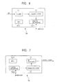
Figs. 6 and 7 are block diagrams showing another example of the construction of the CI-STBs 1-1 and 1-2 shown inFig. 1 . Components inFigs. 6 and 7 which correspond to those ofFig. 2 are given the same reference numeral, and accordingly, a description thereof has been omitted. - In the embodiment of
Figs. 6 and 7 , the CI-STBs 1-1 and 1-2 shown inFig. 2 are divided into two portions. More specifically, the CI-STBs 1-1 and 1-2 shown inFig. 2 are divided into the portion (Fig. 6 : CI-Pre_STB 1a) including thetuner 10 and thedemodulator 11 and the portion (Fig. 7 : CI-Post_STB 1b) including thedemultiplexer 13 and theAV decoder 14. The respective portions include MPUs 15-1 and 15-2 required for control and digital interfaces 12-1 and 12-2 required for exchanging data. - Next, the operation of the above embodiment is described.
- The broadcasting signal (RF signal) from the broadcasting provider A received by the
tuner 10 is received by thetuner 10 of the CI-Pre_STB 1a. Thetuner 10 extracts a signal of a predetermined frequency from the broadcasting signal and outputs it to thedemodulator 11. - The
demodulator 11 performs a demodulation process on the broadcasting signal of the predetermined frequency extracted by thetuner 10 and outputs the obtained data stream to the digital interface 12-1. - The digital interface 12-1 outputs the data stream supplied from the
demodulator 11 as a sequence of packets that comply with the IEEE1394 standard. - The data stream output from the digital interface 12-1 is supplied, for example, to the CI-Module 2-1 whereby it is subjected to a descrambling process and is sent out to the IEEE1394 bus again.
- The sequence of packets output from the CI-Module 2-1 are received by the digital interface 12-2 of the CI-
Post_STB 1b. The digital interface 12-2 receives the sequence of packets sent out from the CI-Module 2-1 and supplies them to thedemultiplexer 13. - The
demultiplexer 13 separates a plurality of information contained in the data stream output from the digital interface 12-2 and supplies it to theAV decoder 14. TheAV decoder 14 decodes the information separated by thedemultiplexer 13 and outputs the original image and sound signals. - According to the above embodiment, in the case where a CI-STB is added, only the portion having the required functions can be added, and therefore, an unwanted expense can be prevented.
-
Fig. 8 is a block diagram showing another example of the construction of the CI-Post_STB 1b shown inFig. 7 . Components inFig. 8 which correspond to those ofFig. 7 are given the same reference numeral, and accordingly, a description thereof has been omitted. - In the embodiment of
Fig. 8 , in comparison with the case ofFig. 7 , aspeaker 111 and aCRT monitor 112 are added. The remaining construction is the same as in the case ofFig. 7 . - The
speaker 111 converts a sound signal output from theAV decoder 14 into sound. Also, the CRT monitor 112 displays and outputs image signals output from theAV decoder 14. - Next, the above embodiment is briefly described.
- For example, the sequence of packets output from the CI-Module 2-1 are received by the digital interface 12-2 of the CI-
Post_STB 1b. The digital interface 12-2 receives the sequence of packets sent out from the CI-Module 2-1 and supplies them to thedemultiplexer 13. - The
demultiplexer 13 separates a plurality of information contained in the data stream output from the digital interface 12-2 and supplies it to theAV decoder 14. TheAV decoder 14 decodes the information separated by thedemultiplexer 13, and outputs the sound signals to thespeaker 111 and outputs the image signals to theCRT monitor 112. - As a result, the image is displayed on the CRT monitor 112, and the corresponding sound is output from the
speaker 111. - According to such an embodiment, the CI-
Post_STB 1b, and thespeaker 111 and the CRT monitor 112 can be formed into one unit. - Next, referring to
Fig. 9 , another example of the construction of the CI-Module 2 is described. -
Fig. 9 is a block diagram showing another example of the construction of the CI-Module 2 shown inFig. 1 . Components inFig. 9 which correspond to those ofFig. 3 are given the same reference numeral, and accordingly, a description thereof has been omitted. In this embodiment, aselector 200 is newly added, and also, thedescrambler 22 is increased in number to two descramblers 22-1 and 22-2. The remaining construction is the same as in the case shown inFig. 3 . - The
selector 200 supplies the data stream output from thedigital interface 21 to either the descrambler 22-1 or the descrambler 22-2, selects either of the data streams output from the descrambler 22-1 and the descrambler 22-2, and supplies it to thedigital interface 21. - The descrambler 22-1 and the descrambler 22-2 perform, for example, a descrambling process corresponding to the broadcasting provider A and the broadcasting provider B, respectively.
- Next, the operation of the above embodiment is described.
- For example, it is assumed that the descrambler 22-1 corresponds to the broadcasting provider A, and the descrambler 22-2 corresponds to the broadcasting provider B. In such a case, in the case where, for example, a broadcast from the broadcasting provider B is received, the
MPU 23 controls theselector 200 so that it selects the descrambler 22-2. - Then, when the data stream corresponding to the broadcasting provider B is output from the CI-STB 1-1, the
digital interface 21 receives the data stream and outputs it to theselector 200. Since theselector 200 is connected to the descrambler 22-2 as described above, the data stream is subjected to a descrambling process by the descrambler 22-2, and then supplied to thedigital interface 21 again through theselector 200. - The data stream output from the
digital interface 21 is reproduced by the CI-STB 1-1. - In the case where a broadcast corresponding to the' broadcasting provider A is received, the
selector 200 selects the descrambler 22-1. - According to the above embodiment, since the CI-
Module 2 includes the descramblers 22-1 and 22-1 corresponding to different broadcasting providers, and theselector 200, so that a desired descrambler is selected by theselector 200 in such a manner as to correspond to the broadcasting provider of a broadcast to be received, it is possible for one CI-Module 2 to receive broadcasts of a plurality of broadcasting providers. - Next, referring to
Fig. 10 , another example of the construction of the CI-Module 2 is described. -
Fig. 10 is a block diagram showing another example of the construction of the CI-Module 2 shown inFig. 1 . Components inFig. 10 which correspond to those ofFig. 9 are given the same reference numeral, and accordingly, a description thereof has been omitted. In this embodiment, in comparison with the case ofFig. 9 , theselector 200 has been omitted, and also, thedigital interface 21 has been replaced with adigital interface 210. The remaining construction is the same as in the case shown inFig. 9 . - Next, the operation of the above embodiment is briefly described.
- In the embodiment shown in
Fig. 10 , it is possible for the descrambler 22-1 and the descrambler 22-2 to perform a descrambling process simultaneously on the data streams from two types of broadcasting providers. Therefore, in the case ofFig. 10 , it is possible to receive broadcasts from two broadcasting providers at the same time. - Next, the above embodiment is briefly described.
- For example, it is assumed that the descrambler 22-1 corresponds to the broadcasting provider A, and the descrambler 22-2 corresponds to the broadcasting provider B.
- Then, when the data stream corresponding to each of the broadcasting providers A and B is output from the CI-STB 1-1 and the CI-STB 1-2, respectively, the
digital interface 210 receives these data streams and supplies them to the descramblers 22-1 and 22-2, respectively. As a result, the data streams are subjected to the descrambling process by the descramblers 22-1 and 22-2 and then are sent out through thedigital interface 210. - The data streams corresponding to the broadcasting provider A and the broadcasting provider B output from the
digital interface 210 are reproduced simultaneously by the CI-STB 1-1 and the CI-STB 1-2, respectively. - According to the above embodiment, it is possible for one apparatus to reproduce a plurality of broadcasts at the same time.
-
Fig. 11 is a view showing another example of the construction of the CI-Module 2 shown inFig. 1 . Components inFig. 11 which correspond to those ofFig. 3 are given the same reference numeral, and accordingly, a description thereof has been omitted. In the embodiment ofFig. 11 , in comparison with the case ofFig. 3 , anencryptor 220, an IC card IF 221, anIC card 222, and amodem section 223 are newly added. The remaining construction is the same as in the case ofFig. 3 . - The
encryptor 220 encrypts a data stream output from thedescrambler 22. - The IC (Integrated Circuit) card IF (Interface) 221 writes predetermined information into the
IC card 222 and reads predetermined information stored in theIC card 222. TheIC card 222 can be inserted into and removed from the IC card IF 221. - The
modem section 223 is connected to the broadcasting provider side through a public network so that information, such as accounting information, can be exchanged with the provider. -
Fig. 12 is a block diagram showing an example of the construction of the CI-STB 1 corresponding to the CI-Module 2 ofFig. 11 . Components inFig. 12 which correspond to those ofFig. 2 are given the same reference numeral, and accordingly, a description thereof has been omitted. - In the embodiment shown in
Fig. 12 , in comparison with the case ofFig. 2 , adecryptor 120 is newly added. The remaining construction is the same as in the case ofFig. 2 . - The
decryptor 120 decodes the data stream encrypted by theencryptor 220 ofFig. 11 into the original data stream. - Therefore, the data stream output from the CI-
Module 2 shown inFig. 11 cannot be reproduced if the CI-STB 1 shown inFig. 12 is not used. Therefore, according to such a technique as above, only the duly authorized apparatus can reproduce information. -
Fig. 13 is a block diagram showing an example of the construction of the CI-Storage 3 corresponding to that ofFig. 11 . Components inFig. 13 which correspond to those ofFig. 4 are given the same reference numeral, and accordingly, a description thereof has been omitted. - In this embodiment, a
decryptor 300 is newly added. The remaining construction is the same as in the case ofFig. 4 . - According to such a construction, since it is possible to decode the data stream encrypted by the
encryptor 220 of the CI-Module 2 ofFig. 11 and to store the decoded data stream in thestorage section 32, only the duly authorized CI-Storage 3 can store the data stream. - There is a case in which for the protection of the copyright of information transmitted through the IEEE1394 interface, an encryption function and a decoding function are provided within the digital interface. In that case, there is no need to provide the above-described
encryptor 220 and decryptors 120 and 300. - Next, referring to
Fig. 14 , the operation of the above embodiment is described. -
Fig. 14 is a flowchart illustrating an example of the process performed in the embodiment ofFigs. 11 to 13 . When this process is performed, in step S1, theMPU 23 obtains a viewing program. More specifically, when the system is powered on and a desired program is selected by the user, theMPU 23 obtains a packet which is contained in the data stream output from thedigital interface 21 and which contains information for the selected program. - In the subsequent step S2, the accounting information is obtained. More specifically, the
MPU 23 obtains the accounting information of the program which is viewed currently by referring to the packet containing the accounting information from among the packets obtained in step S1. The process then proceeds to step S3. - In step S3, limitation information is obtained. More specifically, the
MPU 23 obtains information, such as the limitation number of the output apparatuses, by referring to the limitation information in the packet containing the accounting information referred to in step S2. - In step S4, the
MPU 23 detects the number of apparatuses as the objects of output of data stream output from thedescrambler 22 and compares it with the limitation information obtained in step S3, thereby determining whether or not the number of output apparatuses is greater than the limitation number (step 5). When the result shows that the number of output apparatuses is greater (YES) than the limitation number, the output apparatuses corresponding to the limitation number from among the output apparatuses as the objects of output are determined (step 6). For example, the output apparatus selected earlier is given priority in the sequence in which the user specified as an output apparatus. The data encrypted by theencryptor 220 is transmitted to only output apparatuses within the limitation number, selected in this manner, in isochronous communication, and information for decoding the encrypted data is transmitted in asynchronous communication of IEEE1394 (step 7). - Limitation of the number of apparatuses as the objects of output may be performed for each type of apparatus, for example, in such a manner that N is a limitation number for model A and M is a limitation number for model B.
- As a result of the comparison in step S5, when it is determined that the number of output apparatuses is smaller (NO) than the limitation number, the process proceeds to step S7 where the data encrypted by the
encryptor 220 is transmitted in the isochronous communication to only the selected output apparatuses within the limitation number, and information for decoding the encrypted data is transmitted in the asynchronous communication of IEEE1394 (step 7). In the subsequent step S8, theMPU 23 computes the account charge. More specifically, theMPU 23 computes the sum of the product of the number of CI-Modules 2 which are the output destinations at present and the account charge f1 per CI-Module 2, and the product of the number of CI-Storages 3 which are the output destinations and the account charge f2 per CI-Storage 3. The computed value is supplied as the account charge to theIC card 222 in which it is stored therein in step S9. Then, the process is terminated (END). - According to the above process, the number of apparatuses for the objects of output can be smaller than the limitation number, and accounting can be performed according to the type of output apparatus and the number thereof. Therefore, on the broadcasting provider side, it is possible to limit, as required, the use of an apparatus on the user side. Furthermore, for example, by setting the account charge f2 in the case where the information is stored in the CI-
Storage 3 higher than the account charge f1 in the case where information is viewed by the CI-Module 2, it is possible to perform accounting which is appropriate to the use of the information and to the number of output apparatuses. - As a result of a process such as the above, the account charge stored in the
IC card 222 can be transmitted to the broadcasting provider side through themodem section 223, for example, at an incidence of once per day, and the account charge of each user can be computed. - Furthermore, according to the above embodiment, it is also possible to limit the number of apparatuses for the objects of output.
- In the
modem section 223 and theIC card 222 which constitute the CI-Module 2 shown inFig. 11 , there are often cases in which the specifications differ from one broadcasting provider to another, the viewing history is stored in different data formats, or the method of payment of the account charge is different. However, in a case where the same function block can be used among different broadcasting providers, a certain function block of the CI-Module 2 is, for example, formed as an independent block so that it can be used by another CI-Module 2, thereby making it possible to simplify the construction of the CI-Module 2. -
Figs. 15 and 16 show block diagrams of a case in which a function block which can be shared among different broadcasting providers is formed as an independent block. -
Fig. 15 shows an example of the construction of a CI-Modem 4 in which only amodem section 41 is an independent block. This embodiment comprises adigital interface 40, amodem section 41, and anMPU 42. -
Fig. 16 shows an example of the construction of a CI-Card 5 in which only the IC card is formed as an independent block. This embodiment comprises adigital interface 50, an IC card IF 51, anIC card 52, and anMPU 53. - Each block of the above embodiment is the same as in the above-described case, and accordingly, a description thereof has been omitted.
- In the manner described above, since a function block which can be shared among a plurality of broadcasting providers is an independent component, it is possible to reduce the cost of the apparatus by an amount corresponding to the shared function blocks.
- In digital broadcasts, there are not a few cases in which a charge must be paid per program (for example, Pay_Per_View). By performing a predetermined limitation on such a program, for example, it is possible to prevent a child from freely viewing a pay program. Next, a description is given of an example of the construction of the CI-
Post_STB 1b which makes such a limitation possible. -
Fig. 17 is a view showing an example of the construction of the CI-Post_STB 1b. Components inFig. 17 which correspond to those ofFig. 7 are given the same reference numeral, and accordingly, a description thereof has been omitted. In this embodiment, in comparison with the case ofFig. 7 , an IC card IF 221, anIC card 222, aspeaker 111, and aCRT monitor 112 are newly added. Each block is the same as in the above-described case, and accordingly, a description thereof has been omitted. - Next, referring to
Fig. 18 , the operation of the above embodiment is described. -
Fig. 18 is a flowchart illustrating an example of a process performed in the embodiment shown inFig. 17 . - When this process is performed, in step S20, the MPU 15-2 obtains a viewing program. More specifically, when the system is powered on and a desired program is selected by the user, the MPU 15-2 obtains a packet which is contained in the data stream output from the digital interface 12-2 and which contains information for the selected program.
- In the subsequent step S21, accounting information is obtained. More specifically, the MPU 15-2 obtains the accounting information of the program which is viewed currently by referring to the packet containing accounting information from among the packets obtained in step S20. The process then proceeds to step S22.
- In step S22, reception limitation information is obtained. More specifically, the MPU 15-2 obtains the reception limitation information from the
IC card 222 through the IC card IF 221. - In step S23, the MPU 15-2 determines whether or not the program to be viewed can be viewed. More specifically, the MPU 15-2 refers to the reception limitation information obtained in step S22 in order to determine whether or not the program which is viewed currently is a program in which, for example, a child lock is applied. When the result shows that the program to be viewed is such that a child lock is applied (NO: a program which cannot be viewed), the process is terminated (END). Also, when it is determined that a child lock is not applied (YES: a program which can be viewed), the process proceeds to step S24.
- In step S24, the MPU 15-2 reads the viewing history from the
IC card 222, computes a total number of program viewing up to the present time, and compares the total number of program viewing with the upper limit of number of receptions contained in the reception limitation information obtained in step S22 in order to determine whether or not the number of program viewing is smaller than the upper limit of the number of receptions. When the result shows that the number of program viewing is greater than the upper limit of the number of receptions (NO), the process is terminated (END). Also, when it is determined that the number of receptions is not greater than the upper limit of the number of receptions (YES), the process proceeds to step S25. - In step S25, the MPU 15-2 reads the viewing history from the
IC card 222, computes the total program reception fee up to the present time, and compares the total program reception fee with the upper limit of the reception fee contained in the reception limitation information obtained in step S22 in order to determine whether or not the program reception fee is smaller than the upper limit of the reception fee. When the result shows that the program reception fee is greater than the upper limit of the reception fee (NO), the process is terminated (END). Also, when it is determined that the reception fee is not greater than the upper limit of the reception fee (YES), the process proceeds to step S26. - In step S26, the MPU 15-2 reads the present time from a timer section (not shown), and compares the time with the allowable reception time period contained in the reception limitation information obtained in step S22 in order to determine whether or not the present time is included in the allowable reception time period. When the result shows that the present time is not within the allowable reception time period (NO), the process is terminated (END). Also, when it is determined that the present time is in the allowable reception time period (YES), the process proceeds to step S27.
- In step S27, the reproduction of the broadcasting program is started.
- According to a process such as the above, in the case where a child lock is applied to the program to be viewed, this lock can be detected to limit the viewing. Not only in a case in which the total number of receptions of programs is greater than the upper limit of the number of receptions preset by a user, but also in a case in which the total reception fee is greater than the upper limit of the reception fee preset by a user, it is possible to limit viewing. Furthermore, in order to prevent a child from viewing a late-night program, also when the present time is not included in the allowable reception time period, viewing can be limited.
- Although in the above embodiment the
tuner 10 is handled as a common part irrespective of the broadcasting providers, in a case in which, for example, transmission configurations (for example, a satellite broadcast, a ground-wave program, or a cable broadcast) from broadcasting providers are different, thistuner section 10 cannot be handled as a common part. In such a case, as shown inFig. 19 , it is preferable that thetuner 10 be included in the CI-Module 2. -
Fig. 19 is a block diagram showing an example of the construction of the CI-Module 2 corresponding to the above-described case. Components inFig. 19 which correspond to those ofFig. 3 are given the same reference numeral, and accordingly, a description thereof has been omitted. - In the embodiment of
Fig. 19 , in comparison with the case ofFig. 3 , thetuner 10 and thedemodulator 11 are newly added. The remaining construction is the same as in the case ofFig. 3 . - Since the
tuner 10 and thedemodulator 11 are described earlier, a description thereof has been omitted. - Next, the operation of the above embodiment is described.
- The RF signal of a predetermined frequency extracted by the
tuner 10 is demodulated by thedemodulator 11 and output in the form of a data stream. Thedescrambler 22 performs a descrambling process on the data stream obtained as a result of demodulation and outputs the obtained data stream through thedigital interface 21. - The data stream output through the
digital interface 21 is input, for example, to the CI-Post_STB 1b shown inFig. 7 , whereby a reproduction process is performed, and the image signals and the sound signals are output. - According to the above embodiment, when the
tuner 10 is different depending on the broadcasting provider, the function blocks can be shared, and accordingly, the cost of the apparatus can be reduced. - Finally, although in the above embodiment a CI-STB'and a CI-Module are used in combination in order to receive a broadcast, in a case in which reception is possible even if processing is not performed by the CI-Module, it is preferable that processing be performed by only the CI-STB.
- For example, in the case where the CI-STB takes the form shown in
Fig. 2 , when an external apparatus connected to the IEEE1394 bus does not require a data stream of a broadcast, thedigital interface 12 may output the output of thedemodulator 11 directly to thedemultiplexer 13 without outputting it to the outside. According to such a method, the amount of information transmitted on the IEEE1394 bus can be reduced, thereby allowing exchange of information to be smoothly performed among the other apparatuses. - In this specification, the examples of the transmission medium include not only information recording media, such as FDs (floppy disks) or CD-ROMs (compact disc-read-only memories), but also network transmission media, such as the Internet or a digital satellite.
- Many different embodiments of the present invention may be constructed without departing from the scope of the present invention. It should be understood that the present invention is not limited to the specific embodiments described in this specification. To the contrary, the present invention is intended to cover various modifications and equivalent arrangements included within the scope of the invention as hereafter claimed. The scope of the following claims is to be accorded the broadest interpretation so as to encompass all such modifications, equivalent structures and functions.
Claims (10)
- An information processing system comprising:a plurality of descrambling modules (2-1, 2-2, 2-3); anda plurality of broadcast signal receivers (1-1, 1-2) each coupled via an IEEE1394 bus to said plurality of descrambling modules (2-1, 2-2, 2-3) enabling output of data from each of said plurality of broadcast signal receivers to each of said plurality of descrambling modules; whereineach of said broadcast signal receivers (1-1, 1-2) comprises:receiving means (10) for receiving broadcasting signals;selection means (10) for selecting signals of a predetermined channel from said broadcasting signals received by said receiving means;demodulating means (11) for demodulating a predetermined channel selected by said selection means into a data stream composed of a plurality of information;a receiver interface (12) complying with the IEEE1394 standard for outputting said data stream demodulated by said demodulation means to any one of said plurality of descrambling modules (2-1, 2-2, 2-3); andeach of said plurality of descrambling modules (2-1, 2-2, 2-3) comprises:a descrambler interface (21) complying with the IEEE1394 standard for inputting a data stream processed by one of said plurality of broadcast signal receivers (1-1, 1-2);anddescrambling means (22) for descrambling said data stream input by said descrambler interface (21); andwherein said descrambler interface (21) is configured to output said data stream descrambled by said descrambling means to said one of said plurality of broadcast signal receivers (1-1, 1-2); andeach of said broadcast signal receivers further comprises:demultiplexing means (13) for demultiplexing said data stream descrambled by said descrambler means (22) and received from any one of said plurality of descrambling modules through said receiver interface (12); anddecoding means (14) for decoding said demultiplexed data stream from said demultiplexing means (13).
- An information processing system according to claim 1, wherein each of said plurality of broadcast signal receivers further comprises:extraction means (100) for extracting only predetermined information from among the plurality of information contained in said data stream demodulated by said demodulating means,wherein said receiver interface (12) is configured to only output said predetermined information extracted by said extraction means.
- An information processing system according to claim 1, wherein said one of said plurality of broadcast signal receivers (1-1, 1-2) is an image processing apparatus.
- An information processing system according to claim 1, wherein said one of said plurality of broadcast signal receivers (1-1, 1-2) is a sound processing apparatus.
- An information processing system according to claim 1, further comprising one or more storage modules (3) coupled via an IEEE1394 bus to said plurality of broadcast signal receivers (1-1, 1-2) and said plurality of descrambling modules (2-1, 2-2, 2-3) enabling storage of data received from any one of said plurality of broadcast signal receivers or any one of said plurality of descrambling modules, each of said one or more storage modules (3) comprising:a storage interface complying with the IEEE 1394 standard; andrecording means for recording said data received.
- An information processing system according to claim 1, wherein each of said plurality of descrambling modules (2-1, 2-2, 2-3) further comprises:detection means (23) for detecting the type of devices connected to said descrambler interface (21); andlimitation means (23) for limiting an output of said data stream from said descrambler interface (21)in accordance with the detection result of said detection means.
- An information processing system according to claim 1, wherein each of said plurality of descrambling modules (2-1, 2-2, 2-3) further comprises:detection means (23) for detecting the number of devices connected to said descrambler interface (21); andlimitation means (23) for limiting an output of said data stream from said descrambler interface (21)in accordance with the detection result of said detection means.
- An information processing system according to claim 1, wherein each of said plurality of descrambling modules (2-1, 2-2, 2-3) further comprises:detection means (23) for detecting the type of devices connected to said descrambler interface (21); andcomputation means (23) for computing a reception fee in accordance with the detection result of said detection means.
- An information processing system according to claim 1, wherein each of said plurality of descrambling modules (2-1, 2-2, 2-3) further comprises:detection means (23, S4) for detecting the number of devices connected to said descrambler interface (21); andcomputation means (23, S8) for computing a reception fee (F1, F2) in accordance with the detection result of said detection means.
- An information processing system according to claim 1,
wherein each of said plurality of descrambling modules (2-1, 2-2, 2-3) further comprises encryption means (220) for encrypting an output of said descrambling means, and said descrambler interface (21) is configured to output a data stream output from said encryption means and
wherein each of said plurality of broadcast signal receivers (1-1, 1-2) further comprises decryption means (120) for decrypting the encrypted data stream received from one of said plurality of descrambling modules (2-1, 2-2, 2-3).
Priority Applications (7)
| Application Number | Priority Date | Filing Date | Title |
|---|---|---|---|
| EP10175925A EP2256966A3 (en) | 1997-09-30 | 1998-09-29 | Digital television signal receiving system, computer program storage medium and method for operating the said system |
| EP10177583A EP2259459A3 (en) | 1997-09-30 | 1998-09-29 | Receiver for receiving scrambled digital information |
| EP10177582.3A EP2262136B1 (en) | 1997-09-30 | 1998-09-29 | Receiver for receiving scrambled digital information |
| EP10175916A EP2256964A3 (en) | 1997-09-30 | 1998-09-29 | Digital television signal receiver, computer program storage medium and method for operating the said receiver |
| EP20100175911 EP2256963B1 (en) | 1997-09-30 | 1998-09-29 | System for receiving, descrambling and reproducing digital television signals, corresponding method and corresponding computer program storage medium |
| EP10175922A EP2256965A3 (en) | 1997-09-30 | 1998-09-29 | Broadcast signal receiving system, computer program storage medium and method for operating the said system |
| EP06076009.7A EP1734678B1 (en) | 1997-09-30 | 1998-09-29 | Method and apparatus for receiving and processing digital broadcast signals |
Applications Claiming Priority (3)
| Application Number | Priority Date | Filing Date | Title |
|---|---|---|---|
| JP26755297 | 1997-09-30 | ||
| JP267552/97 | 1997-09-30 | ||
| JP26755297 | 1997-09-30 |
Related Child Applications (10)
| Application Number | Title | Priority Date | Filing Date |
|---|---|---|---|
| EP20100175911 Division EP2256963B1 (en) | 1997-09-30 | 1998-09-29 | System for receiving, descrambling and reproducing digital television signals, corresponding method and corresponding computer program storage medium |
| EP20100175911 Division-Into EP2256963B1 (en) | 1997-09-30 | 1998-09-29 | System for receiving, descrambling and reproducing digital television signals, corresponding method and corresponding computer program storage medium |
| EP10175916A Division-Into EP2256964A3 (en) | 1997-09-30 | 1998-09-29 | Digital television signal receiver, computer program storage medium and method for operating the said receiver |
| EP06076009.7A Division-Into EP1734678B1 (en) | 1997-09-30 | 1998-09-29 | Method and apparatus for receiving and processing digital broadcast signals |
| EP06076009.7A Division EP1734678B1 (en) | 1997-09-30 | 1998-09-29 | Method and apparatus for receiving and processing digital broadcast signals |
| EP10177583A Division-Into EP2259459A3 (en) | 1997-09-30 | 1998-09-29 | Receiver for receiving scrambled digital information |
| EP10175925A Division-Into EP2256966A3 (en) | 1997-09-30 | 1998-09-29 | Digital television signal receiving system, computer program storage medium and method for operating the said system |
| EP10177582.3A Division-Into EP2262136B1 (en) | 1997-09-30 | 1998-09-29 | Receiver for receiving scrambled digital information |
| EP10177582.3A Division EP2262136B1 (en) | 1997-09-30 | 1998-09-29 | Receiver for receiving scrambled digital information |
| EP10175922A Division-Into EP2256965A3 (en) | 1997-09-30 | 1998-09-29 | Broadcast signal receiving system, computer program storage medium and method for operating the said system |
Publications (3)
| Publication Number | Publication Date |
|---|---|
| EP0905932A2 EP0905932A2 (en) | 1999-03-31 |
| EP0905932A3 EP0905932A3 (en) | 2004-12-08 |
| EP0905932B1 true EP0905932B1 (en) | 2015-03-25 |
Family
ID=17446408
Family Applications (8)
| Application Number | Title | Priority Date | Filing Date |
|---|---|---|---|
| EP06076009.7A Expired - Lifetime EP1734678B1 (en) | 1997-09-30 | 1998-09-29 | Method and apparatus for receiving and processing digital broadcast signals |
| EP10177583A Withdrawn EP2259459A3 (en) | 1997-09-30 | 1998-09-29 | Receiver for receiving scrambled digital information |
| EP20100175911 Expired - Lifetime EP2256963B1 (en) | 1997-09-30 | 1998-09-29 | System for receiving, descrambling and reproducing digital television signals, corresponding method and corresponding computer program storage medium |
| EP10175925A Ceased EP2256966A3 (en) | 1997-09-30 | 1998-09-29 | Digital television signal receiving system, computer program storage medium and method for operating the said system |
| EP10175916A Withdrawn EP2256964A3 (en) | 1997-09-30 | 1998-09-29 | Digital television signal receiver, computer program storage medium and method for operating the said receiver |
| EP98307884.1A Expired - Lifetime EP0905932B1 (en) | 1997-09-30 | 1998-09-29 | System for receiving, descrambling and reproducing digital broadcast signals |
| EP10177582.3A Expired - Lifetime EP2262136B1 (en) | 1997-09-30 | 1998-09-29 | Receiver for receiving scrambled digital information |
| EP10175922A Withdrawn EP2256965A3 (en) | 1997-09-30 | 1998-09-29 | Broadcast signal receiving system, computer program storage medium and method for operating the said system |
Family Applications Before (5)
| Application Number | Title | Priority Date | Filing Date |
|---|---|---|---|
| EP06076009.7A Expired - Lifetime EP1734678B1 (en) | 1997-09-30 | 1998-09-29 | Method and apparatus for receiving and processing digital broadcast signals |
| EP10177583A Withdrawn EP2259459A3 (en) | 1997-09-30 | 1998-09-29 | Receiver for receiving scrambled digital information |
| EP20100175911 Expired - Lifetime EP2256963B1 (en) | 1997-09-30 | 1998-09-29 | System for receiving, descrambling and reproducing digital television signals, corresponding method and corresponding computer program storage medium |
| EP10175925A Ceased EP2256966A3 (en) | 1997-09-30 | 1998-09-29 | Digital television signal receiving system, computer program storage medium and method for operating the said system |
| EP10175916A Withdrawn EP2256964A3 (en) | 1997-09-30 | 1998-09-29 | Digital television signal receiver, computer program storage medium and method for operating the said receiver |
Family Applications After (2)
| Application Number | Title | Priority Date | Filing Date |
|---|---|---|---|
| EP10177582.3A Expired - Lifetime EP2262136B1 (en) | 1997-09-30 | 1998-09-29 | Receiver for receiving scrambled digital information |
| EP10175922A Withdrawn EP2256965A3 (en) | 1997-09-30 | 1998-09-29 | Broadcast signal receiving system, computer program storage medium and method for operating the said system |
Country Status (5)
| Country | Link |
|---|---|
| US (8) | US6438693B1 (en) |
| EP (8) | EP1734678B1 (en) |
| KR (1) | KR19990030282A (en) |
| CN (2) | CN100375518C (en) |
| MY (1) | MY123163A (en) |
Families Citing this family (23)
| Publication number | Priority date | Publication date | Assignee | Title |
|---|---|---|---|---|
| WO1998048543A1 (en) * | 1997-04-24 | 1998-10-29 | Matsushita Electric Industrial Co., Ltd. | Data transfer method |
| US6438693B1 (en) * | 1997-09-30 | 2002-08-20 | Sony Corporation | Modular broadcast receiver system and memo |
| EP0952733B1 (en) * | 1998-04-24 | 2006-11-02 | Sony United Kingdom Limited | Digital multimedia receiver and network including such receiver with IEEE 1394 serial bus interface |
| TW432840B (en) * | 1998-06-03 | 2001-05-01 | Sony Corp | Communication control method, system, and device |
| KR100624865B1 (en) * | 1999-06-02 | 2006-09-18 | 엘지전자 주식회사 | Video system based on user profile |
| KR100694043B1 (en) * | 2000-05-18 | 2007-03-12 | 삼성전자주식회사 | Audio/Video system and function- extending module therefor |
| JP3983463B2 (en) * | 2000-09-04 | 2007-09-26 | パイオニア株式会社 | Information transmitting apparatus, information transmitting method, information receiving apparatus, information receiving method, information transmission system, information transmission method, and information recording medium |
| DE10119656B4 (en) * | 2001-04-20 | 2010-03-04 | Mascom Gmbh | Decoding module for receivers for receiving digitally encoded radio or television signals |
| US20030001981A1 (en) * | 2001-05-21 | 2003-01-02 | Sony Corporation | Modular digital television architecture |
| CA2480181A1 (en) * | 2002-04-04 | 2003-10-16 | Grass Valley (U.S.), Inc. | Modular broadcast television products |
| IL155416A0 (en) * | 2003-04-13 | 2003-11-23 | Nds Ltd | System for securing access to data streams |
| KR100547810B1 (en) * | 2003-08-27 | 2006-01-31 | 삼성전자주식회사 | Digital multimedia broadcasting receiving device and method capable of playing digital multimedia data |
| US8132215B2 (en) * | 2003-10-27 | 2012-03-06 | Panasonic Corporation | Apparatus for receiving broadcast signal |
| JP5177939B2 (en) * | 2004-11-10 | 2013-04-10 | 株式会社東芝 | Information processing device |
| CN1851797A (en) * | 2005-04-22 | 2006-10-25 | 鸿富锦精密工业(深圳)有限公司 | Signal adapting device |
| KR20070048060A (en) * | 2005-11-03 | 2007-05-08 | 삼성전자주식회사 | Broadcasting signal recording/playing system, broadcasting signal recording/playing apparatus, broadcasting signal tuning apparatus |
| WO2011146039A1 (en) * | 2010-05-17 | 2011-11-24 | Thomson Licensing | Selective display of a tagged list of broadcast programs available through a video recorder or set top box stb |
| KR20120067184A (en) * | 2010-12-15 | 2012-06-25 | 한국전자통신연구원 | Apparatus and method for generating harmfulness map |
| CN102164319A (en) * | 2011-04-08 | 2011-08-24 | 北京数字太和科技有限责任公司 | Method and device for safely transmitting transport stream (TS) |
| CN102742109B (en) * | 2012-03-01 | 2014-03-26 | 华为技术有限公司 | Remote supply system and remote power supply |
| WO2013139696A1 (en) * | 2012-03-19 | 2013-09-26 | Smardtv S.A. | A system and method for networking conditional access functionalities |
| DE102014115967B4 (en) * | 2014-11-03 | 2023-10-12 | Infineon Technologies Ag | Communication devices and methods |
| JP2017103587A (en) * | 2015-12-01 | 2017-06-08 | 富士通株式会社 | Base station device, transmission system and transmission method |
Citations (2)
| Publication number | Priority date | Publication date | Assignee | Title |
|---|---|---|---|---|
| EP0684721A2 (en) * | 1994-05-24 | 1995-11-29 | Sony Corporation | Data bus communication |
| WO1996008912A2 (en) * | 1994-09-09 | 1996-03-21 | Titan Information Systems Corporation | Conditional access system |
Family Cites Families (15)
| Publication number | Priority date | Publication date | Assignee | Title |
|---|---|---|---|---|
| US5557316A (en) * | 1990-09-28 | 1996-09-17 | Ictv, Inc. | System for distributing broadcast television services identically on a first bandwidth portion of a plurality of express trunks and interactive services over a second bandwidth portion of each express trunk on a subscriber demand basis |
| US5138659A (en) * | 1991-05-02 | 1992-08-11 | General Instrument Corporation | Conversion of television signal formats with retention of common control data stream |
| CA2332405C (en) * | 1992-03-26 | 2007-01-23 | Matsushita Electric Industrial Co., Ltd. | Communication system |
| US5477263A (en) * | 1994-05-26 | 1995-12-19 | Bell Atlantic Network Services, Inc. | Method and apparatus for video on demand with fast forward, reverse and channel pause |
| DE69535971D1 (en) * | 1994-07-08 | 2009-08-06 | Sony Corp | Reception of broadcast signals with conditional access |
| MY125706A (en) * | 1994-08-19 | 2006-08-30 | Thomson Consumer Electronics | High speed signal processing smart card |
| US5898695A (en) * | 1995-03-29 | 1999-04-27 | Hitachi, Ltd. | Decoder for compressed and multiplexed video and audio data |
| JPH09116450A (en) * | 1995-10-16 | 1997-05-02 | Sony Corp | Receiver |
| US5899578A (en) | 1995-12-25 | 1999-05-04 | Sony Corporation | Digital signal processor, processing method, digital signal recording/playback device and digital signal playback method |
| JP3305183B2 (en) * | 1996-01-12 | 2002-07-22 | 株式会社東芝 | Digital broadcast receiving terminal |
| TW346571B (en) * | 1996-02-06 | 1998-12-01 | Matsushita Electric Ind Co Ltd | Data reception apparatus, data transmission apparatus, information processing system, data reception method |
| US5959692A (en) * | 1996-08-21 | 1999-09-28 | Sony Corporation | Television-signal processing apparatus and television-signal processing |
| IT1289206B1 (en) * | 1996-09-12 | 1998-09-29 | Sgs Thomson Microelectronics | ADPCM RECOMPRESSION AND DECOMPRESSION METHOD OF A STREAM OF DIGITAL DATA CONSTITUTING A DIGITAL VIDEO SIGNAL AND ESTIMATOR |
| JPH10145188A (en) * | 1996-11-07 | 1998-05-29 | Sony Corp | Reception device |
| US6438693B1 (en) * | 1997-09-30 | 2002-08-20 | Sony Corporation | Modular broadcast receiver system and memo |
-
1998
- 1998-09-28 US US09/162,037 patent/US6438693B1/en not_active Expired - Lifetime
- 1998-09-29 EP EP06076009.7A patent/EP1734678B1/en not_active Expired - Lifetime
- 1998-09-29 EP EP10177583A patent/EP2259459A3/en not_active Withdrawn
- 1998-09-29 EP EP20100175911 patent/EP2256963B1/en not_active Expired - Lifetime
- 1998-09-29 EP EP10175925A patent/EP2256966A3/en not_active Ceased
- 1998-09-29 EP EP10175916A patent/EP2256964A3/en not_active Withdrawn
- 1998-09-29 EP EP98307884.1A patent/EP0905932B1/en not_active Expired - Lifetime
- 1998-09-29 EP EP10177582.3A patent/EP2262136B1/en not_active Expired - Lifetime
- 1998-09-29 EP EP10175922A patent/EP2256965A3/en not_active Withdrawn
- 1998-09-29 MY MYPI98004466A patent/MY123163A/en unknown
- 1998-09-30 KR KR1019980040765A patent/KR19990030282A/en active Search and Examination
- 1998-09-30 CN CNB981245315A patent/CN100375518C/en not_active Expired - Lifetime
- 1998-09-30 CN CNA200810001423XA patent/CN101232336A/en active Pending
-
2002
- 2002-06-12 US US10/170,111 patent/US7254715B2/en not_active Expired - Lifetime
-
2007
- 2007-05-03 US US11/799,773 patent/US7796756B2/en not_active Expired - Fee Related
-
2010
- 2010-06-08 US US12/796,016 patent/US8280050B2/en not_active Expired - Fee Related
- 2010-06-08 US US12/796,037 patent/US8189782B2/en not_active Expired - Fee Related
-
2012
- 2012-09-24 US US13/625,358 patent/US8824675B2/en not_active Expired - Fee Related
-
2014
- 2014-05-22 US US14/284,514 patent/US9237373B2/en not_active Expired - Fee Related
-
2015
- 2015-11-17 US US14/943,199 patent/US20160073157A1/en not_active Abandoned
Patent Citations (2)
| Publication number | Priority date | Publication date | Assignee | Title |
|---|---|---|---|---|
| EP0684721A2 (en) * | 1994-05-24 | 1995-11-29 | Sony Corporation | Data bus communication |
| WO1996008912A2 (en) * | 1994-09-09 | 1996-03-21 | Titan Information Systems Corporation | Conditional access system |
Non-Patent Citations (2)
| Title |
|---|
| "COMMON INTERFACE SPECIFICATION FOR CONDITIONAL ACCESS AND OTHER DIGITAL VIDEO BROADCASTING DECODER APPLICATIONS", EUROPEAN STANDARD EN 50221, no. EN 50221, 1 February 1997 (1997-02-01), pages 1 - 86,01, XP000950003 * |
| BLOKS R H J: "The IEEE-1394 high speed serial bus", PHILIPS JOURNAL OF RESEARCH, ELSEVIER, AMSTERDAM, NL, vol. 50, no. 1, 1 January 1996 (1996-01-01), pages 209 - 216, XP004008212, ISSN: 0165-5817, DOI: 10.1016/0165-5817(96)81310-6 * |
Also Published As
Similar Documents
| Publication | Publication Date | Title |
|---|---|---|
| US9237373B2 (en) | Modular broadcast receiver system and method | |
| JP4394833B2 (en) | Communication network | |
| JP4110588B2 (en) | Data receiving apparatus and receiving method | |
| JP4877421B2 (en) | Reception device, reception method, transmission / reception system, and transmission / reception method | |
| WO2001027731A1 (en) | Enhancing interface to transport streams by pin re-assignment | |
| JP2003515286A (en) | Digital television method and apparatus | |
| JP3912563B2 (en) | Input / output device, input / output method, and receiving device | |
| JPH11168486A (en) | Device and method for processing information and provision method | |
| JP2008118629A (en) | Receiver | |
| JP2005354729A (en) | Transmission apparatus and transmission method |
Legal Events
| Date | Code | Title | Description |
|---|---|---|---|
| PUAI | Public reference made under article 153(3) epc to a published international application that has entered the european phase |
Free format text: ORIGINAL CODE: 0009012 |
|
| AK | Designated contracting states |
Kind code of ref document: A2 Designated state(s): AT BE CH CY DE DK ES FI FR GB GR IE IT LI LU MC NL PT SE |
|
| AX | Request for extension of the european patent |
Free format text: AL;LT;LV;MK;RO;SI |
|
| PUAL | Search report despatched |
Free format text: ORIGINAL CODE: 0009013 |
|
| AK | Designated contracting states |
Kind code of ref document: A3 Designated state(s): AT BE CH CY DE DK ES FI FR GB GR IE IT LI LU MC NL PT SE |
|
| AX | Request for extension of the european patent |
Extension state: AL LT LV MK RO SI |
|
| RIC1 | Information provided on ipc code assigned before grant |
Ipc: 7H 04N 5/00 B Ipc: 7H 04H 1/00 A |
|
| 17P | Request for examination filed |
Effective date: 20050524 |
|
| AKX | Designation fees paid |
Designated state(s): DE FR GB |
|
| RAP1 | Party data changed (applicant data changed or rights of an application transferred) |
Owner name: SONY CORPORATION |
|
| REG | Reference to a national code |
Ref country code: DE Ref legal event code: R079 Ref document number: 69843375 Country of ref document: DE Free format text: PREVIOUS MAIN CLASS: H04H0001000000 Ipc: H04H0060140000 |
|
| GRAP | Despatch of communication of intention to grant a patent |
Free format text: ORIGINAL CODE: EPIDOSNIGR1 |
|
| RIC1 | Information provided on ipc code assigned before grant |
Ipc: H04N 7/167 20110101ALI20140930BHEP Ipc: H04N 21/418 20110101ALI20140930BHEP Ipc: H04N 21/61 20110101ALI20140930BHEP Ipc: H04N 21/442 20110101ALI20140930BHEP Ipc: H04H 60/14 20080101AFI20140930BHEP Ipc: H04N 21/23 20110101ALI20140930BHEP Ipc: H04N 21/434 20110101ALI20140930BHEP Ipc: H04N 21/4405 20110101ALI20140930BHEP Ipc: H04N 21/436 20110101ALI20140930BHEP Ipc: H04N 21/4147 20110101ALI20140930BHEP Ipc: H04N 21/4363 20110101ALI20140930BHEP Ipc: G06F 21/62 20130101ALI20140930BHEP Ipc: H04N 21/40 20110101ALI20140930BHEP Ipc: H04H 60/23 20080101ALN20140930BHEP Ipc: H04N 21/21 20110101ALI20140930BHEP Ipc: H04N 21/4627 20110101ALI20140930BHEP Ipc: H04N 21/4408 20110101ALI20140930BHEP |
|
| RIC1 | Information provided on ipc code assigned before grant |
Ipc: H04N 21/4627 20110101ALI20141003BHEP Ipc: G06F 21/62 20130101ALI20141003BHEP Ipc: H04N 21/418 20110101ALI20141003BHEP Ipc: H04N 7/167 20110101ALI20141003BHEP Ipc: H04N 21/4408 20110101ALI20141003BHEP Ipc: H04N 21/40 20110101ALI20141003BHEP Ipc: H04H 60/14 20080101AFI20141003BHEP Ipc: H04H 60/23 20080101ALN20141003BHEP Ipc: H04N 21/23 20110101ALI20141003BHEP Ipc: H04N 21/4363 20110101ALI20141003BHEP Ipc: H04N 21/442 20110101ALI20141003BHEP Ipc: H04N 21/4147 20110101ALI20141003BHEP Ipc: H04N 21/21 20110101ALI20141003BHEP Ipc: H04N 21/61 20110101ALI20141003BHEP Ipc: H04N 21/434 20110101ALI20141003BHEP Ipc: H04N 21/436 20110101ALI20141003BHEP Ipc: H04N 21/4405 20110101ALI20141003BHEP |
|
| INTG | Intention to grant announced |
Effective date: 20141022 |
|
| GRAS | Grant fee paid |
Free format text: ORIGINAL CODE: EPIDOSNIGR3 |
|
| GRAA | (expected) grant |
Free format text: ORIGINAL CODE: 0009210 |
|
| AK | Designated contracting states |
Kind code of ref document: B1 Designated state(s): DE FR GB |
|
| REG | Reference to a national code |
Ref country code: GB Ref legal event code: FG4D |
|
| REG | Reference to a national code |
Ref country code: DE Ref legal event code: R081 Ref document number: 69843375 Country of ref document: DE Owner name: SATURN LICENSING LLC, NEW YORK, US Free format text: FORMER OWNER: SONY CORPORATION, TOKIO/TOKYO, JP |
|
| REG | Reference to a national code |
Ref country code: DE Ref legal event code: R096 Ref document number: 69843375 Country of ref document: DE Effective date: 20150507 |
|
| REG | Reference to a national code |
Ref country code: FR Ref legal event code: PLFP Year of fee payment: 18 |
|
| REG | Reference to a national code |
Ref country code: DE Ref legal event code: R097 Ref document number: 69843375 Country of ref document: DE |
|
| PLBE | No opposition filed within time limit |
Free format text: ORIGINAL CODE: 0009261 |
|
| STAA | Information on the status of an ep patent application or granted ep patent |
Free format text: STATUS: NO OPPOSITION FILED WITHIN TIME LIMIT |
|
| 26N | No opposition filed |
Effective date: 20160105 |
|
| REG | Reference to a national code |
Ref country code: FR Ref legal event code: PLFP Year of fee payment: 19 |
|
| REG | Reference to a national code |
Ref country code: FR Ref legal event code: PLFP Year of fee payment: 20 |
|
| PGFP | Annual fee paid to national office [announced via postgrant information from national office to epo] |
Ref country code: FR Payment date: 20170810 Year of fee payment: 20 Ref country code: GB Payment date: 20170927 Year of fee payment: 20 |
|
| REG | Reference to a national code |
Ref country code: DE Ref legal event code: R081 Ref document number: 69843375 Country of ref document: DE Owner name: SATURN LICENSING LLC, NEW YORK, US Free format text: FORMER OWNER: SONY CORP., TOKYO, JP |
|
| REG | Reference to a national code |
Ref country code: GB Ref legal event code: 732E Free format text: REGISTERED BETWEEN 20171214 AND 20171222 |
|
| PGFP | Annual fee paid to national office [announced via postgrant information from national office to epo] |
Ref country code: DE Payment date: 20170927 Year of fee payment: 20 |
|
| REG | Reference to a national code |
Ref country code: FR Ref legal event code: TP Owner name: SATURN LICENSING LLC, US Effective date: 20180226 |
|
| REG | Reference to a national code |
Ref country code: DE Ref legal event code: R071 Ref document number: 69843375 Country of ref document: DE |
|
| REG | Reference to a national code |
Ref country code: GB Ref legal event code: PE20 Expiry date: 20180928 |
|
| PG25 | Lapsed in a contracting state [announced via postgrant information from national office to epo] |
Ref country code: GB Free format text: LAPSE BECAUSE OF EXPIRATION OF PROTECTION Effective date: 20180928 |