EP0905552B1 - Camera with mechanical self timer - Google Patents
Camera with mechanical self timer Download PDFInfo
- Publication number
- EP0905552B1 EP0905552B1 EP98203127A EP98203127A EP0905552B1 EP 0905552 B1 EP0905552 B1 EP 0905552B1 EP 98203127 A EP98203127 A EP 98203127A EP 98203127 A EP98203127 A EP 98203127A EP 0905552 B1 EP0905552 B1 EP 0905552B1
- Authority
- EP
- European Patent Office
- Prior art keywords
- timer
- camera
- arm
- linkage
- shutter
- Prior art date
- Legal status (The legal status is an assumption and is not a legal conclusion. Google has not performed a legal analysis and makes no representation as to the accuracy of the status listed.)
- Expired - Lifetime
Links
- 230000008901 benefit Effects 0.000 claims description 7
- 230000007246 mechanism Effects 0.000 description 6
- 230000003287 optical effect Effects 0.000 description 5
- 238000005476 soldering Methods 0.000 description 5
- 230000008878 coupling Effects 0.000 description 4
- 238000010168 coupling process Methods 0.000 description 4
- 238000005859 coupling reaction Methods 0.000 description 4
- 230000036961 partial effect Effects 0.000 description 4
- 229910000679 solder Inorganic materials 0.000 description 4
- 241000593989 Scardinius erythrophthalmus Species 0.000 description 3
- 201000005111 ocular hyperemia Diseases 0.000 description 3
- 230000009467 reduction Effects 0.000 description 3
- 230000004913 activation Effects 0.000 description 2
- 238000013461 design Methods 0.000 description 2
- 238000004519 manufacturing process Methods 0.000 description 2
- 239000000463 material Substances 0.000 description 2
- 238000012986 modification Methods 0.000 description 2
- 230000004048 modification Effects 0.000 description 2
- 230000000717 retained effect Effects 0.000 description 2
- 239000000853 adhesive Substances 0.000 description 1
- 230000001070 adhesive effect Effects 0.000 description 1
- DMFGNRRURHSENX-UHFFFAOYSA-N beryllium copper Chemical compound [Be].[Cu] DMFGNRRURHSENX-UHFFFAOYSA-N 0.000 description 1
- 239000000356 contaminant Substances 0.000 description 1
- 238000007796 conventional method Methods 0.000 description 1
- 230000003247 decreasing effect Effects 0.000 description 1
- 230000003111 delayed effect Effects 0.000 description 1
- 230000002939 deleterious effect Effects 0.000 description 1
- 238000010586 diagram Methods 0.000 description 1
- 230000000694 effects Effects 0.000 description 1
- 230000004927 fusion Effects 0.000 description 1
- 238000003780 insertion Methods 0.000 description 1
- 230000037431 insertion Effects 0.000 description 1
- 230000002452 interceptive effect Effects 0.000 description 1
- 229910052751 metal Inorganic materials 0.000 description 1
- 239000002184 metal Substances 0.000 description 1
- 230000007935 neutral effect Effects 0.000 description 1
- 238000003825 pressing Methods 0.000 description 1
- 230000002035 prolonged effect Effects 0.000 description 1
- 230000002829 reductive effect Effects 0.000 description 1
- 239000007787 solid Substances 0.000 description 1
- 238000012546 transfer Methods 0.000 description 1
- 238000004804 winding Methods 0.000 description 1
Images


Classifications
-
- G—PHYSICS
- G03—PHOTOGRAPHY; CINEMATOGRAPHY; ANALOGOUS TECHNIQUES USING WAVES OTHER THAN OPTICAL WAVES; ELECTROGRAPHY; HOLOGRAPHY
- G03B—APPARATUS OR ARRANGEMENTS FOR TAKING PHOTOGRAPHS OR FOR PROJECTING OR VIEWING THEM; APPARATUS OR ARRANGEMENTS EMPLOYING ANALOGOUS TECHNIQUES USING WAVES OTHER THAN OPTICAL WAVES; ACCESSORIES THEREFOR
- G03B17/00—Details of cameras or camera bodies; Accessories therefor
- G03B17/38—Releasing-devices separate from shutter
- G03B17/40—Releasing-devices separate from shutter with delayed or timed action
Definitions
- the invention relates to photography and photographic equipment and more particularly relates to an improved camera and mechanical self timer.
- Photographic cameras have long used self timers to allow delayed picture exposure. Simple and inexpensive mechanical self timers have remained problematic, because of the number and complexity of parts needed to actuate and deactuate the prewound timer.
- Selftimer devices which comprise a gear and a timer release arm are described in documents US-A-4 205 908 and US-A-5 105 213.
- the invention in its broader aspects, provides a camera and mechanical self timer.
- the camera includes a camera body, a shutter release, the timer, and a timer release arm.
- the shutter release is disposed in the camera body and is movable from a stopped position to a released position.
- the shutter release is biased toward the released position.
- the mechanical timer includes: a spring, a winder, a gear train, an escapement, and a linkage.
- the winder is mechanically connected to the spring and is movable into a wound position to load the spring.
- the gear train includes input, output, and intermediate gear units.
- the input gear unit is driven by the spring.
- the intermediate gear unit is disposed in mechanical sequence between the input and output gear units.
- the intermediate gear unit has a lower mechanical advantage in the sequence, relative to the input and output gear units.
- the escapement is driven by the output gear unit.
- the linkage is coupled to the gear train for movement with the gear train between start an end configurations.
- the linkage has a stop disposed to arrest the shutter release when the linkage is in the start configuration and the shutter release is in the stopped position. The stop is free of the shutter release when the linkage is in the end configuration.
- the timer release arm is disposed in the camera body and is movable between first and second positions. The timer release arm stalls the intermediate gear unit when the linkage is in the start configuration and the timer release arm is in the first position.
- the timer release arm is displaced from the intermediate gear unit when the timer release arm is in the second position.
- the invention is directed to an improved camera that includes a self timer 300 and to the timer 300 itself.
- Figures 1-20 are generally discussed in relation to general features of the camera; and Figures 21-30 are discussed in relation to detailed features of the timer and related structures. It will be understood that some features shown in Figures 21-30 are not illustrated in the other figures, but would be incorporated in a camera of the invention in a manner consistent with the disclosure of those features presented herein.
- Figure 1 illustrates a photographic camera in accordance with the invention that includes a front housing cover 10, a lens 12, an electronic flash unit 14, an optical viewfinder 16, a shutter button assembly 18 and an exposure counter 20.
- a sliding lens cover assembly 24 is mounted to the front housing cover 10, such that movement of the sliding lens cover assembly 24 from a closed or secondary position to an open or primary position activates electronic control circuitry of the photographic camera as will be described in greater detail.
- a red-eye reduction lamp 26, an electronic flash sensor 28 and a fill-flash/flash-defeat control switch assembly 30 are preferably located adjacent to the electronic flash unit 14 as illustrated.
- a self-timer control button 32 is provided on the front of the camera to control the operation of a mechanical or electrical timer 300 mounted within the main body of the camera.
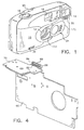
- Figure 2 illustrates a back view of the camera shown in Figure 1 with a film door 34 located in an open position.
- the film door 34 is coupled to a main camera frame 36 by a hinge assembly 38 and latched in a closed position by a latching mechanism 40 in a conventional manner.
- the film door 34 preferably includes a film window 42 that provides a camera operator with a view of the film chamber 46 of the camera in which a film spindle 44 is located. Film is advanced from a film canister loaded on the film spindle 44 in the film chamber 46 to a film take-up spool 48 by a motorized drive unit (not shown), and is maintained in proper position along a film transport path between the film chamber 46 and film take-up spool 48 by a film sprocket assembly 50.
- the film sprocket assembly 50 also serves to reset the camera's shutter mechanism and can act as a detent for a mechanical exposure counter 20.
- a film rewind control switch 52 is provided to cause the motorized drive unit to drive the film spindle 44 in a rewind direction when activated by the camera operator.
- Other illustrated features include a flash-ready indicator lamp 54 located adjacent to an optical viewfinder eyepiece 56 and a hinged battery compartment door 58.
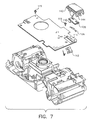
- Figure 3 illustrates a front view of the camera with the front housing cover 10 removed.
- a main printed circuit board 60 is attached to a front portion of the main camera frame 36.
- Various electronic control circuits for the camera including a main camera control processor and flash control circuitry, are located on the main printed circuit board 60.
- discrete circuit elements such as the electronic flash sensor 28 and an electronic flash operation control switch 62, are also located on the main printed circuit board 60.
- a mechanical plate 64 is attached to a top portion of the main camera frame 36 that includes a viewfinder retainer structure 66 and a motorized drive unit housing 68, respectively utilized to retain optical elements of the optical viewfinder 16 and a gear train of the motorized drive unit (not shown).
- An auxiliary printed circuit board 70 is also attached to the top portion of the main camera frame 36, such that a plane defined by the auxiliary printed circuit board 70 is substantially perpendicular to a plane defined by the main printed circuit board 60.
- the auxiliary printed circuit board 70 is preferably utilized to retain the red-eye reduction lamp 26 and the flash ready indicator lamp 54, as well as providing electrical coupling to battery leads 76.
- a rear housing cover 72 is also attached to a rear portion of the main camera frame 36.
- the auxiliary printed circuit board 70 includes slots 74 that are utilized to retain the battery leads 76.
- the battery leads 76 extend into a battery compartment of the camera located below the auxiliary printed circuit board 70 and behind the electronic flash unit 14.
- the slots 74 and battery leads 76 are preferably sized to provide a mechanical "snap" fit, such that the battery leads 76 are physically held in place by the slots 74.
- the use of a mechanical snap fit for the slots 74 and battery leads 76 greatly simplifies the manufacturing process, by allowing the battery leads 76 to be properly located and held in place until a soldering operation can be performed to connect the battery leads 76 to electrical leads 78 that are provided, either adjacent to or immediately surrounding the slots 74, on the auxiliary printed circuit board 70. Any excess in the length of the battery leads 76 is preferably trimmed once the soldering operation is completed.
- a mechanical snap fit is preferred to physically hold the battery leads 76 in place while awaiting a soldering operation, the battery leads 76 need only be retained within the slots 74 in a manner to permit the proper soldering of the battery leads 76 to the electrical leads 78.
- the main printed circuit board 60 and the auxiliary secondary printed circuit board 70 are electrically coupled together to permit the transfer of electrical control and power signals between the two circuit boards.
- Conventional techniques such as flexible circuits, ribbon cables or discrete wires can be utilized to provide the required electrical coupling.
- electrical leads of the main printed circuit board 60 and the auxiliary printed circuit board 70 be directed coupled.
- Figure 4 illustrates an embodiment of the invention in which the main printed circuit board 60 and the auxiliary printed circuit board 70 are located substantially perpendicular, such that electrical leads 80 on the main printed circuit board 60 perpendicularly abut electrical leads 82 on the auxiliary printed circuit board 70.
- a soldering operation is then performed to connect the electrical leads 80 to the electrical leads 82 with a solder connection joint 84 located at the junction of the perpendicular abutment.
- the use of the perpendicularly abutting electrical leads 80, 82 reduces the time required to solder the connections between the main printed circuit board 60 and the auxiliary printed circuit board 70 as compared with the time generally required to solder flexible circuits or discrete wires.
- the electrical leads 82 of the auxiliary printed circuit board 70 could also be located on a lower surface thereof, as viewed in the Figure 4, such that the solder connection joint 84 would be located at a connection point 86 underneath the auxiliary printed circuit board 70.
- the portion of the main printed circuit board 60 containing the electrical leads 80 would not have to extend past the auxiliary printed circuit board 70 as shown in Figure 4, but instead, would terminate at the upper surface of the auxiliary printed circuit board 70.
- Other variations, of course, are possible depending on the layout of the main and auxiliary printed circuit boards 60, 70 within the main body of the camera.
- Figure 5 illustrates a partial exploded view of the camera structure illustrated in Figure 3.
- the film rewind control switch 52 is located between the auxiliary printed circuit board 70 and the main camera frame 36, and includes a main switch body 87 having a flexible slide element 88 that fits into a slot 90 in the main camera frame 36.
- Electrical contact wiper elements 92 are provided on a top surface of the main switch body 87. The electrical contact wiper elements 92 come into contact with electrical contacts 94 (shown by dotted lines) located on the bottom side of the auxiliary printed circuit board 70, as the film rewind control switch 52 is moved back and forth between an initial position and a film rewind position.
- An extension member 96 is also provided as part of the main switch body 87.
- the extension member 96 contacts and activates a switch element 98 provided on the top surface of the secondary printed circuit board 70.
- the switch element 98 constitutes a portion of a current drain protection circuit.
- the film rewind control switch 52 interacts with circuit elements on both sides of the auxiliary printed circuit board 70 to provide a compact and efficient design. The positioning of the auxiliary printed circuit board 70 with respect to the film rewind control switch 52 permits the flash-ready indicator lamp 54 to be readily aligned with an indicator lamp hole 99 located on the rear cover housing 72 of the camera.
- the flexible slide element 88 includes a ramped end 100 that rides over and snaps in place behind a stop mechanism 102 provided on the film door 34, when the film door 34 is closed and the film rewind control switch 52 is moved to the film rewind position in the direction indicated by the arrow "A".
- the stop mechanism 102 is pulled out of the path of the flexible slide element 88 along the path indicated by arrow "B”, and the film rewind control switch 52 is pulled back to its initial position by a biasing spring 104 shown in Figure 5.
- the relative positioning of the ramped end 100 of the flexible slide element 88 and the stop mechanism 102 when the film door is opened is shown in Figure 1.
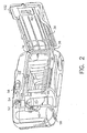
- Figure 7 illustrates a partial exploded view of the camera structure illustrated in Figure 3 detailing the assembly of the electronic flash unit 14 and the fill-flash/flash-defeat control switch assembly 30 with respect to the main camera frame 36 and the main printed circuit board 60.
- the main printed circuit board 60 includes an electrical contact group 114 located on a front surface thereof that is utilized to provide signals corresponding to the operation of the fill-flash/flash-defeat control functions of the camera.
- An electrical contact wiper element 106 is coupled to a wiper carrier assembly 108, which includes a post element 110 that is captured in a slot provided in the fill-flash/flash-off switch element 112.
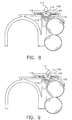
- the fill-flash/flash-off switch element 112 is pivotally mounted to the main camera frame 36 and is biased to a neutral position by a spring element 116 as shown. Movement of the fill-flash/flash-defeat switch element 112 imparts a force to the post 110 of the wiper carrier assembly 108 causing the wiper carrier assembly 108, including the electrical contact wiper element 106 coupled thereto, to move laterally back and forth to selectively bring the electrical contact wiper element 106 into contact with either the left electrical contact 118 (to supply a fill flash condition signal to a control circuit of the camera) or the right electrical contact 120 of the electrical contact group 114 as illustrated in Figure 9 (to supply a flash defeat condition signal to the control circuit of the camera).
- the electronic flash unit 14 includes a transparent cover 122 that snaps onto a reflector mounting structure 124.
- a reflector plate 126 and a flash tube 128 are retained within the reflector mounting structure 124.
- the reflector mounting structure 124 includes a flexible extension arm 130 that snaps into a relief opening 132 provided in the main camera frame 36.
- the entire flash unit 14 is resiliently biased outward into position against the front camera housing 10 by an elastic band 134 that is looped around the ends of the flash tube 128 (indicated by dashed line) and passes between the reflector mounting structure 124 and the main camera frame 36 in a channel 136.
- guide openings 138 are provided to permit the wiper carrier assembly 108 to slide back and forth over guide ribs 140 that extend from the main camera frame 36.
- the sequence of assembly includes mounting the fill-flash/flash-defeat switch element 112 to the main camera frame 36, mounting the main circuit board 60 onto the main camera frame 36 with mounting screws 115 to locate and retain the fill-flash/flash-defeat switch element 112 in place, positioning the wiper carrier assembly 108 so that the post 110 is captured by the fill-flash/flash-defeat switch element 112 and locating the guide ribs 140 within the guide openings 138, and snapping the reflector mounting structure 124 into the main camera frame 36.
- the overall structure is simple to assemble without requiring mechanical fasteners other than the screws 115 used to attach the main circuit board 60 to the main camera frame 36.
- the transparent cover 122 is also provided with a mechanism to permit easy attachment of the reflector mounting structure 124.
- a first side of a top edge of the transparent cover 122 is provided with an "L" shaped leg 142 and a second side of the top edge of the transparent cover 122 is provided with a substantially straight leg 144 that is longer than the L-shaped leg 142.
- An identical L-shaped leg 142 and an identical straight leg 144 are also provided at a bottom edge of the transparent cover 122 as shown in Figure 7.
- the reflector mounting structure 124 is provided with a straight extension portion 146 and an angled extension portion 148 that respectively correspond to the L-shaped leg 142 and the straight leg 144 of the transparent cover 122.
- the transparent cover 122 is engaged with a first side of the reflector mounting structure 124 such that the L-shaped leg 142 extends over the straight extension portion 146 as shown in Figure 12.
- a hook protrusion 149 extending downward from the tip of the L-shaped leg 142 (or upward in the case of the lower leg illustrated in Figure 7) is placed behind a back surface 150 of the straight extension portion 146. Accordingly, the L-shaped leg 142 pivots on the straight extension portion 146 in a hinged manner, thereby allowing the straight leg 144 to be rotated toward the angled extension portion 148 of the reflector mounting structure 124.
- a hook protrusion 152 extending downward from the straight leg 144 latches over a back edge 154 of the angled extension portion 148 to secure the transparent cover 122 to the reflector mounting structure 124 with a snap fit that prevents contaminants from entering the electronic flash unit 14.
- the flash operation control switch 62 includes a leaf spring switch element 156 that is attached the main circuit board 60 at a first end 158 and has a second end 160 that is shaped to form first and second opposing contact points 162, 164 as shown in Figure 14.
- the second end 160 of the leaf spring switch element 156 including the first and second opposing contact points 162, 164, is located between an electrical contact pad 166 provided on the main printed circuit board 60 and a "bridge" contact 168 that is coupled to the main printed circuit board 60 at both ends, so that the bridge contact 168 extends up and over the second end 160 of the leaf spring switch element 156 as shown in Figure 13.
- the leaf spring switch element 156 is biased upward so that a second opposing contact point 164 comes into electrical contact with the bridge contact 168 when the sliding lens cover 24 is in the closed position.
- the leaf spring switch element 156 is configured to act as a double-throw-single-pole switch to disable a flash charger circuit for the electronic flash unit 14 and to turn off the flash ready indicator lamp 54.
- the flash charger circuit and the flash ready indicator lamp 54 are turned on when the leaf spring switch element 156 is pushed downward so that the first opposing contact point 162 makes contact with the contact pad 166.
- the leaf spring switch element 156 is controlled by the sliding lens cover assembly 24.
- the sliding lens cover assembly 24 includes an interior slide plate 170 that is coupled to an exterior slide plate 172 by a screw that slides within a slot 173 provided in the front housing cover 10 (See Figure 1).
- the interior slide plate 170 includes guide protrusions 174 that ride on ridges provided on the inside of the front housing cover 10.
- the slide plate 170 comes into contact with an upwardly extending contact point 176 of the leaf spring switch element 156, and pushes downward on the contact point 176 shown in Figure 14 to move the first opposing contact point 162 into contact with the electrical contact pad 166 provided on the main printed circuit board 60 with a force of approximately five ounces.
- the simple design of the leaf spring switch element 156 can easily handle currents in excess of two amps.
- the illustrated embodiment for example, utilizes a leaf spring switch element 156 manufactured from beryllium copper having a width of 3.5 mm, a thickness of 0.13 mm and a length of approximately 15 mm that switches between five and six amps of current. Greater current capacities are also possible depending on type and dimensions of the material utilized.
- the second end 160 of the leaf spring switch element 156 is also slit to provide multiple contact points, with each contact point being capable of handling the full current capacity of the leaf spring switch element 156, thereby if one contact point becomes damaged or dirty.
- leaf spring switch element 156 is the ability to clean contact surfaces during operation by providing a sliding contact motion.
- Figure 22 illustrates multiple positions of the leaf spring switch element 156 during operation.
- position A the sliding lens cover assembly 24 is in the closed position such that the first opposing contact point 164 of the leaf spring switch element 156 is in contact with the bridge contact 168.
- the sliding lens cover assembly 24 is moved to the opened position, contact is made with the contacting point 176 and a downward force is applied to the leaf spring switch element 156 until the first opposing contact 162 comes into contact with the electrical contact pad 166 at an intermediate position B.
- the sliding lens cover assembly 24 continues to apply a force that causes the first opposing contact 162 to slide of the surface of the electrical contact pad 166, thereby causing a frictional contact that cleans the surfaces of the first opposing contact 162 and the electrical contact pad 166, until a final contact position C is reached.
- the shutter button assembly 18 includes a vertical sliding member 178 including a shutter button arm 180, a shutter actuation arm 182 and an electrical contact arm 184.
- the shutter actuation arm 182 includes a shutter actuation member 186 that contacts a shutter release 302 (either a mechanical member, such as a high energy lever, or an electrical switch) located on the main camera frame 36, when the sliding member 178 is pushed downward by the application of a force to the shutter button arm 180 by a camera operator.
- electrical contact wiper elements 188 provided on the electrical contact arm 184 are moved downward into contact with electrical contact pads 190 provided on the main printed circuit board 60 as shown in Figure 15.
- the electrical contact pads 190 are arranged to cause a sequence of signals to be provided to the electrical control circuits of the camera so that various pre-exposure operations can be performed prior to activation of the shutter release 302 by the shutter actuation member 182. Relative positions of wiper elements 188 and pads 190 can also be varied in other ways to complete electrical circuits during operation of the shutter button assembly, as desired.
- the sliding member 178 is movably mounted to the main camera frame 36 and slides back and forth over protrusions 192 that fit into slots 194 provided in the sliding member 178.
- the protrusions 192 are internally threaded to permit the insertion of a retainer screw (not shown) to prevent the sliding member 178 from slipping off.
- a biasing member or spring 196 is provided to bias the sliding member 178 in an upward direction.
- the interior slide plate 170 of the sliding lens cover assembly 24 includes a retainer 198 that slides over the electrical contact arm 184 of the sliding member 178.
- the retainer 198 controls the amount of contact pressure applied to the electrical contact wiper elements 188 provided on the electrical contact arm 184.
- the interior slide plate 170 also includes a shutter lock member 200 that interacts with the shutter actuation arm 182. Specifically, when the sliding lens cover assembly 24 is in the closed position, the shutter lock member 200 is located under the shutter actuation arm 182, thereby preventing the downward movement of the vertical sliding member 178 as shown in Figure 13. Accordingly, the sliding lens cover assembly 24 interacts with the other camera components in the illustrated embodiment to provide a shutter lock, activation of the flash control circuitry, and to control the contact pressure applied to the electrical contact wiper elements 188.
- FIG. 17 and 18 illustrates a further embodiment of the invention in which the electrical contact arm 184 is attached to the vertical sliding member 178 of the shutter button assembly 18 via a pivot yoke 202.
- the pivot yoke 202 allows the electrical contact arm 184 to move in an arc, thereby allowing the electrical contact wiper elements 188 to sweep over arched or curved contact pads provided on the main printed circuit board 60.
- FIG. 19 A still further embodiment of the invention is illustrated in Figures 19 and 20 in which the flash control switch 62 take the form of a rotary switch including a fixed switch mount 204 that is coupled to the circuit board 60 and a rotating wiper assembly 206 that is spring loaded by a spring 208 and rotates to make contact with contact pads 210 provided on the circuit board 60 when contacted by the interior sliding member 170 as shown in Figure 20.
- the flash control switch 62 take the form of a rotary switch including a fixed switch mount 204 that is coupled to the circuit board 60 and a rotating wiper assembly 206 that is spring loaded by a spring 208 and rotates to make contact with contact pads 210 provided on the circuit board 60 when contacted by the interior sliding member 170 as shown in Figure 20.
- the camera has a timer 300 that interacts with the shutter release 302 to allow film exposure after a predetermined delay.
- the timer 300 and related camera features are described below in terms of one particular embodiment. It will be understood, however, that features can be varied in a manner consistent with the claims.
- the timer 300 includes a delay counter 304 and a linkage 306 coupled to the delay counter 304 for movement, in synchronism with the delay counter 304, from a start configuration to an exposure configuration and from the exposure configuration to an end configuration.
- the timer 300 shown in Figures 21-30 is mechanical and has a frame 308 that is fixedly mounted in the camera body by some means, such as fasteners, heat fusion, or adhesive.
- the frame 308 can be made in two or more pieces held together by fasteners 301 or the like.
- the frame 308 supports the delay counter 304: a spring 310, a winder 312, a gear train 314, and an escapement 316; and the linkage 306.
- the gear train 314 is mounted in the frame 308.
- the spring 310 is mounted in the frame 308 and bears on a projection 320 of an input gear unit 318 of the gear train 314, mechanically loading the input gear unit 318 and urging its rotation.
- gear unit is used herein to refer to an assembly of two or more gears fixed for rotation about a common axis. Connecting gear units 322, 324,326 are arranged in mechanical sequence between the input gear unit 318 and an output gear unit 328. The output gear unit 328 drives an escapement 316. Details of gear trains 314 and escapements 316 suitable for this purpose, are well known to those of skill in the art.
- the winder 312 is mechanically connected to the spring 310 and is movable from an unwound position to a wound position to load the spring 310.
- the timer 300 works with the sliding member 178 and the shutter release 302.
- the sliding member 178 includes the shutter button arm 180, the shutter actuation arm 182, and the timer release arm 330.
- the sliding member 178 is moveable from a first position, shown in Figure 22, to a second position, shown in Figure 21, by application of a force to the shutter button arm 180.
- a biasing member biases the sliding member 178 for return from the second position to the first position.
- the directions of movement of the sliding member 178, between the first and second positions, are indicated by a double headed arrow 332.
- the sliding member 178 can include an electrical contact arm 184, as shown in Figures 25-29.
- the electrical contact arm 184 has a plurality of electrical contact elements 188 that sweep past contact pads 190 when the sliding member 178 is moved.
- the electrical contact elements 188 are disposed so as to individually engage respective contact pads 190 when the sliding member 178 is in one of the first position, the second position, and a plurality of positions intermediate between the first and second positions.
- the shutter release 302 is mounted in the camera body and is movable from an initial position to a stopped position and from the stopped position to the released position.
- the shutter release 302 is detained in the initial position by the shutter actuation arm 182 (not shown in Figure 22) when the sliding member 178 is in the first position.
- the shutter release 302 is released from the shutter actuation arm 182 when the sliding member 178 is in the second position.
- the shutter release 302 is biased toward the released position.
- the shutter release 302 can be a high energy lever, that is, a pivotable mechanical element that is spring-biased by a spring element 324, toward the released position. The high energy lever is thus fully charged in the initial position.
- the linkage 306 moves, in synchronism with the delay counter 304.
- the linkage 306 is mechanically coupled to the gear train 314 for movement with the gear train 314 from a start configuration to an exposure configuration and from the exposure configuration to an end configuration.
- a convenient mechanical coupling between the gear train 314 and the linkage 306 is shown in the figures.
- a boss 334 protrudes from the input gear unit 318 and engages a matching hole (not shown) in the guide plate 336 of the linkage 306.
- the boss 334 can include a roller bearing or the like to reduce friction.
- the winder 312 is a protrusion that is fixed to the guide plate 336 and the unwound and wound positions of the winder 312 correspond to linkage 306 start and end configurations, respectively.
- the start and end configurations of the linkage 306 are defined by margins 338 of the timer frame 308, that engage the boss 334 in the start and end configurations (the location of the boss 334 in the start configuration is indicated by a circled "X" bearing reference numeral 335) and deter further movement of the linkage 306 in opposed winding and unwinding directions.
- the linkage 306 has a stop 338 that is disposed to arrest the shutter release 302 when the linkage 306 is in the start configuration and the shutter release 302 is in the stopped position, and to be free of the shutter release 302 when the linkage 306 is in the end or exposure configuration.
- the stop 338 has a contact surface 340 at one end and a follower 342 at the other end.
- the contact surface 340 abuts the shutter release 302 when the shutter release 302 is in the stopped position and prevents the shutter release 302 from continuing resiliently urged movement to the end position.
- the follower 342 is trapped within a track 344 in the guide plate 336 and moves along the track 344 in unison with the movement of the guide plate 336 and gear train 314.
- Motion of the guide plate 336 is limited by appropriate guides.
- slot 333 in the guide plate 336 and matching guide pin 335 on the frame limit the guide plate 336 to substantially linear movement in the directions indicated by double-headed arrow 346.
- the stop 338 moves in parallel with the direction of motion of the sliding member, indicated by double-headed arrow 332.
- the track 344 extends, at least in part, oblique to that direction.
- the guide plate 336 can have one or more portions parallel to the direction indicated by arrow 346, if it is desired to provide for additional travel of guide plate 336 unaccompanied by simultaneous movement of the stop 338.
- the timer includes a holdfast 348 that grips the sliding member 178 when the sliding member 178 is in the second position and the linkage 306 is in one of the start and exposure configurations, and is released from the sliding member 178 when the linkage 306 is in the end configuration.
- Figure 21 shows the position of the holdfast 348 when the sliding member 178 is in the second position.
- the holdfast 348 is fixed to the timer frame 308 (this is shown mostly clearly in Figure 30) and is resiliently pivotable relative to the timer frame 308.
- the holdfast can, for example, be a thin piece of flexible metal.
- the sliding member 178 has a tab 350 that is configured so as to engage a grip portion 352 of the holdfast 348 when the grip portion 352 and tab 350 are brought together.
- the tab 350 is released from the holdfast 348 when, as the guide plate 336 moves toward the end configuration, a projection 354 of the guide plate 336 encounters the holdfast 348 and resiliently bends the holdfast 348 away from the tab 350.
- timer operation provides a dwell time period between picture exposure, that is, movement of the shutter release 302 to the end position; and spring-biased return of the sliding member 178 to the first position.
- the number of parts moving during picture exposure is reduced, decreasing the risk of deleterious vibration during picture exposure.
- the dwell time period can also be utilized in controlling electrical functions of the camera. Wiper elements 188 and contact pads 190 can be configured to use the dwell time period for prolonged actuation of electrical features.
- the red eye reduction lamp 26 can be actuated during the dwell time period as an indicator to the camera user that timed exposure operation is not yet completed.
- a flash unit can be charged or maintained in an operational condition during the dwell time period.
- Optical fat bit writers and date-backs can be actuated in the same manner during the dwell time period.
- the timer 300 is actuated and deactuated by the timer release arm 330.
- the timer release arm 330 is preferably an arm of the sliding member 178 and moves between the same first and second positions as the sliding member 178.
- the timer release arm 330 actuates and deactuates the timer by halting the gear train 314 or allowing the gear train 314 to move. (With a mechanical timer the timer is necessarily wound as a preliminary to actuation.)
- an intermediate gear unit 356 (one of the downstream gear units 322,324,326 of the gear train 314) has a lower mechanical advantage in the sequence of gear units than the input and output gear units 318,328.
- the intermediate gear unit has a minor gear 358 and a major gear 360 having a great number of teeth.
- An example of a suitable intermediate gear unit 356 has a major to minor gear tooth ratio of 100:1 or greater.
- a preferred ratio is 200:1 or greater, and a still more preferred ratio is 400:1.
- the low mechanical advantage of the intermediate gear unit 356 allows the timer release arm 330 to stall the gear train 314 using a small force by contacting the intermediate gear unit 356.
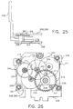
- the timer release arm 330 contact the intermediate gear unit 356 on a contact surface 362 (shown in Figure 25) that is spaced apart from the teeth of the gear unit.
- the contact between the timer release arm 330 and contact surface 362 can be limited to a minimal force required to provide necessary friction. It is preferred, however, that the be sufficient to clamp the intermediate gear unit 356 between the timer release arm 330 and the timer frame 308. This is illustrated in Figure 23.
- the timer release arm 330 and intermediate gear unit are shown in solid lines in the locations assumed when the sliding member 178 is in a second position. The timer release arm 330 is displaced from the intermediate gear unit 356.
- the dashed line shows the location of the timer release arm 330 when the linkage 306 is in the start configuration and the timer release arm 330 is in the first position. It is not illustrated, but the intermediate gear unit 356, in this case, is displaced or deformed, or both; such that the major gear 360 is clamped between the timer release arm 330 and the adjoining portion of the timer frame 308.
- the actual distortion of the intermediate gear unit 356 is small, and can be readily accommodated by appropriate tolerances in the timer frame 308 or use of slightly flexible material for the intermediate gear unit 356, or both. When clamped, the gear train 314 is unlikely to move even when the camera is jarred.
- a push-pull 372 is movable between a primary position and a secondary position in directions indicated by double-headed arrow 346. These directions are substantially perpendicular to the directions of movement of the sliding member 178, as shown by double-headed arrow 332.
- the push-pull 372 in the embodiment shown in the figures is a sliding lens cover assembly 24; however, the push-pull can be any of a variety of appropriately positioned and sized camera elements movable, by the user, in a similar manner.
- the push-pull can be a toggle or a slidable front cover member.
- the push-pull be movable to cover the taking lens, because this provides a very clear indication to the camera user as to when the push-pull is in a non-picture-taking position.
- the push-pull 372 described is a lens cover assembly.
- the push-pull 372 has an exterior portion that is movable back and forth by the camera user.
- the push-pull 372 has a circular opening 362 that unblocks the taking lens 12 when the push-pull 372 is in a primary position and blocks the taking lens 12 when the push-pull 372 is in a secondary position.
- the push-pull 372 has a shutter lock member 200 that prevents movement of the sliding member 178 from the first position to the second position when the push-pull 372 is in the secondary position, by interfering with the shutter actuation arm 182.
- the push-pull 372 is separated from the sliding member 178 in a direction parallel to arrow 332 by a dimension "Z" when the sliding member 178 is in the first position and the push-pull 372 is in the secondary position.
- the first and second positions of the sliding member 178 are spaced apart, in a direction parallel to arrow 332, by a dimension "Y".
- the sliding member 178 When the push-pull is in the secondary position, the sliding member 178 is movable out of the first position, over the distance "Z" to an offset position. This movement of the sliding member 178 from the first position to the offset position is insufficient to allow the shutter release 302 to move out of the initial position or to latch the tab 350 to the holdfast 348. This movement of the sliding member 178 from the first position to the offset position is sufficient to actuate the timer, allowing the timer to unwind without requiring a picture exposure. This allows the camera user to deactuate the timer 300 without exposing a frame of film.
Landscapes
- Physics & Mathematics (AREA)
- General Physics & Mathematics (AREA)
- Details Of Cameras Including Film Mechanisms (AREA)
- Camera Bodies And Camera Details Or Accessories (AREA)
- Shutter-Related Mechanisms (AREA)
- Stroboscope Apparatuses (AREA)
Description
- The invention relates to photography and photographic equipment and more particularly relates to an improved camera and mechanical self timer.
- Photographic cameras have long used self timers to allow delayed picture exposure. Simple and inexpensive mechanical self timers have remained problematic, because of the number and complexity of parts needed to actuate and deactuate the prewound timer. Selftimer devices which comprise a gear and a timer release arm are described in documents US-A-4 205 908 and US-A-5 105 213.
- It would thus be desirable to provide an improved camera and timer in which the number and complexity of parts used to actuate and deactuate the prewound timer is minimized.
- The invention is defined by the claims. The invention, in its broader aspects, provides a camera and mechanical self timer. The camera includes a camera body, a shutter release, the timer, and a timer release arm. The shutter release is disposed in the camera body and is movable from a stopped position to a released position. The shutter release is biased toward the released position. The mechanical timer includes: a spring, a winder, a gear train, an escapement, and a linkage. The winder is mechanically connected to the spring and is movable into a wound position to load the spring. The gear train includes input, output, and intermediate gear units. The input gear unit is driven by the spring. The intermediate gear unit is disposed in mechanical sequence between the input and output gear units. The intermediate gear unit has a lower mechanical advantage in the sequence, relative to the input and output gear units. The escapement is driven by the output gear unit. The linkage is coupled to the gear train for movement with the gear train between start an end configurations. The linkage has a stop disposed to arrest the shutter release when the linkage is in the start configuration and the shutter release is in the stopped position. The stop is free of the shutter release when the linkage is in the end configuration. The timer release arm is disposed in the camera body and is movable between first and second positions. The timer release arm stalls the intermediate gear unit when the linkage is in the start configuration and the timer release arm is in the first position. The timer release arm is displaced from the intermediate gear unit when the timer release arm is in the second position.
- It is an advantageous effect of at least some of the embodiments of the invention that an improved camera and timer are provided in which the number and complexity of parts used to actuate and deactuate the prewound timer is minimized.
- The above-mentioned and other features and objects of this invention and the manner of attaining them will become more apparent and the invention itself will be better understood by reference to the following description of an embodiment of the invention taken in conjunction with the accompanying figures wherein:
- Figure 1 is a front perspective view of a photographic camera in accordance with the invention;
- Figure 2 is a rear perspective view of the photographic camera illustrated in Figure 1;
- Figure 3 is a front view of the camera illustrated in Figure 1 with the front housing cover removed.
- Figure 4 illustrates the electrical coupling of a main printed circuit board and an auxiliary printed circuit board incorporated in the camera of Figure 1 utilizing abutting electrical contacts;
- Figure 5 is a partial exploded view of the camera illustrated in Figure 1;
- Figure 6 is a perspective view of a film rewind control switch utilized in the camera illustrated in Figure 1;
- Figure 7 is a partial exploded view of the attachment of an electronic flash unit to a main camera frame illustrated in Figure 3;
- Figs. 8 and 9 are bottom views illustrating the operation of a fill-flash/flash-defeat switch element utilized in the camera illustrated in Figure 1;
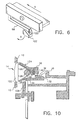
- Figure 10 is a side view illustrating the attachment of a wiper carrier assembly and an electronic flash unit;
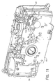
- Figure 11 is a perspective front view of the camera illustrated in Figure 3 with the wiper carrier assembly shown in place;
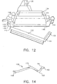
- Figure 12 is a top view illustrating the attachment of a transparent cover to a reflector body structure of the flash unit illustrated in Figure 10;
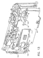
- Figure 13 is a front perspective view of the camera illustrated in Figure 3 with an internal slide member of a sliding lens cover assembly located in a closed position;
- Figure 14 illustrates the structure of a leaf spring switch element;
- Figure 15 is a front perspective view of the camera illustrated in Figure 3 with an internal slide member of a sliding lens cover assembly located in an open position;
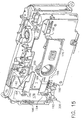
- Figure 16 illustrates a shutter button assembly;
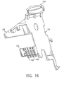
- Figure 17 is a front perspective view of a second embodiment of the invention that utilizes a pivot yoke to permit pivotal movement of an electrical contact arm of a shutter button assembly;
- Figure 18 is a rear perspective view of the embodiment shown in Figure 17;
- Figure 19 is an exploded view of a third embodiment of the invention that incorporates a rotary switch;
- Figure 20 is a perspective view of the embodiment illustrated in Figure 19 with an internal slide member of a sliding lens cover making contact with the rotary switch.
- Figure 21 is a circuit diagram illustrating the interconnection of a flash charger circuit and flash-ready indicator lamp with a flash operation control switch; and
- Figure 22 is a side view of the flash operation control switch in different operating positions.
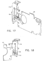
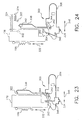
- Figure 23 is a semi-diagrammatical view of an embodiment of the invention illustrating the timer. Shown are the sliding member, biasing member, timer linkage, holdfast, gear train boss, and the contact surface of the shutter release; shown, in solid lines with the sliding member in the second position, the shutter release in a stopped position, and the linkage in the start configuration. The location of the follower of the linkage arm, when the linkage is in an exposure configuration is indicated by dashed lines. For clarity, the timer release are is not shown.
- Figure 24 is the same view as in Figure 23, but shows the sliding member in the first position, the linkage in the end configuration, and the shutter release in the released position in solid lines. The location of the contact surface of the shutter release when the shutter release in the initial position is indicated by a dashed line. For clarity, the shutter actuation arm of the sliding member is not shown.
- Figure 25 is a semi-diagrammatical side view of the timer release arm and the timer of the camera of Figure 23. The timer release arm is shown by a solid line in the second position, by a dashed line in the first position, and by a dotted line in the offset position. The intermediate gear is shown by a solid line, in the location the intermediate gear occupies when the timer release arm is in the second position or offset position.
- Figure 26 is a semi-diagrammatical horizontal cross-section through the timer of Figure 23. The linkage is not shown, except for the link post. The timer is shown in the end configuration. The location of the link post in the start configuration is indicated by an "X" within a circle.
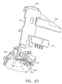
- Figure 27 is a bottom perspective view of the sliding member and timer of Figure 23. The linkage is not shown.
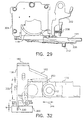
- Figure 28 is a rear perspective view of the sliding member and timer of Figure 27.
- Figure 29 is a top view of the sliding member and timer of Figure 27.
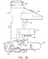
- Figure 30 is a front perspective view of the sliding member and timer of Figure 27. The sliding member in the second position and the linkage is in the start configuration.
- Figure 31 is the same view as Figure 30, but the sliding member is in the first position and the linkage is in the end configuration.
- Figure 32 is a semi-diagrammatical view of the sliding member, timer, and lens cover push-pull of the camera of Figure 27. The sliding member is shown in the first and second positions by solid and dashed lines, respectively. The push-pull is shown in the primary position in solid lines and in the secondary position in dashed lines.
-
- The invention is directed to an improved camera that includes a
self timer 300 and to thetimer 300 itself. In the following, Figures 1-20 are generally discussed in relation to general features of the camera; and Figures 21-30 are discussed in relation to detailed features of the timer and related structures. It will be understood that some features shown in Figures 21-30 are not illustrated in the other figures, but would be incorporated in a camera of the invention in a manner consistent with the disclosure of those features presented herein. - Figure 1 illustrates a photographic camera in accordance with the invention that includes a
front housing cover 10, alens 12, anelectronic flash unit 14, anoptical viewfinder 16, ashutter button assembly 18 and anexposure counter 20. A slidinglens cover assembly 24 is mounted to thefront housing cover 10, such that movement of the slidinglens cover assembly 24 from a closed or secondary position to an open or primary position activates electronic control circuitry of the photographic camera as will be described in greater detail. A red-eye reduction lamp 26, anelectronic flash sensor 28 and a fill-flash/flash-defeatcontrol switch assembly 30 are preferably located adjacent to theelectronic flash unit 14 as illustrated. A self-timer control button 32 is provided on the front of the camera to control the operation of a mechanical orelectrical timer 300 mounted within the main body of the camera. - Figure 2 illustrates a back view of the camera shown in Figure 1 with a
film door 34 located in an open position. Thefilm door 34 is coupled to amain camera frame 36 by ahinge assembly 38 and latched in a closed position by alatching mechanism 40 in a conventional manner. Thefilm door 34 preferably includes afilm window 42 that provides a camera operator with a view of thefilm chamber 46 of the camera in which afilm spindle 44 is located. Film is advanced from a film canister loaded on thefilm spindle 44 in thefilm chamber 46 to a film take-upspool 48 by a motorized drive unit (not shown), and is maintained in proper position along a film transport path between thefilm chamber 46 and film take-upspool 48 by afilm sprocket assembly 50. Thefilm sprocket assembly 50 also serves to reset the camera's shutter mechanism and can act as a detent for amechanical exposure counter 20. A filmrewind control switch 52 is provided to cause the motorized drive unit to drive thefilm spindle 44 in a rewind direction when activated by the camera operator. Other illustrated features include a flash-ready indicator lamp 54 located adjacent to anoptical viewfinder eyepiece 56 and a hingedbattery compartment door 58. - Figure 3 illustrates a front view of the camera with the
front housing cover 10 removed. A main printedcircuit board 60 is attached to a front portion of themain camera frame 36. Various electronic control circuits for the camera, including a main camera control processor and flash control circuitry, are located on the main printedcircuit board 60. In addition, discrete circuit elements, such as theelectronic flash sensor 28 and an electronic flashoperation control switch 62, are also located on the main printedcircuit board 60. Amechanical plate 64 is attached to a top portion of themain camera frame 36 that includes aviewfinder retainer structure 66 and a motorizeddrive unit housing 68, respectively utilized to retain optical elements of theoptical viewfinder 16 and a gear train of the motorized drive unit (not shown). An auxiliary printedcircuit board 70 is also attached to the top portion of themain camera frame 36, such that a plane defined by the auxiliary printedcircuit board 70 is substantially perpendicular to a plane defined by the main printedcircuit board 60. The auxiliary printedcircuit board 70 is preferably utilized to retain the red-eye reduction lamp 26 and the flashready indicator lamp 54, as well as providing electrical coupling to battery leads 76. Arear housing cover 72 is also attached to a rear portion of themain camera frame 36. - In order to aid in the assembly of the overall camera structure, the auxiliary printed
circuit board 70 includesslots 74 that are utilized to retain the battery leads 76. The battery leads 76 extend into a battery compartment of the camera located below the auxiliary printedcircuit board 70 and behind theelectronic flash unit 14. Theslots 74 and battery leads 76 are preferably sized to provide a mechanical "snap" fit, such that the battery leads 76 are physically held in place by theslots 74. The use of a mechanical snap fit for theslots 74 and battery leads 76 greatly simplifies the manufacturing process, by allowing the battery leads 76 to be properly located and held in place until a soldering operation can be performed to connect the battery leads 76 toelectrical leads 78 that are provided, either adjacent to or immediately surrounding theslots 74, on the auxiliary printedcircuit board 70. Any excess in the length of the battery leads 76 is preferably trimmed once the soldering operation is completed. Although a mechanical snap fit is preferred to physically hold the battery leads 76 in place while awaiting a soldering operation, the battery leads 76 need only be retained within theslots 74 in a manner to permit the proper soldering of the battery leads 76 to the electrical leads 78. - The main printed
circuit board 60 and the auxiliary secondary printedcircuit board 70 are electrically coupled together to permit the transfer of electrical control and power signals between the two circuit boards. Conventional techniques such as flexible circuits, ribbon cables or discrete wires can be utilized to provide the required electrical coupling. In order to greatly simplify the manufacturing process, however, it would be preferred that electrical leads of the main printedcircuit board 60 and the auxiliary printedcircuit board 70 be directed coupled. Figure 4 illustrates an embodiment of the invention in which the main printedcircuit board 60 and the auxiliary printedcircuit board 70 are located substantially perpendicular, such that electrical leads 80 on the main printedcircuit board 60 perpendicularly abut electrical leads 82 on the auxiliary printedcircuit board 70. A soldering operation is then performed to connect the electrical leads 80 to the electrical leads 82 with a solder connection joint 84 located at the junction of the perpendicular abutment. The use of the perpendicularly abuttingelectrical leads circuit board 60 and the auxiliary printedcircuit board 70 as compared with the time generally required to solder flexible circuits or discrete wires. It should be noted that the electrical leads 82 of the auxiliary printedcircuit board 70 could also be located on a lower surface thereof, as viewed in the Figure 4, such that the solder connection joint 84 would be located at aconnection point 86 underneath the auxiliary printedcircuit board 70. In such an embodiment, the portion of the main printedcircuit board 60 containing the electrical leads 80 would not have to extend past the auxiliary printedcircuit board 70 as shown in Figure 4, but instead, would terminate at the upper surface of the auxiliary printedcircuit board 70. Other variations, of course, are possible depending on the layout of the main and auxiliary printedcircuit boards - Figure 5 illustrates a partial exploded view of the camera structure illustrated in Figure 3. As can be seen in Figure 5, the film
rewind control switch 52 is located between the auxiliary printedcircuit board 70 and themain camera frame 36, and includes amain switch body 87 having aflexible slide element 88 that fits into aslot 90 in themain camera frame 36. Electricalcontact wiper elements 92 are provided on a top surface of themain switch body 87. The electricalcontact wiper elements 92 come into contact with electrical contacts 94 (shown by dotted lines) located on the bottom side of the auxiliary printedcircuit board 70, as the filmrewind control switch 52 is moved back and forth between an initial position and a film rewind position. Anextension member 96 is also provided as part of themain switch body 87. Theextension member 96 contacts and activates aswitch element 98 provided on the top surface of the secondary printedcircuit board 70. In the illustrated embodiment, theswitch element 98 constitutes a portion of a current drain protection circuit. Accordingly, in the illustrated embodiment, the filmrewind control switch 52 interacts with circuit elements on both sides of the auxiliary printedcircuit board 70 to provide a compact and efficient design. The positioning of the auxiliary printedcircuit board 70 with respect to the film rewind control switch 52 permits the flash-ready indicator lamp 54 to be readily aligned with anindicator lamp hole 99 located on therear cover housing 72 of the camera. - An interface is provided between the film
rewind control switch 52 and thefilm door 34 to reset the filmrewind control switch 52 to the initial position when thefilm door 34 is opened to remove rewound film. Specifically, as shown in Figure 6, theflexible slide element 88 includes a rampedend 100 that rides over and snaps in place behind astop mechanism 102 provided on thefilm door 34, when thefilm door 34 is closed and the filmrewind control switch 52 is moved to the film rewind position in the direction indicated by the arrow "A". When thefilm door 34 is opened, thestop mechanism 102 is pulled out of the path of theflexible slide element 88 along the path indicated by arrow "B", and the filmrewind control switch 52 is pulled back to its initial position by a biasingspring 104 shown in Figure 5. The relative positioning of the rampedend 100 of theflexible slide element 88 and thestop mechanism 102 when the film door is opened is shown in Figure 1. - Figure 7 illustrates a partial exploded view of the camera structure illustrated in Figure 3 detailing the assembly of the
electronic flash unit 14 and the fill-flash/flash-defeatcontrol switch assembly 30 with respect to themain camera frame 36 and the main printedcircuit board 60. The main printedcircuit board 60 includes anelectrical contact group 114 located on a front surface thereof that is utilized to provide signals corresponding to the operation of the fill-flash/flash-defeat control functions of the camera. An electricalcontact wiper element 106 is coupled to awiper carrier assembly 108, which includes apost element 110 that is captured in a slot provided in the fill-flash/flash-off switch element 112. As shown in Figure 8, the fill-flash/flash-off switch element 112 is pivotally mounted to themain camera frame 36 and is biased to a neutral position by aspring element 116 as shown. Movement of the fill-flash/flash-defeat switch element 112 imparts a force to thepost 110 of thewiper carrier assembly 108 causing thewiper carrier assembly 108, including the electricalcontact wiper element 106 coupled thereto, to move laterally back and forth to selectively bring the electricalcontact wiper element 106 into contact with either the left electrical contact 118 (to supply a fill flash condition signal to a control circuit of the camera) or the rightelectrical contact 120 of theelectrical contact group 114 as illustrated in Figure 9 (to supply a flash defeat condition signal to the control circuit of the camera). - The top portion of the
wiper carrier assembly 108 is held in place against the main printedcircuit board 60 primarily by theelectronic flash unit 14. As shown in the Figure 10, theelectronic flash unit 14 includes atransparent cover 122 that snaps onto areflector mounting structure 124. Areflector plate 126 and aflash tube 128 are retained within thereflector mounting structure 124. Thereflector mounting structure 124 includes aflexible extension arm 130 that snaps into arelief opening 132 provided in themain camera frame 36. Theentire flash unit 14 is resiliently biased outward into position against thefront camera housing 10 by anelastic band 134 that is looped around the ends of the flash tube 128 (indicated by dashed line) and passes between thereflector mounting structure 124 and themain camera frame 36 in a channel 136. As shown in Figure 11, which provides a view with theelectronic flash unit 14 removed, guideopenings 138 are provided to permit thewiper carrier assembly 108 to slide back and forth overguide ribs 140 that extend from themain camera frame 36. The sequence of assembly includes mounting the fill-flash/flash-defeat switch element 112 to themain camera frame 36, mounting themain circuit board 60 onto themain camera frame 36 with mountingscrews 115 to locate and retain the fill-flash/flash-defeat switch element 112 in place, positioning thewiper carrier assembly 108 so that thepost 110 is captured by the fill-flash/flash-defeat switch element 112 and locating theguide ribs 140 within theguide openings 138, and snapping thereflector mounting structure 124 into themain camera frame 36. The overall structure is simple to assemble without requiring mechanical fasteners other than thescrews 115 used to attach themain circuit board 60 to themain camera frame 36. - The
transparent cover 122 is also provided with a mechanism to permit easy attachment of thereflector mounting structure 124. As shown in Figure 12, a first side of a top edge of thetransparent cover 122 is provided with an "L" shapedleg 142 and a second side of the top edge of thetransparent cover 122 is provided with a substantiallystraight leg 144 that is longer than the L-shapedleg 142. An identical L-shapedleg 142 and an identicalstraight leg 144 are also provided at a bottom edge of thetransparent cover 122 as shown in Figure 7. Thereflector mounting structure 124 is provided with a straight extension portion 146 and anangled extension portion 148 that respectively correspond to the L-shapedleg 142 and thestraight leg 144 of thetransparent cover 122. During assembly, thetransparent cover 122 is engaged with a first side of thereflector mounting structure 124 such that the L-shapedleg 142 extends over the straight extension portion 146 as shown in Figure 12. Ahook protrusion 149 extending downward from the tip of the L-shaped leg 142 (or upward in the case of the lower leg illustrated in Figure 7) is placed behind a back surface 150 of the straight extension portion 146. Accordingly, the L-shapedleg 142 pivots on the straight extension portion 146 in a hinged manner, thereby allowing thestraight leg 144 to be rotated toward theangled extension portion 148 of thereflector mounting structure 124. Ahook protrusion 152 extending downward from thestraight leg 144 latches over aback edge 154 of theangled extension portion 148 to secure thetransparent cover 122 to thereflector mounting structure 124 with a snap fit that prevents contaminants from entering theelectronic flash unit 14. - The specifics of the flash
operation control switch 62 will now be described with reference to Figures 13-15, 21 and 22. The flashoperation control switch 62 includes a leafspring switch element 156 that is attached themain circuit board 60 at afirst end 158 and has asecond end 160 that is shaped to form first and second opposing contact points 162, 164 as shown in Figure 14. Thesecond end 160 of the leafspring switch element 156, including the first and second opposing contact points 162, 164, is located between anelectrical contact pad 166 provided on the main printedcircuit board 60 and a "bridge"contact 168 that is coupled to the main printedcircuit board 60 at both ends, so that thebridge contact 168 extends up and over thesecond end 160 of the leafspring switch element 156 as shown in Figure 13. The leafspring switch element 156 is biased upward so that a second opposingcontact point 164 comes into electrical contact with thebridge contact 168 when the slidinglens cover 24 is in the closed position. In a preferred embodiment illustrated in Figure 21, the leafspring switch element 156 is configured to act as a double-throw-single-pole switch to disable a flash charger circuit for theelectronic flash unit 14 and to turn off the flashready indicator lamp 54. The flash charger circuit and the flashready indicator lamp 54 are turned on when the leafspring switch element 156 is pushed downward so that the first opposingcontact point 162 makes contact with thecontact pad 166. - The leaf
spring switch element 156 is controlled by the slidinglens cover assembly 24. Specifically, the slidinglens cover assembly 24 includes aninterior slide plate 170 that is coupled to anexterior slide plate 172 by a screw that slides within aslot 173 provided in the front housing cover 10 (See Figure 1). Theinterior slide plate 170 includes guideprotrusions 174 that ride on ridges provided on the inside of thefront housing cover 10. When the slidinglens cover assembly 24 is moved from the closed position shown in Figure 13 to an open position as shown in Figure 15, theslide plate 170 comes into contact with an upwardly extendingcontact point 176 of the leafspring switch element 156, and pushes downward on thecontact point 176 shown in Figure 14 to move the first opposingcontact point 162 into contact with theelectrical contact pad 166 provided on the main printedcircuit board 60 with a force of approximately five ounces. - The simple design of the leaf
spring switch element 156 can easily handle currents in excess of two amps. The illustrated embodiment, for example, utilizes a leafspring switch element 156 manufactured from beryllium copper having a width of 3.5 mm, a thickness of 0.13 mm and a length of approximately 15 mm that switches between five and six amps of current. Greater current capacities are also possible depending on type and dimensions of the material utilized. In desired, thesecond end 160 of the leafspring switch element 156 is also slit to provide multiple contact points, with each contact point being capable of handling the full current capacity of the leafspring switch element 156, thereby if one contact point becomes damaged or dirty. - Another advantage to the leaf
spring switch element 156 is the ability to clean contact surfaces during operation by providing a sliding contact motion. Figure 22 illustrates multiple positions of the leafspring switch element 156 during operation. In position A, the slidinglens cover assembly 24 is in the closed position such that the first opposingcontact point 164 of the leafspring switch element 156 is in contact with thebridge contact 168. As the slidinglens cover assembly 24 is moved to the opened position, contact is made with the contactingpoint 176 and a downward force is applied to the leafspring switch element 156 until the first opposingcontact 162 comes into contact with theelectrical contact pad 166 at an intermediate position B. The slidinglens cover assembly 24 continues to apply a force that causes the first opposingcontact 162 to slide of the surface of theelectrical contact pad 166, thereby causing a frictional contact that cleans the surfaces of the first opposingcontact 162 and theelectrical contact pad 166, until a final contact position C is reached. - The operation of the
shutter button assembly 18 will now be described with reference to Figures 13, 15 and 16. As shown in Figure 16, theshutter button assembly 18 includes a vertical slidingmember 178 including ashutter button arm 180, ashutter actuation arm 182 and anelectrical contact arm 184. (Atimer release arm 330 is discussed below.) Theshutter actuation arm 182 includes ashutter actuation member 186 that contacts a shutter release 302 (either a mechanical member, such as a high energy lever, or an electrical switch) located on themain camera frame 36, when the slidingmember 178 is pushed downward by the application of a force to theshutter button arm 180 by a camera operator. As the slidingmember 178 moves downward, and before theshutter actuation member 182 contacts theshutter release 302, electricalcontact wiper elements 188 provided on theelectrical contact arm 184 are moved downward into contact withelectrical contact pads 190 provided on the main printedcircuit board 60 as shown in Figure 15. Theelectrical contact pads 190 are arranged to cause a sequence of signals to be provided to the electrical control circuits of the camera so that various pre-exposure operations can be performed prior to activation of theshutter release 302 by theshutter actuation member 182. Relative positions ofwiper elements 188 andpads 190 can also be varied in other ways to complete electrical circuits during operation of the shutter button assembly, as desired. - As shown in Figures 13 and 15, the sliding
member 178 is movably mounted to themain camera frame 36 and slides back and forth overprotrusions 192 that fit intoslots 194 provided in the slidingmember 178. Theprotrusions 192 are internally threaded to permit the insertion of a retainer screw (not shown) to prevent the slidingmember 178 from slipping off. A biasing member orspring 196 is provided to bias the slidingmember 178 in an upward direction. Theinterior slide plate 170 of the slidinglens cover assembly 24 includes aretainer 198 that slides over theelectrical contact arm 184 of the slidingmember 178. Theretainer 198 controls the amount of contact pressure applied to the electricalcontact wiper elements 188 provided on theelectrical contact arm 184. Theinterior slide plate 170 also includes ashutter lock member 200 that interacts with theshutter actuation arm 182. Specifically, when the slidinglens cover assembly 24 is in the closed position, theshutter lock member 200 is located under theshutter actuation arm 182, thereby preventing the downward movement of the vertical slidingmember 178 as shown in Figure 13. Accordingly, the slidinglens cover assembly 24 interacts with the other camera components in the illustrated embodiment to provide a shutter lock, activation of the flash control circuitry, and to control the contact pressure applied to the electricalcontact wiper elements 188. - The camera is described above with reference to a particular
shutter button assembly 18. It will be understood, however, that modifications and variations are possible within the scope of the invention. Figures 17 and 18, for example, illustrates a further embodiment of the invention in which theelectrical contact arm 184 is attached to the vertical slidingmember 178 of theshutter button assembly 18 via apivot yoke 202. Thepivot yoke 202 allows theelectrical contact arm 184 to move in an arc, thereby allowing the electricalcontact wiper elements 188 to sweep over arched or curved contact pads provided on the main printedcircuit board 60. A still further embodiment of the invention is illustrated in Figures 19 and 20 in which theflash control switch 62 take the form of a rotary switch including a fixedswitch mount 204 that is coupled to thecircuit board 60 and arotating wiper assembly 206 that is spring loaded by aspring 208 and rotates to make contact withcontact pads 210 provided on thecircuit board 60 when contacted by theinterior sliding member 170 as shown in Figure 20. - Referring now to Figures 21-30, the camera has a
timer 300 that interacts with theshutter release 302 to allow film exposure after a predetermined delay. Thetimer 300 and related camera features are described below in terms of one particular embodiment. It will be understood, however, that features can be varied in a manner consistent with the claims. - The
timer 300 includes adelay counter 304 and alinkage 306 coupled to thedelay counter 304 for movement, in synchronism with thedelay counter 304, from a start configuration to an exposure configuration and from the exposure configuration to an end configuration. - The
timer 300 shown in Figures 21-30 is mechanical and has aframe 308 that is fixedly mounted in the camera body by some means, such as fasteners, heat fusion, or adhesive. Theframe 308 can be made in two or more pieces held together byfasteners 301 or the like. Theframe 308 supports the delay counter 304: aspring 310, awinder 312, agear train 314, and anescapement 316; and thelinkage 306. Thegear train 314 is mounted in theframe 308. Thespring 310 is mounted in theframe 308 and bears on aprojection 320 of aninput gear unit 318 of thegear train 314, mechanically loading theinput gear unit 318 and urging its rotation. The term "gear unit" is used herein to refer to an assembly of two or more gears fixed for rotation about a common axis.Connecting gear units 322, 324,326 are arranged in mechanical sequence between theinput gear unit 318 and an output gear unit 328. The output gear unit 328 drives anescapement 316. Details ofgear trains 314 andescapements 316 suitable for this purpose, are well known to those of skill in the art. Thewinder 312 is mechanically connected to thespring 310 and is movable from an unwound position to a wound position to load thespring 310. - The
timer 300 works with the slidingmember 178 and theshutter release 302. As previously discussed, the slidingmember 178 includes theshutter button arm 180, theshutter actuation arm 182, and thetimer release arm 330. The slidingmember 178 is moveable from a first position, shown in Figure 22, to a second position, shown in Figure 21, by application of a force to theshutter button arm 180. A biasing member biases the slidingmember 178 for return from the second position to the first position. The directions of movement of the slidingmember 178, between the first and second positions, are indicated by a double headedarrow 332. The slidingmember 178 can include anelectrical contact arm 184, as shown in Figures 25-29. Theelectrical contact arm 184 has a plurality ofelectrical contact elements 188 that sweeppast contact pads 190 when the slidingmember 178 is moved. Theelectrical contact elements 188 are disposed so as to individually engagerespective contact pads 190 when the slidingmember 178 is in one of the first position, the second position, and a plurality of positions intermediate between the first and second positions. - Referring to Figures 21-22, the
shutter release 302 is mounted in the camera body and is movable from an initial position to a stopped position and from the stopped position to the released position. Theshutter release 302 is detained in the initial position by the shutter actuation arm 182 (not shown in Figure 22) when the slidingmember 178 is in the first position. Theshutter release 302 is released from theshutter actuation arm 182 when the slidingmember 178 is in the second position. Theshutter release 302 is biased toward the released position. Theshutter release 302 can be a high energy lever, that is, a pivotable mechanical element that is spring-biased by aspring element 324, toward the released position. The high energy lever is thus fully charged in the initial position. - Referring now primarily to Figures 21-22, the
linkage 306 moves, in synchronism with thedelay counter 304. In the embodiment shown in the figures, thelinkage 306 is mechanically coupled to thegear train 314 for movement with thegear train 314 from a start configuration to an exposure configuration and from the exposure configuration to an end configuration. - A convenient mechanical coupling between the
gear train 314 and thelinkage 306 is shown in the figures. Aboss 334 protrudes from theinput gear unit 318 and engages a matching hole (not shown) in the guide plate 336 of thelinkage 306. Theboss 334 can include a roller bearing or the like to reduce friction. In this embodiment, thewinder 312 is a protrusion that is fixed to the guide plate 336 and the unwound and wound positions of thewinder 312 correspond tolinkage 306 start and end configurations, respectively. The start and end configurations of thelinkage 306 are defined bymargins 338 of thetimer frame 308, that engage theboss 334 in the start and end configurations (the location of theboss 334 in the start configuration is indicated by a circled "X" bearing reference numeral 335) and deter further movement of thelinkage 306 in opposed winding and unwinding directions. - The
linkage 306 has astop 338 that is disposed to arrest theshutter release 302 when thelinkage 306 is in the start configuration and theshutter release 302 is in the stopped position, and to be free of theshutter release 302 when thelinkage 306 is in the end or exposure configuration. Thestop 338 has acontact surface 340 at one end and afollower 342 at the other end. Thecontact surface 340 abuts theshutter release 302 when theshutter release 302 is in the stopped position and prevents theshutter release 302 from continuing resiliently urged movement to the end position. Thefollower 342 is trapped within atrack 344 in the guide plate 336 and moves along thetrack 344 in unison with the movement of the guide plate 336 andgear train 314. Motion of the guide plate 336 is limited by appropriate guides. For example, in the embodiment shown in the figures,slot 333 in the guide plate 336 and matchingguide pin 335 on the frame limit the guide plate 336 to substantially linear movement in the directions indicated by double-headedarrow 346. In the embodiment shown in Figures 21-22, thestop 338 moves in parallel with the direction of motion of the sliding member, indicated by double-headedarrow 332. Thetrack 344 extends, at least in part, oblique to that direction. As thefollower 342 moves along thetrack 344, the obliquity causes the stop to move in a direction indicated byarrow 332. In addition to the oblique portion of the track, the guide plate 336 can have one or more portions parallel to the direction indicated byarrow 346, if it is desired to provide for additional travel of guide plate 336 unaccompanied by simultaneous movement of thestop 338. - The timer includes a
holdfast 348 that grips the slidingmember 178 when the slidingmember 178 is in the second position and thelinkage 306 is in one of the start and exposure configurations, and is released from the slidingmember 178 when thelinkage 306 is in the end configuration. Figure 21 shows the position of theholdfast 348 when the slidingmember 178 is in the second position. Theholdfast 348 is fixed to the timer frame 308 (this is shown mostly clearly in Figure 30) and is resiliently pivotable relative to thetimer frame 308. The holdfast can, for example, be a thin piece of flexible metal. The slidingmember 178 has atab 350 that is configured so as to engage agrip portion 352 of theholdfast 348 when thegrip portion 352 andtab 350 are brought together. Thetab 350 is released from theholdfast 348 when, as the guide plate 336 moves toward the end configuration, aprojection 354 of the guide plate 336 encounters theholdfast 348 and resiliently bends theholdfast 348 away from thetab 350. As a result, timer operation provides a dwell time period between picture exposure, that is, movement of theshutter release 302 to the end position; and spring-biased return of the slidingmember 178 to the first position. The number of parts moving during picture exposure is reduced, decreasing the risk of deleterious vibration during picture exposure. The dwell time period can also be utilized in controlling electrical functions of the camera.Wiper elements 188 andcontact pads 190 can be configured to use the dwell time period for prolonged actuation of electrical features. For example, the redeye reduction lamp 26 can be actuated during the dwell time period as an indicator to the camera user that timed exposure operation is not yet completed. Similarly, a flash unit can be charged or maintained in an operational condition during the dwell time period. Optical fat bit writers and date-backs can be actuated in the same manner during the dwell time period. - The
timer 300 is actuated and deactuated by thetimer release arm 330. Thetimer release arm 330 is preferably an arm of the slidingmember 178 and moves between the same first and second positions as the slidingmember 178. In the embodiment shown in the figures, thetimer release arm 330 actuates and deactuates the timer by halting thegear train 314 or allowing thegear train 314 to move. (With a mechanical timer the timer is necessarily wound as a preliminary to actuation.) - Referring now particularly to Figure 23, in a particular embodiment, an intermediate gear unit 356 (one of the downstream gear units 322,324,326 of the gear train 314) has a lower mechanical advantage in the sequence of gear units than the input and output gear units 318,328. The intermediate gear unit has a
minor gear 358 and amajor gear 360 having a great number of teeth. An example of a suitableintermediate gear unit 356 has a major to minor gear tooth ratio of 100:1 or greater. A preferred ratio is 200:1 or greater, and a still more preferred ratio is 400:1. The low mechanical advantage of theintermediate gear unit 356 allows thetimer release arm 330 to stall thegear train 314 using a small force by contacting theintermediate gear unit 356. In view of the small teeth on themajor gear 360, it is desirable that thetimer release arm 330 contact theintermediate gear unit 356 on a contact surface 362 (shown in Figure 25) that is spaced apart from the teeth of the gear unit. The contact between thetimer release arm 330 andcontact surface 362 can be limited to a minimal force required to provide necessary friction. It is preferred, however, that the be sufficient to clamp theintermediate gear unit 356 between thetimer release arm 330 and thetimer frame 308. This is illustrated in Figure 23. Thetimer release arm 330 and intermediate gear unit are shown in solid lines in the locations assumed when the slidingmember 178 is in a second position. Thetimer release arm 330 is displaced from theintermediate gear unit 356. The dashed line shows the location of thetimer release arm 330 when thelinkage 306 is in the start configuration and thetimer release arm 330 is in the first position. It is not illustrated, but theintermediate gear unit 356, in this case, is displaced or deformed, or both; such that themajor gear 360 is clamped between thetimer release arm 330 and the adjoining portion of thetimer frame 308. The actual distortion of theintermediate gear unit 356 is small, and can be readily accommodated by appropriate tolerances in thetimer frame 308 or use of slightly flexible material for theintermediate gear unit 356, or both. When clamped, thegear train 314 is unlikely to move even when the camera is jarred. - Referring now particularly to Figure 32, a push-pull 372 is movable between a primary position and a secondary position in directions indicated by double-headed
arrow 346. These directions are substantially perpendicular to the directions of movement of the slidingmember 178, as shown by double-headedarrow 332. The push-pull 372 in the embodiment shown in the figures is a slidinglens cover assembly 24; however, the push-pull can be any of a variety of appropriately positioned and sized camera elements movable, by the user, in a similar manner. For example, the push-pull can be a toggle or a slidable front cover member. It is preferred that the push-pull be movable to cover the taking lens, because this provides a very clear indication to the camera user as to when the push-pull is in a non-picture-taking position. For convenience in the following, the push-pull 372 described is a lens cover assembly. The push-pull 372 has an exterior portion that is movable back and forth by the camera user. The push-pull 372 has acircular opening 362 that unblocks the takinglens 12 when the push-pull 372 is in a primary position and blocks the takinglens 12 when the push-pull 372 is in a secondary position. The push-pull 372 has ashutter lock member 200 that prevents movement of the slidingmember 178 from the first position to the second position when the push-pull 372 is in the secondary position, by interfering with theshutter actuation arm 182. - In a particular embodiment, the push-pull 372 is separated from the sliding
member 178 in a direction parallel toarrow 332 by a dimension "Z" when the slidingmember 178 is in the first position and the push-pull 372 is in the secondary position. In this embodiment, the first and second positions of the slidingmember 178 are spaced apart, in a direction parallel toarrow 332, by a dimension "Y". - When the push-pull is in the secondary position, the sliding
member 178 is movable out of the first position, over the distance "Z" to an offset position. This movement of the slidingmember 178 from the first position to the offset position is insufficient to allow theshutter release 302 to move out of the initial position or to latch thetab 350 to theholdfast 348. This movement of the slidingmember 178 from the first position to the offset position is sufficient to actuate the timer, allowing the timer to unwind without requiring a picture exposure. This allows the camera user to deactuate thetimer 300 without exposing a frame of film. The movement of the slidingmember 178 from the first position to the offset position can be provided by the user pressing on slidingmember 178 or can occur automatically, due to appropriately placed guide surfaces, when the lens cover is moved to the secondary position. In a particular embodiment, thetimer 300 has a low mechanical advantageintermediate gear unit 360 and the timer release arm is sufficiently displaced from the intermediate gear unit to permit free motion if separated by a dimension "W", which is the same size as, or preferably, smaller than dimension "Z". Examples of suitable dimensions are: "Z" = 0.5 mm, "Y" = 1.8 mm, and "W" = 0.3 mm. - The invention has been described in detail with particular reference to certain preferred embodiments thereof, but it will be understood that variations and modifications can be effected within the spirit and scope of the invention.
Claims (10)
- A camera comprising:a camera body (36);a shutter release (302) disposed in said camera body, said shutter release being movable from a stopped position to a released position, said shutter release being biased toward said released position;a mechanical timer (300) includinga spring (310),a winded (312) mechanically connected to said spring, said winder being movable into a wound position to load said spring,a gear train (314) including input (318), output (328), and intermediate gear units (356), said input gear unit being driven by said spring, said intermediate gear unit being disposed in mechanical sequence between said input and output gear units, said intermediate gear unit having a lower mechanical advantage in said sequence, relative to said input and output gear units,an escapement (316) driven by said output gear unit,a linkage (306) coupled to said gear train for movement with said gear train between a start configuration and an end configuration, said linkage having a stop (338), said stop being disposed to arrest said shutter release (302) when said linkage is in said start configuration and said shutter release is in said stopped position, said stop being free of said shutter release when said linkage is in said end configuration; anda timer release arm (330) disposed in said camera body, said timer release arm being movable between a first position and a second position, said timer release arm stalling said intermediate gear unit when said linkage is in said start configuration and said timer release arm is in said first position, said timer release arm being displaced from said intermediate gear unit when said timer release arm is in said second position.
- A camera including a mechanical timer comprising:a frame (308);a spring (310) mounted on said frame;a winder (312) mechanically connected to said spring, said winder being movable into a wound position to load said spring;a gear train (314) including input (318), output (328), and intermediate gear units (356), said input gear unit being driven by said spring, said intermediate gear unit being disposed in mechanical sequence between said input and output gear units, said intermediate gear unit having a lower mechanical advantage in said sequence, relative to said input and output gear units;an escapement (316) driven by said output gear unit;a linkage (306) coupled to said gear train for movement with said gear train, relative to said frame, between a start configuration and an end configuration, said linkage having a stop (338), said stop being disposed to arrest a shutter release when said linkage is in said start configuration and said shutter release is in said stopped position, said stop being free of said shutter release when said linkage is in said end configuration; anda timer release (330) arm disposed in a support, said timer release arm being movable between a first position and a second position, said timer release arm stalling said intermediate gear unit when said linkage is in said start configuration and said timer release arm is in said first position, said timer release arm being displaced from said intermediate gear unit when said timer release arm is in said second position.
- The camera of claim 1 or 2 wherein said intermediate gear unit (356) has a major gear and a minor gear, each said gear having a plurality of teeth, and said intermediate gear unit has a contact surface spaced apart from said teeth; and said timer release arm (330) is in frictional contact with said contact surface when said linkage is in said start configuration and said timer release arm is in said first position.
- The camera of claim 1, 2, or 3 wherein said timer (300) includes a frame (308) supporting said spring, winder, gear train, escapement, and linkage; and said timer release arm clamps said intermediate gear unit between said timer release arm and said frame when said linkage is in said start configuration and said timer release arm is in said first position.
- The camera of claim 1, 2, 3, or 4 further comprising a sliding member (178) mounted in said camera body, said sliding member including a shutter button arm (180), a shutter actuation arm (182), and said timer release arm (330), said sliding member being moveable from a first position to a second position by application of a force to said shutter button arm.
- The camera of claim 5 wherein said camera further comprises a plurality of contact pads (190) fixed within said camera body and said sliding member includes an electrical contact arm (184) having a plurality of electrical contact elements (188), said electrical contacts being disposed to individually engage respective said contact pads when said sliding member is in one of said first position, said second position, and a plurality of positions intermediate between said first and second positions.
- The camera of claim 5 or 6 wherein said shutter release (302) is movable from said initial position to a stopped position and from said stopped position to said released position, said shutter release being detained in said initial position by said shutter actuation arm when said sliding member (178) is in said first position, said shutter release being released from said shutter actuation arm when said sliding member is in said second position, and wherein said shutter release is a high energy lever which is fully charged in said initial position.
- The camera of claim 1, 2, 3, 4, 5, 6, or 7 wherein said intermediate gear unit (356) has a receiving gear and a driving gear, said gears having a tooth ratio of greater than 100:1.
- The camera of claim 8 wherein said intermediate gear unit (356) has a receiving gear and a driving gear, said gears having a tooth ratio of greater than 200:1.
- The camera of claim 8 wherein said intermediate gear unit (356) has a receiving gear and a driving gear, said gears having a tooth ratio of greater than 400:1.
Applications Claiming Priority (2)
| Application Number | Priority Date | Filing Date | Title |
|---|---|---|---|
| US08/941,778 US5926660A (en) | 1997-09-30 | 1997-09-30 | Camera and mechanical timer mechanism |
| US941778 | 1997-09-30 |
Publications (3)
| Publication Number | Publication Date |
|---|---|
| EP0905552A2 EP0905552A2 (en) | 1999-03-31 |
| EP0905552A3 EP0905552A3 (en) | 1999-08-18 |
| EP0905552B1 true EP0905552B1 (en) | 2004-05-26 |
Family
ID=25477052
Family Applications (1)
| Application Number | Title | Priority Date | Filing Date |
|---|---|---|---|
| EP98203127A Expired - Lifetime EP0905552B1 (en) | 1997-09-30 | 1998-09-17 | Camera with mechanical self timer |
Country Status (4)
| Country | Link |
|---|---|
| US (1) | US5926660A (en) |
| EP (1) | EP0905552B1 (en) |
| JP (1) | JPH11190868A (en) |
| DE (1) | DE69824101T2 (en) |
Families Citing this family (7)
| Publication number | Priority date | Publication date | Assignee | Title |
|---|---|---|---|---|
| JP2001296589A (en) * | 2000-04-11 | 2001-10-26 | Fuji Photo Film Co Ltd | Shutter releasing member |
| AU2002229129B9 (en) * | 2000-10-20 | 2006-12-14 | The Government Of The United States Of America, As Represented By The Secretary Of The Department Of Health And Human Services | Coil for magnetic stimulation |
| KR101164822B1 (en) * | 2005-12-01 | 2012-07-12 | 삼성전자주식회사 | Information processing apparatus and manufacturing method for the same |
| DE102011078772A1 (en) | 2011-07-07 | 2013-01-10 | Robert Bosch Gmbh | Method for triggering imaging device e.g. digital camera, involves determining whether activation time period of auxiliary sensor is larger than predefined time period to trigger imaging device accordingly |
| WO2013159117A1 (en) | 2012-04-20 | 2013-10-24 | SlipChip, LLC | Fluidic devices and systems for sample preparation or autonomous analysis |
| WO2013159116A1 (en) | 2012-04-20 | 2013-10-24 | University Of Chicago | Fluidic devices for biospecimen preservation |
| DE112019003594B4 (en) | 2018-07-17 | 2025-11-20 | Lucid Vision Labs, Inc. | Camera with adjustable image sensor and adjustable circuit board |
Citations (1)
| Publication number | Priority date | Publication date | Assignee | Title |
|---|---|---|---|---|
| US4205908A (en) * | 1977-12-28 | 1980-06-03 | Seiko Koki Kabushiki Kaisha | Selftimer on camera |
Family Cites Families (73)
| Publication number | Priority date | Publication date | Assignee | Title |
|---|---|---|---|---|
| US2694352A (en) * | 1951-04-12 | 1954-11-16 | Pye Ltd | Power-driven lens turret in cameras |
| US3021422A (en) * | 1960-02-17 | 1962-02-13 | Photogenic Machine Company | Photographic light unit |
| US3133488A (en) * | 1960-04-23 | 1964-05-19 | Telefunken Patent | Adjusting device |
| US3103862A (en) * | 1960-10-05 | 1963-09-17 | Agfa Ag | Self-timer for cameras |
| CH395730A (en) * | 1961-04-29 | 1965-07-15 | Agfa Ag | Photographic camera with automatic exposure control device |
| DE1875359U (en) * | 1963-01-19 | 1963-07-11 | Agfa Ag | CAMERA, IN PARTICULAR CINEMA CAMERA, WITH A FRONT CAP SLIDING SLIDING ON THE CAMERA BODY, LENS AND FIELD OF THE VIEWER. |
| DE1914936U (en) * | 1964-12-22 | 1965-04-29 | Loewe Opta Ag | DEVICE FOR ADJUSTING THE FOCUS OF A FLASH LAMP IN PHOTOGRAPHIC ELECTRONIC FLASH UNITS. |
| US3484597A (en) * | 1966-05-21 | 1969-12-16 | Loewe Opta Gmbh | Reflector for an electronic photographic flash unit |
| US3625128A (en) * | 1968-02-22 | 1971-12-07 | Asahi Optical Co Ltd | Camera self-timer |
| US3603781A (en) * | 1968-04-16 | 1971-09-07 | Minolta Camera Kk | Foldable strobo discharge flash system |
| US3611896A (en) * | 1968-09-30 | 1971-10-12 | Minolta Camera Kk | Lens protective device built into the camera body |
| DE1928785A1 (en) * | 1969-06-06 | 1970-12-17 | Kuerbi & Niggeloh | Photographic camera |
| US3599553A (en) * | 1969-06-26 | 1971-08-17 | Eastman Kodak Co | Slidable cover and handle member for photographic cameras |
| JPS5126258Y1 (en) * | 1969-10-22 | 1976-07-03 | ||
| GB1313617A (en) * | 1970-06-10 | 1973-04-18 | Rollei Werke Franke Heidecke | Photographic camera |
| JPS532052B1 (en) * | 1971-04-15 | 1978-01-25 | ||
| US3810227A (en) * | 1971-06-08 | 1974-05-07 | Minolta Camera Kk | Shutter release locking device for camera |
| JPS4859830A (en) * | 1971-11-25 | 1973-08-22 | ||
| US3823411A (en) * | 1972-02-14 | 1974-07-09 | Canon Kk | Flash disabling interlock responsive to interchangeable lens selection |
| IT970289B (en) * | 1972-06-02 | 1974-04-10 | Balda Werke Photographische | MINIMUM DIMENSIONS PHOTOGRAPHIC APPARATUS |
| JPS49141125U (en) * | 1973-03-31 | 1974-12-05 | ||
| US3804204A (en) * | 1973-06-08 | 1974-04-16 | Asahi Optical Co Ltd | Self-timer |
| DE2338794C3 (en) * | 1973-07-31 | 1978-04-06 | Agfa-Gevaert Ag, 5090 Leverkusen | Photographic camera |
| JPS5074934U (en) * | 1973-11-07 | 1975-06-30 | ||
| US3988752A (en) * | 1974-03-26 | 1976-10-26 | Agfa-Gevaert, A.G. | Means for supporting sources of artificial light-in photographic apparatus having expansible housings |
| DE2514192C3 (en) * | 1974-04-01 | 1989-03-16 | Canon K.K., Tokio/Tokyo | Camera system consisting of camera and flash |
| JPS52110028A (en) * | 1976-03-12 | 1977-09-14 | Canon Inc | Camera |
| JPS52123231A (en) * | 1976-04-08 | 1977-10-17 | Minolta Camera Co Ltd | Miniature camera having built-in electronic flash |
| DE2723214A1 (en) * | 1976-05-24 | 1977-12-15 | Canon Kk | CAMERA WITH PRINT CIRCUIT PANELS MADE OF RESISTANT CONDUCTOR LAYERS |
| DE7623866U1 (en) * | 1976-07-29 | 1976-12-02 | Balda-Werke Photographische Geraete Und Kunststoff Gmbh & Co Kg, 4980 Buende | COVER PLATE FOR OPTICAL ELEMENTS OF A CAMERA |
| US4189222A (en) * | 1977-02-03 | 1980-02-19 | Olympus Optical Co., Ltd. | Camera with sliding case |
| US4132471A (en) * | 1977-04-04 | 1979-01-02 | Polaroid Corporation | Expandable self-developing camera |
| GB2005438B (en) * | 1977-09-02 | 1982-07-28 | Fuji Koeki Corp | Electric flash device |
| US4199235A (en) * | 1977-11-26 | 1980-04-22 | Canon Kabushiki Kaisha | Camera with autofocusing device |
| JPS607769B2 (en) * | 1978-01-18 | 1985-02-27 | オリンパス光学工業株式会社 | Camera with protective cover |
| JPS54149840U (en) * | 1978-04-10 | 1979-10-18 | ||
| US4299465A (en) * | 1978-11-02 | 1981-11-10 | W. Haking Enterprises, Ltd. | Retractable camera |
| DE2940301C2 (en) * | 1979-10-04 | 1982-05-13 | Agfa-Gevaert Ag, 5090 Leverkusen | Photographic camera with an electronic flash unit |
| US4306799A (en) * | 1980-07-02 | 1981-12-22 | Polaroid Corporation | Dual actuator switches for flash and exposure modes |
| US4356538A (en) * | 1980-08-04 | 1982-10-26 | Polaroid Corporation | Photographic lighting apparatus |
| US4317625A (en) * | 1980-08-04 | 1982-03-02 | Polaroid Corporation | Strobe reflector assembly |
| JPS584122A (en) * | 1981-07-01 | 1983-01-11 | Olympus Optical Co Ltd | Camera having lens protection cover |
| JPS5865423A (en) * | 1981-10-15 | 1983-04-19 | Minolta Camera Co Ltd | Automatic selector for photographing mode of camera |
| US4412276A (en) * | 1981-12-07 | 1983-10-25 | Polaroid Corporation | Strobe reflector assembly |
| JPS58159528U (en) * | 1982-04-19 | 1983-10-24 | 旭光学工業株式会社 | Camera with built-in strobe |
| US4451130A (en) * | 1982-06-04 | 1984-05-29 | W. Haking Enterprises Limited | Disc camera with handle grip cover |
| US4494850A (en) * | 1982-06-21 | 1985-01-22 | Canon Kabushiki Kaisha | Flash photographing system |
| US4570203A (en) * | 1982-11-05 | 1986-02-11 | Eastman Kodak Company | Light reflector apparatus and method of making |
| US4460942A (en) * | 1983-06-13 | 1984-07-17 | Polaroid Corporation | Electronic flash with flashtube retention strap |
| US4557574A (en) * | 1983-10-03 | 1985-12-10 | Fuji Photo Film Co., Ltd. | Camera with protective cover |
| US4681418A (en) * | 1984-08-23 | 1987-07-21 | Canon Kabushiki Kaisha | Camera |
| US4711548A (en) * | 1985-12-14 | 1987-12-08 | Canon Kabushiki Kaisha | Assembly structure of printed circuit boards for camera |
| DK154581C (en) * | 1986-05-01 | 1989-04-24 | Jann Petersen | LIGHT FOR RECOVERING LIGHT FROZEN |
| US4937609A (en) * | 1986-05-09 | 1990-06-26 | Nikon Corporation | Camera having soft focus filter |
| US5050044A (en) * | 1986-05-21 | 1991-09-17 | Canon Kabushiki Kaisha | Flash device |
| US5307113A (en) * | 1986-11-20 | 1994-04-26 | Canon Kabushiki Kaisha | Imaging apparatus with means for detecting and preventing hand shake |
| US4801960A (en) * | 1988-01-14 | 1989-01-31 | Eastman Kodak Company | Mode selector member and finger recess in a camera |
| GB2223597B (en) * | 1988-10-04 | 1993-02-03 | Asahi Optical Co Ltd | Shutter release device |
| US5028943A (en) * | 1989-01-27 | 1991-07-02 | Konica Corporation | Camera with electronic flash unit |
| JP2512704Y2 (en) * | 1989-06-09 | 1996-10-02 | 旭光学工業株式会社 | Self-timer device |
| EP0423691B1 (en) * | 1989-10-16 | 1995-06-07 | Fuji Photo Film Co., Ltd. | Camera |
| JPH03171125A (en) * | 1989-11-30 | 1991-07-24 | Konica Corp | Camera integrated with film |
| US4991063A (en) * | 1990-06-18 | 1991-02-05 | Eastman Kodak Company | Photographic flash apparatus |
| US5047900A (en) * | 1991-01-07 | 1991-09-10 | Eastman Kodak Company | Electronic flash apparatus |
| JP2594061Y2 (en) * | 1991-04-15 | 1999-04-19 | 富士写真光機株式会社 | Film unit with lens |
| JP3136364B2 (en) * | 1992-01-30 | 2001-02-19 | コニカ株式会社 | Film unit with lens |
| US5274411A (en) * | 1992-06-09 | 1993-12-28 | Eastman Kodak Company | Shutter release |
| JPH06118500A (en) * | 1992-10-06 | 1994-04-28 | Olympus Optical Co Ltd | Method for fixing magnetic head for camera |
| JP3431649B2 (en) * | 1992-12-24 | 2003-07-28 | 富士写真フイルム株式会社 | Strobe light emitting unit and method of assembling the same |
| US5402204A (en) * | 1993-04-03 | 1995-03-28 | Kabushiki Kaisha Cosina | Camera |
| JPH07225420A (en) * | 1994-02-14 | 1995-08-22 | Nikon Corp | camera |
| US5608478A (en) * | 1994-06-16 | 1997-03-04 | Fuji Photo Optical Co., Ltd. | Camera with lock-controlling lens barrier |
| US5541688A (en) * | 1995-04-10 | 1996-07-30 | Eastman Kodak Company | Method of assembling flash unit to camera |
-
1997
- 1997-09-30 US US08/941,778 patent/US5926660A/en not_active Expired - Fee Related
-
1998
- 1998-09-17 DE DE69824101T patent/DE69824101T2/en not_active Expired - Fee Related
- 1998-09-17 EP EP98203127A patent/EP0905552B1/en not_active Expired - Lifetime
- 1998-09-29 JP JP10276036A patent/JPH11190868A/en active Pending
Patent Citations (1)
| Publication number | Priority date | Publication date | Assignee | Title |
|---|---|---|---|---|
| US4205908A (en) * | 1977-12-28 | 1980-06-03 | Seiko Koki Kabushiki Kaisha | Selftimer on camera |
Also Published As
| Publication number | Publication date |
|---|---|
| JPH11190868A (en) | 1999-07-13 |
| US5926660A (en) | 1999-07-20 |
| DE69824101D1 (en) | 2004-07-01 |
| DE69824101T2 (en) | 2005-06-09 |
| EP0905552A3 (en) | 1999-08-18 |
| EP0905552A2 (en) | 1999-03-31 |
Similar Documents
| Publication | Publication Date | Title |
|---|---|---|
| JPS59218433A (en) | Camera with automatic rewinding | |
| EP0905552B1 (en) | Camera with mechanical self timer | |
| EP0905548B1 (en) | Multiple function shutter button assembly | |
| JP3270227B2 (en) | Electric hoist | |
| EP0905551B1 (en) | Camera having self timer dwell | |
| US5822639A (en) | Camera having self timer unwind without exposure | |
| EP0905549B1 (en) | Fill-flash/flash-defeat switch retained by electronic flash unit | |
| US5895136A (en) | Miniature flash circuit switch with high current capability | |
| US5581316A (en) | Camera enabling recycling of parts retrieved from a lens fitted photographic film unit | |
| EP0905550B1 (en) | Camera including dual sided auxiliary circuit board | |
| US5550607A (en) | Lens-fitted photographic film unit with electronic flash equipment | |
| JP3293028B2 (en) | Film unit with lens | |
| JP2769522B2 (en) | Lens barrel | |
| US4411506A (en) | Photographic camera | |
| JP2929467B2 (en) | Film feeder | |
| JP3293682B2 (en) | Aperture structure of camera | |
| SU1652957A1 (en) | Device for controlling film-strip movement in photographic camera | |
| JP3361353B2 (en) | Support structure for camera's panoramic light shield | |
| JP2732507B2 (en) | camera | |
| JP2004061921A (en) | camera | |
| JP2004020864A (en) | Camera | |
| JP2002258353A (en) | Lens cover device for camera | |
| JPH051444B2 (en) | ||
| JPH03111828A (en) | Photography equipment | |
| JP2000338583A (en) | Film unit with lens |
Legal Events
| Date | Code | Title | Description |
|---|---|---|---|
| PUAI | Public reference made under article 153(3) epc to a published international application that has entered the european phase |
Free format text: ORIGINAL CODE: 0009012 |
|
| AK | Designated contracting states |
Kind code of ref document: A2 Designated state(s): DE FR GB |
|
| AX | Request for extension of the european patent |
Free format text: AL;LT;LV;MK;RO;SI |
|
| PUAL | Search report despatched |
Free format text: ORIGINAL CODE: 0009013 |
|
| AK | Designated contracting states |
Kind code of ref document: A3 Designated state(s): AT BE CH CY DE DK ES FI FR GB GR IE IT LI LU MC NL PT SE |
|
| AX | Request for extension of the european patent |
Free format text: AL;LT;LV;MK;RO;SI |
|
| 17P | Request for examination filed |
Effective date: 20000126 |
|
| AKX | Designation fees paid |
Free format text: DE FR GB |
|
| RTI1 | Title (correction) |
Free format text: CAMERA WITH MECHANICAL SELF TIMER |
|
| GRAP | Despatch of communication of intention to grant a patent |
Free format text: ORIGINAL CODE: EPIDOSNIGR1 |
|
| GRAS | Grant fee paid |
Free format text: ORIGINAL CODE: EPIDOSNIGR3 |
|
| GRAA | (expected) grant |
Free format text: ORIGINAL CODE: 0009210 |
|
| AK | Designated contracting states |
Kind code of ref document: B1 Designated state(s): DE FR GB |
|
| REG | Reference to a national code |
Ref country code: GB Ref legal event code: FG4D |
|
| REF | Corresponds to: |
Ref document number: 69824101 Country of ref document: DE Date of ref document: 20040701 Kind code of ref document: P |
|
| PGFP | Annual fee paid to national office [announced via postgrant information from national office to epo] |
Ref country code: GB Payment date: 20040812 Year of fee payment: 7 |
|
| PGFP | Annual fee paid to national office [announced via postgrant information from national office to epo] |
Ref country code: FR Payment date: 20040902 Year of fee payment: 7 |
|
| PGFP | Annual fee paid to national office [announced via postgrant information from national office to epo] |
Ref country code: DE Payment date: 20040930 Year of fee payment: 7 |
|
| ET | Fr: translation filed | ||
| PLBE | No opposition filed within time limit |
Free format text: ORIGINAL CODE: 0009261 |
|
| STAA | Information on the status of an ep patent application or granted ep patent |
Free format text: STATUS: NO OPPOSITION FILED WITHIN TIME LIMIT |
|
| 26N | No opposition filed |
Effective date: 20050301 |
|
| PG25 | Lapsed in a contracting state [announced via postgrant information from national office to epo] |
Ref country code: GB Free format text: LAPSE BECAUSE OF NON-PAYMENT OF DUE FEES Effective date: 20050917 |
|
| PG25 | Lapsed in a contracting state [announced via postgrant information from national office to epo] |
Ref country code: DE Free format text: LAPSE BECAUSE OF NON-PAYMENT OF DUE FEES Effective date: 20060401 |
|
| GBPC | Gb: european patent ceased through non-payment of renewal fee |
Effective date: 20050917 |
|
| PG25 | Lapsed in a contracting state [announced via postgrant information from national office to epo] |
Ref country code: FR Free format text: LAPSE BECAUSE OF NON-PAYMENT OF DUE FEES Effective date: 20060531 |
|
| REG | Reference to a national code |
Ref country code: FR Ref legal event code: ST Effective date: 20060531 |