EP0905520B1 - Apparatus for separating magnetic particles - Google Patents
Apparatus for separating magnetic particles Download PDFInfo
- Publication number
- EP0905520B1 EP0905520B1 EP98810649A EP98810649A EP0905520B1 EP 0905520 B1 EP0905520 B1 EP 0905520B1 EP 98810649 A EP98810649 A EP 98810649A EP 98810649 A EP98810649 A EP 98810649A EP 0905520 B1 EP0905520 B1 EP 0905520B1
- Authority
- EP
- European Patent Office
- Prior art keywords
- carrier
- magnet
- reaction vessel
- carriers
- magnet elements
- Prior art date
- Legal status (The legal status is an assumption and is not a legal conclusion. Google has not performed a legal analysis and makes no representation as to the accuracy of the status listed.)
- Expired - Lifetime
Links
Images




Classifications
-
- B—PERFORMING OPERATIONS; TRANSPORTING
- B03—SEPARATION OF SOLID MATERIALS USING LIQUIDS OR USING PNEUMATIC TABLES OR JIGS; MAGNETIC OR ELECTROSTATIC SEPARATION OF SOLID MATERIALS FROM SOLID MATERIALS OR FLUIDS; SEPARATION BY HIGH-VOLTAGE ELECTRIC FIELDS
- B03C—MAGNETIC OR ELECTROSTATIC SEPARATION OF SOLID MATERIALS FROM SOLID MATERIALS OR FLUIDS; SEPARATION BY HIGH-VOLTAGE ELECTRIC FIELDS
- B03C1/00—Magnetic separation
- B03C1/02—Magnetic separation acting directly on the substance being separated
- B03C1/28—Magnetic plugs and dipsticks
- B03C1/288—Magnetic plugs and dipsticks disposed at the outer circumference of a recipient
-
- B—PERFORMING OPERATIONS; TRANSPORTING
- B03—SEPARATION OF SOLID MATERIALS USING LIQUIDS OR USING PNEUMATIC TABLES OR JIGS; MAGNETIC OR ELECTROSTATIC SEPARATION OF SOLID MATERIALS FROM SOLID MATERIALS OR FLUIDS; SEPARATION BY HIGH-VOLTAGE ELECTRIC FIELDS
- B03C—MAGNETIC OR ELECTROSTATIC SEPARATION OF SOLID MATERIALS FROM SOLID MATERIALS OR FLUIDS; SEPARATION BY HIGH-VOLTAGE ELECTRIC FIELDS
- B03C2201/00—Details of magnetic or electrostatic separation
- B03C2201/26—Details of magnetic or electrostatic separation for use in medical or biological applications
-
- G—PHYSICS
- G01—MEASURING; TESTING
- G01N—INVESTIGATING OR ANALYSING MATERIALS BY DETERMINING THEIR CHEMICAL OR PHYSICAL PROPERTIES
- G01N35/00—Automatic analysis not limited to methods or materials provided for in any single one of groups G01N1/00 - G01N33/00; Handling materials therefor
- G01N35/0098—Automatic analysis not limited to methods or materials provided for in any single one of groups G01N1/00 - G01N33/00; Handling materials therefor involving analyte bound to insoluble magnetic carrier, e.g. using magnetic separation
Definitions
- the invention relates to an apparatus for separating magnetic particles in suspension in a liquid contained in a reaction vessel of the type used in an automatic apparatus for processing biological samples, said processing including introducing a sample and one or more reagents into the reaction vessel.
- Magnetic particles are used as solid phase for performing diagnostic assays, e.g. immunoassays.
- diagnostic assays comprise steps in which the magnetic particles are in suspension in a reaction solution contained in a reaction vessel.
- steps in which the magnetic particles are in suspension in a reaction solution contained in a reaction vessel it is necessary to separate the magnetic particles from the liquid contained in the reaction vessel.
- this is usually done by attracting the magnetic particles to the walls of the reaction vessel by means of magnets positioned close to the outer side wall of the reaction vessel and by extracting the liquid from the reaction vessel by suitable means.
- This separation step is usually followed by a so called washing step in which the magnets are withdrawn to eliminate the magnetic force which held the magnetic particles on the inner wall of the reaction vessel during the previous separation step and fresh liquid pipetted into the reaction vessel in a way suitable to cause resuspension of the magnetic particles in the liquid contained in the reaction vessel.
- a disadvantage of known apparatuses for performing the above described separation step is that the relative movement of the magnet or magnets with respect to the reaction vessel is a translational movement and this has the disadvantage that the magnetic force exerted on the magnetic particles cannot be quickly removed and this causes an undesirable delay of the resuspension step. According to WO-A-96/31781 this latter disadvantage can be overcome by moving the magnet or magnets along a circular path.
- DE-A-44 29 155 discloses an apparatus according to the preamble of claim 1.
- DE-A-44 29 155 discloses a measuring system for performing luminometric series analyses on reaction components to be investigated and on the liquid samples 12 containing magnetizable carrier particles binding said components.
- the samples are transported in cuvette units of a multiple cuvette on a conveyor to a measuring station where the concentration of the target substance to be determined is determined by a luminescence measurement.
- multiple cuvettes are transported past a plurality of rotating permanent magnets. The lobe-shaped magnetic fields of those magnets penetrate cuvette units sequentially and from opposite wall areas. As a result the carrier particles are carried along spiral paths through the sample liquid and concentrated as pellets.
- each permanent magnet is a double magnet that consists of two bar magnets that are preferably cylindrical, arranged parallel to one another with opposite polarity, with the double magnets being rotatable by means of a rotary drive around an axis of rotation that extends parallel to the magnetic axis of the magnets and perpendicular to the transport path of the conveyor.
- the magnetic fields generated by the rotating magnets penetrates the cuvette units in the form of a lobe, under whose influence the carrier particles move along long spiral paths and can accumulate pointwise as pellets on the cuvette walls.
- WO-A-93/08919 describes a device for removing magnetic particles from a liquid contained in a container, wherein the free surface of the liquid is kept at constant level.
- This device comprises a disc which is drivable in rotation and on which an array of permanent magnets is arranged.
- the disc is connected to a rotation shaft which extends along the rotation axis of the disc and which is driven by a motor.
- the rotation shaft lies above the free surface of the liquid in the container.
- the magnets of the array are arranged in concentric circles on the disc.
- the magnets on each circle are uniformly angularly spaced along the circle, so that several magnets are arranged on the same radius at different distances from the center of the disc.
- the disc with the array of magnets is positioned close to the container.
- the magnetic forces provided by the magnets of the rotating array of magnets pulls the magnetic particles out of the liquid and out of the container and deposit them on the magnets outside the container and are removed therefrom by a scraping member
- EP-A-691541 discloses a device wherein a single permanent magnet positioned close to a vessel which has a vertical length axis and which contains a liquid in which magnetic particles are in suspension.
- the device comprises a pipetting tip, a pump connected to said tip, a magnet, and a device for moving the pipetting tip toward and away from said magnet, or a device for moving the magnet toward and away from said pipetting tip.
- the pipetting tip, the magnet, and the device for moving the pipetting tip and the magnet relative to each other are configured such that the pipetting tip and magnet are movable relative to one another in direction of the longitudinal vertical axis of the pipetting tip from a first position wherein the magnet is proximate an upper level of liquid inside the pipetting tip to a second position wherein the magnet is proximate the pipetting tip.
- resuspension of separated magnetic microparticles is achieved either by keeping the magnet stationary and rotating the pipetting tip around its vertical length axis or by moving the magnet around the pipetting tip by mounting the magnet on a rotatable support that rotates the magnet around the length axis of the pipetting tip.
- US-A-5770461 discloses arrangements wherein a rotatable single permanent magnet is positioned close to a vessel which has a vertical length axis and which contains a liquid in which magnetic particles are in suspension.
- a first embodiment Fig. 8
- the magnetic axis of the permanent magnet is parallel to the vertical length axis of the vessel and the rotation axis of the permanent magnet is perpendicular to the vertical length axis of the vessel.
- the magnetic axis of the permanent magnet is perpendicular to the vertical length axis of the vessel and the rotation axis of the permanent magnet is parallel to the vertical length axis of the vessel.
- WO-A-96/26011 describes arrangements wherein an assembly of magnetic elements mounted on a rotatable support is positioned close to a vessel which has a vertical length axis and which contains a liquid in which magnetic particles are in suspension.
- the rotatable support has a rotation axis parallel to the vertical length axis of the vessel. When the rotatable support is rotated, the assembly of magnetic elements orbits around the reaction vessel.
- a main aim of the invention is to provide an apparatus of the type indicated in the preamble of this description so devised as to overcome the above mentioned disadvantages of prior art apparatuses.
- a further aim of the invention is to provide an apparatus of the type indicated in the preamble which is in addition suitable for performing not only the above described separation step, but also the washing step.
- the main advantage of the apparatus according to the invention as compared with the prior art is that it makes possible to obtain a fast separation of magnetic particles contained in suspension in a reaction solution contained in a reaction vessel.
- This fast separation being obtained by rapid positioning of magnets close to the reaction vessel and at a plurality of selected heights with respect to the bottom of the reaction vessel, the height at which a magnet is positioned at a given point of time being selected according to a processing step to be carried out in the reaction vessel and/or according to the amount of reaction solution contained in the reaction vessel.
- This makes possible optimum adaptation of magnetic particle separation step to the process step being carried out in the reaction vessel.
- a further advantage of the apparatus according to the invention is that it also makes possible rapid removal of magnets positioned close to the reaction vessel during a separation step. This rapid removal makes possible to reduce the time interval necessary to obtain a resuspension of the magnetic particles in liquid contained in the reaction vessel.
- a further advantage of the apparatus according to the invention is that the combined effect of magnets positioned on opposite sides of a reaction vessel makes possible to obtain a particularly fast separation of magnetic particles contained in suspension in a reaction solution contained in a reaction vessel, and that such a fast separation is obtained even if the width of this vessel is above the average.
- a further advantage of the apparatus according to the invention is that it makes possible to carry out a washing step, that is a washing of the magnetic particles in suspension in a liquid, e.g. water, contained in a reaction vessel, by alternatively positioning a magnet or an array of magnet elements either on one side of the vessel or on the opposite side of the vessel, and thereby causing migration of the magnetic particles through the liquid from one side of the vessel to the opposite side thereof, the sense of this migration being reversed by changing the side on which a magnet is positioned close to the vessel.
- a washing step that is a washing of the magnetic particles in suspension in a liquid, e.g. water, contained in a reaction vessel, by alternatively positioning a magnet or an array of magnet elements either on one side of the vessel or on the opposite side of the vessel, and thereby causing migration of the magnetic particles through the liquid from one side of the vessel to the opposite side thereof, the sense of this migration being reversed by changing the side on which a magnet is positioned close to the vessel.
- each of the magnet elements of said array or arrays of magnet elements comprises one or more magnets having the same width and the same azimuthal position on the carrier of the array.
- a further preferred embodiment of the apparatus according to the invention is characterized in that the axis of rotation of the carrier, respectively of each of the carriers, intersects with the length axis of the reaction vessel at a point located below the bottom of the reaction vessel.
- the apparatus comprises a first and a second rotatable carrier and is characterized in that the carriers have a common axis of rotation.
- a further preferred embodiment of the apparatus according to the invention is characterized in that said means for selectively positioning said carrier or carriers are apt to position said carrier or carriers at predetermined angular positions which are selected according to a processing step to be carried out in that reaction vessel and/or according to the amount of liquid in the reaction vessel.
- a further preferred embodiment of the apparatus according to the invention is characterized in that said plurality of predetermined angular positions include one position at which no magnet element of said array or arrays of magnet elements is located close to any external surface of the reaction vessel.
- Figures 8a and 8b , etc. up to Figures 21a and 21b show the carriers of arrays of magnet elements shown by Figures 7a and 7b in a plurality of angular positions and also illustrate different processing steps carried out in the reaction vessel 13.
- FIG. 1 to 4 An example of an apparatus similar to the one of the invention is shown by Figures 1 to 4 and is described hereinafter as an example not covered by the invention.
- This figures show an apparatus for separating magnet particles in suspension in a liquid contained in a reaction vessel 13 of the type used in an automatic apparatus for processing biological samples. Such a processing includes introduction of a sample and one or more reagents into reaction vessel 13.
- the apparatus shown by Figures 1 to 4 comprises a first carrier 11 holding a first array of magnet elements 14-19. Carrier 11 is rotatable about a rotation axis 51.
- the first array of magnet elements 14-19 comprises a first magnet element 14 and at least a second magnet element 15. These magnet elements are positioned on the carrier 11 at different distances from the rotation axis 51. Some of the magnet elements 14-19 lie on the same radius, e.g. magnet elements 18 and 19, and some of the magnet elements of the array lie on radii located at different azimuth angles, e.g. magnet element 14 and magnet element 15.
- the carrier 11 and the array of magnet elements 14-19 are so configured and dimensioned that by rotation of carrier 11 one or more of the magnet elements of the first array of magnet elements 14-19 can be positioned close to the external surface of the side wall of the reaction vessel 13 on one side thereof.
- the apparatus further comprises a motor and mechanical transmission means controlled by suitable control means for rotating and selectively positioning said carrier 11 and thereby said array of magnet elements 14-19 at a plurality of predetermined angular positions with respect to reaction vessel 13.
- the apparatus further comprises a second carrier 12 holding a second array of magnet elements 24-29 shown by Fig. 4 .
- Carrier 12 is rotatable about a rotation axis 52.
- carrier 11 and array of magnet elements 14-19 also applies to carrier 12 and array of magnet elements 24-29, because both arrays of magnet elements are symmetrically arranged with respect to the longitudinal symmetry axis of reaction vessel, so that for each angular position of carriers 11, 12 identically configured magnet elements or arrays of magnet elements are positioned on opposite sides of reaction vessel 13.
- Carriers 11, 12 are so connected with each other that rotation of one the carriers of a predetermined angle causes rotation of the other carrier of the same angle.
- Each of the magnet elements of the arrays of magnet elements 14-19 or 24-29 comprises one or more magnets having preferably the same width and the same azimuthal position on the carrier of the array.
- the axis 51 of rotation of carrier 11 and the axis 52 of rotation of carrier 12 intersect with the length axis of reaction vessel 13 at a point located below the bottom of reaction vessel 13.
- the axis of rotation 51, 52 of the carriers 11, 12 form an angle which is in the range between 5 and 10 degrees. This is preferred when reaction vessel 13 is part of a processing unit having a configuration that makes suitable to have such an angle between the rotation axis 51, 52.
- the carriers 62, 63 have a common axis of rotation.
- a second example of an apparatus is described hereinafter with reference to Fig. 5 as an example not covered by the invention.
- This second example is similar to the one described with reference to Figures 1 to 4 , but differs therefrom in that it comprises one or two carriers on each of which an array of magnets is mounted which differs from the arrays of magnets described with reference to Figures 1-4 .
- a preferred array of magnets for this second example of the apparatus is array of magnets 32-39 mounted on a carrier 31 as shown in Fig. 5 .
- a first embodiment of an apparatus according to the invention comprises magnet arrays shown by Fig. 6 .
- the exploded view shown by this Figure shows a first carrier 42 which carries an array of magnet elements 54, 55, 56 and a second carrier 43 which carries an array of magnet elements 57, 58, 59.
- Carriers 42, 43 are connected with each other an with a driving wheel 49 by means of coupling elements 44, 45, a ring 47 and a disk 48.
- Coupling element 45 includes a shaft 46 driven by driving wheel 49.
- Driving wheel 49 is connected to a motor and suitable control means not shown in Fig. 6 .
- carriers 42, 43 can be rotated to a plurality of angular positions for positioning magnet elements on carrier 42 and/or carrier 43 close to the external surface of the side wall of a reaction vessel positioned between carriers 42, 43.
- magnet elements can be asymmetrically positioned with respect to the reaction vessel. This makes possible to have angular positions where a magnet element is positioned only on one side of the reaction vessel, other angular positions where magnet elements are positioned on opposite sides of the reaction vessel, and also angular positions at which no magnet element is positioned close to the external surface of the side wall of the reaction vessel.
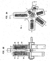
- Fig. 7a shows a front view of carriers 62, 63 which carry magnet arrays 71-75 and 81-85 respectively.
- Fig. 7b shows a side elevation view including a cross-section through planes indicated by lines A-A of the apparatus according to Fig. 7a and shows also a reaction vessel 13 positioned between carriers 62, 63.
- Carriers 62, 63 are connected to a shaft 64 supported by bearings 66, 67.
- a coupling element 65 connects carriers 62 and 63 with each other.
- Shaft 64 is connected to motor and mechanical transmission means (not shown) controlled by suitable control means for rotating and selectively positioning said carriers 62, 63 and thereby the arrays of magnet elements mounted on them at a plurality of predetermined angular positions with respect to reaction vessel 13 positioned between carriers 62, 63.
- Figures 7a, 7b and the figures following them show various angular positions of carriers 62, 63 and thereby various corresponding angular positions of the magnet arrays mounted thereon with respect to a reaction vessel 13 located at a predetermined stationary position between carriers 62, 63.
- Figures 7a, 7b and the figures following them illustrate in addition various processing steps carried out with respect to the contents of the reaction vessel 13.
- Step 1 Separation of magnetic particles (Figs. 7a, 7b)
- reaction vessel 13 contains a predetermined volume, e.g. 2.7 ml, of a lysing suspension 91 which contains biological cell material to be lysed and magnetic particles used as solid phase in a process for isolating nucleic acid contained in said cell material.
- Magnets 71 and 81 located on opposite sides of and close to the external surface of the side wall of reaction vessel 13 attract magnetic particles contained in lysing suspension 91 towards the inner surface of the side wall of reaction vessel 13. In this way the magnetic particles are grouped in layers deposited on opposite sides 92, 93 of the inner surface of the side wall of reaction vessel 13.
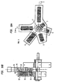
- Step 2 Aspiration of lysing suspension (Figs. 8a, 8b)
- Fig. 8a in this step carriers 62 and 63 have the same angular position (Pos. 1) as in step 1.
- Fig. 8b shows a cross-section through A-A in Fig. 8a .
- lysing suspension 91 is aspirated from reaction vessel 13 e.g. by means of an automatic pipettor, and as shown by Fig. 8b a layer of magnetic particles remains held on each of the opposite sides 92, 93 of the inner surface of the side wall of reaction vessel 13 by action of magnetic force exerted on those particles by magnets 71 and 81.
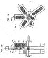
- Step 3 Dispensing of a first wash buffer (Figs. 9a, 9b)
- Fig. 9a in this step carriers 62 and 63 have the same angular position (Pos. 1) as in steps 1 and 2.
- Fig. 9b shows a cross-section through A-A in Fig. 9a .
- a predetermined volume, e.g. 2.8 ml, of a first wash buffer 94 is introduced in reaction vessel 13, and as shown by Fig. 9b layers of magnetic particles remain held on the inner surface of sides 92, 93 of the side wall of reaction vessel 13 by magnetic force exerted on those particles by magnets 71 and 81.
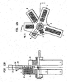
- Step 4 a Washing of magnetic particles (Figs. 10a, 10b)
- carriers 62 and 63 have the angular position (Pos. 3) shown by Fig. 10a.
- Fig. 10b shows a cross-section through C-C in Fig. 10a .
- magnets 72, 73 mounted on carrier 62 and located close to the external surface of the side wall of reaction vessel 13 hold the magnetic particles located on side 92 of the inner surface of the side wall of the reaction vessel 13 and attract the layer of magnetic particles located on the opposite side of the inner surface of the side wall of the reaction vessel 13.
- the latter particles are thereby moved through wash buffer 94 and join the magnetic particles of layer which lie on the opposite side 92 of the inner surface of the side wall of reaction vessel 13.
- Step 4b Washing of magnetic particles (Figs. 11a, 11b)
- Fig. 11b shows a cross-section through D-D in Fig. 11a .
- magnets 82, 83 mounted on carrier 63 and located close to the external surface of the side wall of reaction vessel 13 move the magnetic particles from side 92 of the inner surface of the side wall of the reaction vessel 13 to the opposite side 93 of the inner surface of the side wall of the reaction vessel 13.
- the magnetic particles are moved through the first wash buffer 94 and get thereby washed by this wash buffer.
- all magnetic particles are grouped in a layer on side 93 of the inner surface of the side wall of reaction vessel in a region close to magnets 82, 83.
- Steps 4a and 4b are repeated e.g. 3 times.
- Step 5 Separation of magnetic particles to low level (Figs. 12a, 12b)
- carriers 62 and 63 have the angular position (Pos. 5) shown by Fig. 12a.
- Fig. 12b shows a cross-section through E-E in Fig. 12a .
- a magnet 74 mounted on carrier 62 and located close to the lower part of the external surface of the side wall of reaction vessel 13 moves the magnetic particles from side 93 of the inner surface of the side wall of the reaction vessel 13 to the lower part of the opposite side 92 of the inner surface of the side wall of the reaction vessel 13.
- Step 6 Aspiration of wash buffer (Figs. 13a, 13b)
- Fig. 13a shows a cross-section through E-E in Fig. 13a .
- the first wash buffer 94 is aspirated from reaction vessel 13 e.g. by means of an automatic pipettor, and as shown by Fig. 13b a layer 95 of magnetic particles remains held on the lower part of side 92 of the inner surface of the side wall of reaction vessel 13 by action of magnetic force exerted on those particles by magnet 74 mounted on carrier 62.
- Step 7 Dispensing of wash buffer (Figs. 14a, 14b)
- Fig. 14a in this step carriers 62 and 63 have the same angular position (Pos. 5) as in steps 5 and 6.
- Fig. 14b shows a cross-section through E-E in Fig. 14a .
- a predetermined volume, e.g. 1 ml, of a second wash buffer 96 is introduced in reaction vessel 13, and as shown by Fig. 14b a layer 95 of magnetic particles remains held on the inner surface of sides 92 of the side wall of reaction vessel 13 by magnetic force exerted on those particles by magnet 74 mounted on carrier 62.
- Step 8a Washing of magnetic particles (Figs. 15a, 15b)
- Fig. 15b shows a cross-section through E-E in Fig. 15a .
- magnet 74 mounted on carrier 62 and located close to the external surface of the side wall of reaction vessel 13 holds the magnetic particles located on the lower part of side 92 of the inner surface of the side wall of the reaction vessel 13.
- all magnetic particles are grouped in a layer on side 92 of the inner surface of the side wall of reaction vessel in a region close to magnets 72, 73.
- Step 8b Washing of magnetic particles (Figs. 16a, 16b)
- Fig. 16b shows a cross-section through F-F in Fig. 16a .
- magnets 84, 85 mounted on carrier 63 and located close to the external surface of the side wall of reaction vessel 13 move the magnetic particles from the lower part of side 92 to the lower part of opposite side 93 of the inner surface of the side wall of the reaction vessel 13. The magnetic particles are moved through wash buffer 96 and get thereby washed by this wash buffer.
- all magnetic particles are grouped in a layer on the lower part of side 93 of the inner surface of the side wall of reaction vessel 13 in a region close to magnets 84, 85.
- Steps 8a and 8b are repeated e.g. 3 times.
- Step 9 Separation of magnetic particles to low level (Figs. 17a, 17b)
- carriers 62 and 63 have the angular position (Pos. 7) shown by Fig. 17a.
- Fig. 17b shows a cross-section through G-G in Fig. 17a .
- magnet 75 mounted on carrier 62 and located close to the external surface of the side wall of reaction vessel 13 moves the magnetic particles from the lower part of side 93 to the lowest part of the opposite side 92 of the inner surface of the side wall of the reaction vessel 13.
- Step 10 Aspiration of wash buffer (Figs. 18a, 18b)
- Fig. 18a in this step carriers 62 and 63 have the same angular position (Pos. 7) as in step 9.
- Fig. 18b shows a cross-section through G-G in Fig. 18a .
- the second wash buffer 94 is aspirated from reaction vessel 13 e.g. by means of an automatic pipettor, and as shown by Fig. 18b a layer 97 of magnetic particles remains held on the lowest part of side 92 of the inner surface of the side wall of reaction vessel 13 by action of magnetic force exerted on those particles by magnet 75 mounted on carrier 62.
- Step 11 Release of pellets (Figs. 19a, 19b)
- carriers 62 and 63 have the angular position (Pos. 6) shown by Fig. 19a.
- Fig. 19b shows a cross-section through F-F in Fig. 19a .
- magnets 84, 85 mounted on carrier 63 and located close to the external surface of the side wall of reaction vessel 13 release pellets which form layer 97 of magnetic particles by moving them from the lowest part of side 92 to the lowest part of side 93 of the inner surface of the side wall of the reaction vessel 13.
- Step 12 Addition of specimen diluent (Figs. 20a, 20b)
- carriers 62 and 63 have the angular position (Pos. 2) shown by Fig. 20a.
- Fig. 20b shows a cross-section through B-B in Fig. 20a .
- none of the magnets mounted on carriers 62 and 63 are located close to the external surface of the side wall of reaction vessel 13.
- a predetermined volume of specimen diluent 98 is dispensed into reaction vessel 13.
- Step 13 Mixing of magnet particles in reaction vessel (Figs. 21a, 21b)
- Fig. 21a shows a cross-section through B-B in Fig. 21a .
- tituration step by means of a so called tituration step the magnet particles present in the suspension contained in the reaction vessel 13 are thoroughly mixed by repeatedly aspirating said liquid from the vessel and redispensing it into the reaction vessel, e.g. by means of an automatic pipettor. This aspirating and redispensing is suggested in Fig. 21b by arrows pointing in opposite senses.
- reaction vessel contains a sample containing nucleic acid extracted from the biological cell material contained in the primary sample contained in reaction vessel 13 at the beginning of step 1.
- the nucleic acid sample present in reaction vessel 13 at the end of step 13 can be used e.g. for carrying out a polymerase chain reaction to amplify said nucleic acid.
- a common feature of the above described embodiments is that the means for selectively positioning the carrier or carriers which hold the magnet elements are adapted to position said carrier or carriers at predetermined angular positions which are selected according to a processing step to be carried out in that reaction vessel 13 and/or according to the amount of liquid in the reaction vessel 13.
- one or more magnet elements can be positioned close to the external surface of only one side of the reaction vessel 13, whereas in other of such predetermined angular positions one or more magnet elements can be positioned close to the external surface of the reaction vessel 13 on one side thereof and also close to the external surface of the reaction vessel on the opposite side thereof.
- at least one of the predetermined angular positions of the carrier or carriers of magnet elements can be a position at which no magnet element is located close to any external surface of the reaction vessel 13.
- these carriers have a common axis of rotation.
- the apparatus comprises a motor and mechanical transmission means controlled by suitable control means for rotating and selectively positioning said carrier 11 and thereby said array of magnet elements at a plurality of predetermined angular positions with respect to reaction vessel.
- control means preferably include means which perform the necessary control in response to commands provided by a process control unit which controls the processing of a sample-reagent mixture being processed in the reaction vessel. All control means just mentioned can be e.g. part of a control unit of an automatic apparatus.
- Such control means can include hardware and software means.
Landscapes
- Automatic Analysis And Handling Materials Therefor (AREA)
Description
- The invention relates to an apparatus for separating magnetic particles in suspension in a liquid contained in a reaction vessel of the type used in an automatic apparatus for processing biological samples, said processing including introducing a sample and one or more reagents into the reaction vessel.
- Magnetic particles are used as solid phase for performing diagnostic assays, e.g. immunoassays. Such assays comprise steps in which the magnetic particles are in suspension in a reaction solution contained in a reaction vessel. In other steps it is necessary to separate the magnetic particles from the liquid contained in the reaction vessel. In known apparatus this is usually done by attracting the magnetic particles to the walls of the reaction vessel by means of magnets positioned close to the outer side wall of the reaction vessel and by extracting the liquid from the reaction vessel by suitable means. This separation step is usually followed by a so called washing step in which the magnets are withdrawn to eliminate the magnetic force which held the magnetic particles on the inner wall of the reaction vessel during the previous separation step and fresh liquid pipetted into the reaction vessel in a way suitable to cause resuspension of the magnetic particles in the liquid contained in the reaction vessel.
- A disadvantage of known apparatuses for performing the above described separation step is that the relative movement of the magnet or magnets with respect to the reaction vessel is a translational movement and this has the disadvantage that the magnetic force exerted on the magnetic particles cannot be quickly removed and this causes an undesirable delay of the resuspension step. According to
WO-A-96/31781 - In known apparatuses for performing the above described separation step the magnet or magnets used therefor are positioned always at the same position. This has the disadvantage that the separation step is carried out properly and fast enough only for a limited variation range of the amount of the reaction solution contained in the reaction vessel. Outside that limited range the separation step is too slow and not quite proper.
-
DE-A-44 29 155 discloses an apparatus according to the preamble ofclaim 1.
DE-A-44 29 155 discloses a measuring system for performing luminometric series analyses on reaction components to be investigated and on theliquid samples 12 containing magnetizable carrier particles binding said components. The samples are transported in cuvette units of a multiple cuvette on a conveyor to a measuring station where the concentration of the target substance to be determined is determined by a luminescence measurement. To remove surplus reaction components that would distort measurement, multiple cuvettes are transported past a plurality of rotating permanent magnets. The lobe-shaped magnetic fields of those magnets penetrate cuvette units sequentially and from opposite wall areas. As a result the carrier particles are carried along spiral paths through the sample liquid and concentrated as pellets. The surplus reaction components separated from the carrier particles can then be removed in a rinsing and suction process.DE-A-44 29 155 describes in particular an embodiment wherein each permanent magnet is a double magnet that consists of two bar magnets that are preferably cylindrical, arranged parallel to one another with opposite polarity, with the double magnets being rotatable by means of a rotary drive around an axis of rotation that extends parallel to the magnetic axis of the magnets and perpendicular to the transport path of the conveyor. As a result, the magnetic fields generated by the rotating magnets penetrates the cuvette units in the form of a lobe, under whose influence the carrier particles move along long spiral paths and can accumulate pointwise as pellets on the cuvette walls. -
WO-A-93/08919 -
EP-A-691541 EP-A-691541 EP-A-691541 EP-A-691541 -
US-A-5770461 discloses arrangements wherein a rotatable single permanent magnet is positioned close to a vessel which has a vertical length axis and which contains a liquid in which magnetic particles are in suspension. In a first embodiment (Fig. 8 ) described inUS-A-5770461 , the magnetic axis of the permanent magnet is parallel to the vertical length axis of the vessel and the rotation axis of the permanent magnet is perpendicular to the vertical length axis of the vessel. In a second embodiment (Fig. 9 ) described inUS-A-5770461 , the magnetic axis of the permanent magnet is perpendicular to the vertical length axis of the vessel and the rotation axis of the permanent magnet is parallel to the vertical length axis of the vessel. -
WO-A-96/26011 - A main aim of the invention, therefore, is to provide an apparatus of the type indicated in the preamble of this description so devised as to overcome the above mentioned disadvantages of prior art apparatuses.
- A further aim of the invention is to provide an apparatus of the type indicated in the preamble which is in addition suitable for performing not only the above described separation step, but also the washing step.
- According to the invention, the above mentioned aims are attained with an apparatus according to
claim 1. Preferred embodiments are defined byclaims 2 to 6. - The main advantage of the apparatus according to the invention as compared with the prior art is that it makes possible to obtain a fast separation of magnetic particles contained in suspension in a reaction solution contained in a reaction vessel. This fast separation being obtained by rapid positioning of magnets close to the reaction vessel and at a plurality of selected heights with respect to the bottom of the reaction vessel, the height at which a magnet is positioned at a given point of time being selected according to a processing step to be carried out in the reaction vessel and/or according to the amount of reaction solution contained in the reaction vessel. This makes possible optimum adaptation of magnetic particle separation step to the process step being carried out in the reaction vessel.
- A further advantage of the apparatus according to the invention is that it also makes possible rapid removal of magnets positioned close to the reaction vessel during a separation step. This rapid removal makes possible to reduce the time interval necessary to obtain a resuspension of the magnetic particles in liquid contained in the reaction vessel.
- A further advantage of the apparatus according to the invention is that the combined effect of magnets positioned on opposite sides of a reaction vessel makes possible to obtain a particularly fast separation of magnetic particles contained in suspension in a reaction solution contained in a reaction vessel, and that such a fast separation is obtained even if the width of this vessel is above the average.
- A further advantage of the apparatus according to the invention is that it makes possible to carry out a washing step, that is a washing of the magnetic particles in suspension in a liquid, e.g. water, contained in a reaction vessel, by alternatively positioning a magnet or an array of magnet elements either on one side of the vessel or on the opposite side of the vessel, and thereby causing migration of the magnetic particles through the liquid from one side of the vessel to the opposite side thereof, the sense of this migration being reversed by changing the side on which a magnet is positioned close to the vessel.
- Another preferred embodiment of the apparatus according to the invention is characterized in that each of the magnet elements of said array or arrays of magnet elements comprises one or more magnets having the same width and the same azimuthal position on the carrier of the array.
- A further preferred embodiment of the apparatus according to the invention is characterized in that the axis of rotation of the carrier, respectively of each of the carriers, intersects with the length axis of the reaction vessel at a point located below the bottom of the reaction vessel.
- The apparatus according to the invention comprises a first and a second rotatable carrier and is characterized in that the carriers have a common axis of rotation.
- A further preferred embodiment of the apparatus according to the invention is characterized in that said means for selectively positioning said carrier or carriers are apt to position said carrier or carriers at predetermined angular positions which are selected according to a processing step to be carried out in that reaction vessel and/or according to the amount of liquid in the reaction vessel.
- A further preferred embodiment of the apparatus according to the invention is characterized in that said plurality of predetermined angular positions include one position at which no magnet element of said array or arrays of magnet elements is located close to any external surface of the reaction vessel.
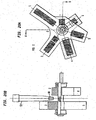
- Examples of embodiments of an apparatus according to the invention are described below with reference to the accompanying drawings wherein:
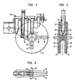
- Fig. 1
- is a schematic front view of an example of an apparatus similar to the one of the invention.
- Fig. 2
- is a side elevation of the apparatus according to
Fig. 1 . - Fig. 3
- is a plan view of the apparatus according to
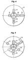
Fig. 1 . - Fig. 4
- is a front view of a first embodiment of an array of magnet elements held by
carrier 12 inFig. 1 . - Fig. 5
- is a front view of a second example of an array of magnet elements held by
carrier 12 inFig. 1 . - Fig. 6
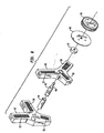
- is an exploded view of magnet array carriers of an apparatus according to the invention described as a first embodiment.
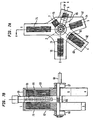
- Fig. 7a
- shows a front view of an apparatus according to the invention described as a second embodiment.
- Fig. 7b
- shows a side elevation view including a cross-section through planes indicated by lines A-A of the apparatus according to
Fig. 7a and shows also areaction vessel 13. -
Figures 8a and 8b , etc. up toFigures 21a and 21b show the carriers of arrays of magnet elements shown byFigures 7a and 7b in a plurality of angular positions and also illustrate different processing steps carried out in thereaction vessel 13. - Several embodiments of apparatuses are described hereinafter. These embodiments comprise each two rotatable carriers of magnet arrays.
- An example of an apparatus similar to the one of the invention is shown by
Figures 1 to 4 and is described hereinafter as an example not covered by the invention. This figures show an apparatus for separating magnet particles in suspension in a liquid contained in areaction vessel 13 of the type used in an automatic apparatus for processing biological samples. Such a processing includes introduction of a sample and one or more reagents intoreaction vessel 13. The apparatus shown byFigures 1 to 4 comprises afirst carrier 11 holding a first array of magnet elements 14-19.Carrier 11 is rotatable about arotation axis 51. - As shown by
Fig. 1 . the first array of magnet elements 14-19 comprises afirst magnet element 14 and at least asecond magnet element 15. These magnet elements are positioned on thecarrier 11 at different distances from therotation axis 51. Some of the magnet elements 14-19 lie on the same radius,e.g. magnet elements e.g. magnet element 14 andmagnet element 15. - The
carrier 11 and the array of magnet elements 14-19 are so configured and dimensioned that by rotation ofcarrier 11 one or more of the magnet elements of the first array of magnet elements 14-19 can be positioned close to the external surface of the side wall of thereaction vessel 13 on one side thereof. - The apparatus further comprises a motor and mechanical transmission means controlled by suitable control means for rotating and selectively positioning said
carrier 11 and thereby said array of magnet elements 14-19 at a plurality of predetermined angular positions with respect toreaction vessel 13. - The apparatus further comprises a
second carrier 12 holding a second array of magnet elements 24-29 shown byFig. 4 .Carrier 12 is rotatable about arotation axis 52. - The above description of
carrier 11 and array of magnet elements 14-19 also applies tocarrier 12 and array of magnet elements 24-29, because both arrays of magnet elements are symmetrically arranged with respect to the longitudinal symmetry axis of reaction vessel, so that for each angular position ofcarriers reaction vessel 13. -
Carriers - Each of the magnet elements of the arrays of magnet elements 14-19 or 24-29 comprises one or more magnets having preferably the same width and the same azimuthal position on the carrier of the array.
- The
axis 51 of rotation ofcarrier 11 and theaxis 52 of rotation ofcarrier 12 intersect with the length axis ofreaction vessel 13 at a point located below the bottom ofreaction vessel 13. - In the example shown by
Figures 1 to 4 , the axis ofrotation carriers reaction vessel 13 is part of a processing unit having a configuration that makes suitable to have such an angle between therotation axis carriers - A second example of an apparatus is described hereinafter with reference to
Fig. 5 as an example not covered by the invention. This second example is similar to the one described with reference toFigures 1 to 4 , but differs therefrom in that it comprises one or two carriers on each of which an array of magnets is mounted which differs from the arrays of magnets described with reference toFigures 1-4 . A preferred array of magnets for this second example of the apparatus is array of magnets 32-39 mounted on acarrier 31 as shown inFig. 5 . - A first embodiment of an apparatus according to the invention comprises magnet arrays shown by
Fig. 6 . The exploded view shown by this Figure shows afirst carrier 42 which carries an array ofmagnet elements second carrier 43 which carries an array ofmagnet elements Carriers driving wheel 49 by means ofcoupling elements ring 47 and adisk 48. Couplingelement 45 includes ashaft 46 driven by drivingwheel 49. Drivingwheel 49 is connected to a motor and suitable control means not shown inFig. 6 . By means of such motor and control meanscarriers carrier 42 and/orcarrier 43 close to the external surface of the side wall of a reaction vessel positioned betweencarriers - An apparatus according to the invention is described hereinafter with reference to
Figures 7a, 7b ,8a, 8b , etc. up to 20a, 20b as a second embodiment. -
Fig. 7a shows a front view ofcarriers Fig. 7b shows a side elevation view including a cross-section through planes indicated by lines A-A of the apparatus according toFig. 7a and shows also areaction vessel 13 positioned betweencarriers -
Carriers shaft 64 supported bybearings carriers Shaft 64 is connected to motor and mechanical transmission means (not shown) controlled by suitable control means for rotating and selectively positioning saidcarriers reaction vessel 13 positioned betweencarriers -
Figures 7a, 7b and the figures following them show various angular positions ofcarriers reaction vessel 13 located at a predetermined stationary position betweencarriers Figures 7a, 7b and the figures following them illustrate in addition various processing steps carried out with respect to the contents of thereaction vessel 13. - Such a use is described hereinafter for carrying a process to isolate a nucleic acid from biological cell material with the fourth embodiment of an apparatus according to the invention described above with reference to
Figures 7a and 7b . Such a process comprises the following steps illustrated by the Figures indicated between parentheses: - In this
step carriers Fig. 7a. Fig. 7b shows a cross-section through A-A inFig. 7a . As shown byFig. 7b ,reaction vessel 13 contains a predetermined volume, e.g. 2.7 ml, of a lysingsuspension 91 which contains biological cell material to be lysed and magnetic particles used as solid phase in a process for isolating nucleic acid contained in said cell material.Magnets reaction vessel 13 attract magnetic particles contained in lysingsuspension 91 towards the inner surface of the side wall ofreaction vessel 13. In this way the magnetic particles are grouped in layers deposited onopposite sides reaction vessel 13. - As shown by
Fig. 8a , in thisstep carriers step 1.Fig. 8b shows a cross-section through A-A inFig. 8a . In thisstep 2 lysingsuspension 91 is aspirated fromreaction vessel 13 e.g. by means of an automatic pipettor, and as shown byFig. 8b a layer of magnetic particles remains held on each of theopposite sides reaction vessel 13 by action of magnetic force exerted on those particles bymagnets - As shown by
Fig. 9a , in thisstep carriers steps Fig. 9b shows a cross-section through A-A inFig. 9a . A predetermined volume, e.g. 2.8 ml, of afirst wash buffer 94 is introduced inreaction vessel 13, and as shown byFig. 9b layers of magnetic particles remain held on the inner surface ofsides reaction vessel 13 by magnetic force exerted on those particles bymagnets - In this
step carriers Fig. 10a. Fig. 10b shows a cross-section through C-C inFig. 10a . As shown byFig. 10b , in thisstep 4a magnets carrier 62 and located close to the external surface of the side wall ofreaction vessel 13 hold the magnetic particles located onside 92 of the inner surface of the side wall of thereaction vessel 13 and attract the layer of magnetic particles located on the opposite side of the inner surface of the side wall of thereaction vessel 13. The latter particles are thereby moved throughwash buffer 94 and join the magnetic particles of layer which lie on theopposite side 92 of the inner surface of the side wall ofreaction vessel 13. In this way the magnetic particles of layer which are moved fromside 93 to theopposite side 92 get washed bywash buffer 94. At the end of this step 4a all magnetic particles are grouped in a layer onside 92 of the inner surface of the side wall of reaction vessel in a region close tomagnets - In this
step carriers Fig. 11a. Fig. 11b shows a cross-section through D-D inFig. 11a . As shown byFig. 11b , in thisstep 4b magnets carrier 63 and located close to the external surface of the side wall ofreaction vessel 13 move the magnetic particles fromside 92 of the inner surface of the side wall of thereaction vessel 13 to theopposite side 93 of the inner surface of the side wall of thereaction vessel 13. The magnetic particles are moved through thefirst wash buffer 94 and get thereby washed by this wash buffer. At the end of this step 4b all magnetic particles are grouped in a layer onside 93 of the inner surface of the side wall of reaction vessel in a region close tomagnets - Steps 4a and 4b are repeated e.g. 3 times.
- In this
step carriers Fig. 12a. Fig. 12b shows a cross-section through E-E inFig. 12a . As shown byFig. 12b , in this step 5 amagnet 74 mounted oncarrier 62 and located close to the lower part of the external surface of the side wall ofreaction vessel 13 moves the magnetic particles fromside 93 of the inner surface of the side wall of thereaction vessel 13 to the lower part of theopposite side 92 of the inner surface of the side wall of thereaction vessel 13. - As shown by
Fig. 13a , in thisstep carriers step 5.Fig. 13b shows a cross-section through E-E inFig. 13a . In thisstep 6 thefirst wash buffer 94 is aspirated fromreaction vessel 13 e.g. by means of an automatic pipettor, and as shown byFig. 13b alayer 95 of magnetic particles remains held on the lower part ofside 92 of the inner surface of the side wall ofreaction vessel 13 by action of magnetic force exerted on those particles bymagnet 74 mounted oncarrier 62. - As shown by
Fig. 14a , in thisstep carriers steps Fig. 14b shows a cross-section through E-E inFig. 14a . In this step 7 a predetermined volume, e.g. 1 ml, of asecond wash buffer 96 is introduced inreaction vessel 13, and as shown byFig. 14b alayer 95 of magnetic particles remains held on the inner surface ofsides 92 of the side wall ofreaction vessel 13 by magnetic force exerted on those particles bymagnet 74 mounted oncarrier 62. - In this
step carriers Fig. 15a. Fig. 15b shows a cross-section through E-E inFig. 15a . As shown byFig. 15b , in thisstep 8a magnet 74 mounted oncarrier 62 and located close to the external surface of the side wall ofreaction vessel 13 holds the magnetic particles located on the lower part ofside 92 of the inner surface of the side wall of thereaction vessel 13. At the end of this step 8a all magnetic particles are grouped in a layer onside 92 of the inner surface of the side wall of reaction vessel in a region close tomagnets - In this
step carriers Fig. 16a. Fig. 16b shows a cross-section through F-F inFig. 16a . As shown byFig. 16b , in thisstep 8b magnets carrier 63 and located close to the external surface of the side wall ofreaction vessel 13 move the magnetic particles from the lower part ofside 92 to the lower part ofopposite side 93 of the inner surface of the side wall of thereaction vessel 13. The magnetic particles are moved throughwash buffer 96 and get thereby washed by this wash buffer. At the end of this step 8b all magnetic particles are grouped in a layer on the lower part ofside 93 of the inner surface of the side wall ofreaction vessel 13 in a region close tomagnets - Steps 8a and 8b are repeated e.g. 3 times.
- In this
step carriers Fig. 17a. Fig. 17b shows a cross-section through G-G inFig. 17a . As shown byFig. 17b , in this step 9magnet 75 mounted oncarrier 62 and located close to the external surface of the side wall ofreaction vessel 13 moves the magnetic particles from the lower part ofside 93 to the lowest part of theopposite side 92 of the inner surface of the side wall of thereaction vessel 13. - As shown by
Fig. 18a , in thisstep carriers Fig. 18b shows a cross-section through G-G inFig. 18a . In this step 10 thesecond wash buffer 94 is aspirated fromreaction vessel 13 e.g. by means of an automatic pipettor, and as shown byFig. 18b alayer 97 of magnetic particles remains held on the lowest part ofside 92 of the inner surface of the side wall ofreaction vessel 13 by action of magnetic force exerted on those particles bymagnet 75 mounted oncarrier 62. - In this
step carriers Fig. 19a. Fig. 19b shows a cross-section through F-F inFig. 19a . As shown byFig. 19b , in thisstep 11magnets carrier 63 and located close to the external surface of the side wall ofreaction vessel 13 release pellets which formlayer 97 of magnetic particles by moving them from the lowest part ofside 92 to the lowest part ofside 93 of the inner surface of the side wall of thereaction vessel 13. - In this
step carriers Fig. 20a. Fig. 20b shows a cross-section through B-B inFig. 20a . As shown byFig. 20b , in thisstep 12 none of the magnets mounted oncarriers reaction vessel 13. A predetermined volume ofspecimen diluent 98 is dispensed intoreaction vessel 13. - As shown by
Fig. 21a , in thisstep carriers step 12.Fig. 21b shows a cross-section through B-B inFig. 21a . In thisstep 13, by means of a so called tituration step the magnet particles present in the suspension contained in thereaction vessel 13 are thoroughly mixed by repeatedly aspirating said liquid from the vessel and redispensing it into the reaction vessel, e.g. by means of an automatic pipettor. This aspirating and redispensing is suggested inFig. 21b by arrows pointing in opposite senses. At the end ofstep 13 reaction vessel contains a sample containing nucleic acid extracted from the biological cell material contained in the primary sample contained inreaction vessel 13 at the beginning ofstep 1. The nucleic acid sample present inreaction vessel 13 at the end ofstep 13 can be used e.g. for carrying out a polymerase chain reaction to amplify said nucleic acid. - A common feature of the above described embodiments is that the means for selectively positioning the carrier or carriers which hold the magnet elements are adapted to position said carrier or carriers at predetermined angular positions which are selected according to a processing step to be carried out in that
reaction vessel 13 and/or according to the amount of liquid in thereaction vessel 13. - As described above with reference to
embodiments reaction vessel 13, whereas in other of such predetermined angular positions one or more magnet elements can be positioned close to the external surface of thereaction vessel 13 on one side thereof and also close to the external surface of the reaction vessel on the opposite side thereof. As described above in particular with reference toembodiment 2 at least one of the predetermined angular positions of the carrier or carriers of magnet elements can be a position at which no magnet element is located close to any external surface of thereaction vessel 13. - In all above described embodiments of an apparatus:
- each of the magnet elements of said array or arrays of magnet elements preferably comprises one or more magnets having the same width and the same azimuthal position on the carrier of the array, and
- the axis of rotation of the carrier, respectively of each of the carriers, preferably intersects with the length axis of the reaction vessel at a point located below the bottom of the reaction vessel.
- In embodiments comprising two carriers of arrays of magnet elements, these carriers have a common axis of rotation.
- In all above described embodiments of an apparatus, the apparatus comprises a motor and mechanical transmission means controlled by suitable control means for rotating and selectively positioning said
carrier 11 and thereby said array of magnet elements at a plurality of predetermined angular positions with respect to reaction vessel. Such control means preferably include means which perform the necessary control in response to commands provided by a process control unit which controls the processing of a sample-reagent mixture being processed in the reaction vessel. All control means just mentioned can be e.g. part of a control unit of an automatic apparatus. Such control means can include hardware and software means.
Claims (6)
- Apparatus for separating magnetic particles in suspension in a liquid, said apparatus including(a) a first rotatable carrier (62) holding a first array of magnet elements,(b) a second rotatable carrier (63) offset from said first carrier (62) and holding a second array of magnet elements each of said first and second arrays of magnet elements comprising a first magnet element and at least a second magnet element, said apparatus being characterized in that
said first and second carriers (62, 63) define a region therebetween and are rotatable about a rotation axis common to both carriers,
in that said first and second magnet elements are positioned on the carrier at different distances from the rotation axis common to said carriers and the centers of the first magnet element and of the at least second magnet element lie on radii located at different azimuth angles,
and characterised in that said apparatus further comprises(c) an elongated reaction vessel (13) located in said region, said reaction vessel having a length axis and containing suspended magnetic particles, said length axis lying in a plane that is normal to the rotation axis of said first and second carriers (62, 63), and(d) means for selectively positioning said carriers (62, 63) and thereby said first and second arrays of magnet elements at a plurality of predetermined angular positions measured on a plane normal to said rotation axis of said carriers (62, 63),in some angular positions of said first and second carriers (62, 63) at least one of the magnet elements on said first carrier (62) is disposed across said region from a corresponding one of the magnet elements on said second carrier (63), and
in some other angular positions of said first and second carriers (62, 63) at least one other one of the magnet elements on said first carrier (62) and at least one other one of the magnet elements on said second carrier (63) being asymmetrically positioned with respect to the reaction vessel. - An apparatus according to claim 1, characterized in that each of said first and second arrays of magnet elements comprises
a first magnet element mounted on said carrier (42 respectively 43) at a first azimuthal position, the center of said first magnet lying at a first distance from the center of said carrier, no other magnet being mounted on said carrier (42, 43) at said first azimuthal position, and
a second magnet element mounted on said carrier (42 respectively 43) at a second azimuthal position, the center of said second magnet lying at a second distance from the center of said carrier, said second distance being different from said first distance, no other magnet being mounted on said carrier (42, 43) at said second azimuthal position - An apparatus according to any of the preceding claims, characterized in that each of the magnet elements of said first and second arrays of magnet elements comprises one or more magnets having the same width and the same azimuthal position on the carrier of the array.
- An apparatus according to claim 1, characterized in that the axis of rotation of said first carrier (62) and the axis of rotation of said second carrier (63) intersects with the length axis of the reaction vessel (13) at a point located below the bottom of the reaction vessel.
- An apparatus according to claim 1, charaterized in that said means for selectively positioning said first and second carriers (62, 63) at predetermined angular positions are adapted for positioning said carriers (62, 63) at angular positions which are selected according to a processing step to be carried out in that reaction vessel (13) and/or according to the amount of liquid in the reaction vessel.
- An apparatus according to claim 1, characterized in that said plurality of predetermined angular positions include one position at which no magnet element is located close to any external surface of the reaction vessel (13).
Priority Applications (2)
| Application Number | Priority Date | Filing Date | Title |
|---|---|---|---|
| EP06013082A EP1712921A2 (en) | 1997-09-29 | 1998-07-08 | Apparatus for separating magnetic particles |
| EP98810649A EP0905520B1 (en) | 1997-09-29 | 1998-07-08 | Apparatus for separating magnetic particles |
Applications Claiming Priority (3)
| Application Number | Priority Date | Filing Date | Title |
|---|---|---|---|
| EP97116857 | 1997-09-29 | ||
| EP97116857 | 1997-09-29 | ||
| EP98810649A EP0905520B1 (en) | 1997-09-29 | 1998-07-08 | Apparatus for separating magnetic particles |
Related Child Applications (1)
| Application Number | Title | Priority Date | Filing Date |
|---|---|---|---|
| EP06013082A Division EP1712921A2 (en) | 1997-09-29 | 1998-07-08 | Apparatus for separating magnetic particles |
Publications (2)
| Publication Number | Publication Date |
|---|---|
| EP0905520A1 EP0905520A1 (en) | 1999-03-31 |
| EP0905520B1 true EP0905520B1 (en) | 2008-03-26 |
Family
ID=26145804
Family Applications (2)
| Application Number | Title | Priority Date | Filing Date |
|---|---|---|---|
| EP06013082A Withdrawn EP1712921A2 (en) | 1997-09-29 | 1998-07-08 | Apparatus for separating magnetic particles |
| EP98810649A Expired - Lifetime EP0905520B1 (en) | 1997-09-29 | 1998-07-08 | Apparatus for separating magnetic particles |
Family Applications Before (1)
| Application Number | Title | Priority Date | Filing Date |
|---|---|---|---|
| EP06013082A Withdrawn EP1712921A2 (en) | 1997-09-29 | 1998-07-08 | Apparatus for separating magnetic particles |
Country Status (1)
| Country | Link |
|---|---|
| EP (2) | EP1712921A2 (en) |
Cited By (2)
| Publication number | Priority date | Publication date | Assignee | Title |
|---|---|---|---|---|
| US7601491B2 (en) | 2003-02-06 | 2009-10-13 | Becton, Dickinson And Company | Pretreatment method for extraction of nucleic acid from biological samples and kits therefor |
| US8361316B2 (en) | 1995-02-21 | 2013-01-29 | Sigris Research, Inc. | Device for mixing and separation of magnetic particles |
Families Citing this family (11)
| Publication number | Priority date | Publication date | Assignee | Title |
|---|---|---|---|---|
| US20030127396A1 (en) * | 1995-02-21 | 2003-07-10 | Siddiqi Iqbal Waheed | Apparatus and method for processing magnetic particles |
| US6672458B2 (en) | 2000-05-19 | 2004-01-06 | Becton, Dickinson And Company | System and method for manipulating magnetically responsive particles fluid samples to collect DNA or RNA from a sample |
| DE10156790A1 (en) * | 2001-11-19 | 2003-06-18 | Chemagen Biopolymer Technologi | Device and method for treating magnetic particles |
| US7718072B2 (en) | 2002-04-26 | 2010-05-18 | Abbott Laboratories | Structure and method for handling magnetic particles in biological assays |
| RU2004137103A (en) | 2002-05-17 | 2005-11-20 | Бектон, Дикинсон Энд Компани (Us) | AUTOMATED SYSTEM FOR ISOLATION, AMPLIFICATION AND IDENTIFICATION OF NUCLEOTIDE TARGETS-TARGETS |
| JP2008544277A (en) * | 2005-06-23 | 2008-12-04 | コーニンクレッカ フィリップス エレクトロニクス エヌ ヴィ | Device for moving magnetic particles |
| DE102005039175A1 (en) | 2005-08-18 | 2007-02-22 | Qiagen Gmbh | Apparatus and method for separating magnetic particles from a liquid |
| DE102007045474A1 (en) | 2007-09-21 | 2009-04-02 | Qiagen Gmbh | Apparatus and method for treating liquids with magnetic particles |
| EP2068143A1 (en) * | 2007-12-07 | 2009-06-10 | Roche Diagnostics GmbH | Manipulation of magnetic micro particles in a high pressure fluid system and extraction process |
| US8337705B2 (en) | 2008-12-04 | 2012-12-25 | Roche Diagnostics Operations, Inc. | Manipulation of magnetic microparticles in a high pressure liquid system and extraction process |
| JP6431522B2 (en) | 2013-03-15 | 2018-11-28 | アボツト・モレキユラー・インコーポレイテツド | One-step method for purification of nucleic acids |
Citations (2)
| Publication number | Priority date | Publication date | Assignee | Title |
|---|---|---|---|---|
| WO1996026011A1 (en) * | 1995-02-21 | 1996-08-29 | Siddiqi Iqbal W | Apparatus and method for mixing and separation employing magnetic particles |
| US5770461A (en) * | 1994-09-02 | 1998-06-23 | Hitachi, Ltd. | Method and apparatus for separation of solid supports and liquid phase |
Family Cites Families (7)
| Publication number | Priority date | Publication date | Assignee | Title |
|---|---|---|---|---|
| BE792113A (en) * | 1971-12-13 | 1973-05-30 | Technicon Instr | MIXER FOR LIQUIDS CONTAINING MAGNETIC PARTICLES |
| WO1993008919A1 (en) * | 1991-11-08 | 1993-05-13 | Envimag B.V. | Magnetic disc separator |
| US5670329A (en) * | 1993-05-28 | 1997-09-23 | Cardiovascular Diagnostics, Inc. | Method and analytical system for performing fibrinogen assays accurately, rapidly and simply using a rotating magnetic field |
| DE4423878A1 (en) * | 1994-07-07 | 1996-01-11 | Boehringer Mannheim Gmbh | Device and method for separating magnetic microparticles |
| DE4429155A1 (en) * | 1994-08-17 | 1996-02-22 | Hans Schiesl | Measuring arrangement and method for carrying out luminometric series analyzes as well as multiple cuvette for taking liquid samples therefor |
| US5599501A (en) * | 1994-11-10 | 1997-02-04 | Ciba Corning Diagnostics Corp. | Incubation chamber |
| DE19512368A1 (en) * | 1995-04-01 | 1996-10-02 | Boehringer Mannheim Gmbh | Nucleic acid release and isolation system |
-
1998
- 1998-07-08 EP EP06013082A patent/EP1712921A2/en not_active Withdrawn
- 1998-07-08 EP EP98810649A patent/EP0905520B1/en not_active Expired - Lifetime
Patent Citations (2)
| Publication number | Priority date | Publication date | Assignee | Title |
|---|---|---|---|---|
| US5770461A (en) * | 1994-09-02 | 1998-06-23 | Hitachi, Ltd. | Method and apparatus for separation of solid supports and liquid phase |
| WO1996026011A1 (en) * | 1995-02-21 | 1996-08-29 | Siddiqi Iqbal W | Apparatus and method for mixing and separation employing magnetic particles |
Cited By (3)
| Publication number | Priority date | Publication date | Assignee | Title |
|---|---|---|---|---|
| US8361316B2 (en) | 1995-02-21 | 2013-01-29 | Sigris Research, Inc. | Device for mixing and separation of magnetic particles |
| US7601491B2 (en) | 2003-02-06 | 2009-10-13 | Becton, Dickinson And Company | Pretreatment method for extraction of nucleic acid from biological samples and kits therefor |
| US7727727B2 (en) | 2003-02-06 | 2010-06-01 | Becton Dickinson And Company | Pretreatment method for extraction of nucleic acid from biological samples and kits therefor |
Also Published As
| Publication number | Publication date |
|---|---|
| EP0905520A1 (en) | 1999-03-31 |
| EP1712921A2 (en) | 2006-10-18 |
Similar Documents
| Publication | Publication Date | Title |
|---|---|---|
| US6579453B1 (en) | Apparatus for separating magnetic particles | |
| US11885799B2 (en) | Centrifuge including a magnetic element and method for centrifuging a reaction vessel unit | |
| EP0763739B1 (en) | Method and apparatus for liquid treatment utilizing dispenser | |
| JP4856831B2 (en) | Apparatus and method for mixing magnetic particles with a fluid | |
| EP0358948B1 (en) | Method for automatically processing magnetic solid phase reagents | |
| US5705062A (en) | Analytical device for separating magnetic microparticles from suspensions | |
| EP2500076B1 (en) | Structure and method for handling magnetic particles in biological assays | |
| EP2290365A1 (en) | Analyzer using magnetic particles | |
| EP0905520A1 (en) | Apparatus for separating magnetic particles | |
| US6150182A (en) | Method for separation of components in a biochemical reaction utilizing a combination of magnetic and centrifugal processes | |
| US8323507B2 (en) | Device and method for the elimination of magnetic particles from a liquid | |
| US6872360B1 (en) | Centrifuging device for laboratory analyzer | |
| JP5260231B2 (en) | Magnetic particle solution stirring device | |
| US20080003143A1 (en) | Device and method for handling reaction components | |
| CN117242351A (en) | Systems and methods for pooling samples for high-throughput analysis |
Legal Events
| Date | Code | Title | Description |
|---|---|---|---|
| PUAI | Public reference made under article 153(3) epc to a published international application that has entered the european phase |
Free format text: ORIGINAL CODE: 0009012 |
|
| AK | Designated contracting states |
Kind code of ref document: A1 Designated state(s): DE FR IT |
|
| AX | Request for extension of the european patent |
Free format text: AL;LT;LV;MK;RO;SI |
|
| 17P | Request for examination filed |
Effective date: 19990612 |
|
| AKX | Designation fees paid |
Free format text: DE FR IT |
|
| GRAP | Despatch of communication of intention to grant a patent |
Free format text: ORIGINAL CODE: EPIDOSNIGR1 |
|
| GRAS | Grant fee paid |
Free format text: ORIGINAL CODE: EPIDOSNIGR3 |
|
| GRAA | (expected) grant |
Free format text: ORIGINAL CODE: 0009210 |
|
| AK | Designated contracting states |
Kind code of ref document: B1 Designated state(s): DE FR IT |
|
| REF | Corresponds to: |
Ref document number: 69839294 Country of ref document: DE Date of ref document: 20080508 Kind code of ref document: P |
|
| ET | Fr: translation filed | ||
| PLBE | No opposition filed within time limit |
Free format text: ORIGINAL CODE: 0009261 |
|
| STAA | Information on the status of an ep patent application or granted ep patent |
Free format text: STATUS: NO OPPOSITION FILED WITHIN TIME LIMIT |
|
| 26N | No opposition filed |
Effective date: 20081230 |
|
| PGFP | Annual fee paid to national office [announced via postgrant information from national office to epo] |
Ref country code: FR Payment date: 20110727 Year of fee payment: 14 |
|
| PGFP | Annual fee paid to national office [announced via postgrant information from national office to epo] |
Ref country code: DE Payment date: 20110729 Year of fee payment: 14 |
|
| PGFP | Annual fee paid to national office [announced via postgrant information from national office to epo] |
Ref country code: IT Payment date: 20110719 Year of fee payment: 14 |
|
| REG | Reference to a national code |
Ref country code: FR Ref legal event code: ST Effective date: 20130329 |
|
| PG25 | Lapsed in a contracting state [announced via postgrant information from national office to epo] |
Ref country code: DE Free format text: LAPSE BECAUSE OF NON-PAYMENT OF DUE FEES Effective date: 20130201 Ref country code: FR Free format text: LAPSE BECAUSE OF NON-PAYMENT OF DUE FEES Effective date: 20120731 |
|
| PG25 | Lapsed in a contracting state [announced via postgrant information from national office to epo] |
Ref country code: IT Free format text: LAPSE BECAUSE OF NON-PAYMENT OF DUE FEES Effective date: 20120708 |
|
| REG | Reference to a national code |
Ref country code: DE Ref legal event code: R119 Ref document number: 69839294 Country of ref document: DE Effective date: 20130201 |