EP0905478A2 - Wall thickness measurement method - Google Patents
Wall thickness measurement methodInfo
- Publication number
- EP0905478A2 EP0905478A2 EP98112493A EP98112493A EP0905478A2 EP 0905478 A2 EP0905478 A2 EP 0905478A2 EP 98112493 A EP98112493 A EP 98112493A EP 98112493 A EP98112493 A EP 98112493A EP 0905478 A2 EP0905478 A2 EP 0905478A2
- Authority
- EP
- European Patent Office
- Prior art keywords
- wall
- ultrasonic
- reflection
- medium
- thickness
- Prior art date
- Legal status (The legal status is an assumption and is not a legal conclusion. Google has not performed a legal analysis and makes no representation as to the accuracy of the status listed.)
- Withdrawn
Links
Images


Classifications
-
- G—PHYSICS
- G01—MEASURING; TESTING
- G01B—MEASURING LENGTH, THICKNESS OR SIMILAR LINEAR DIMENSIONS; MEASURING ANGLES; MEASURING AREAS; MEASURING IRREGULARITIES OF SURFACES OR CONTOURS
- G01B17/00—Measuring arrangements characterised by the use of infrasonic, sonic or ultrasonic vibrations
- G01B17/02—Measuring arrangements characterised by the use of infrasonic, sonic or ultrasonic vibrations for measuring thickness
Definitions
- the present invention relates to a method by which the Wall thickness determined using ultrasound can be.
- the path of ultrasound can be exactly traced. That means in particular, that the path lengths and the angles of the Sound level must be known.
- the path lengths can change however, e.g. B. by abrasion of the material on which the ultrasound is reflected, change. If by abrasion reduced wall thickness z. B. measured a flow tube the current path length can also be calculated. This is made possible by subsequent calibration, to maintain the required standard of accuracy.
- An ongoing Monitoring the wall thickness of a measuring tube also serves ensure that the required compressive strength the minimum required wall thickness is not undershot.
- a test head is used for ultrasonic wall thickness measurement used, which is attached to the pipe wall and after the Pulse echo method sends ultrasonic pulses into the pipe wall and receives the reflection signals. From the term between the transmission of the pulse and the reception time and off the known speed of sound, the thickness of the Calculate pipe wall.
- This method has the disadvantage that it the test head is an oscillatory system and the emitted ultrasound pulse is therefore not ideal has a limited course.
- the superimposition of reflections or of reflection and decay behavior can Make measurement difficult or even impossible. Problematic are mainly measurements on very thin walls.
- the object of the present invention is to provide a method for To specify wall thickness measurement, that is also simple and reliable can be used to measure thin walls.
- a wall the Thickness to be measured on both sides of media, e.g. B. from Liquids, surrounded. These media are chosen so that they have lower acoustic impedances than the acoustic ones Wall impedance.
- the tube is preferably left of flow through a liquid and attaches to the outside A test head with another liquid or another suitable medium ("flow fluid").
- the Flow fluid is in a container of the test head, which can be brought into contact with the pipe wall in such a way that between the liquid and the pipe wall either none or only a very thin partition that does not affect the measurement is available.
- the test head also has a Ultrasonic transducers, e.g. B. a piezoceramic, the ultrasound can transmit and preferably also receive. A generated ultrasound signal is coupled into the flow fluid and aligned to the pipe wall to be measured.
- the ultrasound is reflected on the material of the pipe wall (e.g. steel). Another reflection occurs on the inner tube wall. With a sufficiently long wave train ( burst ") there is a destructive superimposition of the reflected ultrasound signals if and only if the thickness of the tube wall is an integer multiple of half the wavelength of the ultrasound signal. If Z 1 denotes the impedance of the flow fluid in the test head, Z 2 denotes the impedance of the tube wall and with Z 3 the impedance of the measuring fluid flowing in the tube, then Z 2 >> Z 1 and Z 2 >> Z 3.
- a frequency of the ultrasound transducer is sought at which the reflection becomes minimal.
- the wavelength of the ultrasound in the material of the wall can be determined from the frequency, because the The speed of sound in the wall is equal to the product of the frequency and the wavelength in de r Wall: This wavelength then fulfills the condition of minimal reflection, so that the wall thickness can be determined from it. Since there are minimal reflections for different frequencies, the lowest frequency at which the minimal reflection occurs must be found. The easiest way to do this is when an approximate value for the wall thickness to be measured is already known.
- the impedance Z 1 of the flow fluid is advantageously chosen so that the change in reflection becomes as great as possible when the frequency of the reflection minimum is reached. This minimum is then particularly easy to recognize.
- other media e.g. B. also a solid if the medium has a lower acoustic impedance than the wall to be measured itself.
- the method according to the invention can also be used for measuring the wall thickness of test objects in a plunge pool, for. B. use as a quality control in a production process.
- the wall 1 of a tube is shown in cross section, in which a medium, e.g. B. a liquid as a measuring fluid is available. From the outside there is a pipe wall Test head with an ultrasonic transducer 3 and a container 4 which is a medium, here a liquid as an example, contains as flow fluid 5.
- the test head can also be fixed be mounted on the wall, e.g. B. for a continuous wall thickness measurement.
- an ultrasound pulse from the ultrasound transducer 3 onto the wall directed.
- This ultrasonic signal US is on the outer Surface 11 of the wall 1 and on the inner surface 12 the wall 1 reflected. From the ultrasonic signal US arises a reflection component R and a transmission component T.
- the ultrasonic impedance of liquids is generally in the range from 50 ⁇ 10 4 to 300 ⁇ 10 4 kg m / s. Exceptions like mercury are very rare.
- the impedance of steel is much higher at 4524 ⁇ 10 4 kg m / s. If a typical liquid is used in the flow and the thickness of a steel pipe is to be determined, the reflection of the ultrasound in the flow fluid 5 against the steel of the pipe wall 1 is first high (87.5 to 97.8% amplitude reflection). Only when a frequency of minimal reflection is set does the reflection of the ultrasound with respect to the liquid of the measuring fluid 2 come into play (-71 to +71% amplitude reflection, that is to say possibly even with a change of sign).
- the Measurement according to the invention is comparatively simple.
- the method according to the invention can, as shown in Figure 1 is, with only one ultrasonic transducer 3, which alternately is operated as a transmitter and as a receiver become. This is possible because it is enough for the measurement the piezoceramic provided for sound generation To excite the ultrasonic transducer with a sinus pulse (sinus burst).
- the pulse length is selected so that in the steady state State of the ultrasonic transducer can be measured.
- Corresponding must be a lead of the ultrasound signal US be set up so long that the wavefront of the Reflection component R only after the end of the transmission process arrives at the ultrasonic transducer. Therefore, the container is 4th of the test head, which contains the flow fluid 5, sufficient long to choose, as indicated in Figure 1.
- the Sound frequency of the ultrasonic transducer is controlled tracked until a minimum sound level is available (resonance vote).
- FIG 2 shows the cross section shown in Figure 1 is for a modified test head with two ultrasonic transducers, one of them as transmitter 3 and one as receiver 30 is used.
- the transmitter 3 in Continuous operation (CW, continues wave) are operated.
- the as Ultrasonic transducers used in receiver 30 then receive continuously the reflection component R of the ultrasonic signal US.
- the sound falls at an angle ⁇ to the vertical on the outer surface 11 of the wall 1.
- the wall thickness therefore, taking the cosine into account, this angle ⁇ calculated. It is easier if, according to FIG second ultrasonic transducers serving as receivers 31 or is attached in the opposite tube wall 10.
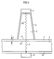
- FIG. 3 is in the preferred embodiment with two ultrasonic transducers used a probe that is similar the embodiment shown in Figure 1 is designed.
- minimal reflection is essentially only the transmission component T of the ultrasonic signal US available, which penetrates the measuring fluid 2 and into the receiver 31 arrives at the opposite tube wall 10.
- This Receiver 31 is preferably also a piezoceramic.
- the receiver can be in the wall or on the wall Wall inside or outside of the pipe. On the surfaces of the rear wall 10 of the tube occurring additional reflections are harmless for the measurements, if the tube wall has the same thickness all around.
- the frequency Since in the execution of the test head according to Figure 3 the Transmission component T is received, the frequency must be here of the transmitter 3 are tuned until the signal on Receiver 31 becomes maximum. Then the amount of reflection is minimal. Because with this arrangement with two ultrasonic transducers in contrast to the pulse mode, the transmission process is not interrupted must be the minimum of reflection with one greater accuracy can be determined. Attenuation of the ultrasound signal in the measuring fluid 2 affects the measurement not as long as the ultrasonic signal at the receiver 31 with a sufficient intensity arrives to the maximum of To be able to determine the transmission component T. They can also Impedances of the liquids in the flow (flow fluid 5) and be different in the tube (measuring fluid 2). The only requirement is that the jump in impedances between the flow fluid and the pipe wall is greater than the jump in impedances between the feed fluid and measuring fluid. Then the transmission frequency of the maximum of the transmission share can be found.
- the method according to the invention is also suitable for the Thickness of a wall z. B. to determine a flat test object.
- the measurement can be made in a plunge pool be made in which a wall is immersed.
- Figure 4 shows an arrangement of a sensor suitable for this measurement Dip tank 6, which is filled with a liquid 7.
- a Wall 8 whose thickness d is to be measured, is in the liquid immersed, and an ultrasonic signal US from an ultrasonic transducer 32 aimed at the wall as a transmitter.
- Another Ultrasonic transducer 33 as the receiver detects the wall 8 penetrating transmission component T of the ultrasonic signal. Since on both sides of the immersed wall 8 same liquid, the reflection disappears when Reaching the associated frequency under ideal conditions completely or at least assumes a minimum.
- This appearance can also be the maximum of the transmission component T in the arrangement shown with two ultrasonic transducers be measured. Instead, it is possible to use only one ultrasound transducer to use and the minimum of the reflection portion to be determined in the burst mode of the ultrasonic transducer.
- the inventive method allows simple conventional equipment a very accurate measurement of the thickness of walls. Preferably, the lowest frequency leading to a minimum of the reflection portion heard, voted.
- the process can be carried out with particularly little Carry out effort if only an ultrasonic transducer is used. If greater measurement accuracy is required , the process is preferably carried out with two separate ones Ultrasonic transducers for sending and receiving executed.
Landscapes
- Physics & Mathematics (AREA)
- General Physics & Mathematics (AREA)
- Length Measuring Devices Characterised By Use Of Acoustic Means (AREA)
Abstract
Description
Die vorliegende Erfindung betrifft ein Verfahren, mit dem die Dicke von Wandungen unter Verwendung von Ultraschall bestimmt werden kann.The present invention relates to a method by which the Wall thickness determined using ultrasound can be.
Bei der industriellen Durchflußmessung mit Ultraschall muß der Weg des Ultraschalls genau nachvollziehbar sein. Das bedeutet insbesondere, daß die Weglängen und die Winkel der Schallspiegel bekannt sein müssen. Die Weglängen können sich jedoch z. B. durch Abrasion des Materials, an dem der Ultraschall reflektiert wird, verändern. Wenn die durch Abrasion verminderte Wanddicke z. B. eines Durchflußrohres gemessen werden kann, kann auch die aktuelle Weglänge berechnet werden. Das ermöglicht dann durch nachträgliche Kalibrierung, den geforderten Genauigkeitsstandard zu halten. Eine laufende Überwachung der Wanddicke eines Meßrohres dient auch dazu, sicherzustellen, daß die für die geforderte Druckfestigkeit minimal erforderliche Wandstärke nicht unterschritten wird.In industrial flow measurement with ultrasound the path of ultrasound can be exactly traced. That means in particular, that the path lengths and the angles of the Sound level must be known. The path lengths can change however, e.g. B. by abrasion of the material on which the ultrasound is reflected, change. If by abrasion reduced wall thickness z. B. measured a flow tube the current path length can also be calculated. This is made possible by subsequent calibration, to maintain the required standard of accuracy. An ongoing Monitoring the wall thickness of a measuring tube also serves ensure that the required compressive strength the minimum required wall thickness is not undershot.
Bei der Wanddickenmessung mit Ultraschall wird ein Prüfkopf verwendet, der an die Rohrwand angesetzt wird und nach dem Puls-Echoverfahren Ultraschallimpulse in die Rohrwand aussendet und die Reflexionssignale empfängt. Aus der Laufzeit zwischen dem Aussenden des Impulses und der Empfangszeit und aus der bekannten Schallgeschwindigkeit läßt sich die Dicke der Rohrwand berechnen. Dieses Verfahren hat den Nachteil, daß es sich beim Prüfkopf um ein schwingungsfähiges System handelt und der ausgesendete Ultraschallimpuls daher keinen ideal zeitlich begrenzten Verlauf besitzt. Die Überlagerung von Reflexionen oder von Reflexion- und Abklingverhalten kann die Messung schwierig oder sogar unmöglich machen. Problematisch sind vor allem Messungen an sehr dünnen Wänden. A test head is used for ultrasonic wall thickness measurement used, which is attached to the pipe wall and after the Pulse echo method sends ultrasonic pulses into the pipe wall and receives the reflection signals. From the term between the transmission of the pulse and the reception time and off the known speed of sound, the thickness of the Calculate pipe wall. This method has the disadvantage that it the test head is an oscillatory system and the emitted ultrasound pulse is therefore not ideal has a limited course. The superimposition of reflections or of reflection and decay behavior can Make measurement difficult or even impossible. Problematic are mainly measurements on very thin walls.
Aufgabe der vorliegenden Erfindung ist es, ein Verfahren zur Wanddickenmessung anzugeben, das einfach und zuverlässig auch zur Messung dünner Wandungen eingesetzt werden kann.The object of the present invention is to provide a method for To specify wall thickness measurement, that is also simple and reliable can be used to measure thin walls.
Diese Aufgabe wird mit dem Verfahren mit den Merkmalen des
Anspruches 1 gelöst. Ausgestaltungen ergeben sich aus den abhängigen
Ansprüchen.This task is accomplished with the method with the characteristics of
Bei dem erfindungsgemäßen Verfahren wird eine Wandung, deren Dicke gemessen werden soll, beidseitig von Medien, z. B. von Flüssigkeiten, umgeben. Diese Medien werden so gewählt, daß sie geringere akustische Impedanzen aufweisen als die akustische Impedanz der Wandung. Wenn die Dicke einer Rohrwandung bestimmt werden soll, so läßt man das Rohr vorzugsweise von einer Flüssigkeit durchströmen und setzt von außen an die Rohrwandung einen Prüfkopf mit einer weiteren Flüssigkeit oder einem anderen geeigneten Medium ("Vorlauffluid") an. Das Vorlauffluid befindet sich in einem Behälter des Prüfkopfes, der mit der Rohrwand so in Kontakt gebracht werden kann, daß zwischen der Flüssigkeit und der Rohrwand entweder keine oder nur eine sehr dünne, die Messung nicht beeinflussende Zwischenwand vorhanden ist. Der Prüfkopf verfügt ferner über einen Ultraschallwandler, z. B. eine Piezokeramik, der Ultraschall aussenden und vorzugsweise auch empfangen kann. Ein erzeugtes Ultraschallsignal wird in das Vorlauffluid eingekoppelt und auf die zu messende Rohrwand ausgerichtet.In the method according to the invention, a wall, the Thickness to be measured on both sides of media, e.g. B. from Liquids, surrounded. These media are chosen so that they have lower acoustic impedances than the acoustic ones Wall impedance. If the thickness of a pipe wall is to be determined, the tube is preferably left of flow through a liquid and attaches to the outside A test head with another liquid or another suitable medium ("flow fluid"). The Flow fluid is in a container of the test head, which can be brought into contact with the pipe wall in such a way that between the liquid and the pipe wall either none or only a very thin partition that does not affect the measurement is available. The test head also has a Ultrasonic transducers, e.g. B. a piezoceramic, the ultrasound can transmit and preferably also receive. A generated ultrasound signal is coupled into the flow fluid and aligned to the pipe wall to be measured.
An dem Material der Rohrwand (z. B. Stahl) wird der Ultraschall
reflektiert. Eine weitere Reflexion tritt an der inneren
Rohrwand auf. Bei einem hinreichend langen Wellenzug
(![]()
![]()
Vorteilhaft wird die Impedanz Z1 des Vorlauffluides so gewählt, daß die Reflexionsänderung bei Erreichen der Frequenz des Reflexionsminimums möglichst groß wird. Dieses Minimum ist dann besonders leicht zu erkennen. Statt Flüssigkeiten können andere Medien verwendet werden, z. B. auch ein Festkörper, wenn das Medium eine kleinere akustische Impedanz hat als die auszumessende Wand selbst. Das erfindungsgemäße Verfahren läßt sich auch zur Wanddickenmessung von Prüfobjekten in einem Tauchbecken z. B. als Qualitätskontrolle in einem Produktionsprozeß einsetzen.The impedance Z 1 of the flow fluid is advantageously chosen so that the change in reflection becomes as great as possible when the frequency of the reflection minimum is reached. This minimum is then particularly easy to recognize. Instead of liquids, other media can be used, e.g. B. also a solid if the medium has a lower acoustic impedance than the wall to be measured itself. The method according to the invention can also be used for measuring the wall thickness of test objects in a plunge pool, for. B. use as a quality control in a production process.
Es folgt eine genauere Beschreibung des erfindungsgemäßen Verfahrens anhand der Figuren 1 bis 4.
Figur 1- zeigt eine Anordnung zur Messung der Rohrwand im Querschnitt.
Figur 2- zeigt eine alternative Anordnung entsprechend
Figur 1. Figur 3- zeigt eine weitere Abwandlung der in
Figur 1 dargestellten Anordnung. Figur 4- zeigt eine Anordnung zur Wanddickenmessung in einem Tauchbecken.
- Figure 1
- shows an arrangement for measuring the tube wall in cross section.
- Figure 2
- shows an alternative arrangement corresponding to Figure 1.
- Figure 3
- shows a further modification of the arrangement shown in Figure 1.
- Figure 4
- shows an arrangement for wall thickness measurement in a plunge pool.
In Figur 1 ist im Querschnitt die Wandung 1 eines Rohres dargestellt,
in dem ein Medium, z. B. eine Flüssigkeit, als Meßfluid
vorhanden ist. Von außen wird an diese Rohrwand ein
Prüfkopf mit einem Ultraschallwandler 3 und einem Behälter 4
angesetzt, der ein Medium, hier als Beispiel eine Flüssigkeit,
als Vorlauffluid 5 enthält. Der Prüfkopf kann auch fest
an der Wand montiert sein, z. B. für eine fortlaufende Wanddickenmessung.
Um die Dicke d der Wandung 1 zu messen, wird
von dem Ultraschallwandler 3 ein Ultraschallpuls auf die Wand
gerichtet. Dieses Ultraschallsignal US wird an der äußeren
Oberfläche 11 der Wandung 1 und an der inneren Oberfläche 12
der Wandung 1 reflektiert. Aus dem Ultraschallsignal US entsteht
ein Reflexionsanteil R und ein Transmissionsanteil T.In Figure 1, the
Die Ultraschallimpedanz von Flüssigkeiten liegt im allgemeinen
im Bereich von 50·104 bis 300·104 kg m/s. Ausnahmen wie
Quecksilber sind sehr selten. Die Impedanz von Stahl ist mit
4524·104 kg m/s wesentlich höher. Wird im Vorlauf eine typische
Flüssigkeit verwendet und soll die Dicke eines Stahlrohres
bestimmt werden, so ist zunächst die Reflexion des Ultraschalles
in dem Vorlauffluid 5 gegen den Stahl der Rohrwandung
1 hoch (87,5 bis 97,8 % Amplitudenreflexion). Erst bei
der Einstellung einer Frequenz minimaler Reflexion kommt die
Reflexion des Ultraschalles gegenüber der Flüssigkeit des
Meßfluides 2 zum Tragen (-71 bis +71 % Amplitudenreflexion,
also evtl. sogar mit Vorzeichenwechsel). Sind Meßfluid 2 und
Vorlauffluid 5 gleich, dann kann unter idealen Bedingungen
auch die vollständige Entspiegelung, d. h. vollständige Unterbindung
der Reflexion, erreicht werden. Der Reflexionsanteil
R verschwindet dann, und der Transmissionsanteil T ist
allein vorhanden. Das Minimum bei einer Reflexion zwischen
zwei Flüssigkeiten ist aber in jeden Fall deutlich verschieden
von der Flüssigkeit-Stahl-Reflexion und kann deshalb
leicht gefunden werden. The ultrasonic impedance of liquids is generally in the range from 50 · 10 4 to 300 · 10 4 kg m / s. Exceptions like mercury are very rare. The impedance of steel is much higher at 4524 · 10 4 kg m / s. If a typical liquid is used in the flow and the thickness of a steel pipe is to be determined, the reflection of the ultrasound in the
Für ein schnelles Auffinden der gesuchten Frequenz und damit der gesuchten Wellenlänge ist es vorteilhaft, wenn vor der Messung Informationen über die ungefähre Dicke der Wandung vorliegen. Andernfalls müssen evtl. mehrere Messungen durchgeführt werden, bevor die Wanddicke sicher bestimmt ist. Bei den eingangs beschriebenen Messungen, mit denen festgestellt werden soll, welche Verminderung einer bekannten Wanddicke als Folge von Materialabrasion auftritt, gestaltet sich die erfindungsgemäße Messung vergleichsweise einfach.For quickly finding the frequency you are looking for and thus of the wavelength sought, it is advantageous if before Measurement information about the approximate thickness of the wall available. Otherwise several measurements may have to be carried out before the wall thickness is determined. At the measurements described at the outset with which what reduction is a known wall thickness occurs as a result of material abrasion, the Measurement according to the invention is comparatively simple.
Das erfindungsgemäße Verfahren kann, wie in Figur 1 dargestellt
ist, mit nur einem Ultraschallwandler 3, der abwechselnd
als Sender und als Empfänger betrieben wird, durchgeführt
werden. Das ist möglich, weil es für die Messung genügt,
die zur Schallerzeugung vorgesehene Piezokeramik des
Ultraschallwandlers mit einem Sinuspuls (Sinusburst) anzuregen.
Die Pulslänge wird so gewählt, daß im eingeschwungenen
Zustand des Ultraschallwandlers gemessen werden kann. Entsprechend
muß eine Vorlaufstrecke des Ultraschallsignales US
eingerichtet werden, die so lang ist, daß die Wellenfront des
Reflexionsanteiles R erst nach dem Ende des Sendevorganges
beim Ultraschallwandler eintrifft. Daher ist der Behälter 4
des Prüfkopfes, der das Vorlauffluid 5 enthält, ausreichend
lang zu wählen, wie das in Figur 1 angedeutet ist. Die
Schallfrequenz des Ultraschallwandlers wird über einen Regelvorgang
solange nachgeführt, bis ein minimaler Schallpegel
vorliegt (Resonanzabstimmung).The method according to the invention can, as shown in Figure 1
is, with only one
Figur 2 zeigt den Querschnitt, der in Figur 1 dargestellt
ist, für einen abgewandelten Prüfkopf mit zwei Ultraschallwandlern,
von denen einer als Sender 3 und einer als Empfänger
30 verwendet wird. In diesem Fall kann der Sender 3 im
Dauerbetrieb (CW, continues wave) betrieben werden. Der als
Empfänger 30 verwendete Ultraschallwandler empfängt dann kontinuierlich
den Reflexionsanteil R des Ultraschallsignales
US. Hier fällt der Schall unter einem Winkel α zur Senkrechten
auf die äußere Oberfläche 11 der Wandung 1 auf. Die Wanddicke
wird daher unter Einbeziehung des Kosinus dieses Winkel
α berechnet. Einfacher ist es, wenn entsprechend Figur 3 der
als Empfänger 31 dienende zweite Ultraschallwandler an oder
in der gegenüberliegenden Rohrwand 10 angebracht ist.Figure 2 shows the cross section shown in Figure 1
is for a modified test head with two ultrasonic transducers,
one of them as
Entsprechend Figur 3 wird bei der bevorzugten Ausführungsform
mit zwei Ultraschallwandlern ein Prüfkopf verwendet, der ähnlich
der in Figur 1 dargestellten Ausführung gestaltet ist.
Bei der gesuchten Frequenz minimaler Reflexion ist im wesentlichen
nur der Transmissionsanteil T des Ultraschallsignales
US vorhanden, der das Meßfluid 2 durchdringt und in den Empfänger
31 an der gegenüberliegenden Rohrwand 10 gelangt. Dieser
Empfänger 31 ist vorzugsweise ebenfalls eine Piezokeramik.
Grundsätzlich kann der Empfänger in der Wand oder an der
Wand innerhalb oder außerhalb des Rohres angebracht sein. An
den Oberflächen der rückwärtigen Wandung 10 des Rohres auftretende
zusätzliche Reflexionen sind für die Messungen unschädlich,
wenn die Rohrwand ringsum die gleiche Dicke aufweist.According to Figure 3 is in the preferred embodiment
with two ultrasonic transducers used a probe that is similar
the embodiment shown in Figure 1 is designed.
At the frequency sought, minimal reflection is essentially
only the transmission component T of the ultrasonic signal
US available, which penetrates the measuring
Da bei der Ausführung des Prüfkopfes entsprechend Figur 3 der
Transmissionsanteil T empfangen wird, muß hier die Frequenz
des Senders 3 solange durchgestimmt werden, bis das Signal am
Empfänger 31 maximal wird. Dann ist der Reflexionsanteil minimal.
Da bei dieser Anordnung mit zwei Ultraschallwandlern
der Sendevorgang im Gegensatz zu dem Pulsbetrieb nicht unterbrochen
werden muß, kann das Minimum der Reflexion mit einer
größeren Genauigkeit bestimmt werden. Eine Dämpfung des Ultraschallsignales
im Meßfluid 2 beeinträchtigt die Messung
nicht, solange das Ultraschallsignal am Empfänger 31 mit einer
ausreichenden Intensität ankommt, um das Maximum des
Transmissionsanteils T bestimmen zu können. Auch dürfen die
Impedanzen der Flüssigkeiten im Vorlauf (Vorlauffluid 5) und
im Rohr (Meßfluid 2) verschieden sein. Voraussetzung ist nur,
daß der Sprung der Impedanzen zwischen Vorlauffluid und Rohrwand
größer ist als der Sprung der Impedanzen zwischen Vorlauffluid
und Meßfluid. Dann kann die Sendefrequenz des Maximums
des Transmissionsanteiles gefunden werden.Since in the execution of the test head according to Figure 3 the
Transmission component T is received, the frequency must be here
of the
Statt das Minimum der Reflexion bzw. das Maximum der Transmission zu bestimmen, kann das Maximum der Reflexion und das Minimum der Transmission bestimmt werden. Eine zugehörige maximale Wellenlänge ist dann nicht gleich der doppelten Dicke der Wand, sondern gleich dem Vierfachen der Wandstärke.Instead of the minimum of reflection or the maximum of transmission to determine the maximum of reflection and that Minimum transmission can be determined. An associated maximum The wavelength is then not twice the thickness the wall, but four times the wall thickness.
Das erfindungsgemäße Verfahren eignet sich auch dazu, die
Dicke einer Wandung z. B. eines ebenen Prüfobjektes zu bestimmen.
Zu dem Zweck kann die Messung in einem Tauchbecken
vorgenommen werden, in das eine Wandung eingetaucht wird. Figur
4 zeigt eine für diese Messung geeignete Anordnung eines
Tauchbeckens 6, das mit einer Flüssigkeit 7 gefüllt ist. Eine
Wand 8, deren Dicke d zu messen ist, wird in die Flüssigkeit
eingetaucht, und ein Ultraschallsignal US von einem Ultraschallwandler
32 als Sender auf die Wand gerichtet. Ein weiterer
Ultraschallwandler 33 als Empfänger erfaßt den die Wand
8 durchdringenden Transmissionsanteil T des Ultraschallsignales.
Da sich auf beiden Seiten der eingetauchten Wand 8 die
gleiche Flüssigkeit befindet, verschwindet die Reflexion beim
Erreichen der zugehörigen Frequenz unter idealen Bedingungen
vollständig oder nimmt zumindest ein Minimum an. Diese Erscheinung
kann auch als Maximum des Transmissionsanteiles T
in der dargestellten Anordnung mit zwei Ultraschallwandlern
gemessen werden. Statt dessen ist es möglich, nur einen Ultraschallwandler
zu verwenden und das Minimum des Reflexionsanteiles
im Burstbetrieb des Ultraschallwandlers zu bestimmen.The method according to the invention is also suitable for the
Thickness of a wall z. B. to determine a flat test object.
For this purpose, the measurement can be made in a plunge pool
be made in which a wall is immersed. Figure
4 shows an arrangement of a sensor suitable for this
Das erfindungsgemäße Verfahren gestattet es, mit einfachen herkömmlichen Ausrüstungen eine sehr genaue Messung der Dicke von Wandungen vorzunehmen. Vorzugsweise wird dabei auf die tiefste Frequenz, die zu einem Minimum des Reflexionsanteiles gehört, abgestimmt. Das Verfahren läßt sich mit besonders geringem Aufwand durchführen, wenn nur ein Ultraschallwandler eingesetzt wird. Falls eine größere Meßgenauigkeit erforderlich ist, wird das Verfahren vorzugsweise mit zwei getrennten Ultraschallwandlern für Senden und Empfangen ausgeführt.The inventive method allows simple conventional equipment a very accurate measurement of the thickness of walls. Preferably, the lowest frequency leading to a minimum of the reflection portion heard, voted. The process can be carried out with particularly little Carry out effort if only an ultrasonic transducer is used. If greater measurement accuracy is required , the process is preferably carried out with two separate ones Ultrasonic transducers for sending and receiving executed.
Claims (7)
Applications Claiming Priority (2)
| Application Number | Priority Date | Filing Date | Title |
|---|---|---|---|
| DE19743300 | 1997-09-30 | ||
| DE19743300 | 1997-09-30 |
Publications (2)
| Publication Number | Publication Date |
|---|---|
| EP0905478A2 true EP0905478A2 (en) | 1999-03-31 |
| EP0905478A3 EP0905478A3 (en) | 2000-05-10 |
Family
ID=7844223
Family Applications (1)
| Application Number | Title | Priority Date | Filing Date |
|---|---|---|---|
| EP98112493A Withdrawn EP0905478A3 (en) | 1997-09-30 | 1998-07-06 | Wall thickness measurement method |
Country Status (1)
| Country | Link |
|---|---|
| EP (1) | EP0905478A3 (en) |
Cited By (1)
| Publication number | Priority date | Publication date | Assignee | Title |
|---|---|---|---|---|
| DE102014202021A1 (en) * | 2014-02-05 | 2015-08-06 | Mahle International Gmbh | Method for measuring a wall thickness of hollow valves |
Citations (6)
| Publication number | Priority date | Publication date | Assignee | Title |
|---|---|---|---|---|
| DE2600154A1 (en) * | 1976-01-05 | 1977-07-14 | Vnii K Tsvetmetavtomatika | METHOD AND EQUIPMENT FOR MEASURING THE THICKNESS AREA BY USING SOUND VIBRATIONS |
| US4539847A (en) * | 1984-01-03 | 1985-09-10 | Texaco Inc. | Acoustic method and apparatus for measuring thickness of a coating layer on a substrate |
| US4625556A (en) * | 1984-07-10 | 1986-12-02 | Toppan Printing Co., Ltd. | Method of layer thickness measurement |
| WO1987004783A1 (en) * | 1986-02-06 | 1987-08-13 | Britoil P.L.C., | Ultrasonic thickness meter |
| US5491668A (en) * | 1994-05-13 | 1996-02-13 | Western Atlas International, Inc. | Method for determining the thickness of a casing in a wellbore by signal processing pulse-echo data from an acoustic pulse-echo imaging tool |
| US5608165A (en) * | 1996-05-06 | 1997-03-04 | Ford Motor Company | Ultrasonic thickness gauge for multilayer plastic fuel tanks |
-
1998
- 1998-07-06 EP EP98112493A patent/EP0905478A3/en not_active Withdrawn
Patent Citations (6)
| Publication number | Priority date | Publication date | Assignee | Title |
|---|---|---|---|---|
| DE2600154A1 (en) * | 1976-01-05 | 1977-07-14 | Vnii K Tsvetmetavtomatika | METHOD AND EQUIPMENT FOR MEASURING THE THICKNESS AREA BY USING SOUND VIBRATIONS |
| US4539847A (en) * | 1984-01-03 | 1985-09-10 | Texaco Inc. | Acoustic method and apparatus for measuring thickness of a coating layer on a substrate |
| US4625556A (en) * | 1984-07-10 | 1986-12-02 | Toppan Printing Co., Ltd. | Method of layer thickness measurement |
| WO1987004783A1 (en) * | 1986-02-06 | 1987-08-13 | Britoil P.L.C., | Ultrasonic thickness meter |
| US5491668A (en) * | 1994-05-13 | 1996-02-13 | Western Atlas International, Inc. | Method for determining the thickness of a casing in a wellbore by signal processing pulse-echo data from an acoustic pulse-echo imaging tool |
| US5608165A (en) * | 1996-05-06 | 1997-03-04 | Ford Motor Company | Ultrasonic thickness gauge for multilayer plastic fuel tanks |
Cited By (2)
| Publication number | Priority date | Publication date | Assignee | Title |
|---|---|---|---|---|
| DE102014202021A1 (en) * | 2014-02-05 | 2015-08-06 | Mahle International Gmbh | Method for measuring a wall thickness of hollow valves |
| US10139222B2 (en) | 2014-02-05 | 2018-11-27 | Mahle International Gmbh | Method for the ultrasonic measurement of a wall thickness in hollow valves |
Also Published As
| Publication number | Publication date |
|---|---|
| EP0905478A3 (en) | 2000-05-10 |
Similar Documents
| Publication | Publication Date | Title |
|---|---|---|
| EP0337293B1 (en) | Level measurement device | |
| DE3048710C2 (en) | ||
| DE2260932C3 (en) | Method for determining the depth of cracks in workpieces | |
| WO2018141469A1 (en) | Ultrasonic meter and method for sensing a flow variable | |
| DE3411446A1 (en) | METHOD AND SENSOR FOR DETERMINING A PARTITION OF A LIQUID IN A CONTAINER | |
| DE4006454A1 (en) | STRONG DAMPING MEASURING PART AND ULTRASONIC MEASURING DEVICE | |
| DE3337690A1 (en) | Method and device for measuring the filling level in a container by means of sound/ultrasonic waves | |
| DE3016323B2 (en) | Device for acoustic measurement of the density of a liquid | |
| EP1554548A1 (en) | Ultrasonic measurement of the running time and quantity for detecting the concentration of particles in a flowing fluid | |
| DE4320039A1 (en) | Method and device for determining the presence and/or for measuring the properties (characteristics) of solid or liquid materials in a space | |
| DE3007570C2 (en) | Method and arrangement for the detection of bulbous pieces with a bulb size of 1 to 15 cm on the seabed | |
| DE102011115691B4 (en) | Method for determining the viscosity of a flowing or static fluid | |
| DE3241815C2 (en) | Ultrasonic testing device | |
| DE3013482A1 (en) | Ultrasonic head for Doppler flow measurement - has piezoelectric vibrator half-wave plate and low temp. coefficient path | |
| EP0544064B1 (en) | Procedure and apparatus for the essentially damping-independent measurement of the density of liquids by ultrasound | |
| EP0905478A2 (en) | Wall thickness measurement method | |
| DE19643956A1 (en) | Ultrasonic fluid level sensor for fluid in container | |
| DE4435594C2 (en) | Method for detecting in particular lines transporting gas in liquid media and device for carrying out the method | |
| DE102018123797B4 (en) | Process for generating an excitation signal and for acoustic measurement in technical cavities | |
| DE4022152C2 (en) | ||
| WO2006100048A2 (en) | Method for determining the liquid level of a liquid phase by using an ultrasound transit time measurement | |
| DE10109568A1 (en) | Combined wall thickness and layer thickness measuring method for coated workpieces has combined ultrasound and electromagnetic wave probe | |
| DE3210591A1 (en) | System for continuously measuring the bubble content of hydraulic fluids | |
| WO2019201804A1 (en) | Device and method for determining the expansion of imperfections by means of v-transmission | |
| DE3032356A1 (en) | Contactless ultrasonic monitoring of gases in sealed containers - by detection and analysis of higher order reflected waves |
Legal Events
| Date | Code | Title | Description |
|---|---|---|---|
| PUAI | Public reference made under article 153(3) epc to a published international application that has entered the european phase |
Free format text: ORIGINAL CODE: 0009012 |
|
| AK | Designated contracting states |
Kind code of ref document: A2 Designated state(s): AT BE CH CY DE DK ES FI FR GB GR IE IT LI LU MC NL PT SE |
|
| AX | Request for extension of the european patent |
Free format text: AL;LT;LV;MK;RO;SI |
|
| PUAL | Search report despatched |
Free format text: ORIGINAL CODE: 0009013 |
|
| AK | Designated contracting states |
Kind code of ref document: A3 Designated state(s): AT BE CH CY DE DK ES FI FR GB GR IE IT LI LU MC NL PT SE |
|
| AX | Request for extension of the european patent |
Free format text: AL;LT;LV;MK;RO;SI |
|
| AKX | Designation fees paid | ||
| STAA | Information on the status of an ep patent application or granted ep patent |
Free format text: STATUS: THE APPLICATION IS DEEMED TO BE WITHDRAWN |
|
| 18D | Application deemed to be withdrawn |
Effective date: 20001111 |
|
| REG | Reference to a national code |
Ref country code: DE Ref legal event code: 8566 |