EP0905397B1 - Ball ramp driveline clutch actuator with biasing element - Google Patents
Ball ramp driveline clutch actuator with biasing element Download PDFInfo
- Publication number
- EP0905397B1 EP0905397B1 EP98307658A EP98307658A EP0905397B1 EP 0905397 B1 EP0905397 B1 EP 0905397B1 EP 98307658 A EP98307658 A EP 98307658A EP 98307658 A EP98307658 A EP 98307658A EP 0905397 B1 EP0905397 B1 EP 0905397B1
- Authority
- EP
- European Patent Office
- Prior art keywords
- clutch
- control
- ring
- coil
- ramps
- Prior art date
- Legal status (The legal status is an assumption and is not a legal conclusion. Google has not performed a legal analysis and makes no representation as to the accuracy of the status listed.)
- Expired - Lifetime
Links
Images

Classifications
-
- F—MECHANICAL ENGINEERING; LIGHTING; HEATING; WEAPONS; BLASTING
- F16—ENGINEERING ELEMENTS AND UNITS; GENERAL MEASURES FOR PRODUCING AND MAINTAINING EFFECTIVE FUNCTIONING OF MACHINES OR INSTALLATIONS; THERMAL INSULATION IN GENERAL
- F16D—COUPLINGS FOR TRANSMITTING ROTATION; CLUTCHES; BRAKES
- F16D27/00—Magnetically- or electrically- actuated clutches; Control or electric circuits therefor
- F16D27/10—Magnetically- or electrically- actuated clutches; Control or electric circuits therefor with an electromagnet not rotating with a clutching member, i.e. without collecting rings
- F16D27/108—Magnetically- or electrically- actuated clutches; Control or electric circuits therefor with an electromagnet not rotating with a clutching member, i.e. without collecting rings with axially movable clutching members
- F16D27/112—Magnetically- or electrically- actuated clutches; Control or electric circuits therefor with an electromagnet not rotating with a clutching member, i.e. without collecting rings with axially movable clutching members with flat friction surfaces, e.g. discs
Definitions
- the present invention relates to a vehicle driveline clutch and, more particularly, to a driveline clutch where a friction disc is clamped to an engine flywheel using a ball ramp actuator wherein an electromagnetically actuated cone clutch is used to control the torque transferred to the ball ramp actuator.
- Driveline master clutches commonly use a plurality of springs to clamp a friction disc to an engine flywheel.
- the springs are disposed within a pressure plate assembly which is bolted to the flywheel.
- a mechanical linkage that controls the pressure plate spring mechanism is displaced by the operator to control the lock-up and release of the driveline clutch.
- U.S. Patent Nos. 4,805,486 and 5,092,825 disclose limited slip differentials where a clutch pack is loaded in response to the activation of a ball ramp actuator initiated by rotation of a servo motor or a solenoid driven brake shoe on an activation ring.
- the advantage of the ball ramp mechanism over other actuators is that it converts rotary motion into axial motion with very high force amplification, often 100:1 or greater.
- a ball ramp actuator has also been utilized in a vehicle transmission to engage and disengage gearsets by loading a gear clutch pack in response to a signal as disclosed in U.S. Patent No. 5,078,249.
- one side of the ball ramp actuator reacts against case ground through the force induced by an electromagnetic field generated by a coil or is rotated by an electric motor relative to case ground.
- the electrical current supplied to the coil or motor is increased thereby increasing the reaction of the control ring to case ground which rotates the control ring relative to an actuation ring thereby causing rolling elements to traverse ramps in the control and actuation ring which increase the axial movement and clamping force on the clutch pack.
- a ball ramp actuated clutch using a unidirectional ball ramp having only a single ramp angle will cause the clutch to disengage when the engine is not supplying rotational energy into the transmission such as when the vehicle is coasting.
- the flywheel is no longer supplying rotational energy to either the transmission or to the ball ramp actuator.
- the relative rotation of the actuation ring and control ring has been reversed such that the ball ramp axial displacement is collapsed thereby allowing the pressure plate to pull away from the clutch disc. The result is that the engine is disengaged from the transmission and any engine braking effect is eliminated.
- a bidirectional ball ramp actuated clutch is disclosed in U.S. Patent Nos. 2,937,729 and 5,505,285.
- the ball ramp actuator incorporates bidirectional ramps which provide activation when there is relative rotation between the control ring and the actuation ring in either direction.
- the ball ramp must transition through the nonactivated state which will result in temporary undesirable clutch slippage and, in addition, the components are more expensive to fabricate than a unidirectional unit.
- a bidirectional ball ramp will have reduced rotational travel between the control ring and the actuation ring in a given package size as compared to a unidirectional ball ramp mechanism.
- a unidirectional ball ramp mechanism is preferred if it can be made to activate in both vehicle drive and coast operating modes.
- the ball ramp actuator comprises a plurality of rolling elements, a control ring and an opposed actuation ring where the actuation ring and the control ring define at least three opposed single ramp surfaces formed as circumferential semi-circular grooves, each pair of opposed grooves containing one rolling element.
- a thrust bearing is interposed between the control ring and a housing member, rotating with and connected to the input member such as a flywheel.
- An electromagnetic coil is disposed adjacent to one element of a control clutch so as to induce a magnetic field that loads the control clutch which in turn applies a force on the control ring of the ball ramp actuator.
- the control clutch can be similar to those commonly used for vehicle air conditioning compressors, or a cone type control clutch to increase the transmitted actuation force.
- the air gap present in the clutch is traversed by an armature when the coil is energized and the forces on the armature increase in an exponential manner as the armature is drawn toward the stator/coil.
- the dramatic force increase as the armature is moved results in difficulty in controlling the operation of the ball ramp mechanism and hence the driveline clutch which is loaded by the ball ramp mechanism.
- the present invention is described in claims 1 and 6 and relates to a flywheel driven by a prime mover and a transmission input shaft coupled through a ball ramp actuated clutch.
- the ball ramp mechanism has a plurality of unidirectional variable depth grooves (ramps) and an actuation ring having single direction variable depth grooves at least partially opposed and substantially similar in geometry to those of the control ring. Examples of ball ramp actuator clutch systems are shown in U.S. Patent Nos. 1,974,390; 2,861,225; 2,937,729; 3,000,479; 5,485,904 and 5,505,285 forming a basis for the preamble of claim 1 and 6.
- the actuation ring is prevented from counter rotating upon clutch lock-up in the vehicle coast mode through the use of one-way clutches.
- Two planetary gearsets (one of which is a partial planetary and functions as a large diameter one-way clutch) are used to allow the ball ramp actuator to increase the clamping force on the clutch friction disc both in drive and coast modes with no reduction in clamping force when transistioning from one mode to the other mode.
- a cone clutch is used to transfer rotation from the transmission input shaft to the control ring of the ball ramp mechanism.
- the cone clutch is engaged upon axial movement of the armature (control clutch plate) toward a coil pole in response to an electrical current in a coil.
- a biasing spring is used to apply a minimum continuous force on the armature toward the coil pole. This biasing force moves the armature toward the coil pole thereby minimizing the air gap that must be traversed by the armature prior to significant engagement of the cone clutch.
- the electromagnetic coil is used to activate the control clutch which frictionally couples the control ring through one of the planetary gearsets to the transmission input shaft.
- the ball ramp mechanism When energized by the coil, the ball ramp mechanism provides a clamping force on the driveline clutch friction disc where the amplitude of the clamping force immediately increases whenever there exists a rotational speed differential between the flywheel and the transmission input shaft.
- the amplitude of the clamping force is held at a given level or increased as long as the coil is energized by action of one-way clutches acting on individual planet gears in the two planetary gearsets so that when the vehicle enters a coasting mode (where the engine is braking as opposed to driving the vehicle) the ball ramp actuator remains fully activated.
- Clutch slippage in the drive mode will cause the ball ramp mechanism to increase the clamping force on the clutch disc. Also, in the coasting mode, if for some reason there is clutch slippage, the planetary gearsets provide for additional relative rotation between the control ring and the actuation ring in the proper direction to increase the clamping force on the clutch friction discs.
- One provision of the present invention is to minimize the air gap in the control clutch of a ball ramp mechanism.
- Another provision of the present invention is to minimize the air gap in the control clutch of a ball ramp mechanism using a biasing force on the armature of an electromagnetic actuator.
- Another provision of the present invention is to minimize the air gap in the control clutch of a ball ramp mechanism using a biasing spring acting between the actuator ring ad the armature of an electromagnetic actuator.
- forward and rearward will refer to directions forward and rearward of the clutch assembly as normally mounted in a vehicle.
- rightward and leftward will refer to directions in the drawings in connection with which the terminology is used.
- inwardly and outwardly will refer to directions toward and away from respectively, the geometric center of the apparatus.
- upward and downward will refer to directions as taken in the drawings in connection with which the terminology is used. All foregoing terms mentioned above include the normal derivatives and equivalents thereof.
- FIG. 1 is an axial cross-sectional view of a master driveline clutch assembly 2 of the type in which the present invention may be utilized.
- the main driveline clutch assembly 2 includes a flywheel 4 having a friction surface 4A rotatably driven by a prime mover (not shown) such as an internal combustion engine by its output crankshaft (not shown) which is coupled to a transmission (not shown) by a driveline clutch assembly 2 actuated by a ball ramp mechanism 5.
- a prime mover such as an internal combustion engine by its output crankshaft (not shown)
- a driveline clutch assembly 2 actuated by a ball ramp mechanism 5.
- a clutch bellhousing 6 surrounds the driveline clutch assembly 2 and supports the transmission including the transmission input shaft 8 which extends to nonrotatably engage a first clutch disc 10 having friction disc 10A and friction disc 10B through splines 10C at the left end of the transmission input shaft 8 of where the transmission input shaft 8 then extends rightward to drive the transmission gearing.
- a second clutch disc 11 having friction disc 11A and friction disc 11B engages the transmission input shaft 8 through splines 11C.
- the first clutch disc 10 is clamped between the flywheel 4 and an intermediate pressure plate 13 while the second clutch disc 11 is clamped between the intermediate pressure plate 13A and a primary pressure plate 13B.
- An actuation ring 12 acts on the Bellville washer 18 to apply an axial force on the primary pressure plate 13B against the second clutch disc 11 and the intermediate pressure plate 13A against the first clutch disc 10 against the flywheel 4 at the flywheel friction surface 4A thereby transferring the rotational power from the prime mover to the transmission through the transmission input shaft 8 and eventually to the rest of the vehicle driveline.
- the clutch pressure plate is forced toward the flywheel using a plurality of loading springs.
- a mechanical release mechanism is activated by the operator's foot and leg overcoming the force of the springs thereby allowing the clutch disc to slip relative to the flywheel.
- a ball ramp mechanism 5 incorporating an activation ring 12 and a control ring 14 separated by at least three rolling elements 20A riding in variable depth ramps or grooves 22A and 23A is used to force the actuation ring 12 toward the flywheel 4 which is controlled by the clutch control unit 15 electronically taking the place of an operator during transmission shifting sequences.
- the clutch bellhousing 6 partially encloses the driveline clutch assembly 2 including the ball ramp mechanism 5 of the present invention.
- Ball ramp actuators that react the control ring 14 to ground are well known in the art and have been used to load transmission gear clutches as disclosed in U.S. Patent No. 5,078,249, and differential clutch packs as disclosed in U.S. Patent No. 5,092,825 where a ball ramp control ring is reacted against case ground by a coil or motor with gearing.
- relative rotational motion between the control ring 14 and the actuation ring 12 causes one or more rolling elements 20A, 20B and 20C (see FIG.
- Centering spring 26 tends to restrain rotation of the actuation ring 12 relative to the control ring 14 so that the ball ramp mechanism 5 is not energized by rotational inertial forces which could cause inadvertent engagement of the driveline clutch assembly 2.
- the actuation ring 12 is nonrotatably connected to the pressure plate housing 16 but can move axially with respect thereto.
- FIGS. 6-8 illustrate this geometry with more detail and precision, reference to which is made subsequently.
- Thrust bearing 56 which can be any type of suitable bearing, reacts against the second block 49B which is attached to the first block 49A and is used to contain the axial forces generated by the ball ramp rolling elements 20A, 20B and 20C as they engage the ramps 22A, 22B, 22C, 23A, 23B and 23C in the control ring 14 and the actuation ring 12 respectively (see FIG. 2).
- a planetary gearset consists of an annulus, sun gear and at least three planetary gears.
- the first annulus 40A of the second planetary gearset 21B is attached to the first block 49A which is attached to the flywheel 4 through the pressure plate housing 16.
- the second annulus 40B is supported by but rotates independently of the second block 49B but is rotationally connected to the clutch ring 35.
- the sun gear 54 only engages the second planetary gearset 21B and the first planetary gearset 21A does not use a sun gear and functions as a large diameter one-way clutch.
- the first and second planet gears 42A and 43A are supported on support pin 48A through respective one-way clutches 44A and 45A.
- Carrier pins 48A, 48B, 48C and 48D are each attached to the carrier ring 39.
- the other planet gears 42B, 43B, 42C, 43C, 42D and 43D are supported on respective support pins 48B, 48C and 48D through respective one-way clutches 44B, 45B, 44C, 45C, 44D and 45D.
- the first planet gears 42A are only allowed to rotate counterclockwise while the second planet gears 43A are only allowed to rotate clockwise.
- the first planetary gearset 21A functions as a one-way clutch.
- the elements of the present invention generally encircle the transmission input shaft 8 and rotate about the axis of rotation 47.
- the clutch control unit 15 supplies a controlled electrical current through leads 17 to a coil 30 which activates the clutch coupling 24 which consists of a cone clutch 28, one side of which is the clutch ring 35 which is nonrotatably connected to the annulus 40 of the planetary gearset 21 and the other side is nonrotatably connected to the control ring 14 through the clutch extension 29.
- Mating channels 37 extend from the control ring 14 and rotationally engage drive flanges 38 extending from the clutch extension 29 which is attached to the control clutch plate 19 which form the clutch coupling 24.
- the cone clutch 28 frictionally couples the control ring 14 to the clutch ring 35 (which is nonrotatably connected to the annulus 40) when the coil 30 is electrically energized by the clutch control unit 15 through leads 17 which electromagnetically attracts the control clutch plate 19 and loads the cone clutch 28. It is desirable to bond friction material to either the control clutch extension member 29 and/or the clutch ring 35 at the cone clutch 28 to provide for the desired torque transfer between these elements when the coil is energized.
- the clutch extension member 29 uses the drive flanges 38 extending therefrom to rotationally drive one side of the cone clutch 28 without radial and axial alignment problems because of the manner in which the drive flanges 38 engage the drive channels 37. Without this type of clutch coupling 24, the cone clutch 28 would tend to bind due to the production tolerances and wear of the components that make up the clutch coupling 24.
- the control ring 14 contains the ramps 22A, 22B and 23C and is frictionally rotatably connected to the clutch ring 35 when the coil 30 is energized by action of the clutch coupling 24.
- the control clutch member 19 is drawn against the coil pole 32 when the coil 30 is energized by the clutch control unit 15 through connectors 17.
- the annular electrical coil 30 encircles the transmission input shaft 8 and is supported by the coil support 31 attached to the clutch bellhousing 6.
- the electrical coil 30 is positioned in close proximity to the coil pole 32 where the coil pole 32 is nonrotatably supported on the transmission input shaft 8 on the splined sleeve 33.
- the splined sleeve 33 and the coil pole 32 and the sun gear 54 all rotate with the transmission input shaft 8.
- the electrical coil 30 is positioned to be partially enclosed by the coil pole 32 and is separated from it by a small air gap.
- the coil 30 is mounted to the clutch bellhousing 6 and therefore held stationary while the coil pole 32 rotates according to the rotation of the input shaft 8.
- the coil 30 generates an electromagnetic flux illustrated by arrows 36 in FIG. 1 which travel through the coil pole 32 into the control clutch member 19 and back through the coil pole 32 into the coil 30.
- This electromagnetic flux creates a force tending to draw the clutch member 19 into the coil pole 32 thereby creating a frictional force through contact of the clutch extension member 29 on clutch ring 35 and a torque into the planetary gearsets 21A and 21B which apply a resulting torque in the control ring 14 (assuming a rotational speed differential between the flywheel 4 and the transmission input shaft 8).
- the ball ramp mechanism 5 is activated in the proper manner through the first and second planetary gearsets 21A, 21B which rotate the control ring 14 in a locking direction when the vehicle is in either a coast or drive mode.
- the coil pole 32 rotates at the same speed as the flywheel 4 and minimal parasitic electrical power is required to be delivered to the coil 30 to maintain lock-up of clutch assembly 2.
- the control ring 14 can be reacted against a ground surface, such as the clutch bellhousing 6, although continuous slipping would occur between the control ring 14 resulting in high parasitic energy losses and no automatic activation of the ball ramp mechanism 5 upon clutch slip.
- clutch slip will further energize the ball ramp mechanism 5 independent of the operational mode of the vehicle thereby minimizing clutch slip.
- the reaction time to even minimal slipping of the clutch discs 10 and 11 when in either the vehicle drive or coast mode using the present invention is virtually instantaneous since slippage of the clutch discs 10 and 11 results in the immediate relative motion between the actuation ring 12, and the control ring 14 through the frictionally locked clutch coupling 24 and the first and second planetary gearsets 21A and 21B on the control ring 14 side and through the pressure plate housing 16 to the actuation ring 12 resulting in further activation of the ball ramp mechanism 5.
- the actuation ring 12 is rotationally coupled to the clutch pressure plate housing 16 which is in turn connected to the flywheel 4 all rotating together.
- the bias spring 26 pre-loads the control clutch plate 19 toward the coil pole 32 to minimize air gap effects and functions to control the axial position of the control ring 14 relative to the actuation ring 12 when the electrical coil 30 is not energized such that a linear force is required to progressively energized the ball ramp mechanism 5. Without the biasing spring 26 the clutch plate 19 would be free to separate some distance from the coil plate 32 when the coil 30 is not energized and the clutch assembly 2 was in a nonengaged mode. Then, when the coil 30 was energized, a relatively high current would be required to draw the clutch plate 19 toward the coil plate 33 over the separation distance.
- the biasing spring 26 is shown as a compression spring disposed between the control ring 14 and the actuation ring 12 but could be any type of device that would apply a biasing force on the clutch member 19 to minimize the air gap.
- the biasing spring 26 applies a force on the clutch plate 19 such that the clutch plate 19 maintains a minimum separation from the coil plate 32 at all times. This provides for a smooth activation of the ball ramp mechanism 5.
- any type of spring means could be utilized to create a biasing force between the clutch member 19 and the coil plate 32.
- the biasing spring 26 is trapped between housing 55 and retention ring 57 which are free to axially move relative to one another.
- the housing 55 is attached to the actuation ring 12 where the retention ring 57 contacts the clutch plate 19.
- the bias spring contacts the housing 55 and the retention ring 57 forcing them apart.
- the resulting force tends to force the clutch plate 19 towards the coil pole 32 and the clutch extension 29 towards the clutch ring 35. This preloads the clutch coupling 24 so that when the coil 30 is energized, the clutch coupling 24 smoothly engages and activates the ball ramp mechanism 5 in a controlled manner.
- a plurality of pressure plate springs 50 act to pull the ball ramp mechanism 5 including the actuation ring 12 away from the clutch friction discs 10 and 11 and the flywheel 4 by acting as spring elements between the pressure plate housing 16 and the actuation ring 12 thereby biasing the actuation ring 12 away from the flywheel 4.
- the pressure plate housing 16 is attached to the flywheel 4 such that the actuation ring 12 rotates with the flywheel 4 but can move axially relative to the flywheel 4 as controlled by action of the ball ramp mechanism 5 acting to compress the pressure plate springs 50.
- Axial forces generated by the ball ramp mechanism 5 are transmitted by the thrust bearing 56 into the second blocks 49B which is attached to the flywheel 4 through the pressure plate housing 16. In the opposite direction, the force generated by the ball ramp mechanism 5 is transmitted to the clutch discs 10 and 11 and the flywheel 4. It should be noted that any number of clutch discs could be utilized including only one clutch disc without the intermediate pressure plate 13A.
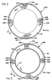
- FIG. 2 is a partial cross sectional view of the first planetary gearset 21A of the present invention taken along line II-II of FIG. 1.
- the first and second planetary gearsets 21A and 21B are disposed to rotate the control ring 14 in a direction to further activate the ball ramp mechanism 5.
- the first planetary gearset 21A (which has no sun gear) is comprised of a plurality of first planet gears 42A, 42B, 42C and 42D supported on respective first one-way clutches 44A, 44B, 44C and 44D each of which are nonrotatably supported on respective carrier pins 48A, 48B, 48C and 48D.
- first and second planetary gearsets 21A and 21B any number of planet gears and associated support pins could be utilized.
- the first planet gears 42A, 42B, 42C and 42D then mesh with the first annulus 40A which is attached to or formed from the first block 49A which rotates with the flywheel 4.
- the first and second planetary gears 42A, 42B, 42C, 42D, 43A, 43B, 43C and 43D are held in axial position by the carrier ring 39.
- the second planetary gearset 21B is comprised of a sun gear 54 driven by the transmission input shaft 8 meshing with a plurality of second planet gears 42A, 42B, 42C and 42D supported on respective second one-way clutches 45A, 45B, 45C and 45D each of which are nonrotatably supported on respective carrier pins 48A, 48B, 48C and 48D.
- the second planet gears 43A, 43B, 43C and 43D then mesh with second annulus 40B attached to or formed with second block 49B.
- the coil pole 32 is rotatably connected on the transmission input shaft 8 along with the sun gear 54.
- the first planet gears 42A, 42B, 42C, 42D and the second planet gears 43A, 43B, 43C, 43D are circumferentially spaced from one another by carrier ring 39 mounted on individual one-way clutches on extending carrier pins 48A, 48B, 48C, 48D.
- the first and second one-way clutches 44A, 44B, 44C, 44D, 45A, 45B, 45C, 45D acting in concert with the other elements of the first and second planetary gearsets 21A and 21B prevent the control ring 14 from rotating relative to the actuation ring 12 in a direction that would deactivate the ball ramp mechanism 5 as long as the coil 30 is energized by preventing rotation of the clutch ring 35 relative to the actuation ring 12 in that direction.
- the first and second planetary gearsets 21A and 21B operating in conjunction with the first and second one-way clutches 44A, 44B, 44C, 44D, 45A, 45B, 45C, 45D provide for relative rotation of the control ring 14 and the actuation ring 12 only in a direction which results in further activation of the ball ramp mechanism 5 and increased clamping force on the clutch discs 10 and 11 irregardless of the operational mode of the vehicle and torque flow through the driveline.
- FIG. 2 is a partial cross sectional view of the clutch assembly 2 of FIG. 1 taken along line II-II showing the relative rotation of the first planetary gearset 21A when the vehicle is in a drive mode.
- Arrow A 1 represents the direction of relative rotation of the first annulus 40A
- arrow P 1 represents the direction of relative rotation of the first planetary gears 42A, 42B, 42C, 42D
- arrow C represents the direction of relative rotation of the carrier ring 39.
- the annulus 40A is nonrotatably connected to the engine flywheel 4 and the first planet gears 42A, 42B, 42C and 42D are rotatably supported on their respective carrier pins 48A, 48B, 48C and 48D through first one-way clutches 44A, 44B, 44C and 44D where the carrier pins 48A, 48B, 48C and 48D are attached to the carrier ring 39.
- first annulus 40A is rotatably driven by the engine flywheel 4.
- the first planet gears 42A, 42B, 42C and 42D are rotating counterclockwise on respective first one-way clutches 44A, 44B, 44C and 44D but are prevented from rotating in a clockwise direction.
- the elements are rotating or prevented from rotating by one-way clutches as follows:
- the first annulus 40A is rotating with the engine flywheel 4 in a counterclockwise direction;
- the first planet gears 42A, 42B, 42C and 42D are rotating on their respective first one-way clutches 44A, 44B, 44C and 44D in a counterclockwise direction where the carrier pins 48A, 48B, 48C and 48D are stationary.
- FIG. 3 is a partial cross sectional view of the clutch assembly of FIG. 1 taken along line III-III showing the relative rotation of the second planetary gearset 21B when the vehicle is in the drive mode.
- Arrow S represents the direction of relative rotation of the sun gear 54
- arrow A 2 represents the direction of relative rotation of the second annulus 40B
- arrow P 2 represents the direction of relative rotation of the second planetary gears 43A, 43B, 43C, 43D
- arrow C represents the direction of relative rotation of the carrier ring 39.
- the second annulus 40B is nonrotatably connected to the clutch ring 35 which has a friction surface which frictionally couples the clutch ring 35 to the control ring 14 through the clutch extension member 29 when the coil 30 is energized.
- the second planet gears 43A, 43B, 43C and 43D are rotatably supported by respective carrier pins 48A, 48B, 48C and 48D are attached to the carrier ring 39.
- the second annulus 40B is nonrotatably connected to the clutch ring 35 which is frictionally coupled to the control ring 14 through the clutch extension member 29 when the coil 30 is energized.
- the second planetary gearset 21B has a sun gear 54 (unlike the first planetary gearset 21A) which is nonrotatably connected to the transmission input shaft 8.
- the second planet gears 43A, 43B, 43C and 43D are nonrotatably supported on respective carrier pins 48A, 48B, 48C and 48D on respective second one-way clutches 45A, 45B, 45C, 45D thereby preventing rotation of the second planet gears 43A, 43B, 43C, 43D in a clockwise direction.
- the sun gear 54 is shown rotating in a counterclockwise direction driven by the engine and since the second planet gears 43A, 43B, 43C and 43D are locked, the second annulus 40B rotates with the sun gear 54.
- any slippage of the friction discs 10A, 10B results in a further activation of the ball ramp mechanism 5 so as to increase the clamping load on the friction discs 10A and 10B even though the torque flow through the vehicle driveline has been reversed in FIG. 3.
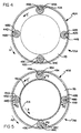
- FIG. 4 is a partial cross sectional view of the clutch assembly of FIG. 1 taken along the first planetary gearset 21A when the vehicle is in a coast mode where the driveline torque flow is reversal from that of the drive mode.
- Shown is the first annulus 40A rotating in a counterclockwise direction with the engine flywheel 4.
- the first planet gears 42A, 42B, 42C and 42D are locked from rotating in a counterclockwise direction by respective first one-way clutches 44A, 44B, 44C and 44D and thus, the carrier pins 48A, 48B, 48C and 48D along with the carrier ring 39 are rotated with the engine flywheel 4.
- Any driveline clutch slip results in relative rotation between the control ring 14 and activation ring 12 which further energizes the ball ramp mechanism 5 and increases the clamping force on the driveline clutch.
- the first planetary gearset 21A does not have a sun gear, it can be more accurately described as a partial planetary gearset.
- the first planetary gearset 21A functions as a one-way clutch operating between the flywheel 4 and carrier ring 39.
- the first planetary gearset 21A will be referred to as a planetary even though a sun gear is not utilized and it functions as a one-way clutch and not a traditional planetary gearset.
- FIG. 5 is a partial cross sectional view of the driveline clutch assembly 2 of FIG. 1 taken along line III-III showing the relative rotation of the second planetary gearset 21B when the vehicle is in the coast mode.
- the carrier ring 39 and the attached carrier pins 48A, 48B, 48C and 48D are rotating with the engine flywheel 4 since the second one-way clutches 45A, 45B, 45C and 45D are locked and preventing the second planetary gears 43A, 43B, 43C and 43D from rotating in a counterclockwise direction thereby reversing the input torque and causing the ball ramp mechanism 5 to be further energized when slippage occurs between the flywheel 4 and the friction disc 10A and 10B identical to that produced as the result shown in FIG. 3.
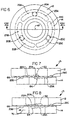
- FIGS. 6, 7 and 8 a cross-sectional view of the ball ramp mechanism 5 is shown in FIG. 6 and views taken along line VII-VII of the actuation ring 12 and the control ring 14 separated by a spherical element 20A are shown in FIGS. 7 and 8.
- Three spherical rolling elements 20A, 20B and 20C are spaced approximately 120° apart rolling in three ramps 22A, 22B and 22C having a variable axial depth respectively as the control ring 14 is rotated relative to the actuation ring 12.
- any number of spherical rolling elements 20A, 20B and 20C and respective ramps 22A, 22B, 22C, 23A, 23B and 23C could be utilized depending on the desired rotation and axial motion of the ball ramp mechanism 5. It is mandatory to employ at least three spherical rolling elements 20A, 20B and 20C traveling on a like number of identical equally spaced opposed ramps 22A, 22B, 22C, 23A, 23B and 23C formed respectively in both the control ring 14 and the actuation ring 12 to provide axial and radial stability to the control ring 14 and the actuation ring 12.
- any type of rolling elements could be utilized such as a ball or a cylindrical roller.
- the actuation ring 12 is shown which rotates with the flywheel 4, the pressure plate housing 16 and the first and second blocks 49A, 49B turning about axis of rotation 47 coincident with the axis of rotation of the transmission input shaft 8.
- Three semi-circular, circumferential ramps 23A, 23B and 23C are shown formed in the face of the actuation ring 12 with corresponding identical opposed ramps 22A, 22B and 22C formed in the face of the control ring 14.
- the control ring 14 and the actuation ring 12 are made of a high strength steel and the unidirectional tapered ramps 22A, 22B, 22C, 23A, 23B and 23C carburized and hardened to R c 55-60.
- the ramps 22A, 22B, 22C, 23A, 23B and 23C are tapered in depth as more clearly shown in FIG. 7 by references to ramps 22A and 23A and circumferentially extend for approximately 120° (actually less than 120° to allow for a separation section between the ramps).
- the separation 66 between the control ring 14 and the actuation ring 12 is determined by the rotational orientation between the two corresponding opposed ramps such as 22A and 23A where the spherical rolling element 20A rolls on both ramps 22A and 23A as the control ring 14 is rotated relative to the actuation ring 12 on the same axis of rotation.
- rolling element 20B rolls on both ramps 22B and 23B and rolling element 20C rolls on both ramps 22C and 23C.
- the relative rotation forces the two rings 14, 12 axially apart or allows them to come closer together as determined by the position of the rolling elements 20A, 20B and 20C or their respective ramp pairs 22A, 23A and 22B, 23B and 22C, 23C thereby providing an axial movement for clamping and releasing the clutch disc 10 between the actuation ring 12 and the flywheel 4.
- FIG. 7 illustrates the rotational orientation of the control ring 14 and the actuation ring 12 when the carrier ring 48 is at a minimum when the ramps 22A and 23A are at one extreme in alignment and the spherical element 20A is in the deepest section of the ramps 22A and 23A.
- the control ring 14 is rotated relative to the actuation ring 12 by application of a rotational torque input through the clutch coupling 24 and the ramps 22A and 23A move relative to one another causing the spherical element 20A to roll on each of the ramp surfaces 22A and 23A moving to a different position on both ramps 22A and 23A thereby forcing the control ring 14 and the actuation ring 12 apart to a wider separation 66 as shown in FIG. 8.
- a similar separation force is generated by rolling element 20B rolling on ramp surfaces 22B and 23B and by rolling element 20C rolling on ramp surfaces 22C and 23C.
- the rotation of the control ring 14 is clearly illustrated by reference to FIGS. 7 and 8 by the relative shift in position of reference points 62 and 64 from directly opposed in FIG. 7 to an offset position in FIG. 8 caused by rotation of the control ring 14 in the direction of the arrow 70.
- This increase in axial displacement can be used for a variety of applications, and especially driveline clutches, since the force level relative to the torque applied to the control ring 14 is quite high, typically a ratio of 100:1.
- This can be used as illustrated in this application to load an actuation ring 12 against clutch discs 10 and 11 and flywheel 4 in a vehicle driveline. Additional illustrative details of operation of a ball ramp actuator can be found by reference to U.S. Patent No. 4,805,486.
- any relative rotation between the flywheel 4 and the transmission input shaft 8 results in relative rotation between the control ring 14 and the actuation ring 12 in a direction which causes the spherical elements 20A, 20B and 20C to further increase the separation 66 between the control ring 14 and the actuation ring 12 thereby generating additional clamping force by the actuation ring 12 so as to use the power of the flywheel to increase the lock-up force on the clutch disc 10.
- the vehicle driveline clutch actuator can be used to couple a rotating input shaft to an output shaft where the input shaft would be analogous to the flywheel 4 and the output shaft would be analogous to the transmission input shaft 8 as shown in FIG. 1.
- the present invention would prevent the ball ramp mechanism 5 from retracting and disengaging the clutch discs 10 and 11 so long as the coil 30 was energized thereby providing a friction coupling between the input shaft (flywheel) and the output shaft (transmission input shaft) irregardless of the direction of the torque transfer.
Landscapes
- Engineering & Computer Science (AREA)
- General Engineering & Computer Science (AREA)
- Physics & Mathematics (AREA)
- Electromagnetism (AREA)
- Mechanical Engineering (AREA)
- Mechanical Operated Clutches (AREA)
- Hydraulic Clutches, Magnetic Clutches, Fluid Clutches, And Fluid Joints (AREA)
- Arrangement Of Transmissions (AREA)
Description
- The present invention relates to a vehicle driveline clutch and, more particularly, to a driveline clutch where a friction disc is clamped to an engine flywheel using a ball ramp actuator wherein an electromagnetically actuated cone clutch is used to control the torque transferred to the ball ramp actuator.
- Driveline master clutches commonly use a plurality of springs to clamp a friction disc to an engine flywheel. The springs are disposed within a pressure plate assembly which is bolted to the flywheel. A mechanical linkage that controls the pressure plate spring mechanism is displaced by the operator to control the lock-up and release of the driveline clutch.
- Efforts to automate the operation of the driveline clutch using electronics are currently underway. It is known to use an electromechanical or hydraulic actuator connected to the mechanical linkage to, in essence, replace the operator for more accurate clutch operation during transmission shifting. Using such an actuator, the mechanical linkage is moved in response to an electrical control signal generated by a central microprocessor used to process a variety of vehicle sensor inputs based on operating conditions to determine when and in what manner the driveline clutch should be activated or deactivated.
- The use of a ball ramp actuator to load a clutch pack in a vehicle driveline differential is known. U.S. Patent Nos. 4,805,486 and 5,092,825, disclose limited slip differentials where a clutch pack is loaded in response to the activation of a ball ramp actuator initiated by rotation of a servo motor or a solenoid driven brake shoe on an activation ring. The advantage of the ball ramp mechanism over other actuators is that it converts rotary motion into axial motion with very high force amplification, often 100:1 or greater. A ball ramp actuator has also been utilized in a vehicle transmission to engage and disengage gearsets by loading a gear clutch pack in response to a signal as disclosed in U.S. Patent No. 5,078,249.
- In both of these vehicle applications, one side of the ball ramp actuator, commonly called a control ring, reacts against case ground through the force induced by an electromagnetic field generated by a coil or is rotated by an electric motor relative to case ground. To generate greater clamping forces, the electrical current supplied to the coil or motor is increased thereby increasing the reaction of the control ring to case ground which rotates the control ring relative to an actuation ring thereby causing rolling elements to traverse ramps in the control and actuation ring which increase the axial movement and clamping force on the clutch pack.
- It is also known to use a ball ramp actuator to load a vehicle driveline clutch as disclosed in U.S. Patent Nos. 1,974,390; 2,861,225; 3,000,479; 5,441,137; 5,469,948; 5,485,904 and 5,505,285. One problem with the use of a ball ramp actuator to supply the vehicle driveline clutch clamping force is that the mechanics of prior art unidirectional ball ramp mechanisms result in a loss of clamping force when the vehicle is in a coast mode. Once the engine power is reduced and the driveline is actually overrunning the engine (coast mode), the prior art ball ramp actuator with single ramp unidirectional actuation will disengage the clutch thereby eliminating engine braking of the vehicle.
- A ball ramp actuated clutch using a unidirectional ball ramp having only a single ramp angle, will cause the clutch to disengage when the engine is not supplying rotational energy into the transmission such as when the vehicle is coasting. When coasting, the flywheel is no longer supplying rotational energy to either the transmission or to the ball ramp actuator. In this circumstance, the relative rotation of the actuation ring and control ring has been reversed such that the ball ramp axial displacement is collapsed thereby allowing the pressure plate to pull away from the clutch disc. The result is that the engine is disengaged from the transmission and any engine braking effect is eliminated.
- A bidirectional ball ramp actuated clutch is disclosed in U.S. Patent Nos. 2,937,729 and 5,505,285. Using this more expensive and complicated technology, the ball ramp actuator incorporates bidirectional ramps which provide activation when there is relative rotation between the control ring and the actuation ring in either direction. However, the ball ramp must transition through the nonactivated state which will result in temporary undesirable clutch slippage and, in addition, the components are more expensive to fabricate than a unidirectional unit. Also, a bidirectional ball ramp will have reduced rotational travel between the control ring and the actuation ring in a given package size as compared to a unidirectional ball ramp mechanism. Thus, a unidirectional ball ramp mechanism is preferred if it can be made to activate in both vehicle drive and coast operating modes.
- The ball ramp actuator comprises a plurality of rolling elements, a control ring and an opposed actuation ring where the actuation ring and the control ring define at least three opposed single ramp surfaces formed as circumferential semi-circular grooves, each pair of opposed grooves containing one rolling element. A thrust bearing is interposed between the control ring and a housing member, rotating with and connected to the input member such as a flywheel. An electromagnetic coil is disposed adjacent to one element of a control clutch so as to induce a magnetic field that loads the control clutch which in turn applies a force on the control ring of the ball ramp actuator. The control clutch can be similar to those commonly used for vehicle air conditioning compressors, or a cone type control clutch to increase the transmitted actuation force. In an electromagnetic type of clutch, the air gap present in the clutch is traversed by an armature when the coil is energized and the forces on the armature increase in an exponential manner as the armature is drawn toward the stator/coil. The dramatic force increase as the armature is moved results in difficulty in controlling the operation of the ball ramp mechanism and hence the driveline clutch which is loaded by the ball ramp mechanism. Thus, it would be desirable to eliminate or minimize the effect of the air gap in the control clutch for smoother engagement of the driveline clutch especially during vehicle start up.
- The present invention is described in claims 1 and 6 and relates to a flywheel driven by a prime mover and a transmission input shaft coupled through a ball ramp actuated clutch. The ball ramp mechanism has a plurality of unidirectional variable depth grooves (ramps) and an actuation ring having single direction variable depth grooves at least partially opposed and substantially similar in geometry to those of the control ring. Examples of ball ramp actuator clutch systems are shown in U.S. Patent Nos. 1,974,390; 2,861,225; 2,937,729; 3,000,479; 5,485,904 and 5,505,285 forming a basis for the preamble of claim 1 and 6. The actuation ring is prevented from counter rotating upon clutch lock-up in the vehicle coast mode through the use of one-way clutches. Two planetary gearsets (one of which is a partial planetary and functions as a large diameter one-way clutch) are used to allow the ball ramp actuator to increase the clamping force on the clutch friction disc both in drive and coast modes with no reduction in clamping force when transistioning from one mode to the other mode.
- A cone clutch is used to transfer rotation from the transmission input shaft to the control ring of the ball ramp mechanism. The cone clutch is engaged upon axial movement of the armature (control clutch plate) toward a coil pole in response to an electrical current in a coil. According to the present invention, a biasing spring is used to apply a minimum continuous force on the armature toward the coil pole. This biasing force moves the armature toward the coil pole thereby minimizing the air gap that must be traversed by the armature prior to significant engagement of the cone clutch.
- The electromagnetic coil is used to activate the control clutch which frictionally couples the control ring through one of the planetary gearsets to the transmission input shaft. When energized by the coil, the ball ramp mechanism provides a clamping force on the driveline clutch friction disc where the amplitude of the clamping force immediately increases whenever there exists a rotational speed differential between the flywheel and the transmission input shaft. The amplitude of the clamping force is held at a given level or increased as long as the coil is energized by action of one-way clutches acting on individual planet gears in the two planetary gearsets so that when the vehicle enters a coasting mode (where the engine is braking as opposed to driving the vehicle) the ball ramp actuator remains fully activated. Clutch slippage in the drive mode will cause the ball ramp mechanism to increase the clamping force on the clutch disc. Also, in the coasting mode, if for some reason there is clutch slippage, the planetary gearsets provide for additional relative rotation between the control ring and the actuation ring in the proper direction to increase the clamping force on the clutch friction discs.
- One provision of the present invention is to minimize the air gap in the control clutch of a ball ramp mechanism.
- Another provision of the present invention is to minimize the air gap in the control clutch of a ball ramp mechanism using a biasing force on the armature of an electromagnetic actuator.
- Another provision of the present invention is to minimize the air gap in the control clutch of a ball ramp mechanism using a biasing spring acting between the actuator ring ad the armature of an electromagnetic actuator.
-
- FIG. 1 is a partial cross-sectional view of the ball ramp actuator of the present invention;
- FIG. 2 is a partial cross-sectional view of the first planetary gearset of the present invention taken along line II-II of FIG. 1 with the vehicle driveline in a drive mode;
- FIG. 3 is a partial cross-sectional view of the second planetary gearset of the present invention taken along line II-II of FIG. 1 with the vehicle driveline in a drive mode;
- FIG. 4 is a partial cross-sectional view of the first planetary gearset of the present invention taken along line III-III of FIG. 1 with the vehicle driveline in a coast mode;
- FIG. 5 is a partial cross-sectional view of the second planetary gearset of the present invention taken along line III-III of FIG. 1 with the vehicle driveline in a coast mode;
- FIG. 6 is an axial cross-sectional view of the ball ramp mechanism of the present invention taken along line VI-VI of FIG. 1;
- FIG. 7 is a cross-sectional view of the ball ramp mechanism of the present invention taken along line VII-VII of FIG. 6 with the ball ramp mechanism in a non-energized state; and
- FIG. 8 is a cross-sectional view of the ball ramp mechanism of the present invention taken along line VII-VII of FIG. 6 with the ball ramp mechanism in an energized state.
-
- For purposes of promoting the understanding of the principles of the invention, reference will now be made to the embodiment illustrated in the drawings and specific language will be used to describe the same.
- Certain terminology will be used in the following description for convenience in reference only and will not be limiting. For example, the terms "forward" and "rearward" will refer to directions forward and rearward of the clutch assembly as normally mounted in a vehicle. The terms "rightward" and "leftward" will refer to directions in the drawings in connection with which the terminology is used. The terms "inwardly" and "outwardly" will refer to directions toward and away from respectively, the geometric center of the apparatus. The terms "upward" and "downward" will refer to directions as taken in the drawings in connection with which the terminology is used. All foregoing terms mentioned above include the normal derivatives and equivalents thereof.
- Referring now to the drawings, which are not intended to limit the present invention, FIG. 1 is an axial cross-sectional view of a master driveline clutch assembly 2 of the type in which the present invention may be utilized. The main driveline clutch assembly 2 includes a flywheel 4 having a friction surface 4A rotatably driven by a prime mover (not shown) such as an internal combustion engine by its output crankshaft (not shown) which is coupled to a transmission (not shown) by a driveline clutch assembly 2 actuated by a ball ramp mechanism 5. A clutch bellhousing 6 surrounds the driveline clutch assembly 2 and supports the transmission including the transmission input shaft 8 which extends to nonrotatably engage a first clutch disc 10 having friction disc 10A and friction disc 10B through splines 10C at the left end of the transmission input shaft 8 of where the transmission input shaft 8 then extends rightward to drive the transmission gearing. Likewise, a second clutch disc 11 having friction disc 11A and friction disc 11B engages the transmission input shaft 8 through splines 11C. The first clutch disc 10 is clamped between the flywheel 4 and an intermediate pressure plate 13 while the second clutch disc 11 is clamped between the
intermediate pressure plate 13A and aprimary pressure plate 13B. Anactuation ring 12, acts on the Bellville washer 18 to apply an axial force on theprimary pressure plate 13B against the second clutch disc 11 and theintermediate pressure plate 13A against the first clutch disc 10 against the flywheel 4 at the flywheel friction surface 4A thereby transferring the rotational power from the prime mover to the transmission through the transmission input shaft 8 and eventually to the rest of the vehicle driveline. - In prior art systems, the clutch pressure plate is forced toward the flywheel using a plurality of loading springs. When the operator wishes to disengage the clutch disc, a mechanical release mechanism is activated by the operator's foot and leg overcoming the force of the springs thereby allowing the clutch disc to slip relative to the flywheel. It should be understood, however, that neither the activation springs nor the mechanical'release mechanism are features of the present invention. According to the present invention, a ball ramp mechanism 5 incorporating an
activation ring 12 and acontrol ring 14 separated by at least threerolling elements 20A riding in variable depth ramps orgrooves actuation ring 12 toward the flywheel 4 which is controlled by the clutch control unit 15 electronically taking the place of an operator during transmission shifting sequences. - The clutch bellhousing 6 partially encloses the driveline clutch assembly 2 including the ball ramp mechanism 5 of the present invention. Ball ramp actuators that react the
control ring 14 to ground are well known in the art and have been used to load transmission gear clutches as disclosed in U.S. Patent No. 5,078,249, and differential clutch packs as disclosed in U.S. Patent No. 5,092,825 where a ball ramp control ring is reacted against case ground by a coil or motor with gearing. In essence, relative rotational motion between thecontrol ring 14 and theactuation ring 12 causes one or morerolling elements opposed ramps control ring 14 and ramps 23A, 23B and 23C formed in theactuation ring 12 respectively.Ramps control ring 14 relative to theactuation ring 12 causes theactuation ring 12 to move axially toward the flywheel 4 thereby clamping the first and second clutch discs 10 and 11 between theactuation ring 12 and the flywheel 4. Centering spring 26 tends to restrain rotation of theactuation ring 12 relative to thecontrol ring 14 so that the ball ramp mechanism 5 is not energized by rotational inertial forces which could cause inadvertent engagement of the driveline clutch assembly 2. Theactuation ring 12 is nonrotatably connected to thepressure plate housing 16 but can move axially with respect thereto. FIGS. 6-8 illustrate this geometry with more detail and precision, reference to which is made subsequently. - Thrust bearing 56, which can be any type of suitable bearing, reacts against the second block 49B which is attached to the
first block 49A and is used to contain the axial forces generated by the ballramp rolling elements ramps control ring 14 and theactuation ring 12 respectively (see FIG. 2). In general a planetary gearset consists of an annulus, sun gear and at least three planetary gears. Thefirst annulus 40A of the secondplanetary gearset 21B is attached to thefirst block 49A which is attached to the flywheel 4 through thepressure plate housing 16. Thesecond annulus 40B is supported by but rotates independently of the second block 49B but is rotationally connected to theclutch ring 35. Thesun gear 54 only engages the secondplanetary gearset 21B and the firstplanetary gearset 21A does not use a sun gear and functions as a large diameter one-way clutch. The first and second planet gears 42A and 43A are supported onsupport pin 48A through respective one-way clutches carrier ring 39. The other planet gears 42B, 43B, 42C, 43C, 42D and 43D are supported on respective support pins 48B, 48C and 48D through respective one-way clutches planetary gearset 21A functions as a one-way clutch. The elements of the present invention generally encircle the transmission input shaft 8 and rotate about the axis ofrotation 47. - The clutch control unit 15 supplies a controlled electrical current through leads 17 to a
coil 30 which activates the clutch coupling 24 which consists of a cone clutch 28, one side of which is theclutch ring 35 which is nonrotatably connected to the annulus 40 of the planetary gearset 21 and the other side is nonrotatably connected to thecontrol ring 14 through the clutch extension 29.Mating channels 37 extend from thecontrol ring 14 and rotationally engage drive flanges 38 extending from the clutch extension 29 which is attached to the controlclutch plate 19 which form the clutch coupling 24. In this manner, the cone clutch 28 frictionally couples thecontrol ring 14 to the clutch ring 35 (which is nonrotatably connected to the annulus 40) when thecoil 30 is electrically energized by the clutch control unit 15 through leads 17 which electromagnetically attracts the controlclutch plate 19 and loads the cone clutch 28. It is desirable to bond friction material to either the control clutch extension member 29 and/or theclutch ring 35 at the cone clutch 28 to provide for the desired torque transfer between these elements when the coil is energized. The clutch extension member 29 uses the drive flanges 38 extending therefrom to rotationally drive one side of the cone clutch 28 without radial and axial alignment problems because of the manner in which the drive flanges 38 engage thedrive channels 37. Without this type of clutch coupling 24, the cone clutch 28 would tend to bind due to the production tolerances and wear of the components that make up the clutch coupling 24. - The
control ring 14 contains theramps clutch ring 35 when thecoil 30 is energized by action of the clutch coupling 24. The controlclutch member 19 is drawn against thecoil pole 32 when thecoil 30 is energized by the clutch control unit 15 through connectors 17. The annularelectrical coil 30 encircles the transmission input shaft 8 and is supported by thecoil support 31 attached to the clutch bellhousing 6. Theelectrical coil 30 is positioned in close proximity to thecoil pole 32 where thecoil pole 32 is nonrotatably supported on the transmission input shaft 8 on thesplined sleeve 33. Thus, thesplined sleeve 33 and thecoil pole 32 and thesun gear 54 all rotate with the transmission input shaft 8. Theelectrical coil 30 is positioned to be partially enclosed by thecoil pole 32 and is separated from it by a small air gap. Thecoil 30 is mounted to the clutch bellhousing 6 and therefore held stationary while thecoil pole 32 rotates according to the rotation of the input shaft 8. Thecoil 30 generates an electromagnetic flux illustrated byarrows 36 in FIG. 1 which travel through thecoil pole 32 into the controlclutch member 19 and back through thecoil pole 32 into thecoil 30. This electromagnetic flux creates a force tending to draw theclutch member 19 into thecoil pole 32 thereby creating a frictional force through contact of the clutch extension member 29 onclutch ring 35 and a torque into theplanetary gearsets planetary gearsets control ring 14 in a locking direction when the vehicle is in either a coast or drive mode. - When the clutch disc 10 or 11 are unclamped or start to slip due to excessive torque supplied by the prime mover (engine) through the flywheel 4, there is relative rotation between the
control ring 14 and theactuation ring 12 thereby forcing therings actuation ring 12 on the clutch discs 10 and 11 at the friction pads 10A, 10B, 11A and 11B between themain pressure plate 13A and theintermediate pressure plate 13A and the flywheel 4. This occurs through a small range of rotational motion of thecontrol ring 14 relative to theactuation ring 12 and provides an automatic, virtually instant, clamping force adjustment should any relative rotation occur between the flywheel 4 and the transmission input shaft 8 by action of the ball ramp mechanism 5. - According to the present invention, once the clutch assembly 2 is locked-up, the
coil pole 32 rotates at the same speed as the flywheel 4 and minimal parasitic electrical power is required to be delivered to thecoil 30 to maintain lock-up of clutch assembly 2. Using the teaching of the prior art, thecontrol ring 14 can be reacted against a ground surface, such as the clutch bellhousing 6, although continuous slipping would occur between thecontrol ring 14 resulting in high parasitic energy losses and no automatic activation of the ball ramp mechanism 5 upon clutch slip. As illustrated in the present application, by attaching thecontrol ring 14 to the transmission input shaft 8 through the first and secondplanetary gearsets way clutches actuation ring 12, and thecontrol ring 14 through the frictionally locked clutch coupling 24 and the first and secondplanetary gearsets control ring 14 side and through thepressure plate housing 16 to theactuation ring 12 resulting in further activation of the ball ramp mechanism 5. Theactuation ring 12 is rotationally coupled to the clutchpressure plate housing 16 which is in turn connected to the flywheel 4 all rotating together. - The bias spring 26 pre-loads the control
clutch plate 19 toward thecoil pole 32 to minimize air gap effects and functions to control the axial position of thecontrol ring 14 relative to theactuation ring 12 when theelectrical coil 30 is not energized such that a linear force is required to progressively energized the ball ramp mechanism 5. Without the biasing spring 26 theclutch plate 19 would be free to separate some distance from thecoil plate 32 when thecoil 30 is not energized and the clutch assembly 2 was in a nonengaged mode. Then, when thecoil 30 was energized, a relatively high current would be required to draw theclutch plate 19 toward thecoil plate 33 over the separation distance. As theclutch plate 19 moved toward thecoil plate 33 the attraction force would rapidly increase without a change in the current in thecoil 30 resulting in a sudden energization of the ball ramp mechanism 5. Without a sophisticated electrical control system the force transferred into the cone clutch 28 would exceed the desired level for a smooth activation of the driveline clutch assembly 2. The biasing spring 26 is shown as a compression spring disposed between thecontrol ring 14 and theactuation ring 12 but could be any type of device that would apply a biasing force on theclutch member 19 to minimize the air gap. Thus, the biasing spring 26 applies a force on theclutch plate 19 such that theclutch plate 19 maintains a minimum separation from thecoil plate 32 at all times. This provides for a smooth activation of the ball ramp mechanism 5. It is contemplated that any type of spring means could be utilized to create a biasing force between theclutch member 19 and thecoil plate 32. The biasing spring 26 is trapped betweenhousing 55 andretention ring 57 which are free to axially move relative to one another. Thehousing 55 is attached to theactuation ring 12 where theretention ring 57 contacts theclutch plate 19. The bias spring contacts thehousing 55 and theretention ring 57 forcing them apart. The resulting force tends to force theclutch plate 19 towards thecoil pole 32 and the clutch extension 29 towards theclutch ring 35. This preloads the clutch coupling 24 so that when thecoil 30 is energized, the clutch coupling 24 smoothly engages and activates the ball ramp mechanism 5 in a controlled manner. - A plurality of pressure plate springs 50 act to pull the ball ramp mechanism 5 including the
actuation ring 12 away from the clutch friction discs 10 and 11 and the flywheel 4 by acting as spring elements between thepressure plate housing 16 and theactuation ring 12 thereby biasing theactuation ring 12 away from the flywheel 4. Thepressure plate housing 16 is attached to the flywheel 4 such that theactuation ring 12 rotates with the flywheel 4 but can move axially relative to the flywheel 4 as controlled by action of the ball ramp mechanism 5 acting to compress the pressure plate springs 50. - Axial forces generated by the ball ramp mechanism 5 are transmitted by the thrust bearing 56 into the second blocks 49B which is attached to the flywheel 4 through the
pressure plate housing 16. In the opposite direction, the force generated by the ball ramp mechanism 5 is transmitted to the clutch discs 10 and 11 and the flywheel 4. It should be noted that any number of clutch discs could be utilized including only one clutch disc without theintermediate pressure plate 13A. - Reference is now made to both FIGS. 1 and 2 where FIG. 2 is a partial cross sectional view of the first
planetary gearset 21A of the present invention taken along line II-II of FIG. 1. The first and secondplanetary gearsets control ring 14 in a direction to further activate the ball ramp mechanism 5. The firstplanetary gearset 21A (which has no sun gear) is comprised of a plurality of first planet gears 42A, 42B, 42C and 42D supported on respective first one-way clutches planetary gearsets first annulus 40A which is attached to or formed from thefirst block 49A which rotates with the flywheel 4. The first and secondplanetary gears carrier ring 39. The secondplanetary gearset 21B is comprised of asun gear 54 driven by the transmission input shaft 8 meshing with a plurality of second planet gears 42A, 42B, 42C and 42D supported on respective second one-way clutches second annulus 40B attached to or formed with second block 49B. Thecoil pole 32 is rotatably connected on the transmission input shaft 8 along with thesun gear 54. - The first planet gears 42A, 42B, 42C, 42D and the second planet gears 43A, 43B, 43C, 43D are circumferentially spaced from one another by
carrier ring 39 mounted on individual one-way clutches on extending carrier pins 48A, 48B, 48C, 48D. The first and second one-way clutches planetary gearsets control ring 14 from rotating relative to theactuation ring 12 in a direction that would deactivate the ball ramp mechanism 5 as long as thecoil 30 is energized by preventing rotation of theclutch ring 35 relative to theactuation ring 12 in that direction. Upon energization of thecoil 30, the first and secondplanetary gearsets way clutches control ring 14 and theactuation ring 12 only in a direction which results in further activation of the ball ramp mechanism 5 and increased clamping force on the clutch discs 10 and 11 irregardless of the operational mode of the vehicle and torque flow through the driveline. - FIG. 2 is a partial cross sectional view of the clutch assembly 2 of FIG. 1 taken along line II-II showing the relative rotation of the first
planetary gearset 21A when the vehicle is in a drive mode. Arrow A1 represents the direction of relative rotation of thefirst annulus 40A, arrow P1 represents the direction of relative rotation of the firstplanetary gears carrier ring 39. Theannulus 40A is nonrotatably connected to the engine flywheel 4 and the first planet gears 42A, 42B, 42C and 42D are rotatably supported on their respective carrier pins 48A, 48B, 48C and 48D through first one-way clutches carrier ring 39. Assuming the engine is rotating in a counterclockwise direction, thefirst annulus 40A is rotatably driven by the engine flywheel 4. The first planet gears 42A, 42B, 42C and 42D are rotating counterclockwise on respective first one-way clutches first annulus 40A is rotating with the engine flywheel 4 in a counterclockwise direction; the first planet gears 42A, 42B, 42C and 42D are rotating on their respective first one-way clutches - FIG. 3 is a partial cross sectional view of the clutch assembly of FIG. 1 taken along line III-III showing the relative rotation of the second
planetary gearset 21B when the vehicle is in the drive mode. Arrow S represents the direction of relative rotation of thesun gear 54, arrow A2 represents the direction of relative rotation of thesecond annulus 40B, arrow P2 represents the direction of relative rotation of the secondplanetary gears carrier ring 39. Thesecond annulus 40B is nonrotatably connected to theclutch ring 35 which has a friction surface which frictionally couples theclutch ring 35 to thecontrol ring 14 through the clutch extension member 29 when thecoil 30 is energized. The second planet gears 43A, 43B, 43C and 43D are rotatably supported by respective carrier pins 48A, 48B, 48C and 48D are attached to thecarrier ring 39. Thesecond annulus 40B is nonrotatably connected to theclutch ring 35 which is frictionally coupled to thecontrol ring 14 through the clutch extension member 29 when thecoil 30 is energized. The secondplanetary gearset 21B has a sun gear 54 (unlike the firstplanetary gearset 21A) which is nonrotatably connected to the transmission input shaft 8. In the drive mode, the second planet gears 43A, 43B, 43C and 43D are nonrotatably supported on respective carrier pins 48A, 48B, 48C and 48D on respective second one-way clutches sun gear 54 is shown rotating in a counterclockwise direction driven by the engine and since the second planet gears 43A, 43B, 43C and 43D are locked, thesecond annulus 40B rotates with thesun gear 54. Thus, any slippage of the friction discs 10A, 10B results in a further activation of the ball ramp mechanism 5 so as to increase the clamping load on the friction discs 10A and 10B even though the torque flow through the vehicle driveline has been reversed in FIG. 3. - FIG. 4 is a partial cross sectional view of the clutch assembly of FIG. 1 taken along the first
planetary gearset 21A when the vehicle is in a coast mode where the driveline torque flow is reversal from that of the drive mode. Shown is thefirst annulus 40A rotating in a counterclockwise direction with the engine flywheel 4. The first planet gears 42A, 42B, 42C and 42D are locked from rotating in a counterclockwise direction by respective first one-way clutches carrier ring 39 are rotated with the engine flywheel 4. Any driveline clutch slip results in relative rotation between thecontrol ring 14 andactivation ring 12 which further energizes the ball ramp mechanism 5 and increases the clamping force on the driveline clutch. - Since the first
planetary gearset 21A does not have a sun gear, it can be more accurately described as a partial planetary gearset. The firstplanetary gearset 21A functions as a one-way clutch operating between the flywheel 4 andcarrier ring 39. For purposes of this application, the firstplanetary gearset 21A will be referred to as a planetary even though a sun gear is not utilized and it functions as a one-way clutch and not a traditional planetary gearset. - FIG. 5 is a partial cross sectional view of the driveline clutch assembly 2 of FIG. 1 taken along line III-III showing the relative rotation of the second
planetary gearset 21B when the vehicle is in the coast mode. Thecarrier ring 39 and the attached carrier pins 48A, 48B, 48C and 48D are rotating with the engine flywheel 4 since the second one-way clutches planetary gears - Referring now to FIGS. 6, 7 and 8 to describe the operation of the ball ramp mechanism 5, a cross-sectional view of the ball ramp mechanism 5 is shown in FIG. 6 and views taken along line VII-VII of the
actuation ring 12 and thecontrol ring 14 separated by aspherical element 20A are shown in FIGS. 7 and 8. Threespherical rolling elements ramps control ring 14 is rotated relative to theactuation ring 12. Any number of sphericalrolling elements respective ramps spherical rolling elements opposed ramps control ring 14 and theactuation ring 12 to provide axial and radial stability to thecontrol ring 14 and theactuation ring 12. As mentioned previously, any type of rolling elements could be utilized such as a ball or a cylindrical roller. Theactuation ring 12 is shown which rotates with the flywheel 4, thepressure plate housing 16 and the first andsecond blocks 49A, 49B turning about axis ofrotation 47 coincident with the axis of rotation of the transmission input shaft 8. - Three semi-circular,
circumferential ramps actuation ring 12 with corresponding identicalopposed ramps control ring 14. Thecontrol ring 14 and theactuation ring 12 are made of a high strength steel and the unidirectionaltapered ramps ramps ramps separation 66 between thecontrol ring 14 and theactuation ring 12 is determined by the rotational orientation between the two corresponding opposed ramps such as 22A and 23A where thespherical rolling element 20A rolls on bothramps control ring 14 is rotated relative to theactuation ring 12 on the same axis of rotation. In a substantially identical manner, rollingelement 20B rolls on bothramps element 20C rolls on bothramps rings elements actuation ring 12 and the flywheel 4. - FIG. 7 illustrates the rotational orientation of the
control ring 14 and theactuation ring 12 when the carrier ring 48 is at a minimum when theramps spherical element 20A is in the deepest section of theramps coil 30, thecontrol ring 14 is rotated relative to theactuation ring 12 by application of a rotational torque input through the clutch coupling 24 and theramps spherical element 20A to roll on each of the ramp surfaces 22A and 23A moving to a different position on bothramps control ring 14 and theactuation ring 12 apart to awider separation 66 as shown in FIG. 8. A similar separation force is generated by rollingelement 20B rolling onramp surfaces element 20C rolling onramp surfaces control ring 14 is clearly illustrated by reference to FIGS. 7 and 8 by the relative shift in position ofreference points control ring 14 in the direction of thearrow 70. This increase in axial displacement can be used for a variety of applications, and especially driveline clutches, since the force level relative to the torque applied to thecontrol ring 14 is quite high, typically a ratio of 100:1. This can be used as illustrated in this application to load anactuation ring 12 against clutch discs 10 and 11 and flywheel 4 in a vehicle driveline. Additional illustrative details of operation of a ball ramp actuator can be found by reference to U.S. Patent No. 4,805,486. - If the flywheel 4 is rotating at the same speed as the transmission input shaft 8, even if the
coil 30 is energized, thecontrol ring 14 rotates at the same speed as theactuation ring 12 and no additional axial force is generated by the ball ramp mechanism 5 since there is no relative rotation between thecontrol ring 14 and theactuation ring 12. Assuming thecoil 30 remains energized thereby electromagnetically tying thecontrol ring 14 to the transmission input shaft 8 through the clutch coupling 24,coil pole 32 and the first and secondplanetary gearsets control ring 14 and theactuation ring 12 in a direction which causes thespherical elements separation 66 between thecontrol ring 14 and theactuation ring 12 thereby generating additional clamping force by theactuation ring 12 so as to use the power of the flywheel to increase the lock-up force on the clutch disc 10. - According to the present invention, the vehicle driveline clutch actuator can be used to couple a rotating input shaft to an output shaft where the input shaft would be analogous to the flywheel 4 and the output shaft would be analogous to the transmission input shaft 8 as shown in FIG. 1. The present invention would prevent the ball ramp mechanism 5 from retracting and disengaging the clutch discs 10 and 11 so long as the
coil 30 was energized thereby providing a friction coupling between the input shaft (flywheel) and the output shaft (transmission input shaft) irregardless of the direction of the torque transfer. - This invention has been described in great detail, sufficient to enable one skilled in the art to make and use the same. Various alterations and modifications of the invention will occur to those skilled in the art upon a reading and understanding of the foregoing specification, and it is intended to include all such alterations and modifications as part of the invention, insofar as they come within the scope of the appended claims.
Claims (15)
- A clutch assembly (2) for rotationally coupling two rotating elements comprising:an input element (4) driven by a prime mover and rotating about an axis of rotation (47);an output element (8) rotationally coupled to said input element (4) usinga ball ramp mechanism (5) for generating an axial movement, the mechanism comprising; an annular control ring (14) having an axis of rotation (47), said control ring (14) having a plurality of circumferential control ramps (23A, 23B, 23C) formed in a first face of said control ring (14), said control ramps (23A, 23B, 23C) varying in axial depth, an equivalent number of rolling elements (20A, 20B, 20C) one occupying each of said control ramps (23A, 23B, 23C), an actuation ring (12) having an axis of rotation (47) coaxial with said axis of rotation (47) of said control ring (14), said actuation ring (12) having a plurality of actuation ramps (22A, 22B, 22C) substantially identical in number, shape and radial position to said control ramps (23A, 23B, 23C) where said actuation ramps (22A, 22B, 22C) at least partially oppose said control ramps (23A, 23B, 23C) and where each of said rolling elements (20A, 20B, 20C) is contained between one of said actuation ramps (22A, 22B, 22C) and a respective control ramp (23A, 23B, 23C), said control ring (14) being axially and rotationally moveably disposed relative to said actuation ring (12);a coil (30) for creation of an electromagnetic field in a coil pole (32) upon introduction of an electrical current in said coil (30);a clutch coupling (24) having a clutch plate (19) positioned adjacent to said coil pole (32) disposed to apply a rotational torque to said control ring (14) to activate said ball ramp mechanism (5) upon creation of an electromagnetic field (36) by said coil (30) ; characterized in that the assembly comprises:biasing means (26) for creating a force on said clutch plate (19) tending to move said clutch plate (19) toward said coil pole (32).
- The clutch assembly of claim 1, wherein said biasing means (26) is an axially acting coil spring.
- The clutch assembly of claim 1, wherein said biasing means (26) creates a force between said clutch plate (19) and said actuation ring (12).
- The clutch assembly of claim 1, wherein said input element (4) is an engine flywheel and said output element (8) is a transmission input shaft.
- The clutch assembly of claim 1, wherein said control clutch (24) further comprises a cone clutch (28) loaded by said clutch plate (19).
- A ball ramp actuator for rotationally coupling two rotating elements comprising:characterized in that the assembly comprises :an input element (4) driven by a prime mover and rotating about an axis of rotation (47);an output element (8) having an axis of rotation (47) coaxial with said axis of rotation (47) of said input element (4) for rotating an output device;a ball ramp mechanism (5) for generating an axial movement comprising; an annular control ring (14) having an axis of rotation (47), said control ring (14) having a plurality of circumferential control ramps (23A, 23B, 23C) formed in a first face of said control ring (14), said control ramps (23A, 23B, 23C) varying in axial depth, an equivalent number of rolling elements (20A, 20B, 20C) one occupying each of said control ramps (23A, 23B, 23C), an actuation ring (12) having an axis of rotation (47) coaxial with said axis of rotation (47) of said control ring (14), said actuation ring (12) having a plurality of actuation ramps (22A, 22B, 22C) substantially identical in number, shape and radial position to said control ramps (23A, 23B, 23C) where said actuation ramps (22A, 22B, 22C) at least partially oppose said control ramps (23A, 23B, 23C) and where each of said rolling elements (20A, 20B, 20C) is contained between one of said actuation ramps (22A, 22B, 22C) and a respective control ramp (23A, 23B, 23C), said control ring (14) being axially and rotationally moveably disposed relative to said actuation ring (12);a control clutch (24) for frictionally coupling said control ring (14) to said output element (8);a clutch ring (35) frictionally rotationally coupled to said control ring (14);a coil (30) for inducing an electromagnetic field (36) in said clutch control member (19) to frictionally couple said clutch ring (35) to said control ring (14) ;a coil pole (32) disposed adjacent to said coil (30) and rotating with said output element (8);a clutch control member (19) nonrotatably connected to said control ring (14) contacting said coil pole (32);a first planetary gearset (21A) having a first annulus (40A) nonrotatably connected to said input element (4) where a plurality of first planet gears (42A, 42B, 42C, 42D) engage said first annulus (40A);a second planetary gearset (21B) having a second annulus (40B) electromagnetically coupled to said control ring (14), and a sun gear (54) rotatably driven by said output element (8) where a plurality of second planet gears (43A, 43B, 43C, 43D) couple said sun gear (54) to said second annulus (40B); andbiasing means (26) for maintaining a minimum separation between said clutch control member (19) and said coil pole (32) when said coil (30) is not energized.
- The ball ramp actuator of claim 6, wherein said rolling elements (20A, 20B, 20C) are spherical.
- The ball ramp actuator of claim 6, wherein said rolling elements (20A, 20B, 20C) are rollers cylindrical in shape.
- The ball ramp actuator of claim 6, wherein said control ramps (23A, 23B, 23C) and said actuation ramps (22A, 22B, 22C) have a continuously increasing axial depth.
- The ball ramp actuator of claim 6, wherein said coil (30) is disposed adjacent to said control ring (14).
- The ball ramp actuator of claim 10, wherein said coil (30) encircles said output element (8).
- The ball ramp actuator of claim 11, further comprising a control unit (15) electrically connected to said coil (30) for supplying electrical energy to said coil (30).
- The ball ramp actuator of claim 6, wherein said control clutch (24) is connected to a control clutch extension member (29) which is substantially nonrotatably connected to said control ring (14) where said control clutch extension (29) frictionally engages said carrier ring (14) when said coil (30) is energized.
- The ball ramp actuator of claim 6, wherein said input element (4) is a flywheel and wherein said output element (8) is a transmission input shaft and where said output device is a transmission.
- The ball ramp actuator of claim 6, wherein said biasing means (26) is a coil spring.
Applications Claiming Priority (2)
| Application Number | Priority Date | Filing Date | Title |
|---|---|---|---|
| US940844 | 1997-09-30 | ||
| US08/940,844 US5960916A (en) | 1997-09-30 | 1997-09-30 | Ball ramp driveline clutch actuator with biasing element |
Publications (2)
| Publication Number | Publication Date |
|---|---|
| EP0905397A1 EP0905397A1 (en) | 1999-03-31 |
| EP0905397B1 true EP0905397B1 (en) | 2001-11-28 |
Family
ID=25475525
Family Applications (1)
| Application Number | Title | Priority Date | Filing Date |
|---|---|---|---|
| EP98307658A Expired - Lifetime EP0905397B1 (en) | 1997-09-30 | 1998-09-21 | Ball ramp driveline clutch actuator with biasing element |
Country Status (11)
| Country | Link |
|---|---|
| US (1) | US5960916A (en) |
| EP (1) | EP0905397B1 (en) |
| JP (1) | JPH11166564A (en) |
| CN (1) | CN1116532C (en) |
| AR (1) | AR015941A1 (en) |
| AU (1) | AU735586B2 (en) |
| DE (1) | DE69802643T2 (en) |
| ES (1) | ES2167843T3 (en) |
| PL (1) | PL328898A1 (en) |
| TR (1) | TR199801957A2 (en) |
| ZA (1) | ZA988802B (en) |
Families Citing this family (28)
| Publication number | Priority date | Publication date | Assignee | Title |
|---|---|---|---|---|
| US6561332B2 (en) | 2000-04-17 | 2003-05-13 | Eaton Corporation | Ball ramp clutch with frictional damping |
| US6502476B2 (en) | 2000-12-13 | 2003-01-07 | Eaton Corporation | Transmission system utilizing centrifugal clutch |
| EP1553318B1 (en) | 2000-12-13 | 2007-07-18 | Eaton Corporation | Vehicular centrifugally operated master friction clutch |
| GB2371839A (en) | 2001-02-01 | 2002-08-07 | Eaton Corp | Control for selecting automated transmission system shift strategy |
| US6539820B2 (en) | 2001-03-21 | 2003-04-01 | Eaton Corporation | Method and system for transmission utilizing centrifugal clutch to overcome transmission tooth-butt |
| US6641504B2 (en) | 2001-03-21 | 2003-11-04 | Eaton Corporation | Method and system for establishing an engine speed target for use by a centrifugal clutch control system to launch a vehicle |
| US6633806B2 (en) | 2001-08-30 | 2003-10-14 | Eaton Corporation | Control for transmission system utilizing a centrifugal clutch |
| US6676555B2 (en) | 2001-12-14 | 2004-01-13 | Visteon Global Technologies, Inc. | Cone friction clutch |
| US6637569B1 (en) | 2002-05-09 | 2003-10-28 | Eaton Corporation | Ball ramp actuator with indexing plates |
| US6675943B2 (en) | 2002-05-09 | 2004-01-13 | Eaton Corporation | Lubrication system for ball ramp clutch systems |
| US6666315B2 (en) | 2002-05-09 | 2003-12-23 | Eaton Corporation | Ball ramp clutch with indexing plates |
| EP1394437B1 (en) * | 2002-08-30 | 2005-10-12 | Toyoda Koki Kabushiki Kaisha | Electromagnetic clutch |
| DE10342013A1 (en) * | 2003-09-11 | 2005-05-04 | Estop Gmbh | Friction clutch esp. for vehicle, has electromechanical actuation arrangement provided with self-amplifying device |
| DE102005061268B4 (en) * | 2005-12-20 | 2007-09-27 | Gkn Driveline International Gmbh | Friction clutch with actuator and disc spring |
| US20070221466A1 (en) * | 2006-03-24 | 2007-09-27 | Daniel Levine | Clutch actuation method and apparatus |
| US20080171632A1 (en) * | 2007-01-16 | 2008-07-17 | Sauer-Danfoss Inc. | Electric input clutch for a vehicle and method for using the same |
| DE102009033962B4 (en) * | 2009-07-20 | 2020-02-20 | Borgwarner Inc. | Powertrain with motor, gear, planetary gear and electrical machine |
| DE112010004994T5 (en) * | 2009-12-25 | 2013-01-10 | Exedy Corporation | coupling device |
| US8210979B2 (en) * | 2010-04-05 | 2012-07-03 | GM Global Technology Operations LLC | Dual-piston normally-engaged clutch |
| WO2012088008A1 (en) * | 2010-12-20 | 2012-06-28 | Aktiebolaget Skf | Valve operatior assembly with anti-backdriving device |
| DE112012003128T5 (en) | 2011-07-27 | 2014-09-11 | Magna Powertrain Inc. | Switchable water pump with double friction plate actuation |
| CN103429971B (en) | 2012-01-20 | 2016-03-30 | 松下知识产权经营株式会社 | Freezing cycle device |
| DE102013105642A1 (en) * | 2013-05-31 | 2014-12-04 | Wittenstein Ag | holding brake |
| DE102015008830A1 (en) | 2015-07-08 | 2016-01-28 | Daimler Ag | Motor vehicle transmission, in particular multi-speed transmission |
| WO2017152383A1 (en) * | 2016-03-09 | 2017-09-14 | GM Global Technology Operations LLC | Rotating electrical wedge torque transmitting device |
| CN107701714A (en) * | 2017-09-26 | 2018-02-16 | 江苏大学 | A kind of novel pure electric automobile gearshift and auxiliary brake mechanism |
| US11692596B2 (en) | 2020-09-25 | 2023-07-04 | Means Industries, Inc. | Axially oriented linear actuator including single stator coil, and clutch assembly having the actuator |
| DE112021008419T5 (en) * | 2021-11-02 | 2024-09-05 | Schaeffler Technologies AG & Co. KG | Clutch and hybrid system |
Family Cites Families (18)
| Publication number | Priority date | Publication date | Assignee | Title |
|---|---|---|---|---|
| US1974390A (en) * | 1932-07-08 | 1934-09-18 | Clarence M Eason | Servo clutch |
| US2861225A (en) * | 1955-04-26 | 1958-11-18 | Curtiss Wright Corp | Magnetic actuators |
| US2937729A (en) * | 1957-11-22 | 1960-05-24 | Warner Electric Brake & Clutch | Magnetic friction clutch with stationary field |
| US3000479A (en) * | 1958-06-23 | 1961-09-19 | Roper Hydraulics Inc | Electromagnetic clutch |
| US4036328A (en) * | 1975-08-21 | 1977-07-19 | Brake Engineering, Inc. | Disc brake apparatus suitable for bicycles |
| US4805486A (en) * | 1986-06-04 | 1989-02-21 | Tochigifujisangyo Kabushiki Kaisha | Locking differential gear assembly |
| GB2235957B (en) * | 1989-08-31 | 1993-06-30 | Gkn Automotive Ag | Gearbox |
| US5269730A (en) * | 1990-06-05 | 1993-12-14 | Tochigifujisangyo Kabushiki Kaisha | Differential gear device for vehicle |
| US5019021A (en) * | 1990-07-02 | 1991-05-28 | Eaton Corporation | Modulating limited slip differential |
| FR2667372A1 (en) * | 1990-09-28 | 1992-04-03 | Staub Sa | Clutch device with epicycloid train |
| US5465819A (en) * | 1992-09-29 | 1995-11-14 | Borg-Warner Automotive, Inc. | Power transmitting assembly |
| US5469948A (en) * | 1994-01-31 | 1995-11-28 | Eaton Corporation | Clutch ball ramp actuator with coast lock |
| US5485904A (en) * | 1994-01-31 | 1996-01-23 | Eaton Corporation | Clutch ball ramp actuator with drive and coast apply |
| CA2143065C (en) * | 1994-02-22 | 1999-11-16 | Gregory J. Organek | Clutch ball ramp actuator double locking mechanism |
| US5441137A (en) * | 1994-05-04 | 1995-08-15 | Eaton Corporation | Clutch with a centrifugally applied ball ramp actuator |
| US5503602A (en) * | 1994-07-12 | 1996-04-02 | Dana Corporation | Clutch actuating device having pilot clutches for use in a vehicle interaxle differential |
| US5620072A (en) * | 1995-02-03 | 1997-04-15 | Borg-Warner Automotive, Inc. | Transfer case having disc pack and cone clutch |
| US5584776A (en) * | 1995-03-24 | 1996-12-17 | Borg-Warner Automotive, Inc. | Transfer case having parallel clutches and lockup feature |
-
1997
- 1997-09-30 US US08/940,844 patent/US5960916A/en not_active Expired - Fee Related
-
1998
- 1998-09-16 AU AU85174/98A patent/AU735586B2/en not_active Ceased
- 1998-09-21 ES ES98307658T patent/ES2167843T3/en not_active Expired - Lifetime
- 1998-09-21 DE DE69802643T patent/DE69802643T2/en not_active Expired - Fee Related
- 1998-09-21 EP EP98307658A patent/EP0905397B1/en not_active Expired - Lifetime
- 1998-09-25 ZA ZA988802A patent/ZA988802B/en unknown
- 1998-09-29 AR ARP980104834A patent/AR015941A1/en unknown
- 1998-09-29 JP JP10275506A patent/JPH11166564A/en active Pending
- 1998-09-29 PL PL98328898A patent/PL328898A1/en unknown
- 1998-09-30 CN CN98120827A patent/CN1116532C/en not_active Expired - Fee Related
- 1998-09-30 TR TR1998/01957A patent/TR199801957A2/en unknown
Also Published As
| Publication number | Publication date |
|---|---|
| ZA988802B (en) | 1999-04-06 |
| AR015941A1 (en) | 2001-05-30 |
| AU735586B2 (en) | 2001-07-12 |
| CN1116532C (en) | 2003-07-30 |
| DE69802643D1 (en) | 2002-01-10 |
| TR199801957A3 (en) | 1999-04-21 |
| TR199801957A2 (en) | 1999-04-21 |
| AU8517498A (en) | 1999-04-22 |
| ES2167843T3 (en) | 2002-05-16 |
| JPH11166564A (en) | 1999-06-22 |
| PL328898A1 (en) | 1999-04-12 |
| DE69802643T2 (en) | 2002-08-01 |
| US5960916A (en) | 1999-10-05 |
| EP0905397A1 (en) | 1999-03-31 |
| CN1218152A (en) | 1999-06-02 |
Similar Documents
| Publication | Publication Date | Title |
|---|---|---|
| EP0905397B1 (en) | Ball ramp driveline clutch actuator with biasing element | |
| EP0905399B1 (en) | Ball ramp driveline clutch actuator with unidirectional apply | |
| US5810141A (en) | Driveline clutch with unidirectional apply ball ramp | |
| EP0905396B1 (en) | Ball ramp driveline clutch actuator with unidirectional apply using planetary gearset | |
| US5485904A (en) | Clutch ball ramp actuator with drive and coast apply | |
| EP0669479B1 (en) | Drive-line clutch | |
| EP0802343B1 (en) | Clutch assembly comprising a ball ramp actuator to maintain state upon loss of power | |
| EP0905398B1 (en) | Ball ramp driveline clutch actuator with self aligning cone clutch | |
| US5505285A (en) | Clutch ball ramp actuator double locking mechanism | |
| MXPA98007988A (en) | Line clutch actuator for ball ramp operation with clutch conico autolinea | |
| MXPA98007987A (en) | Ball ramp drive line clutch actuator with unidirection application |
Legal Events
| Date | Code | Title | Description |
|---|---|---|---|
| PUAI | Public reference made under article 153(3) epc to a published international application that has entered the european phase |
Free format text: ORIGINAL CODE: 0009012 |
|
| AK | Designated contracting states |
Kind code of ref document: A1 Designated state(s): DE ES FR GB IT SE |
|
| AX | Request for extension of the european patent |
Free format text: AL;LT;LV;MK;RO;SI |
|
| 17P | Request for examination filed |
Effective date: 19990915 |
|
| AKX | Designation fees paid |
Free format text: DE ES FR GB IT SE |
|
| 17Q | First examination report despatched |
Effective date: 20000209 |
|
| GRAG | Despatch of communication of intention to grant |
Free format text: ORIGINAL CODE: EPIDOS AGRA |
|
| GRAG | Despatch of communication of intention to grant |
Free format text: ORIGINAL CODE: EPIDOS AGRA |
|
| GRAH | Despatch of communication of intention to grant a patent |
Free format text: ORIGINAL CODE: EPIDOS IGRA |
|
| GRAH | Despatch of communication of intention to grant a patent |
Free format text: ORIGINAL CODE: EPIDOS IGRA |
|
| GRAA | (expected) grant |
Free format text: ORIGINAL CODE: 0009210 |
|
| AK | Designated contracting states |
Kind code of ref document: B1 Designated state(s): DE ES FR GB IT SE |
|
| REG | Reference to a national code |
Ref country code: GB Ref legal event code: IF02 |
|
| REF | Corresponds to: |
Ref document number: 69802643 Country of ref document: DE Date of ref document: 20020110 |
|
| REG | Reference to a national code |
Ref country code: ES Ref legal event code: FG2A Ref document number: 2167843 Country of ref document: ES Kind code of ref document: T3 |
|
| PLBE | No opposition filed within time limit |
Free format text: ORIGINAL CODE: 0009261 |
|
| STAA | Information on the status of an ep patent application or granted ep patent |
Free format text: STATUS: NO OPPOSITION FILED WITHIN TIME LIMIT |
|
| 26N | No opposition filed | ||
| PGFP | Annual fee paid to national office [announced via postgrant information from national office to epo] |
Ref country code: GB Payment date: 20050809 Year of fee payment: 8 |
|
| PGFP | Annual fee paid to national office [announced via postgrant information from national office to epo] |
Ref country code: FR Payment date: 20050902 Year of fee payment: 8 |
|
| PGFP | Annual fee paid to national office [announced via postgrant information from national office to epo] |
Ref country code: SE Payment date: 20050905 Year of fee payment: 8 |
|
| PGFP | Annual fee paid to national office [announced via postgrant information from national office to epo] |
Ref country code: ES Payment date: 20050919 Year of fee payment: 8 |
|
| PGFP | Annual fee paid to national office [announced via postgrant information from national office to epo] |
Ref country code: DE Payment date: 20050930 Year of fee payment: 8 |
|
| PG25 | Lapsed in a contracting state [announced via postgrant information from national office to epo] |
Ref country code: SE Free format text: LAPSE BECAUSE OF NON-PAYMENT OF DUE FEES Effective date: 20060922 |
|
| PGFP | Annual fee paid to national office [announced via postgrant information from national office to epo] |
Ref country code: IT Payment date: 20060930 Year of fee payment: 9 |
|
| PG25 | Lapsed in a contracting state [announced via postgrant information from national office to epo] |
Ref country code: DE Free format text: LAPSE BECAUSE OF NON-PAYMENT OF DUE FEES Effective date: 20070403 |
|
| EUG | Se: european patent has lapsed | ||
| GBPC | Gb: european patent ceased through non-payment of renewal fee |
Effective date: 20060921 |
|
| REG | Reference to a national code |
Ref country code: FR Ref legal event code: ST Effective date: 20070531 |
|
| PG25 | Lapsed in a contracting state [announced via postgrant information from national office to epo] |
Ref country code: GB Free format text: LAPSE BECAUSE OF NON-PAYMENT OF DUE FEES Effective date: 20060921 |
|
| REG | Reference to a national code |
Ref country code: ES Ref legal event code: FD2A Effective date: 20060922 |
|
| PG25 | Lapsed in a contracting state [announced via postgrant information from national office to epo] |
Ref country code: ES Free format text: LAPSE BECAUSE OF NON-PAYMENT OF DUE FEES Effective date: 20060922 |
|
| PG25 | Lapsed in a contracting state [announced via postgrant information from national office to epo] |
Ref country code: FR Free format text: LAPSE BECAUSE OF NON-PAYMENT OF DUE FEES Effective date: 20061002 |
|
| PG25 | Lapsed in a contracting state [announced via postgrant information from national office to epo] |
Ref country code: IT Free format text: LAPSE BECAUSE OF NON-PAYMENT OF DUE FEES Effective date: 20070921 |