EP0905347A2 - Device and method for enlarging a bore - Google Patents
Device and method for enlarging a bore Download PDFInfo
- Publication number
- EP0905347A2 EP0905347A2 EP98307866A EP98307866A EP0905347A2 EP 0905347 A2 EP0905347 A2 EP 0905347A2 EP 98307866 A EP98307866 A EP 98307866A EP 98307866 A EP98307866 A EP 98307866A EP 0905347 A2 EP0905347 A2 EP 0905347A2
- Authority
- EP
- European Patent Office
- Prior art keywords
- bore
- blades
- blade
- enlarging
- moving
- Prior art date
- Legal status (The legal status is an assumption and is not a legal conclusion. Google has not performed a legal analysis and makes no representation as to the accuracy of the status listed.)
- Withdrawn
Links
- 238000000034 method Methods 0.000 title claims abstract description 32
- 238000005520 cutting process Methods 0.000 claims abstract description 58
- 239000012530 fluid Substances 0.000 claims abstract description 37
- 239000002002 slurry Substances 0.000 claims abstract description 18
- 229910000831 Steel Inorganic materials 0.000 claims description 5
- 239000010959 steel Substances 0.000 claims description 5
- 230000036346 tooth eruption Effects 0.000 claims description 4
- 230000035515 penetration Effects 0.000 abstract description 4
- 230000015572 biosynthetic process Effects 0.000 abstract description 2
- 238000005553 drilling Methods 0.000 abstract description 2
- 239000002689 soil Substances 0.000 description 18
- 239000000463 material Substances 0.000 description 6
- 239000000203 mixture Substances 0.000 description 6
- 238000010276 construction Methods 0.000 description 5
- 238000005516 engineering process Methods 0.000 description 4
- 238000009434 installation Methods 0.000 description 4
- 230000007423 decrease Effects 0.000 description 3
- 238000003466 welding Methods 0.000 description 3
- 229910000851 Alloy steel Inorganic materials 0.000 description 2
- 244000208734 Pisonia aculeata Species 0.000 description 2
- 230000003247 decreasing effect Effects 0.000 description 2
- 238000005461 lubrication Methods 0.000 description 2
- 239000011435 rock Substances 0.000 description 2
- 239000007787 solid Substances 0.000 description 2
- 239000000725 suspension Substances 0.000 description 2
- 238000005299 abrasion Methods 0.000 description 1
- 229910045601 alloy Inorganic materials 0.000 description 1
- 239000000956 alloy Substances 0.000 description 1
- 230000037237 body shape Effects 0.000 description 1
- 239000004927 clay Substances 0.000 description 1
- 230000001934 delay Effects 0.000 description 1
- 230000000694 effects Effects 0.000 description 1
- 239000012065 filter cake Substances 0.000 description 1
- 229910001385 heavy metal Inorganic materials 0.000 description 1
- 238000011900 installation process Methods 0.000 description 1
- 230000000087 stabilizing effect Effects 0.000 description 1
Images

Classifications
-
- E—FIXED CONSTRUCTIONS
- E21—EARTH DRILLING; MINING
- E21B—EARTH DRILLING, e.g. DEEP DRILLING; OBTAINING OIL, GAS, WATER, SOLUBLE OR MELTABLE MATERIALS OR A SLURRY OF MINERALS FROM WELLS
- E21B10/00—Drill bits
- E21B10/26—Drill bits with leading portion, i.e. drill bits with a pilot cutter; Drill bits for enlarging the borehole, e.g. reamers
-
- E—FIXED CONSTRUCTIONS
- E21—EARTH DRILLING; MINING
- E21B—EARTH DRILLING, e.g. DEEP DRILLING; OBTAINING OIL, GAS, WATER, SOLUBLE OR MELTABLE MATERIALS OR A SLURRY OF MINERALS FROM WELLS
- E21B10/00—Drill bits
- E21B10/60—Drill bits characterised by conduits or nozzles for drilling fluids
-
- E—FIXED CONSTRUCTIONS
- E21—EARTH DRILLING; MINING
- E21B—EARTH DRILLING, e.g. DEEP DRILLING; OBTAINING OIL, GAS, WATER, SOLUBLE OR MELTABLE MATERIALS OR A SLURRY OF MINERALS FROM WELLS
- E21B7/00—Special methods or apparatus for drilling
- E21B7/28—Enlarging drilled holes, e.g. by counterboring
Definitions
- the present invention relates generally to devices for enlarging bores and particularly to backreaming devices used in the horizontal boring industry.
- the present invention further relates to methods of enlarging a borehole and installing and constructing utility lines, pipe lines and the like.
- the present invention is directed to a device for making or enlarging a bore.
- the device comprises an elongate body connectable to a source for moving the device through the bore and a plurality of blades, each blade defining a plane.
- the blades are supported on the body so that the planes of the blades intersect.
- the present invention further is directed to a method for enlarging a bore using a boring machine adapted to bore a pilot bore in the earth from a point of entry to an exit point distant from the boring machine.
- the method comprises the steps of connecting an enlarging device to the distal end of the boring machine, the enlarging device comprising an elongate body connectable to a source for moving the device through the bore and a plurality of blades, each blade defining a plane, wherein the blades are supported on the body so that the planes of the blades intersect, and moving the enlarging device through the bore in a manner to enlarge the bore.
- the present invention is directed to a method for installing utility lines and the like by using a boring machine adapted to bore a pilot bore in the earth from a point of entry to an exit point distant from the boring machine.
- the method comprises the steps of connecting an enlarging device to the distal end of the boring machine, the enlarging device comprising an elongate body connectable to a source for moving the device through the bore and a plurality of blades, each blade defining a plane, wherein the blades are supported on the body so that the planes of the blades intersect, moving the enlarging device through the bore in a manner to enlarge the bore, and simultaneously pulling in the utility line into the bore while moving the enlarging device through the bore.
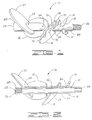
- Figure 1 is a perspective view of the device of the present invention.
- Figure 2 is a cross-sectional view of the device taken along line 2--2 of Figure 1.
- Figure 3 is an elevational view of the device of Figure 1 as seen from the first end.
- Figure 4 is an elevational view of the device of Figure 1 as seen from the second end.
- Figure 5 is a perspective view of the device of the present invention showing the positioning of the blades with respect to the body of the device.
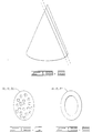
- Figure 6 is a perspective view of a cone illustrating the origin of one preferred blade configuration.
- Figure 7 is a plan view of one embodiment of the blades of the device of the present invention showing perforations in the blades.
- Figure 8 is a plan view of another embodiment of the blades of the device of the present invention showing a ring-shaped blade.
- Trenchless technology or the technology of boring underground without digging a trench, eliminates the need to excavate earth in order to lay a utility line, pipeline or other underground construction works. As such, the overburden remains undisturbed and need not be rehabilitated following completion of the job.
- a pilot bore is made underground along a planned path using a horizontal boring system.
- a variety of boring systems are available for making the pilot bore and one will be selected depending upon the conditions in which the installation is to take place, such as whether the soil is rocky or sandy, the length and diameter of the installation, the power needed to complete the installation and, the type of steering equipment and electronics required to determine the orientation and placement of the drill bit underground.
- the boring machine generally comprises a drill string made of a series of connected pipe joints. A drill bit is attached to the end of the drill string.
- the size of the bit selected depends upon the size of the pilot bore to be made, which in turn depends upon the size and type of utility or other line to be installed.
- the machine is operated to force the bit into the ground to drill the pilot bore in a generally arcuate path underneath the river. Additional lengths of pipe are added as needed to reach the exit point on the opposite shore of the river distant from the boring machine. The drill bit exits the earth at the exit point.
- the pilot bore is complete.
- a long, connected string of pipe lies in an arcuate path in the pilot bore underneath the river with the drill bit protruding at the exit point distant from the boring machine.
- the pilot bore then may be enlarged by replacing the drill bit with an enlarging device, commonly known as a backreamer.
- the backreamer is connected to the distal end of the drill string and moved through the pilot bore toward the boring machine, either with or without rotation of the drill string.
- the backreamer may be adapted to pull in a utility line or the like behind it as the string of drill pipe is moved in the reverse direction through the arcuate path back toward the boring machine.
- the backreamer expands the bore to the desired diameter and stabilizes the walls of the bore to create an environment in which a utility line can be pulled in behind the backreamer into place in the bore.
- backreamers are commercially available. Some conventional backreamers are conical in shape and are particularly suited for compressing compactible soils into the wall of the bore. These backreamers frequently are pulled without rotation through the pilot bore to compact the loose soil. Alternatively, other conventional cone-shaped backreamers comprise helical screw-style threads and are rotated while pulled through the pilot bore to enlarge the bore to the desired diameter.
- fluid is injected into the formation to create a slurry with the spoils, i.e. the cuttings, rocks, dirt and soil, produced during the reaming process.
- the cones function like hydraulic cylinders. The fluid flow and pressure must be reduced or shut off periodically to decrease the hydraulic pressure build up in the bore, causing time delays and expense.
- conventional backreamers are composed of a heavy metal alloy composition. These devices must be used with a machine capable of exerting significant pull back forces and, when rotating the drill string, greater torquing forces.
- the device of the present invention is uniquely constructed and designed to reduce the torque and power required to cut soil material loose during the reaming process, and thus increase the productivity, over conventional backreamers, but the device weighs approximately fifty percent less than conventional backreamers. Consequently, smaller boring machines capable of less torque and pullback forces are able to enlarge pilot bores to larger diameters using the device of the present invention. In some cases, small boring units using the present invention may enlarge bores during the reaming process up to at least 1.5 times larger than is possible using a conventional backreamer.
- the device of the present invention comprises a series of blades supported on a body so that the planes formed by the blades intersect.
- the blades cut the soil, enlarge the bore, disperse the cuttings, thoroughly mix the drilling fluid/soil slurry and stabilize the wall of the bore.
- the first blade cuts and increases the bore to the desired diameter.
- the following blades churn the soils to break up and disperse chunky cuttings, thus preventing the cuttings from sticking to the reamer, the utility line or the drill string in the bore.
- the following blades disperse sticky cuttings to prevent the downhole equipment from sticking in the bore and to minimize the torque required to free the equipment.
- the hind blades of the device of the present invention are particularly adapted to churn the spoils and break up large chunks of cuttings to make a smooth, even slurry, thus improving flowability of the slurry better lubrication for the utility and the drill string and a dramatic increase in the rate of penetration of the backreamer.
- the subject backreamer is particularly productive in clays, sandy soils and semi-hard materials.
- the device 10 generally comprises a body 12, cutting elements 14, a first blade 16, a second blade 18 and a third blade 20.
- the body 12 preferably is elongate and forms a structure or surface adapted to support the cutting elements 14 and the blades 16, 18 and 20. Generally, a cylinder or other elongate, structure is sufficient to meet this need. However, any body shape, structure or length able to support the elements of the invention in the desired order will suffice.
- the body preferably is hollow for a purpose yet to be described.
- the body 12 forms a first end 26 and second end 28, the first end 26 being operatively connectable to a string of drill pipe (not shown).
- the first end 26 is externally threadable, as shown in Figure 3, to the exposed, internally threaded pipe joint at the end of the drill string. It will be appreciated, however, that the first end 26 of the body 12 may be internally threaded or may be connectable to the drill string by any means sufficient to securely and operatively engage the device 10 with the drill string.
- the second end 28 of the body 12 may be plugged, as shown in Figure 4.
- a swivel or other device may be attached to the second end 28 of the body 12 to enable a utility line to be pulled in behind the device 10 in a manner yet to be described.
- the body 12 preferably is comprised of a sturdy, high tensile strength material, preferably a steel alloy. Although various materials may be used to build the body 12, a high-strength, low-alloy steel generally provides the necessary strength and durability to resist wear and abrasion and increase the life of the device 10. The device 10 thus maintains the strength and cutting power of steel; however, as explained herein, the unique design of the device decreases the weight of the device over conventional backreamers by about fifty percent while dramatically increasing productivity, efficiency and cutting power.
- the length and diameter of the body 12 of the device 10 depends upon the desired sized of the borehole, the horsepower and pullback capabilities of the boring unit, and the soil conditions at the site, among other factors.
- the body 12 When reaming large diameter bores, the body 12 must be of sufficient size and strength to support larger, heavier blades 16, 18 and 20 and cutting elements 14.
- the body 12 length ranges from about fifteen inches to about seventy inches, and the diameter of the body 12 ranges from about 2 inches to about 41 ⁇ 4 inches.
- the body 12 preferably forms a passageway 32 to channel fluid under pressure from the drill string through fluid jets 34 and forms a wall 36 having a thickness ranging generally from about 1 ⁇ 2 to about 3 ⁇ 4 inches thick. It will now be appreciated that the body 12 is hollow to permit the passage of fluid through the device 10 into the borehole.
- Fluid jets 34 are positioned near the cutting elements 14 and the blades 16, 18 and 20 in a manner yet to be described. In the preferred practice of the invention, at least three fluid jets 34 are positioned near blades 16, 18 and 20 and one fluid jet near each cutting element 14. The fluid from fluid jets 34 are sized and positioned to clean the blades 16, 18 and 20 and cutting elements 14 to create an adequate slurry in a manner and for purposes yet to be described.
- the device 10 preferably comprises a plurality of cutting elements 14.
- the cutting elements 14 are sized and positioned to make first contact with the walls of the pilot bore as the device 10 is moved through the pilot bore toward the boring machine and increases the diameter of the bore.
- the cutting elements 14 preferably are spaced circumferentially in one plane about the body 12 near the first end 26 of the device 10.
- three cutting elements 14 are supported circumferentially about the body 12 in one plane perpendicular to the axis of the body 12 and uniformly spaced about the body approximately 120° apart. The uniform spacing stabilizes the device 10 in the borehole and evenly distributes the cutting force of the cutting elements 14.
- the number and size of the cutting elements 14 may be increased or decreased to achieve a desired cutting pattern and efficiency and that the cutting elements may be positioned at other locations on the device 10 or in different planes of reference.
- the cutting elements 14 are of sturdy composition, preferably high gauge steel, and are supported on the device 10 by any means sufficient to secure the cutting elements to the body 12. Welding has proven an effective means of permanently attaching the cutting elements 14 to the body 12.
- the cutting elements 14 may be removably attached to the body 12 to permit repair and replacement as needed.
- the cutting elements 14 and the body 12 may be adapted to receive a bolt and nut assembly or other device adapted to removably secure the cutting elements to the body.
- the cutting elements 14 may be any shape, surface, configuration or structure adapted to contact the walls of the pilot bore and enlarge the bore to a selected intermediate or final diameter.
- claw-like structures provide a useful first cutting element 14.
- the cutting elements 14 gouge the walls of the bore and increase the bore diameter.
- a knife-edged, toothed or cylindrical surface or structure provide a few suitable alternatives. It will be appreciated that any device, surface, shape, configuration or structure which enlarges the bore will serve as a suitable cutting element 14.
- the size of the cutting elements 14 depends at least in part upon the desired final diameter of the borehole. In one preferred embodiment, the cutting elements 14 enlarge the bore to an intermediate diameter and, thereafter, the blade 16 enlarges the bore to the final diameter in a manner yet to be described. However, it will be appreciated that the cutting elements 14 may be sized to enlarge the bore to the final diameter or to any diameter in between the pilot bore diameter and the selected final bore size.
- the device 10 preferably further comprises a plurality of blades supported on the body 12.
- the plurality comprises three blades 16, 18 and 20; however, the number of blades may be increased or decreased depending upon various conditions, such as the type of soil at the construction site, the desired characteristics of the slurry and other factors.
- Each blade 16, 18 and 20 forms a plane x, y and z, respectively, and is positioned on the body 12 so that the planes of the blades intersect. While the blades 16, 18 and 20 may be mounted on the body 12 at any angle which causes the planes x, y and z to intersect, the mounting angle generally ranges from about 20° to about 70° with respect to the body 12.
- the blades 16, 18 and 20 are mounted on the body 12 so that the respective planes x, y and z form an angle of about 45° with respect to the body. It is not required that each blade intersect each plane of the other blades, but that the plane of each blade intersect with the plane formed by at least one the other blades.
- the shape of the blades 16, 18 and 20 may vary.
- the blades 16, 18 and 20 are generally ovate and derive their shape from the bisection of a cone, as illustrated in Figure 6.
- a conventional cone-shaped backreamer is sliced along two parallel lines, and the resulting bisection, which is generally ovate, provides the desired shape for the blades 16, 18 and 20 and produces surfaces 50, 52 and 54 which meet with edges 60, 62 and 64.
- the blades 16, 18 and 20 range generally from about 1 ⁇ 2 inch to about 11 ⁇ 4 inches in thickness and have a radius from about 6 inches to about 36 inches.
- other shapes such as triangular, square, circular and hexagonal, provide suitable alternative blade shapes. It will be appreciated that any shape which enables the blades to slice through soil and churn spoils provides a suitable blade shape for the device 10.
- the blades 16, 18 and 20 may be mounted to the body 12 so that the blades physically connect with each other or the blades may be separated, preferably with about at least six inches between mountings.
- the blades 16, 18 and 20 preferably are mounted to the body 12 through the surfaces 50, 52 and 54, respectively of the blades so that the body 12 bisects the blades.
- the blades 16, 18 and 20 may be mounted on the body at the edges 60, 62 and 64, respectively of the blades.
- welding is a preferred means for mounting the blades 16, 18 and 20 to the body 12.
- the blades 16, 18 and 20 may be mounted by any means sufficient to permanently or removably mount the blades to the body 12 and permit operation of the device 10.
- the blades 16, 18 and 20 may be adapted to removably mount the blades to enable repair and replacement of the blades without replacing the entire device.
- the blades 16, 18 and 20 preferably are mounted on the body 12 in a clockwise direction from the front side 66 to the back side 68 of the body 12 and from the first end 26 of the body to the second end 28 about 120 degrees apart. This spacing and positioning stabilizes the device 10 in the bore. It will be appreciated that this spacing and positioning of the blades may be varied to achieve a desired effect. For instance, the blades 16, 18 and 20 may be placed on the front side 40 of the device 10 or two blades may be supported on one side. However, a uniform spacing and positioning of the blades stabilizes the device 10 in the borehole and produces a more uniform bore.
- blade 16 is mounted on the body 12 between the second end 28 and the cutting elements 14, while blades 18 and 20 are mounted between the first blade and the second end 28 of the body.
- blade 16 proceeds through the bore before blades 18 and 20 and enlarges the bore to the final diameter.
- blade 16 preferably comprises an outer, arcuate leading edge 70 adapted to slice through soil, rock and other material from the wall of the bore to increase the diameter of the bore.
- the leading edge 70 may comprise a plurality of cutting teeth 72 or other sharp edge or cutting device adapted to cut material from and enlarge the bore.
- the angle at which blade 16 is mounted to the body 12, coupled with the unique blade configuration and the leading edge 70, enables blade 16 to slice through the soil and enlarge the bore to the final diameter. It will now be appreciated that the angular orientation of the blade 16 enables the leading edge 70 to slice through the bore wall and direct cuttings toward the second end 28 of the device 10.
- the cutting teeth 72 or other cutting device may be permanently mounted to blade 16 by welding or other means or adapted to be removed for repair and replacement.
- Blades 18 and 20 are mounted between the blade 16 and the second end 28 of the body 12. Blades 18 and 20 maintain the position of the device 10 in the borehole and churn the spoils created by blade 16. Blades 18 and 20 may form solid plates or may be perforated or dimpled to enhance the churning capabilities and thereby increase productivity. Perforated blades, shown in Figure 7, and "O-ring" shaped blades, shown in Figure 8, are some acceptable alternative embodiments of blades 16, 18 and 20. The churning capabilities of blades 18 and 20 have proven particularly useful in sticky soils and clays. Blades 18 and 20 actively mix spoils so that the spoils are suspended in the fluid from the jets, eliminate large chunks of soil, and mix a slurry with improved fluidity, solids suspension and lubrication characteristics.
- fluid jets 34 are positioned on the body 12 of the device 10 adjacent the cutting elements 14 and each blade 16, 18 and 20.
- thirteen fluid jets 34 are supported on the body 12.
- Three fluid jets 34 are positioned in front of the cutting elements 14.
- Four fluid jets 34 are positioned near blade 16, one of which is in front of the leading edge 70 to force spoils over the blade 16 toward the second end 28 of the device 10.
- Three fluid jets 34 are positioned near each blade 18 and 20.
- the fluid jets near the blades 16, 18 and 20 are angled transversely with respect to the surface of the body 12 and are directed at the blades to clean the blades during the reaming operation.
- the fluid from fluid jets 34 deflects off of the blades 16, 18 and 20 and mixes with the spoils to create a slurry and lubricate the equipment in the bore.
- the present invention also comprises a method for enlarging a bore.
- a boring site is selected and a suitable boring machine assembled.
- the length and diameter of the borehole as well as the conditions of the terrain are considered in selecting the size and type of boring head, the length and diameter of pipe joints and the size of the machine.
- the boring operation is commenced in a known manner.
- additional pipe joints are added. Boring proceeds along a predetermined path until the boring head emerges from the earth at an exit point.
- the device 10 may be connected to the last pipe in the drill string.
- the boring machine is then operated and the drill string rotated and removed while pulling the device 10 through the bore to ream the bore to the desired diameter.
- fluid is circulated through the drill pipe and out of the fluid jets 34 of the device 10 to lubricate, create a slurry, compact the walls of the borehole, increase the fluidity of the slurry and keep the blades clean of spoils.
- the cutting elements 14 make first contact with the walls of the pilot bore and initially ream the bore to a predetermined intermediate diameter.
- blade 16 enlarges the bore to the final desired diameter. It will now be appreciated that the leading edge 70 of blade 16 enlarges the bore and blades 18 and 20 stabilize the device 10 in the borehole and churn the spoils making a slurry.
- the slurry forms a filter cake on the wall of the bore to help prevent collapse of the wall on the equipment.
- the present invention further is directed to a method for installing and constructing utility lines, pipe lines, cables and the like.
- the method of enlarging a borehole, described above, is employed, and a swivel is attached to the second end 28 of the body 12.
- the utility line is connected to the swivel.
- the utility line is pulled in behind the device 10 into place in the borehole.
- the present invention provides an improved device for enlarging a bore.
- the device 10 of the present invention maintains the strength and cutting ability of conventional backreamers; however, the unique design and construction of the device decreases the weight of the device over conventional backreamers by about fifty percent while increasing productivity, efficiency and cutting ability.
- the cutting elements 14 of the device 10 make initial contact with the bore, while blade 16 enlarges the bore to the final diameter. Blades 18 and 20 churn the spoils stabilize the device 10 within the bore.
- the unique construction and configuration of the device and its elements results in a backreamer more than by fifty percent lighter in weight than conventional backreamers.
- productivity is significantly increased as the penetration rate can jump from ten feet in five to seven minutes using a conventional backreamer to about ten feet in one minute using the device of the present invention.
- the device 10 eliminates large chunks of cuttings, mixes the fluid with spoils to make a slurry with improved fluidity, improves suspension of cuttings in the slurry, lubricates the device and the utility pulled in behind the device, and a dramatically increases penetration rate.
- This device has proven particularly productive in clay soils and other soils which tend to clump and hinder the reaming process.
Abstract
Description
- The present invention relates generally to devices for enlarging bores and particularly to backreaming devices used in the horizontal boring industry. The present invention further relates to methods of enlarging a borehole and installing and constructing utility lines, pipe lines and the like.
- The present invention is directed to a device for making or enlarging a bore. The device comprises an elongate body connectable to a source for moving the device through the bore and a plurality of blades, each blade defining a plane. The blades are supported on the body so that the planes of the blades intersect.
- The present invention further is directed to a method for enlarging a bore using a boring machine adapted to bore a pilot bore in the earth from a point of entry to an exit point distant from the boring machine. The method comprises the steps of connecting an enlarging device to the distal end of the boring machine, the enlarging device comprising an elongate body connectable to a source for moving the device through the bore and a plurality of blades, each blade defining a plane, wherein the blades are supported on the body so that the planes of the blades intersect, and moving the enlarging device through the bore in a manner to enlarge the bore.
- Finally the present invention is directed to a method for installing utility lines and the like by using a boring machine adapted to bore a pilot bore in the earth from a point of entry to an exit point distant from the boring machine. The method comprises the steps of connecting an enlarging device to the distal end of the boring machine, the enlarging device comprising an elongate body connectable to a source for moving the device through the bore and a plurality of blades, each blade defining a plane, wherein the blades are supported on the body so that the planes of the blades intersect, moving the enlarging device through the bore in a manner to enlarge the bore, and simultaneously pulling in the utility line into the bore while moving the enlarging device through the bore.
- Figure 1 is a perspective view of the device of the present invention.
- Figure 2 is a cross-sectional view of the device taken along line 2--2 of Figure 1.
- Figure 3 is an elevational view of the device of Figure 1 as seen from the first end.
- Figure 4 is an elevational view of the device of Figure 1 as seen from the second end.
- Figure 5 is a perspective view of the device of the present invention showing the positioning of the blades with respect to the body of the device.
- Figure 6 is a perspective view of a cone illustrating the origin of one preferred blade configuration.
- Figure 7 is a plan view of one embodiment of the blades of the device of the present invention showing perforations in the blades.
- Figure 8 is a plan view of another embodiment of the blades of the device of the present invention showing a ring-shaped blade.
- Over the last decade, trenchless technology has been overtaking the market for the construction of underground utilities. Trenchless technology, or the technology of boring underground without digging a trench, eliminates the need to excavate earth in order to lay a utility line, pipeline or other underground construction works. As such, the overburden remains undisturbed and need not be rehabilitated following completion of the job.
- In the typical underground utility installation employing trenchless technology, a pilot bore is made underground along a planned path using a horizontal boring system. A variety of boring systems are available for making the pilot bore and one will be selected depending upon the conditions in which the installation is to take place, such as whether the soil is rocky or sandy, the length and diameter of the installation, the power needed to complete the installation and, the type of steering equipment and electronics required to determine the orientation and placement of the drill bit underground. For example, if a telephone line is to be laid underneath a river, a boring machine having the necessary power and equipment is placed on one side of the river at the earth entry point. The boring machine generally comprises a drill string made of a series of connected pipe joints. A drill bit is attached to the end of the drill string. The size of the bit selected depends upon the size of the pilot bore to be made, which in turn depends upon the size and type of utility or other line to be installed. The machine is operated to force the bit into the ground to drill the pilot bore in a generally arcuate path underneath the river. Additional lengths of pipe are added as needed to reach the exit point on the opposite shore of the river distant from the boring machine. The drill bit exits the earth at the exit point.
- At this point in the installation process, the pilot bore is complete. A long, connected string of pipe lies in an arcuate path in the pilot bore underneath the river with the drill bit protruding at the exit point distant from the boring machine. The pilot bore then may be enlarged by replacing the drill bit with an enlarging device, commonly known as a backreamer. The backreamer is connected to the distal end of the drill string and moved through the pilot bore toward the boring machine, either with or without rotation of the drill string. The backreamer may be adapted to pull in a utility line or the like behind it as the string of drill pipe is moved in the reverse direction through the arcuate path back toward the boring machine. The backreamer expands the bore to the desired diameter and stabilizes the walls of the bore to create an environment in which a utility line can be pulled in behind the backreamer into place in the bore.
- Various backreamers are commercially available. Some conventional backreamers are conical in shape and are particularly suited for compressing compactible soils into the wall of the bore. These backreamers frequently are pulled without rotation through the pilot bore to compact the loose soil. Alternatively, other conventional cone-shaped backreamers comprise helical screw-style threads and are rotated while pulled through the pilot bore to enlarge the bore to the desired diameter.
- Frequently, fluid is injected into the formation to create a slurry with the spoils, i.e. the cuttings, rocks, dirt and soil, produced during the reaming process. When fluid is used in association with conventional cone-shaped backreamers, the cones function like hydraulic cylinders. The fluid flow and pressure must be reduced or shut off periodically to decrease the hydraulic pressure build up in the bore, causing time delays and expense.
- Further, in order to accomplish the objective of enlarging the pilot bore and stabilizing the walls, conventional backreamers are composed of a heavy metal alloy composition. These devices must be used with a machine capable of exerting significant pull back forces and, when rotating the drill string, greater torquing forces.
- The device of the present invention is uniquely constructed and designed to reduce the torque and power required to cut soil material loose during the reaming process, and thus increase the productivity, over conventional backreamers, but the device weighs approximately fifty percent less than conventional backreamers. Consequently, smaller boring machines capable of less torque and pullback forces are able to enlarge pilot bores to larger diameters using the device of the present invention. In some cases, small boring units using the present invention may enlarge bores during the reaming process up to at least 1.5 times larger than is possible using a conventional backreamer.
- The device of the present invention comprises a series of blades supported on a body so that the planes formed by the blades intersect. As the backreamer is pulled and rotated through the pilot bore, the blades cut the soil, enlarge the bore, disperse the cuttings, thoroughly mix the drilling fluid/soil slurry and stabilize the wall of the bore. The first blade cuts and increases the bore to the desired diameter. The following blades churn the soils to break up and disperse chunky cuttings, thus preventing the cuttings from sticking to the reamer, the utility line or the drill string in the bore. The following blades disperse sticky cuttings to prevent the downhole equipment from sticking in the bore and to minimize the torque required to free the equipment. The hind blades of the device of the present invention are particularly adapted to churn the spoils and break up large chunks of cuttings to make a smooth, even slurry, thus improving flowability of the slurry better lubrication for the utility and the drill string and a dramatic increase in the rate of penetration of the backreamer. The subject backreamer is particularly productive in clays, sandy soils and semi-hard materials. These and other advantages of the present invention will be apparent from the following description of the preferred embodiments.
- Turning now to the drawings in general and to Figures 1 and 2, in particular, there is shown therein a
device 10 for enlarging boreholes and constructed in accordance with the present invention. Thedevice 10 generally comprises abody 12,cutting elements 14, afirst blade 16, asecond blade 18 and athird blade 20. - The
body 12 preferably is elongate and forms a structure or surface adapted to support thecutting elements 14 and theblades - Ordinarily, in the horizontal boring process, successive lengths of drill pipe are added to the drill pipe sections as the boring process progresses and the bit drills farther along the planned path to the exit point. At the exit point, the drill bit will be removed exposing a pipe joint to which the device. 10 is attachable. To that end, the
body 12 forms afirst end 26 andsecond end 28, thefirst end 26 being operatively connectable to a string of drill pipe (not shown). In one preferred embodiment, thefirst end 26 is externally threadable, as shown in Figure 3, to the exposed, internally threaded pipe joint at the end of the drill string. It will be appreciated, however, that thefirst end 26 of thebody 12 may be internally threaded or may be connectable to the drill string by any means sufficient to securely and operatively engage thedevice 10 with the drill string. - The
second end 28 of thebody 12 may be plugged, as shown in Figure 4. Alternatively, a swivel or other device may be attached to thesecond end 28 of thebody 12 to enable a utility line to be pulled in behind thedevice 10 in a manner yet to be described. - With continuing reference to Figure 1, the
body 12 preferably is comprised of a sturdy, high tensile strength material, preferably a steel alloy. Although various materials may be used to build thebody 12, a high-strength, low-alloy steel generally provides the necessary strength and durability to resist wear and abrasion and increase the life of thedevice 10. Thedevice 10 thus maintains the strength and cutting power of steel; however, as explained herein, the unique design of the device decreases the weight of the device over conventional backreamers by about fifty percent while dramatically increasing productivity, efficiency and cutting power. - The length and diameter of the
body 12 of thedevice 10 depends upon the desired sized of the borehole, the horsepower and pullback capabilities of the boring unit, and the soil conditions at the site, among other factors. When reaming large diameter bores, thebody 12 must be of sufficient size and strength to support larger,heavier blades elements 14. Typically, thebody 12 length ranges from about fifteen inches to about seventy inches, and the diameter of thebody 12 ranges from about 2 inches to about 4¼ inches. - Turning now to Figure 2, the
body 12 preferably forms apassageway 32 to channel fluid under pressure from the drill string throughfluid jets 34 and forms awall 36 having a thickness ranging generally from about ½ to about ¾ inches thick. It will now be appreciated that thebody 12 is hollow to permit the passage of fluid through thedevice 10 into the borehole.Fluid jets 34 are positioned near the cuttingelements 14 and theblades fluid jets 34 are positioned nearblades element 14. The fluid fromfluid jets 34 are sized and positioned to clean theblades elements 14 to create an adequate slurry in a manner and for purposes yet to be described. - With continuing reference to Figures 1 and 2, the
device 10 preferably comprises a plurality of cuttingelements 14. The cuttingelements 14 are sized and positioned to make first contact with the walls of the pilot bore as thedevice 10 is moved through the pilot bore toward the boring machine and increases the diameter of the bore. For this purpose, the cuttingelements 14 preferably are spaced circumferentially in one plane about thebody 12 near thefirst end 26 of thedevice 10. In one preferred embodiment, illustrated in Figure 3, three cuttingelements 14 are supported circumferentially about thebody 12 in one plane perpendicular to the axis of thebody 12 and uniformly spaced about the body approximately 120° apart. The uniform spacing stabilizes thedevice 10 in the borehole and evenly distributes the cutting force of the cuttingelements 14. It will be appreciated that the number and size of the cuttingelements 14 may be increased or decreased to achieve a desired cutting pattern and efficiency and that the cutting elements may be positioned at other locations on thedevice 10 or in different planes of reference. The cuttingelements 14 are of sturdy composition, preferably high gauge steel, and are supported on thedevice 10 by any means sufficient to secure the cutting elements to thebody 12. Welding has proven an effective means of permanently attaching the cuttingelements 14 to thebody 12. The cuttingelements 14 may be removably attached to thebody 12 to permit repair and replacement as needed. For this purpose, the cuttingelements 14 and thebody 12 may be adapted to receive a bolt and nut assembly or other device adapted to removably secure the cutting elements to the body. - With continuing reference to Figures 1, 2 and 3, the cutting
elements 14 may be any shape, surface, configuration or structure adapted to contact the walls of the pilot bore and enlarge the bore to a selected intermediate or final diameter. In one preferred embodiment, claw-like structures provide a usefulfirst cutting element 14. As thedevice 10 is rotated clockwise, the cuttingelements 14 gouge the walls of the bore and increase the bore diameter. A knife-edged, toothed or cylindrical surface or structure provide a few suitable alternatives. It will be appreciated that any device, surface, shape, configuration or structure which enlarges the bore will serve as asuitable cutting element 14. - The size of the cutting
elements 14 depends at least in part upon the desired final diameter of the borehole. In one preferred embodiment, the cuttingelements 14 enlarge the bore to an intermediate diameter and, thereafter, theblade 16 enlarges the bore to the final diameter in a manner yet to be described. However, it will be appreciated that the cuttingelements 14 may be sized to enlarge the bore to the final diameter or to any diameter in between the pilot bore diameter and the selected final bore size. - Turning now to Figure 5, the
device 10 preferably further comprises a plurality of blades supported on thebody 12. In one preferred embodiment, the plurality comprises threeblades blade body 12 so that the planes of the blades intersect. While theblades body 12 at any angle which causes the planes x, y and z to intersect, the mounting angle generally ranges from about 20° to about 70° with respect to thebody 12. In one preferred embodiment, theblades body 12 so that the respective planes x, y and z form an angle of about 45° with respect to the body. It is not required that each blade intersect each plane of the other blades, but that the plane of each blade intersect with the plane formed by at least one the other blades. - The shape of the
blades blades blades surfaces edges blades device 10. - Returning to Figures 3, 4 and 5, the
blades body 12 so that the blades physically connect with each other or the blades may be separated, preferably with about at least six inches between mountings. Theblades body 12 through thesurfaces body 12 bisects the blades. Alternatively, theblades edges - Welding is a preferred means for mounting the
blades body 12. However, it will be appreciated that theblades body 12 and permit operation of thedevice 10. For example, theblades - With continuing reference to Figures 1 through 5, the
blades body 12 in a clockwise direction from thefront side 66 to theback side 68 of thebody 12 and from thefirst end 26 of the body to thesecond end 28 about 120 degrees apart. This spacing and positioning stabilizes thedevice 10 in the bore. It will be appreciated that this spacing and positioning of the blades may be varied to achieve a desired effect. For instance, theblades device 10 or two blades may be supported on one side. However, a uniform spacing and positioning of the blades stabilizes thedevice 10 in the borehole and produces a more uniform bore. - In the preferred practice of the invention,
blade 16 is mounted on thebody 12 between thesecond end 28 and the cuttingelements 14, whileblades second end 28 of the body. During operation of thedevice 10,blade 16 proceeds through the bore beforeblades blade 16 preferably comprises an outer, arcuate leadingedge 70 adapted to slice through soil, rock and other material from the wall of the bore to increase the diameter of the bore. The leadingedge 70 may comprise a plurality of cuttingteeth 72 or other sharp edge or cutting device adapted to cut material from and enlarge the bore. The angle at whichblade 16 is mounted to thebody 12, coupled with the unique blade configuration and the leadingedge 70, enablesblade 16 to slice through the soil and enlarge the bore to the final diameter. It will now be appreciated that the angular orientation of theblade 16 enables the leadingedge 70 to slice through the bore wall and direct cuttings toward thesecond end 28 of thedevice 10. The cuttingteeth 72 or other cutting device may be permanently mounted toblade 16 by welding or other means or adapted to be removed for repair and replacement. -
Blades blade 16 and thesecond end 28 of thebody 12.Blades device 10 in the borehole and churn the spoils created byblade 16.Blades blades blades Blades - Referring again to Figures 1 and 2, it now will be appreciated that the
blades blade 16 and the fluid injected into the bore byfluid jets 34. To accomplish that purpose,fluid jets 34 are positioned on thebody 12 of thedevice 10 adjacent the cuttingelements 14 and eachblade fluid jets 34 are supported on thebody 12. Threefluid jets 34 are positioned in front of the cuttingelements 14. Fourfluid jets 34 are positioned nearblade 16, one of which is in front of the leadingedge 70 to force spoils over theblade 16 toward thesecond end 28 of thedevice 10. Threefluid jets 34 are positioned near eachblade blades body 12 and are directed at the blades to clean the blades during the reaming operation. The fluid fromfluid jets 34 deflects off of theblades - The present invention also comprises a method for enlarging a bore. In accordance with the method of the present invention, a boring site is selected and a suitable boring machine assembled. The length and diameter of the borehole as well as the conditions of the terrain are considered in selecting the size and type of boring head, the length and diameter of pipe joints and the size of the machine.
- Having the selected the site and assembled a suitable machine, the boring operation is commenced in a known manner. As the borehole increases in length, additional pipe joints are added. Boring proceeds along a predetermined path until the boring head emerges from the earth at an exit point. At this point, the
device 10 may be connected to the last pipe in the drill string. The boring machine is then operated and the drill string rotated and removed while pulling thedevice 10 through the bore to ream the bore to the desired diameter. As thedevice 10 is rotated, fluid is circulated through the drill pipe and out of thefluid jets 34 of thedevice 10 to lubricate, create a slurry, compact the walls of the borehole, increase the fluidity of the slurry and keep the blades clean of spoils. As thedevice 10 is moved through the pilot bore and rotated, the cuttingelements 14 make first contact with the walls of the pilot bore and initially ream the bore to a predetermined intermediate diameter. After the bore has been enlarged by the cuttingelements 14,blade 16 enlarges the bore to the final desired diameter. It will now be appreciated that the leadingedge 70 ofblade 16 enlarges the bore andblades device 10 in the borehole and churn the spoils making a slurry. The slurry forms a filter cake on the wall of the bore to help prevent collapse of the wall on the equipment. - The present invention further is directed to a method for installing and constructing utility lines, pipe lines, cables and the like. The method of enlarging a borehole, described above, is employed, and a swivel is attached to the
second end 28 of thebody 12. The utility line is connected to the swivel. As thedevice 10 is moved through the bore behind the drill string the utility line is pulled in behind thedevice 10 into place in the borehole. - Now it will be appreciated that the present invention provides an improved device for enlarging a bore. The
device 10 of the present invention maintains the strength and cutting ability of conventional backreamers; however, the unique design and construction of the device decreases the weight of the device over conventional backreamers by about fifty percent while increasing productivity, efficiency and cutting ability. The cuttingelements 14 of thedevice 10 make initial contact with the bore, whileblade 16 enlarges the bore to the final diameter.Blades device 10 within the bore. The unique construction and configuration of the device and its elements results in a backreamer more than by fifty percent lighter in weight than conventional backreamers. Yet, productivity is significantly increased as the penetration rate can jump from ten feet in five to seven minutes using a conventional backreamer to about ten feet in one minute using the device of the present invention. Thedevice 10 eliminates large chunks of cuttings, mixes the fluid with spoils to make a slurry with improved fluidity, improves suspension of cuttings in the slurry, lubricates the device and the utility pulled in behind the device, and a dramatically increases penetration rate. This device has proven particularly productive in clay soils and other soils which tend to clump and hinder the reaming process. - Changes may be made in the combination and arrangements of the various parts, elements, steps and procedures described herein, without departing from the spirit and scope of the invention as defined in the following claims.
Claims (45)
- A device for making or enlarging a bore, the device comprising:an elongate body connectable to a source for moving the device through the bore;a plurality of blades, each blade defining a plane;wherein the blades are supported on the body so that the planes of the blades intersect.
- The device of claim 1 wherein the blades are comprised of steel.
- The device of claim 1 wherein the body defines a first end and a second end and wherein the blades are circumferentially supported on the body in a clockwise direction from the first end to the second end and are spaced about 120° apart about the circumference of the body.
- The device of claim 1 wherein the blades are supported on the body at an angle of about 20° to about 70° with respect to the body.
- The device of claim 1 wherein the body defines a passage adapted to transmit fluid through the body.
- The device of claim 1 wherein the body comprises a shaft having a first end and a second end and wherein the first end is threadably connectable to the source for driving the movement of the device.
- The device of claim 6 wherein the second end comprises a plug.
- The device of claim 6 wherein the second end is adapted to be connected to device for pulling in a utility line or the like.
- The device of claim 1 wherein the blade is generally ovate.
- The device of claim 1 wherein:the body forms a first end and a second end;the plurality of blades comprises a first blade supported near the first end of the body; andthe first blade is characterized by the ability to enlarge the bore.
- The device of claim 10 wherein the first blade further comprises an edge adapted to cut the wall of the bore.
- The device of claim 10 wherein the edge further comprises a plurality of cutting teeth adapted to cut the wall of the bore.
- The device of claim 10 wherein the plurality of blades further comprise a second blade and a third blade supported on the body between the first blade and the second end of the body, the second and third blades being characterized by the ability to churn spoils.
- The device of claim 1 wherein at least one of the blades is perforated.
- The device of claim 1 wherein at least one of the blades is ring-shaped.
- The device of claim 1 further comprising at least one cutting element supported on the body near the first end and adapted to make first contact with the walls of the bore and enlarge the bore as the device is moved through the bore.
- The device of claim 16 wherein the cutting element is claw-shaped.
- The device of claim 16 further comprising a plurality of cutting elements spaced around the circumference of the body about 120° apart.
- The device of claim 18 wherein the plurality of cutting elements are supported on the body in the same plane.
- The device of claim 1 wherein the device further comprises a fluid jet.
- The device of claim 20 further comprising a plurality of fluid jets, wherein at least one of the fluid jets is adapted to direct fluid at the blades.
- The device of claim 1 wherein the blades are from about ½ inch thick to about 1¼ inches thick.
- The device of claim 1 wherein the blades have a radius from about 6 inches to about 36 inches.
- The device of claim 1 wherein the body has a length from about 15 inches to about 70 inches.
- The device of claim 1 wherein the body is comprised of steel.
- The device of claim 19 wherein the cutting elements are sized to enlarge the bore to an intermediate diameter.
- The device of claim 10 wherein the first blade is sized to enlarge the bore to a final diameter.
- The device of claim 1 further comprising a mounting assembly adapted to removably mount the blades to the device.
- The device of claim 16 further comprising a mounting assembly adapted to removably mount the cutting elements to the device.
- The device of claim 12 further comprising a mounting assembly adapted to removably mount the cutting teeth to the first blade.
- The device of claim 1 or the method of claims 33 or 38 wherein each blade is supported on the body so that the body dissects the blade.
- The device of claim 12 wherein the blades are comprised of steel.
- A method for enlarging a bore using a boring machine adapted to bore a pilot bore in the earth from a point of entry to an exit point distant from the boring machine, the method comprising the steps of:connecting an enlarging device to the distal end of the boring machine, the enlarging device comprising an elongate body connectable to a source for moving the device through the bore and a plurality of blades, each blade defining a plane, wherein the blades are supported on the body so that the planes of the blades intersect.moving the enlarging device through the bore in a manner to enlarge the bore.
- The method of claim 33 wherein the step of moving the enlarging device through the bore further comprises the step of rotating the enlarging device while simultaneously pulling the enlarging device through the bore toward the boring machine.
- The method of claim 33 further comprising the step of mixing a slurry while moving the device through the bore.
- The method of claim 33 further comprising the step of directing fluid through the device toward each blade to clean each blade while moving the device through the bore.
- The method of claim 33 wherein the step of enlarging the bore further comprises the steps of enlarging the bore first to an intermediate diameter and then to a final diameter.
- A method for installing utility lines and the like by using a boring machine adapted to bore a pilot bore in the earth from a point of entry to an exit point distant from the boring machine, the method comprising the steps of:connecting an enlarging device to the distal end of the boring machine, the enlarging device comprising an elongate body connectable to a source for moving the device through the bore and a plurality of blades, each blade defining a plane, wherein the blades are supported on the body so that the planes of the blades intersect.moving the enlarging device through the bore in a manner to enlarge the bore; andsimultaneously pulling in the utility line into the bore while moving the enlarging device through the bore.
- The method of claim 38 wherein the step of moving the enlarging device through the bore further comprises the step of rotating the enlarging device while simultaneously pulling the enlarging device through the bore toward the boring machine.
- The method of claim 38 further comprising the simultaneous step of mixing a slurry while moving the device through the bore.
- The method of claim 38 further comprising the step of directing fluid through the device toward each blade to clean each blade while moving the device through the bore.
- The method of claim 38 wherein the step of enlarging the bore further comprises the steps of enlarging the bore first to an intermediate diameter and then to a final diameter.
- The method of claim 38 further comprising the step of connecting a swivel to the device and to the utility line to be pulled in before moving the device through the bore.
- A device for making or enlarging a borehole, the device comprising:an elongate body connectable to a source for moving the device through the bore;a plurality of blades, each blade defining a plane, wherein the blades are supported on the body so that the planes of the blades intersect; andat least one cutting element supported on the body near the first end of the body and adapted to make first contact with the walls of the bore and enlarge the bore as the device is moved through the bore;wherein the plurality of blades comprises a first blade characterized by the ability to enlarge the bore and second and third blades characterized by the ability to churn spoils.
- A blade for a device for making or enlarging a bore, the device comprising an elongate body connectable to a source for moving the device through the bore and a plurality of blades, each blade defining a plane, wherein the blades are supported on the body so that the planes of the blades intersect, the blade comprising:a plate adapted to enlarge the bore to a desired diameter.
Applications Claiming Priority (2)
| Application Number | Priority Date | Filing Date | Title |
|---|---|---|---|
| US08/940,385 US6250403B1 (en) | 1997-09-30 | 1997-09-30 | Device and method for enlarging a Bore |
| US940385 | 1997-09-30 |
Publications (2)
| Publication Number | Publication Date |
|---|---|
| EP0905347A2 true EP0905347A2 (en) | 1999-03-31 |
| EP0905347A3 EP0905347A3 (en) | 2000-12-06 |
Family
ID=25474726
Family Applications (1)
| Application Number | Title | Priority Date | Filing Date |
|---|---|---|---|
| EP98307866A Withdrawn EP0905347A3 (en) | 1997-09-30 | 1998-09-28 | Device and method for enlarging a bore |
Country Status (2)
| Country | Link |
|---|---|
| US (1) | US6250403B1 (en) |
| EP (1) | EP0905347A3 (en) |
Cited By (4)
| Publication number | Priority date | Publication date | Assignee | Title |
|---|---|---|---|---|
| WO2002035050A1 (en) * | 2000-10-27 | 2002-05-02 | Tracto-Technik Gmbh | Device for producing a peripheral hole |
| DE10144973A1 (en) * | 2001-09-12 | 2003-04-10 | Tracto Technik | Tool for reaming/scraping underground pipeline channels has scraper blades forming hollow chambers, which are fed with a drilling medium for delivery through jets at the blades |
| US6668946B2 (en) | 2001-01-22 | 2003-12-30 | Vermeer Manufacturing Company | Backreamer |
| CN107387012A (en) * | 2017-08-11 | 2017-11-24 | 山东科瑞井控系统制造有限公司 | It is a kind of with Yu Haiyang and the reaming tool of situ of drilling well on land well head |
Families Citing this family (19)
| Publication number | Priority date | Publication date | Assignee | Title |
|---|---|---|---|---|
| US6659198B2 (en) | 2001-06-20 | 2003-12-09 | S & S Trust | Back reamer assembly |
| US6810973B2 (en) | 2002-02-08 | 2004-11-02 | Hard Rock Drilling & Fabrication, L.L.C. | Steerable horizontal subterranean drill bit having offset cutting tooth paths |
| US6827159B2 (en) | 2002-02-08 | 2004-12-07 | Hard Rock Drilling & Fabrication, L.L.C. | Steerable horizontal subterranean drill bit having an offset drilling fluid seal |
| US6810971B1 (en) | 2002-02-08 | 2004-11-02 | Hard Rock Drilling & Fabrication, L.L.C. | Steerable horizontal subterranean drill bit |
| US6814168B2 (en) | 2002-02-08 | 2004-11-09 | Hard Rock Drilling & Fabrication, L.L.C. | Steerable horizontal subterranean drill bit having elevated wear protector receptacles |
| US6810972B2 (en) | 2002-02-08 | 2004-11-02 | Hard Rock Drilling & Fabrication, L.L.C. | Steerable horizontal subterranean drill bit having a one bolt attachment system |
| US6682264B1 (en) * | 2002-02-26 | 2004-01-27 | Ina Acquisition Corp. | Method of accurate trenchless installation of underground pipe |
| US6929078B1 (en) | 2002-11-21 | 2005-08-16 | Astec Industries, Inc. | Apparatus for use in enlarging a borehole |
| US7243737B2 (en) * | 2004-09-22 | 2007-07-17 | Vermeer Manufacturing Company | Interchangeable reamer |
| US9828805B2 (en) * | 2013-04-10 | 2017-11-28 | The Charles Machine Works, Inc. | Reamer with replaceable cutters |
| US10619420B2 (en) | 2013-05-20 | 2020-04-14 | The Charles Machine Works, Inc. | Reamer with replaceable rolling cutters |
| US9719344B2 (en) | 2014-02-14 | 2017-08-01 | Melfred Borzall, Inc. | Direct pullback devices and method of horizontal drilling |
| US10036205B2 (en) | 2015-06-04 | 2018-07-31 | The Charles Machine Works, Inc. | Stacked-plate reamer |
| US10301880B2 (en) | 2015-09-25 | 2019-05-28 | Radius Hdd Direct, Llc | Over-bit reamer |
| RU2636662C1 (en) * | 2016-10-21 | 2017-11-27 | Александр Израилевич Ентель | Method of controlled well making without excavation |
| RU173195U1 (en) * | 2017-05-22 | 2017-08-16 | Александр Израилевич Ентель | Device for driving a well without excavation |
| RU2668119C1 (en) * | 2017-10-05 | 2018-09-26 | Александр Израилевич Ентель | Device for drilling wells without excavation |
| RU177314U1 (en) * | 2017-10-05 | 2018-02-15 | Александр Израилевич Ентель | DEVICE FOR DRILLING WELL WITHOUT DIGGING |
| US11629556B2 (en) | 2018-02-23 | 2023-04-18 | Melfred Borzall, Inc. | Directional drill bit attachment tools and method |
Citations (16)
| Publication number | Priority date | Publication date | Assignee | Title |
|---|---|---|---|---|
| NL26951C (en) * | 1900-01-01 | |||
| US1494274A (en) * | 1921-08-02 | 1924-05-13 | James G Morgan | Expansion coal cutter |
| GB247473A (en) * | 1925-08-13 | 1926-02-18 | Lester Clay Black | Improvements in or relating to rotary drill bits |
| US1582283A (en) * | 1922-09-19 | 1926-04-27 | Edward K Lane | Well-drilling tool |
| US1667155A (en) * | 1927-03-18 | 1928-04-24 | Zalmon B Higdon | Drilling bit |
| US1987291A (en) * | 1932-02-20 | 1935-01-08 | Gliwitzki Guillermo | Combined widening and guiding tool for boring wells |
| US2365941A (en) * | 1942-08-31 | 1944-12-26 | Shell Dev | Oil well drill bit |
| US2830795A (en) * | 1956-11-30 | 1958-04-15 | Jr Edwin B Center | Well drilling bit |
| US3162257A (en) * | 1962-10-12 | 1964-12-22 | Newton E Noyes | Barrel-type soil auger |
| US3967689A (en) * | 1974-09-25 | 1976-07-06 | Tidril Corporation | Reaming apparatus |
| FR2587630A1 (en) * | 1985-09-20 | 1987-03-27 | Bourlier Manutention | Disintegrator tool |
| US4915182A (en) * | 1988-07-01 | 1990-04-10 | Hilti Aktiengesellschaft | Cutter elements for hollow drill bit |
| US5174374A (en) * | 1991-10-17 | 1992-12-29 | Hailey Charles D | Clean-out tool cutting blade |
| US5303787A (en) * | 1991-05-23 | 1994-04-19 | Brady William J | Rotary mining tools |
| US5351764A (en) * | 1990-07-26 | 1994-10-04 | Cherrington Corporation | Method and apparatus for enlarging an underground path |
| US5641027A (en) * | 1995-01-09 | 1997-06-24 | Utd Incorporated | Drilling system |
Family Cites Families (25)
| Publication number | Priority date | Publication date | Assignee | Title |
|---|---|---|---|---|
| US269548A (en) | 1882-12-26 | William stephenson | ||
| US1937742A (en) | 1931-05-09 | 1933-12-05 | Brink Mehl Oran | Reamer for well drills |
| US3710523A (en) * | 1971-08-03 | 1973-01-16 | J Taylor | Earth anchor |
| FR2207872B1 (en) | 1972-11-28 | 1976-04-23 | Sogreah | |
| US3898895A (en) | 1974-01-14 | 1975-08-12 | Thomas L Taylor | Method of attaching teeth to an earth drilling tool |
| US4121668A (en) * | 1976-06-29 | 1978-10-24 | Detroit Tool & Engineering Co. | Motor-driven cultivator with counter-rotating auger shafts |
| US4266830A (en) | 1977-07-21 | 1981-05-12 | The United States Of America As Represented By The Secretary Of The Interior | Auger construction providing reduced noise |
| US4248314A (en) | 1979-05-29 | 1981-02-03 | Hughes Tool Company | Shaft drill bit with overlapping cutter arrangement |
| US4467575A (en) | 1983-06-09 | 1984-08-28 | A. B. Chance Company | Internally driven earth anchor having small diameter anchor rod |
| US4728275A (en) | 1986-09-18 | 1988-03-01 | Arco Chemical Company | Multi-bladed disc cutter for underwater pelletizers |
| US4727943A (en) | 1987-01-15 | 1988-03-01 | Wood Roy W | Rotary drill bit |
| DE3813849A1 (en) | 1988-04-23 | 1989-11-02 | Hawera Probst Kg Hartmetall | ROCK DRILL |
| US4923165A (en) | 1988-05-02 | 1990-05-08 | Cockman Boyce R | Stabilized post anchor |
| NL8900802A (en) | 1989-03-31 | 1990-10-16 | Jan Wytze Van Der Herberg | SEPARATOR. |
| US4981000A (en) | 1989-12-15 | 1991-01-01 | A. B. Chance Company | Penetration of power installed anchor |
| US5011107A (en) | 1990-03-15 | 1991-04-30 | Reece Roger R | Post anchor apparatus |
| US5027914A (en) | 1990-06-04 | 1991-07-02 | Wilson Steve B | Pilot casing mill |
| US5220964A (en) | 1991-09-23 | 1993-06-22 | The Charles Machine Works, Inc. | Downhole compaction and stabilization back reamer and drill bit |
| NO178938C (en) | 1992-04-30 | 1996-07-03 | Geir Tandberg | Borehole expansion device |
| US5368415A (en) | 1993-02-18 | 1994-11-29 | S. M. W. Seiko | Spiral flights for improved soil mixing and efficient boring for use on multi-shaft auger soil mixing apparatus |
| US5456552A (en) | 1993-05-27 | 1995-10-10 | Martin D. Cherrington | Method and apparatus for installing pipe in horizontal borehole |
| US5408788A (en) | 1993-08-27 | 1995-04-25 | Hubbell Incorporated | Hollow hub helical earth anchor with improved earth penetrating spade/pilot point |
| US5687807A (en) | 1995-04-26 | 1997-11-18 | Vermeer Manufacturing Company | Cutter head for trenchless boring machine |
| DE19613788C1 (en) | 1996-04-04 | 1998-03-05 | Tracto Technik | Method and device for pulling pipes or cables into a pilot bore |
| US5794727A (en) | 1996-10-25 | 1998-08-18 | Murray; Richard P. | Earth remediation auger |
-
1997
- 1997-09-30 US US08/940,385 patent/US6250403B1/en not_active Expired - Lifetime
-
1998
- 1998-09-28 EP EP98307866A patent/EP0905347A3/en not_active Withdrawn
Patent Citations (16)
| Publication number | Priority date | Publication date | Assignee | Title |
|---|---|---|---|---|
| NL26951C (en) * | 1900-01-01 | |||
| US1494274A (en) * | 1921-08-02 | 1924-05-13 | James G Morgan | Expansion coal cutter |
| US1582283A (en) * | 1922-09-19 | 1926-04-27 | Edward K Lane | Well-drilling tool |
| GB247473A (en) * | 1925-08-13 | 1926-02-18 | Lester Clay Black | Improvements in or relating to rotary drill bits |
| US1667155A (en) * | 1927-03-18 | 1928-04-24 | Zalmon B Higdon | Drilling bit |
| US1987291A (en) * | 1932-02-20 | 1935-01-08 | Gliwitzki Guillermo | Combined widening and guiding tool for boring wells |
| US2365941A (en) * | 1942-08-31 | 1944-12-26 | Shell Dev | Oil well drill bit |
| US2830795A (en) * | 1956-11-30 | 1958-04-15 | Jr Edwin B Center | Well drilling bit |
| US3162257A (en) * | 1962-10-12 | 1964-12-22 | Newton E Noyes | Barrel-type soil auger |
| US3967689A (en) * | 1974-09-25 | 1976-07-06 | Tidril Corporation | Reaming apparatus |
| FR2587630A1 (en) * | 1985-09-20 | 1987-03-27 | Bourlier Manutention | Disintegrator tool |
| US4915182A (en) * | 1988-07-01 | 1990-04-10 | Hilti Aktiengesellschaft | Cutter elements for hollow drill bit |
| US5351764A (en) * | 1990-07-26 | 1994-10-04 | Cherrington Corporation | Method and apparatus for enlarging an underground path |
| US5303787A (en) * | 1991-05-23 | 1994-04-19 | Brady William J | Rotary mining tools |
| US5174374A (en) * | 1991-10-17 | 1992-12-29 | Hailey Charles D | Clean-out tool cutting blade |
| US5641027A (en) * | 1995-01-09 | 1997-06-24 | Utd Incorporated | Drilling system |
Cited By (6)
| Publication number | Priority date | Publication date | Assignee | Title |
|---|---|---|---|---|
| WO2002035050A1 (en) * | 2000-10-27 | 2002-05-02 | Tracto-Technik Gmbh | Device for producing a peripheral hole |
| US6668946B2 (en) | 2001-01-22 | 2003-12-30 | Vermeer Manufacturing Company | Backreamer |
| DE10144973A1 (en) * | 2001-09-12 | 2003-04-10 | Tracto Technik | Tool for reaming/scraping underground pipeline channels has scraper blades forming hollow chambers, which are fed with a drilling medium for delivery through jets at the blades |
| DE10144973B4 (en) * | 2001-09-12 | 2004-02-05 | Tracto-Technik Gmbh | Wing remover, method of drilling with a wing remover and its use |
| CN107387012A (en) * | 2017-08-11 | 2017-11-24 | 山东科瑞井控系统制造有限公司 | It is a kind of with Yu Haiyang and the reaming tool of situ of drilling well on land well head |
| CN107387012B (en) * | 2017-08-11 | 2024-02-20 | 威飞海洋装备制造有限公司 | Reaming tool for wellhead on ocean and land drilling site |
Also Published As
| Publication number | Publication date |
|---|---|
| EP0905347A3 (en) | 2000-12-06 |
| US6250403B1 (en) | 2001-06-26 |
Similar Documents
| Publication | Publication Date | Title |
|---|---|---|
| US6250403B1 (en) | Device and method for enlarging a Bore | |
| US5979574A (en) | Horizontal boring apparatus and method of using the same | |
| US4953638A (en) | Method of and apparatus for drilling a horizontal controlled borehole in the earth | |
| USRE37450E1 (en) | Directional multi-blade boring head | |
| CA1304351C (en) | Method and apparatus for cementing a production conduit within an underground arcuate bore | |
| US5580188A (en) | Method for replacing buried pipe | |
| US5390750A (en) | Downhole compaction and stabilization back reamer and drill bit | |
| EP1493897B1 (en) | Apparatus for directional drilling | |
| US20010048854A1 (en) | Apparatus and method for jet grouting | |
| CN116006080A (en) | Quick-replacement back-reaming device and reaming method | |
| EP1339939B1 (en) | A drilling tool used in horizontal drilling applications | |
| AU2001265171A1 (en) | Apparatus for directional drilling | |
| US5396964A (en) | Apparatus and method for processing soil in a subterranean earth situs | |
| US20180371841A1 (en) | Cutting assembly for a boring device | |
| US6929078B1 (en) | Apparatus for use in enlarging a borehole | |
| KR101620976B1 (en) | Floating crane fork rotation is available for drill core bond | |
| US9290993B2 (en) | Method and system for installation of in-ground conduit | |
| CA2194079C (en) | Methods and apparatus for directionally drilling a bore and placing pipe | |
| US20220349259A1 (en) | Drill assembly and method of using same | |
| CN215672048U (en) | Non-excavation horizontal directional drilling pipe laying construction device | |
| DE10006973A1 (en) | Displacement piledriver has vibrator downhole part of drillpipe as flexibly joined to surface part carrying drillpipe reciprocating rotation motor plus concreting pipe right through pipe. | |
| US3420321A (en) | Apparatus for drilling wells | |
| US7389829B2 (en) | Method and apparatus for forming bored hole | |
| JPH02243818A (en) | Drilling device | |
| WO2023057400A1 (en) | Expanding drill device |
Legal Events
| Date | Code | Title | Description |
|---|---|---|---|
| PUAI | Public reference made under article 153(3) epc to a published international application that has entered the european phase |
Free format text: ORIGINAL CODE: 0009012 |
|
| AK | Designated contracting states |
Kind code of ref document: A2 Designated state(s): AT BE DE ES FR GB IT SE |
|
| AX | Request for extension of the european patent |
Free format text: AL;LT;LV;MK;RO;SI |
|
| PUAL | Search report despatched |
Free format text: ORIGINAL CODE: 0009013 |
|
| AK | Designated contracting states |
Kind code of ref document: A3 Designated state(s): AT BE CH CY DE DK ES FI FR GB GR IE IT LI LU MC NL PT SE |
|
| AX | Request for extension of the european patent |
Free format text: AL;LT;LV;MK;RO;SI |
|
| 17P | Request for examination filed |
Effective date: 20010605 |
|
| AKX | Designation fees paid |
Free format text: AT BE DE ES FR GB IT SE |
|
| 17Q | First examination report despatched |
Effective date: 20030318 |
|
| GRAP | Despatch of communication of intention to grant a patent |
Free format text: ORIGINAL CODE: EPIDOSNIGR1 |
|
| STAA | Information on the status of an ep patent application or granted ep patent |
Free format text: STATUS: THE APPLICATION IS DEEMED TO BE WITHDRAWN |
|
| 18D | Application deemed to be withdrawn |
Effective date: 20050113 |