EP0905339A1 - Doppelwirkende Sperrklinke - Google Patents
Doppelwirkende Sperrklinke Download PDFInfo
- Publication number
- EP0905339A1 EP0905339A1 EP97307462A EP97307462A EP0905339A1 EP 0905339 A1 EP0905339 A1 EP 0905339A1 EP 97307462 A EP97307462 A EP 97307462A EP 97307462 A EP97307462 A EP 97307462A EP 0905339 A1 EP0905339 A1 EP 0905339A1
- Authority
- EP
- European Patent Office
- Prior art keywords
- pawl
- latch
- spindle
- actuating spindle
- latch body
- Prior art date
- Legal status (The legal status is an assumption and is not a legal conclusion. Google has not performed a legal analysis and makes no representation as to the accuracy of the status listed.)
- Granted
Links
Images



Classifications
-
- E—FIXED CONSTRUCTIONS
- E05—LOCKS; KEYS; WINDOW OR DOOR FITTINGS; SAFES
- E05C—BOLTS OR FASTENING DEVICES FOR WINGS, SPECIALLY FOR DOORS OR WINDOWS
- E05C3/00—Fastening devices with bolts moving pivotally or rotatively
- E05C3/02—Fastening devices with bolts moving pivotally or rotatively without latching action
- E05C3/04—Fastening devices with bolts moving pivotally or rotatively without latching action with operating handle or equivalent member rigid with the bolt
- E05C3/041—Fastening devices with bolts moving pivotally or rotatively without latching action with operating handle or equivalent member rigid with the bolt rotating about an axis perpendicular to the surface on which the fastener is mounted
- E05C3/042—Fastening devices with bolts moving pivotally or rotatively without latching action with operating handle or equivalent member rigid with the bolt rotating about an axis perpendicular to the surface on which the fastener is mounted the handle being at one side, the bolt at the other side or inside the wing
-
- E—FIXED CONSTRUCTIONS
- E05—LOCKS; KEYS; WINDOW OR DOOR FITTINGS; SAFES
- E05C—BOLTS OR FASTENING DEVICES FOR WINGS, SPECIALLY FOR DOORS OR WINDOWS
- E05C5/00—Fastening devices with bolts moving otherwise than only rectilinearly and only pivotally or rotatively
- E05C5/02—Fastening devices with bolts moving otherwise than only rectilinearly and only pivotally or rotatively both moving axially and turning about their axis to secure the wing
- E05C5/04—Fastening devices with bolts moving otherwise than only rectilinearly and only pivotally or rotatively both moving axially and turning about their axis to secure the wing performing both movements simultaneously, e.g. screwing into a keeper
-
- E—FIXED CONSTRUCTIONS
- E05—LOCKS; KEYS; WINDOW OR DOOR FITTINGS; SAFES
- E05B—LOCKS; ACCESSORIES THEREFOR; HANDCUFFS
- E05B17/00—Accessories in connection with locks
- E05B17/0025—Devices for forcing the wing firmly against its seat or to initiate the opening of the wing
Definitions
- the present invention relates to a pawl latch and, more particularly, to a so-called double action pawl latch for use in latching a door or panel for example, in which rotation of an actuator such as a handle or key causes both rotation of the pawl into or out of the latched position and translation of the pawl between a withdrawn position and a drawn-up position in which the pawl engages the surround of the door or panel say.
- Latches of this type are generally well-known from eg. US-A-2 860 904 & US-A-3 402 958 (to Barry), US-A-2 269 264 (to Haim), GB-B-2 158 866 & GB-B-2 172 648 & others (to Southco) and from Eldon.
- the drawing-up of the latch and its withdrawal are achieved by a screw-thread, in others, eg Haim or Southco, this is achieved by a camming action, and in most of these, there are stops or the like to prevent over-rotation and to guide the motion of the pawl in the rotational and translational directions.
- the applicants have manufactured different latches of this general type for many years, recently, for example, the Dzus "Series 43 latch".
- the latch may have an operating lock or special actuator form to prevent operation without an appropriate key or actuator.
- the latch body it is necessary to secure the latch body from behind (whilst still mounting it from the front) to avoid the latch being removed from the front. It is also necessary to prevent the internal components of the latch from being removed from the front and although retainers may be fitted to prevent this (see for example GB-B-2172648), it is preferable if the components are only accessible from the rear. These requirements may result in a complex assembly and fitting operation involving removal of the pawl and other components before the latch can be fitted in position.
- a double action pawl latch having a front tubular latch body for attachment to a door, panel or the like, and having an enlarged head for abutment against a front surface of the door or panel; and a rear tubular latch body in which are retained an actuating spindle and a pawl operating spindle axially and rotationally movable relative to the actuating spindle under the action of a helical cam connection between the actuating spindle and the pawl operating spindle and having a pawl attached thereto at a rear end, the rear tubular latch body and the pawl having an engagement which allows rotation of the pawl in one axial position of the pawl and axial movement of the pawl in one angular position of the pawl, and the front and rear latch bodies being securable with one another in a predefined angular and axial relationship for assembly of the latch.
- the front tubular latch body has a screw-threaded outer surface for screw-threaded engagement with a nut by means of which the latch body can be secured to the door, panel or the like.
- the actuating spindle is preferably a spigot on a front end of which is formed a shaped keyway for receiving a suitably correspondingly profiled key actuator, and which has a cross bore for receiving a pin by which the actuating spindle is secured to the pawl operating spindle.
- the pawl operating spindle comprises a tubular sleeve having one or more helical cam slots in which is engaged the cross pin to allow rotation and axial movement of the spindles relative to one another under the action of the cam connection provided by the pin and cam slot(s).
- the cross pin is retained in use by the surrounding inner surface of the rear tubular latch body.
- a spring is preferably housed between the spindles to bias them axially apart from one another.
- the spindles and spring are assembled into the rear latch body from opposite ends and connected to one another by the cross pin which can be inserted through a hole in the wall of the rear latch body.
- the front and rear bodies are then secured to one another, preferably by means of a deformable coupling which may include splines on one body engaging as an interference fit within the other body, and one or more deformable detents on one body engageable in corresponding apertures in the other.
- a keyway may be used to align the two bodies angularly before they are secured to one another.
- the latch can be presented to the aperture at which it is to be fixed. From the front, and the nut can be secured on the latch body from the rear.
- the pawl can be attached to the rear end of the pawl operating spindle by means, say, of a bolt screwed into the spindle.
- the actuating spindle and the tubular latch body have rotationally engaging abutments limiting the rotation of the actuating spindle within the tubular latch body to rotation of substantially 180° between a first angular position corresponding to the first angular position of the pawl and a second angular position corresponding to the second angular and axial positions of the pawl.
- This construction increases the strength of the latch by allowing operational torque loadings to be removed from the pawl abutments and moved to the more robust position of the tubular latch body and actuating spindle.
- the enlarged head of the tubular latch body has an aperture for insertion of a radially profiled key, the aperture having a plurality of radial key slots extending therefrom for allowing insertion of corresponding radial protrusions on a key and thus insertion of the key;
- the actuating spindle has a plurality of part-annular abutments at a front portion, defining a plurality of radial key slots corresponding in position with those of the latch body head for engagement by the key protrusions to allow operation of the latch, the radial key slots of the latch body head and the actuating spindle being angularly offset from one another when the latch is in the latched position so that on insertion through the head the key protrusions engage the abutments of the actuating spindle and thus cannot be inserted directly into the key slots of the actuating spindle, the latch body head having a part-annular abutment extending from its rear to (a) allow partial rotation
- actuating spindle key slots cannot be directly axially accessed from the front of the latch, and, at the same time, the key is prevented from being removed from the latch when the latch is unlocked, so that the operator has to lock the latch before he or she can remove the key.
- the actuating spindle includes a central axial protrusion which engages in a central bore of the key in use, and the central protrusion is non-circular, preferably oval. This provides yet a further measure of security against tampering with the latch.
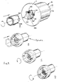
- FIG. 1 shows the various components of the double action pawl latch of the example in exploded view, with the exception of the securing nut.
- the latch 1 comprises a front tubular latch body 10 which has an enlarged head or bezel 11 which, in use, engages around the sides of an aperture at which the latch is fastened in a door, panel or the like which is to be secured using the latch 1.
- the front tubular latch body 10 has four screw-threaded portions 12 equally spaced around its circumference, separated by flats 13.
- a pair of deformable detents 14 are provided on opposite sides (one only shown in figure 1) and a locating slot 15 is provided at the rear end of the front latch body 10.
- a washer 16 is inserted over the front latch body 10 to engage the rear of the door, panel or the like and a screw-threaded nut is used to back-up the washer in order to secure the latch body in place.
- a rear tubular latch body 20 which, on assembly, mates with and is secured to the front tubular latch body 10 provides a tubular housing for securing the working components of the latch.
- the rear tubular latch body 20 has a barrel 21 with a pair of opposed apertures 22 into which the detents 14 are deformed to secure the rear latch body inside the front latch body.
- the barrel 21 may be partially splined about an annular portion 23 to provide an press fit within the front tubular latch body 10.
- a pair of diametrically opposed cross pin access slots 24 are provided in the annular portion 23 as is a location protrusion 25 which in use mates with the location slot 15.
- the rear tubular latch body 20 incorporates an enlarged diameter portion 26 which has a diameter similar to that of the front tubular latch portion 10 and a pawl control section 27 which is again of slightly increased diameter.
- the pawl control section 27 has a part-annular protrusion 28 which provides a pair of abutments 29, 30 to limit rotation of the pawl 40 to approximately 90° when it is axially aligned with the protrusion 28, and a further abutment 31 is provided which, in combination with the abutment 30, substantially completely prevents rotation of the pawl 40 when it is axially aligned with the abutment 31, as will be described below.
- An actuating spindle 50 which comprises a cylindrical spigot 51, has an enlarged front end portion 52 which includes a pair of annular ribs 53 to receive a synthetic rubber O-ring 54 and also provides plural part-annular abutment segments 55 separated by radial key slots 56.
- the front end portion 52 also includes a central axial protrusion 57.
- a spring washer 58 is disposed on the spigot 51 against the annular flange 53 and in use engages against the corresponding end of the barrel 21 of the rear tubular latch body 20.
- the spigot 51 includes a cross bore 58 for receipt of a cross pin 59.
- a pawl operating spindle 60 in the form of a hollow sleeve 61 has a pair of helical cam slots 62 which are diametrically opposed and has an enlarged diameter rear end portion 63 on which the pawl 40 is non-rotatably secured in use by means of a bolt 90 secured through a threaded counter bore 64 which is formed in a non-circular end protrusion 65 which extends, in use, through a similarly shaped aperture 41 in the pawl 40.
- the pawl 40 includes a pair of abutments 42, 43, which in use engage, respectively, with the abutment 30 and the abutment 29 or 31 of the rear tubular latch portion 20.
- the actuating spindle 50 carrying the spring washer 57, is inserted in the front end of the rear tubular latch body 20 and the pawl operating spindle 60 is inserted from the opposite end, a helical spring 70 being disposed within the pawl operating spindle 60 between the two to bias them apart.
- the cross pin 59 is then inserted, through one of the cross pin access apertures 24, through the helical cam slots 62 of the pawl operating spindle 60 and the bore 58 of the actuating spindle 50.
- the two spindles are thus secured together within the rear tubular latch body 20 and are free to rotate within it.
- the rear tubular latch body is then presented to the front tubular latch body with the locating protrusion 25 aligned with the location slot 15 and it is press-fitted into the front tubular latch body 10, capturing the actuating spindle 50 between the two latch bodies.
- the detents 14 are then deformed inwardly into engagement with the apertures 22 to secure the rear tubular latch body within the front tubular latch body 10.
- the assembled latch body may then be presented from the front through an aperture to which it is to be secured, the washer 16 inserted over the rear tubular latch body 20 and onto the front tubular latch body 10 and the securing nut 80 similarly positioned and tightened up on the screw threaded portions 12 to fix the latch in position.
- the pawl 40 can then be attached to the pawl operating spindle 60 by means of the bolt 90.
- the latch After assembly the latch is in the unlocked or unlatched position with the pawl axially aligned with the abutments 29 and 30 and capable of rotation over a 90° angle defined by engagement of the abutment 42 with the abutment 30 and the abutment 43 with the abutment 29.
- the actuating spindle In order to operate the latch the actuating spindle is rotated by means of a key engaged through the head or bezel 11 with the front end portion 52 of the actuating spindle 50 so as to enable rotation of the pawl from a first angular position in which the abutment 43 engages the abutment 29 to a second angular position in which the abutment 42 engages the abutment 30 (i.e.
- the pawl actuating spindle being driven by means of its connection with the cross pin 59 from the actuating spindle 50.
- the abutment 42 engages the abutment 30 the pawl actuating spindle can no longer rotate and thereafter continued rotation of the actuating spindle 50 causes the cross pin 59 to move along the cam slots 52 drawing the pawl actuating spindle 60 against the biasing action of the spring 70 further around the spigot 51 of the actuating spindle 50, carrying the pawl 40 with it.
- Rotation of the pawl is substantially completely prevented by continued engagement of the abutments 42 and 30 and also by the abutments 43 and 31.
- the cross pin 59 reaches the ends of the cam slots 62 which have a detent 66, the latch is fully locked or latched in a position drawn-up towards the front of the latch, against the frame or surround on which the door or panel is secured.
- the front tubular latch body 10 has an internally thickened wall portion 17 which provides a pair of axially extending abutments 18,19. These are capable of engagement with abutments 81, 82 which are provided on respective protrusions 83, 84 on adjacent ones of the part-annular portions 55 of the head 52 of the actuating spindle 50.
- Figures 2A-2C show a front view of the latch with the head or bezel 11 removed and with internal components in cross-section, in respective latched, 90° rotated from latched, and 180° fully unlatched positions and Figures 2D-2F show a rear view of the latch in corresponding positions. It can be seen how, in the latched position, in which the abutment 42 on the pawl 40 is engaged with the abutment 30 on the protrusion 28, the abutment 82 on the actuating spindle 50 is engaged with the abutment 19 on the front tubular latch body 10, in Figures 2A and 2D.
- Figures 2B and 2E illustrate the 90° from latched position with the abutment 42 riding against the abutment 30 during unlatching and with the actuating spindle 90° rotated from the latch position.
- Figures 2C and 2F illustrate the fully unlatched position in which the abutment 43 on the spindle 40 is engaged with the abutment 29 on the protrusion 28 and the abutment 18 on the actuating spindle 50 is engaged with the abutment 81 upon the front tubular latch body 10.
- loadings on the latch can be shared between the respective pairs of abutments, to reduce overall loadings on the rear tubular latch body protrusion 28 and the pawl 40.
- Figures 2A-2F also show the securing nut 80 and figures 2D-2F show the bolt 90 which secures the pawl 40 to the pawl operating spindle 60.
- Figures 2A-2C also show, in cross-section, the central protrusion 57 which can be seen to be non-circular.
- FIGS 3A-3B and 4A-4D illustrate a further aspect of the latch.
- the bezel or head 11 of the front tubular latch body 10 has a front aperture 100 which has radially outwardly extending key slots 101 which mate with corresponding radial protrusions 202 on the end of a tubular key 200.
- the central protrusion 57 has been removed from the figures.
- the position of the part-annular protrusions 55 and the radial key slots 56 in the actuating spindle 50 can be clearly seen.
- the latch is shown in the latched position and it can be seen that the key slots 101 are not aligned with the key slots 56. This means that the key 200 can only be inserted until the ends of the key protrusions 202 engage against the front surfaces 55' of the protrusions or abutments 55.
- a part annular rearwardly extending abutment 102 within the head or bezel 11 prevents withdrawal of the key by engaging the rear ends (in the sense of the key rather than the latch) of the key protrusions 202.
Landscapes
- Engineering & Computer Science (AREA)
- Mechanical Engineering (AREA)
- Lock And Its Accessories (AREA)
Priority Applications (2)
| Application Number | Priority Date | Filing Date | Title |
|---|---|---|---|
| DE1997622617 DE69722617T2 (de) | 1997-09-24 | 1997-09-24 | Doppelwirkende Sperrklinke |
| EP19970307462 EP0905339B1 (de) | 1997-09-24 | 1997-09-24 | Doppelwirkende Sperrklinke |
Applications Claiming Priority (1)
| Application Number | Priority Date | Filing Date | Title |
|---|---|---|---|
| EP19970307462 EP0905339B1 (de) | 1997-09-24 | 1997-09-24 | Doppelwirkende Sperrklinke |
Publications (2)
| Publication Number | Publication Date |
|---|---|
| EP0905339A1 true EP0905339A1 (de) | 1999-03-31 |
| EP0905339B1 EP0905339B1 (de) | 2003-06-04 |
Family
ID=8229521
Family Applications (1)
| Application Number | Title | Priority Date | Filing Date |
|---|---|---|---|
| EP19970307462 Expired - Lifetime EP0905339B1 (de) | 1997-09-24 | 1997-09-24 | Doppelwirkende Sperrklinke |
Country Status (2)
| Country | Link |
|---|---|
| EP (1) | EP0905339B1 (de) |
| DE (1) | DE69722617T2 (de) |
Cited By (3)
| Publication number | Priority date | Publication date | Assignee | Title |
|---|---|---|---|---|
| WO2008138416A1 (de) * | 2007-05-16 | 2008-11-20 | Dirak Dieter Ramsauer Konstruktionselemente Gmbh & Co. Kg | Kompressionsverschluss |
| WO2012113387A3 (de) * | 2011-02-23 | 2012-12-20 | Krauss-Maffei Wegmann Gmbh & Co. Kg | Vorrichtung zum verriegeln zweier bauelemente und brückenverlegefahrzeug mit einer verriegelungsvorrichtung |
| US20140271027A1 (en) * | 2013-03-15 | 2014-09-18 | Ron R. Daniels | Lock Device and Method of Use |
Families Citing this family (1)
| Publication number | Priority date | Publication date | Assignee | Title |
|---|---|---|---|---|
| DE202005011092U1 (de) * | 2005-07-14 | 2006-09-07 | Otto Ganter Gmbh & Co. Kg Normteilefabrik | Rastriegel mit mittels Drehbewegung axial antreibbarem Raststift |
Citations (6)
| Publication number | Priority date | Publication date | Assignee | Title |
|---|---|---|---|---|
| US2269264A (en) | 1941-03-04 | 1942-01-06 | Haim Albert | Swing lock fastener |
| US2860904A (en) | 1955-06-07 | 1958-11-18 | South Chester Corp | Door or panel fastener |
| US3402958A (en) | 1967-03-28 | 1968-09-24 | Southco | Door or panel fastener |
| GB2158866A (en) * | 1984-05-16 | 1985-11-20 | Southco | Latch mechanism having pull- in action |
| US4671547A (en) * | 1985-07-31 | 1987-06-09 | The Eastern Company | Half turn cabinet latch with door gasket clamping capability |
| GB2172648B (en) | 1985-03-22 | 1988-06-08 | Southco | Key and latch-actuator |
-
1997
- 1997-09-24 EP EP19970307462 patent/EP0905339B1/de not_active Expired - Lifetime
- 1997-09-24 DE DE1997622617 patent/DE69722617T2/de not_active Expired - Lifetime
Patent Citations (7)
| Publication number | Priority date | Publication date | Assignee | Title |
|---|---|---|---|---|
| US2269264A (en) | 1941-03-04 | 1942-01-06 | Haim Albert | Swing lock fastener |
| US2860904A (en) | 1955-06-07 | 1958-11-18 | South Chester Corp | Door or panel fastener |
| US3402958A (en) | 1967-03-28 | 1968-09-24 | Southco | Door or panel fastener |
| GB2158866A (en) * | 1984-05-16 | 1985-11-20 | Southco | Latch mechanism having pull- in action |
| GB2158866B (en) | 1984-05-16 | 1986-07-09 | Southco | Latch mechanism having pull-up action |
| GB2172648B (en) | 1985-03-22 | 1988-06-08 | Southco | Key and latch-actuator |
| US4671547A (en) * | 1985-07-31 | 1987-06-09 | The Eastern Company | Half turn cabinet latch with door gasket clamping capability |
Cited By (4)
| Publication number | Priority date | Publication date | Assignee | Title |
|---|---|---|---|---|
| WO2008138416A1 (de) * | 2007-05-16 | 2008-11-20 | Dirak Dieter Ramsauer Konstruktionselemente Gmbh & Co. Kg | Kompressionsverschluss |
| WO2012113387A3 (de) * | 2011-02-23 | 2012-12-20 | Krauss-Maffei Wegmann Gmbh & Co. Kg | Vorrichtung zum verriegeln zweier bauelemente und brückenverlegefahrzeug mit einer verriegelungsvorrichtung |
| EP3228749A1 (de) * | 2011-02-23 | 2017-10-11 | Krauss-Maffei Wegmann GmbH & Co. KG | Vorrichtung zum verriegeln zweier bauelemente und brückenverlegefahrzeug mit einer verriegelungsvorrichtung |
| US20140271027A1 (en) * | 2013-03-15 | 2014-09-18 | Ron R. Daniels | Lock Device and Method of Use |
Also Published As
| Publication number | Publication date |
|---|---|
| DE69722617T2 (de) | 2003-12-18 |
| EP0905339B1 (de) | 2003-06-04 |
| DE69722617D1 (de) | 2003-07-10 |
Similar Documents
| Publication | Publication Date | Title |
|---|---|---|
| US6279360B1 (en) | Cylindrical lock with simpler positioning assembly | |
| CA2435341C (en) | High strength lever handle lock mechanism | |
| DE69417530T2 (de) | Gegen Einbruch widerstandsfähiges Zylinderschloss | |
| US6640592B2 (en) | Key operated latch with combined rotational and translational latching action | |
| US5761936A (en) | Cylindrical lever-type door lock | |
| US5617749A (en) | Door lock | |
| US5398531A (en) | Rotational housing assembly for a lock assembly with a removable core | |
| AU2002236783A1 (en) | High strength lever handle lock mechanism | |
| CA2530431A1 (en) | Freewheeling lock apparatus and method | |
| JPH02292475A (ja) | 施錠機構 | |
| US5351513A (en) | Double cylinder deadbolt | |
| US20040031300A1 (en) | Inside locking device of flat handle lock | |
| AU684509B2 (en) | Non-handed, concealed-screw lock mounting mechanism | |
| EP0905339B1 (de) | Doppelwirkende Sperrklinke | |
| EP0905340A1 (de) | Doppelwirkende Sperrklinke | |
| EP0905338A1 (de) | Doppelwirkende Sperrklinke | |
| EP1076142B1 (de) | Türschlossvorrichtung mit abnehmbarem Betätigungsgriff | |
| US5551263A (en) | Lock with dead bolt camming action on 90 degree lock cylinder rotation | |
| US6408662B1 (en) | Locking device with key-operated lock | |
| EP1073815B1 (de) | Durch einen schlüssel betätigtes schloss mit kombinierter dreh- und schiebeschlissbewegung | |
| US20080083253A1 (en) | Door lock assembly with which a door cannot be unlatched by rotating a handle | |
| DE4120814A1 (de) | Anordnung eines kabelschlosses an einem zweiradrahmen | |
| GB2198178A (en) | Fastener | |
| JP2591708B2 (ja) | 錠前装置 | |
| EP0590330A1 (de) | Schliesszylinder |
Legal Events
| Date | Code | Title | Description |
|---|---|---|---|
| PUAI | Public reference made under article 153(3) epc to a published international application that has entered the european phase |
Free format text: ORIGINAL CODE: 0009012 |
|
| AK | Designated contracting states |
Kind code of ref document: A1 Designated state(s): DE ES FR GB IT NL SE |
|
| AX | Request for extension of the european patent |
Free format text: AL;LT;LV;RO;SI |
|
| 17P | Request for examination filed |
Effective date: 19990906 |
|
| AKX | Designation fees paid |
Free format text: DE ES FR GB IT NL SE |
|
| RAP1 | Party data changed (applicant data changed or rights of an application transferred) |
Owner name: MCKECHNIE SPECIALIST PRODUCTS LIMITED |
|
| 17Q | First examination report despatched |
Effective date: 20020206 |
|
| GRAH | Despatch of communication of intention to grant a patent |
Free format text: ORIGINAL CODE: EPIDOS IGRA |
|
| RAP1 | Party data changed (applicant data changed or rights of an application transferred) |
Owner name: MCKECHNIE SPECIALIST PRODUCTS LIMITED |
|
| GRAH | Despatch of communication of intention to grant a patent |
Free format text: ORIGINAL CODE: EPIDOS IGRA |
|
| GRAA | (expected) grant |
Free format text: ORIGINAL CODE: 0009210 |
|
| AK | Designated contracting states |
Designated state(s): DE ES FR GB IT NL SE |
|
| PG25 | Lapsed in a contracting state [announced via postgrant information from national office to epo] |
Ref country code: NL Free format text: LAPSE BECAUSE OF FAILURE TO SUBMIT A TRANSLATION OF THE DESCRIPTION OR TO PAY THE FEE WITHIN THE PRESCRIBED TIME-LIMIT Effective date: 20030604 Ref country code: IT Free format text: LAPSE BECAUSE OF FAILURE TO SUBMIT A TRANSLATION OF THE DESCRIPTION OR TO PAY THE FEE WITHIN THE PRE;WARNING: LAPSES OF ITALIAN PATENTS WITH EFFECTIVE DATE BEFORE 2007 MAY HAVE OCCURRED AT ANY TIME BEFORE 2007. THE CORRECT EFFECTIVE DATE MAY BE DIFFERENT FROM THE ONE RECORDED.SCRIBED TIME-LIMIT Effective date: 20030604 |
|
| REG | Reference to a national code |
Ref country code: GB Ref legal event code: FG4D |
|
| REF | Corresponds to: |
Ref document number: 69722617 Country of ref document: DE Date of ref document: 20030710 Kind code of ref document: P |
|
| REG | Reference to a national code |
Ref country code: SE Ref legal event code: TRGR |
|
| PG25 | Lapsed in a contracting state [announced via postgrant information from national office to epo] |
Ref country code: ES Free format text: LAPSE BECAUSE OF FAILURE TO SUBMIT A TRANSLATION OF THE DESCRIPTION OR TO PAY THE FEE WITHIN THE PRESCRIBED TIME-LIMIT Effective date: 20030915 |
|
| NLV1 | Nl: lapsed or annulled due to failure to fulfill the requirements of art. 29p and 29m of the patents act | ||
| ET | Fr: translation filed | ||
| PLBE | No opposition filed within time limit |
Free format text: ORIGINAL CODE: 0009261 |
|
| STAA | Information on the status of an ep patent application or granted ep patent |
Free format text: STATUS: NO OPPOSITION FILED WITHIN TIME LIMIT |
|
| 26N | No opposition filed |
Effective date: 20040305 |
|
| PGFP | Annual fee paid to national office [announced via postgrant information from national office to epo] |
Ref country code: FR Payment date: 20041026 Year of fee payment: 8 |
|
| PG25 | Lapsed in a contracting state [announced via postgrant information from national office to epo] |
Ref country code: FR Free format text: LAPSE BECAUSE OF NON-PAYMENT OF DUE FEES Effective date: 20060531 |
|
| REG | Reference to a national code |
Ref country code: FR Ref legal event code: ST Effective date: 20060531 |
|
| PGFP | Annual fee paid to national office [announced via postgrant information from national office to epo] |
Ref country code: GB Payment date: 20160921 Year of fee payment: 20 Ref country code: DE Payment date: 20160920 Year of fee payment: 20 |
|
| PGFP | Annual fee paid to national office [announced via postgrant information from national office to epo] |
Ref country code: SE Payment date: 20160914 Year of fee payment: 20 |
|
| REG | Reference to a national code |
Ref country code: DE Ref legal event code: R071 Ref document number: 69722617 Country of ref document: DE |
|
| REG | Reference to a national code |
Ref country code: GB Ref legal event code: PE20 Expiry date: 20170923 |
|
| REG | Reference to a national code |
Ref country code: SE Ref legal event code: EUG |
|
| PG25 | Lapsed in a contracting state [announced via postgrant information from national office to epo] |
Ref country code: GB Free format text: LAPSE BECAUSE OF EXPIRATION OF PROTECTION Effective date: 20170923 |