EP0905280A2 - Graded bond coat for a thermal barrier coating system - Google Patents
Graded bond coat for a thermal barrier coating system Download PDFInfo
- Publication number
- EP0905280A2 EP0905280A2 EP98306186A EP98306186A EP0905280A2 EP 0905280 A2 EP0905280 A2 EP 0905280A2 EP 98306186 A EP98306186 A EP 98306186A EP 98306186 A EP98306186 A EP 98306186A EP 0905280 A2 EP0905280 A2 EP 0905280A2
- Authority
- EP
- European Patent Office
- Prior art keywords
- bond coat
- thermal
- layer
- layers
- substrate
- Prior art date
- Legal status (The legal status is an assumption and is not a legal conclusion. Google has not performed a legal analysis and makes no representation as to the accuracy of the status listed.)
- Withdrawn
Links
Images

Classifications
-
- C—CHEMISTRY; METALLURGY
- C23—COATING METALLIC MATERIAL; COATING MATERIAL WITH METALLIC MATERIAL; CHEMICAL SURFACE TREATMENT; DIFFUSION TREATMENT OF METALLIC MATERIAL; COATING BY VACUUM EVAPORATION, BY SPUTTERING, BY ION IMPLANTATION OR BY CHEMICAL VAPOUR DEPOSITION, IN GENERAL; INHIBITING CORROSION OF METALLIC MATERIAL OR INCRUSTATION IN GENERAL
- C23C—COATING METALLIC MATERIAL; COATING MATERIAL WITH METALLIC MATERIAL; SURFACE TREATMENT OF METALLIC MATERIAL BY DIFFUSION INTO THE SURFACE, BY CHEMICAL CONVERSION OR SUBSTITUTION; COATING BY VACUUM EVAPORATION, BY SPUTTERING, BY ION IMPLANTATION OR BY CHEMICAL VAPOUR DEPOSITION, IN GENERAL
- C23C28/00—Coating for obtaining at least two superposed coatings either by methods not provided for in a single one of groups C23C2/00 - C23C26/00 or by combinations of methods provided for in subclasses C23C and C25C or C25D
- C23C28/30—Coatings combining at least one metallic layer and at least one inorganic non-metallic layer
- C23C28/32—Coatings combining at least one metallic layer and at least one inorganic non-metallic layer including at least one pure metallic layer
- C23C28/321—Coatings combining at least one metallic layer and at least one inorganic non-metallic layer including at least one pure metallic layer with at least one metal alloy layer
- C23C28/3215—Coatings combining at least one metallic layer and at least one inorganic non-metallic layer including at least one pure metallic layer with at least one metal alloy layer at least one MCrAlX layer
-
- C—CHEMISTRY; METALLURGY
- C23—COATING METALLIC MATERIAL; COATING MATERIAL WITH METALLIC MATERIAL; CHEMICAL SURFACE TREATMENT; DIFFUSION TREATMENT OF METALLIC MATERIAL; COATING BY VACUUM EVAPORATION, BY SPUTTERING, BY ION IMPLANTATION OR BY CHEMICAL VAPOUR DEPOSITION, IN GENERAL; INHIBITING CORROSION OF METALLIC MATERIAL OR INCRUSTATION IN GENERAL
- C23C—COATING METALLIC MATERIAL; COATING MATERIAL WITH METALLIC MATERIAL; SURFACE TREATMENT OF METALLIC MATERIAL BY DIFFUSION INTO THE SURFACE, BY CHEMICAL CONVERSION OR SUBSTITUTION; COATING BY VACUUM EVAPORATION, BY SPUTTERING, BY ION IMPLANTATION OR BY CHEMICAL VAPOUR DEPOSITION, IN GENERAL
- C23C28/00—Coating for obtaining at least two superposed coatings either by methods not provided for in a single one of groups C23C2/00 - C23C26/00 or by combinations of methods provided for in subclasses C23C and C25C or C25D
- C23C28/30—Coatings combining at least one metallic layer and at least one inorganic non-metallic layer
- C23C28/32—Coatings combining at least one metallic layer and at least one inorganic non-metallic layer including at least one pure metallic layer
- C23C28/324—Coatings combining at least one metallic layer and at least one inorganic non-metallic layer including at least one pure metallic layer with at least one metal matrix material layer comprising a mixture of at least two metals or metal phases or a metal-matrix material with hard embedded particles, e.g. WC-Me
-
- C—CHEMISTRY; METALLURGY
- C23—COATING METALLIC MATERIAL; COATING MATERIAL WITH METALLIC MATERIAL; CHEMICAL SURFACE TREATMENT; DIFFUSION TREATMENT OF METALLIC MATERIAL; COATING BY VACUUM EVAPORATION, BY SPUTTERING, BY ION IMPLANTATION OR BY CHEMICAL VAPOUR DEPOSITION, IN GENERAL; INHIBITING CORROSION OF METALLIC MATERIAL OR INCRUSTATION IN GENERAL
- C23C—COATING METALLIC MATERIAL; COATING MATERIAL WITH METALLIC MATERIAL; SURFACE TREATMENT OF METALLIC MATERIAL BY DIFFUSION INTO THE SURFACE, BY CHEMICAL CONVERSION OR SUBSTITUTION; COATING BY VACUUM EVAPORATION, BY SPUTTERING, BY ION IMPLANTATION OR BY CHEMICAL VAPOUR DEPOSITION, IN GENERAL
- C23C28/00—Coating for obtaining at least two superposed coatings either by methods not provided for in a single one of groups C23C2/00 - C23C26/00 or by combinations of methods provided for in subclasses C23C and C25C or C25D
- C23C28/30—Coatings combining at least one metallic layer and at least one inorganic non-metallic layer
- C23C28/32—Coatings combining at least one metallic layer and at least one inorganic non-metallic layer including at least one pure metallic layer
- C23C28/325—Coatings combining at least one metallic layer and at least one inorganic non-metallic layer including at least one pure metallic layer with layers graded in composition or in physical properties
-
- C—CHEMISTRY; METALLURGY
- C23—COATING METALLIC MATERIAL; COATING MATERIAL WITH METALLIC MATERIAL; CHEMICAL SURFACE TREATMENT; DIFFUSION TREATMENT OF METALLIC MATERIAL; COATING BY VACUUM EVAPORATION, BY SPUTTERING, BY ION IMPLANTATION OR BY CHEMICAL VAPOUR DEPOSITION, IN GENERAL; INHIBITING CORROSION OF METALLIC MATERIAL OR INCRUSTATION IN GENERAL
- C23C—COATING METALLIC MATERIAL; COATING MATERIAL WITH METALLIC MATERIAL; SURFACE TREATMENT OF METALLIC MATERIAL BY DIFFUSION INTO THE SURFACE, BY CHEMICAL CONVERSION OR SUBSTITUTION; COATING BY VACUUM EVAPORATION, BY SPUTTERING, BY ION IMPLANTATION OR BY CHEMICAL VAPOUR DEPOSITION, IN GENERAL
- C23C28/00—Coating for obtaining at least two superposed coatings either by methods not provided for in a single one of groups C23C2/00 - C23C26/00 or by combinations of methods provided for in subclasses C23C and C25C or C25D
- C23C28/30—Coatings combining at least one metallic layer and at least one inorganic non-metallic layer
- C23C28/34—Coatings combining at least one metallic layer and at least one inorganic non-metallic layer including at least one inorganic non-metallic material layer, e.g. metal carbide, nitride, boride, silicide layer and their mixtures, enamels, phosphates and sulphates
- C23C28/345—Coatings combining at least one metallic layer and at least one inorganic non-metallic layer including at least one inorganic non-metallic material layer, e.g. metal carbide, nitride, boride, silicide layer and their mixtures, enamels, phosphates and sulphates with at least one oxide layer
- C23C28/3455—Coatings combining at least one metallic layer and at least one inorganic non-metallic layer including at least one inorganic non-metallic material layer, e.g. metal carbide, nitride, boride, silicide layer and their mixtures, enamels, phosphates and sulphates with at least one oxide layer with a refractory ceramic layer, e.g. refractory metal oxide, ZrO2, rare earth oxides or a thermal barrier system comprising at least one refractory oxide layer
-
- Y—GENERAL TAGGING OF NEW TECHNOLOGICAL DEVELOPMENTS; GENERAL TAGGING OF CROSS-SECTIONAL TECHNOLOGIES SPANNING OVER SEVERAL SECTIONS OF THE IPC; TECHNICAL SUBJECTS COVERED BY FORMER USPC CROSS-REFERENCE ART COLLECTIONS [XRACs] AND DIGESTS
- Y10—TECHNICAL SUBJECTS COVERED BY FORMER USPC
- Y10T—TECHNICAL SUBJECTS COVERED BY FORMER US CLASSIFICATION
- Y10T428/00—Stock material or miscellaneous articles
- Y10T428/12—All metal or with adjacent metals
- Y10T428/12458—All metal or with adjacent metals having composition, density, or hardness gradient
-
- Y—GENERAL TAGGING OF NEW TECHNOLOGICAL DEVELOPMENTS; GENERAL TAGGING OF CROSS-SECTIONAL TECHNOLOGIES SPANNING OVER SEVERAL SECTIONS OF THE IPC; TECHNICAL SUBJECTS COVERED BY FORMER USPC CROSS-REFERENCE ART COLLECTIONS [XRACs] AND DIGESTS
- Y10—TECHNICAL SUBJECTS COVERED BY FORMER USPC
- Y10T—TECHNICAL SUBJECTS COVERED BY FORMER US CLASSIFICATION
- Y10T428/00—Stock material or miscellaneous articles
- Y10T428/12—All metal or with adjacent metals
- Y10T428/12493—Composite; i.e., plural, adjacent, spatially distinct metal components [e.g., layers, joint, etc.]
- Y10T428/12535—Composite; i.e., plural, adjacent, spatially distinct metal components [e.g., layers, joint, etc.] with additional, spatially distinct nonmetal component
- Y10T428/12542—More than one such component
- Y10T428/12549—Adjacent to each other
-
- Y—GENERAL TAGGING OF NEW TECHNOLOGICAL DEVELOPMENTS; GENERAL TAGGING OF CROSS-SECTIONAL TECHNOLOGIES SPANNING OVER SEVERAL SECTIONS OF THE IPC; TECHNICAL SUBJECTS COVERED BY FORMER USPC CROSS-REFERENCE ART COLLECTIONS [XRACs] AND DIGESTS
- Y10—TECHNICAL SUBJECTS COVERED BY FORMER USPC
- Y10T—TECHNICAL SUBJECTS COVERED BY FORMER US CLASSIFICATION
- Y10T428/00—Stock material or miscellaneous articles
- Y10T428/12—All metal or with adjacent metals
- Y10T428/12493—Composite; i.e., plural, adjacent, spatially distinct metal components [e.g., layers, joint, etc.]
- Y10T428/12535—Composite; i.e., plural, adjacent, spatially distinct metal components [e.g., layers, joint, etc.] with additional, spatially distinct nonmetal component
- Y10T428/12576—Boride, carbide or nitride component
-
- Y—GENERAL TAGGING OF NEW TECHNOLOGICAL DEVELOPMENTS; GENERAL TAGGING OF CROSS-SECTIONAL TECHNOLOGIES SPANNING OVER SEVERAL SECTIONS OF THE IPC; TECHNICAL SUBJECTS COVERED BY FORMER USPC CROSS-REFERENCE ART COLLECTIONS [XRACs] AND DIGESTS
- Y10—TECHNICAL SUBJECTS COVERED BY FORMER USPC
- Y10T—TECHNICAL SUBJECTS COVERED BY FORMER US CLASSIFICATION
- Y10T428/00—Stock material or miscellaneous articles
- Y10T428/12—All metal or with adjacent metals
- Y10T428/12493—Composite; i.e., plural, adjacent, spatially distinct metal components [e.g., layers, joint, etc.]
- Y10T428/12535—Composite; i.e., plural, adjacent, spatially distinct metal components [e.g., layers, joint, etc.] with additional, spatially distinct nonmetal component
- Y10T428/12611—Oxide-containing component
- Y10T428/12618—Plural oxides
-
- Y—GENERAL TAGGING OF NEW TECHNOLOGICAL DEVELOPMENTS; GENERAL TAGGING OF CROSS-SECTIONAL TECHNOLOGIES SPANNING OVER SEVERAL SECTIONS OF THE IPC; TECHNICAL SUBJECTS COVERED BY FORMER USPC CROSS-REFERENCE ART COLLECTIONS [XRACs] AND DIGESTS
- Y10—TECHNICAL SUBJECTS COVERED BY FORMER USPC
- Y10T—TECHNICAL SUBJECTS COVERED BY FORMER US CLASSIFICATION
- Y10T428/00—Stock material or miscellaneous articles
- Y10T428/12—All metal or with adjacent metals
- Y10T428/12493—Composite; i.e., plural, adjacent, spatially distinct metal components [e.g., layers, joint, etc.]
- Y10T428/12771—Transition metal-base component
- Y10T428/12806—Refractory [Group IVB, VB, or VIB] metal-base component
- Y10T428/12826—Group VIB metal-base component
- Y10T428/12847—Cr-base component
- Y10T428/12854—Next to Co-, Fe-, or Ni-base component
-
- Y—GENERAL TAGGING OF NEW TECHNOLOGICAL DEVELOPMENTS; GENERAL TAGGING OF CROSS-SECTIONAL TECHNOLOGIES SPANNING OVER SEVERAL SECTIONS OF THE IPC; TECHNICAL SUBJECTS COVERED BY FORMER USPC CROSS-REFERENCE ART COLLECTIONS [XRACs] AND DIGESTS
- Y10—TECHNICAL SUBJECTS COVERED BY FORMER USPC
- Y10T—TECHNICAL SUBJECTS COVERED BY FORMER US CLASSIFICATION
- Y10T428/00—Stock material or miscellaneous articles
- Y10T428/12—All metal or with adjacent metals
- Y10T428/12493—Composite; i.e., plural, adjacent, spatially distinct metal components [e.g., layers, joint, etc.]
- Y10T428/12771—Transition metal-base component
- Y10T428/12861—Group VIII or IB metal-base component
- Y10T428/12931—Co-, Fe-, or Ni-base components, alternative to each other
Definitions
- the present invention relates to protective coatings for components exposed to high temperatures, such as components of a gas turbine engine. More particularly, this invention is directed to a thermal barrier coating system that incorporates a graded bond coat whose thermal conductivity and thermal expansion properties are tailored to promote spall resistance of the coating system.
- the operating environment within a gas turbine engine is both thermally and chemically hostile.
- Significant advances in high temperature alloys have been achieved through the formulation of iron, nickel and cobalt-base superalloys, though components formed from such alloys often cannot withstand long service exposures if located in certain sections of a gas turbine engine, such as the turbine, combustor or augmentor.
- a common solution is to protect the surfaces of such components with an environmental coating system, such as an aluminide coating or a thermal barrier coating system (TBC).
- TBC thermal barrier coating system
- the latter includes an environmentally-resistant bond coat and a layer of thermal-insulating ceramic applied over the bond coat.
- Bond coats are typically formed from an oxidation-resistant alloy such as MCrAIY where M is iron, cobalt and/or nickel, or from a diffusion aluminide or platinum aluminide that forms an oxidation-resistant intermetallic.
- Metal oxides such as zirconia (ZrO 2 ) that is partially or fully stabilized by yttria (Y 2 O 3 ), magnesia (MgO) or another oxide, have been widely employed as the material for the thermal-insulating ceramic layer.
- the ceramic layer is typically deposited by air plasma spraying (APS), low pressure plasma spraying (LPPS), or a physical vapor deposition (PVD) technique, such as electron beam physical vapor deposition (EBPVD) which yields a strain-tolerant columnar grain structure.
- APS air plasma spraying
- LPPS low pressure plasma spraying
- PVD physical vapor deposition
- EBPVD electron beam physical vapor deposition
- Bond coats formed with the above-noted compositions protect the underlying superalloy substrate by forming an oxidation barrier for the underlying superalloy substrate.
- the aluminum content of these bond coat materials provides for the slow growth of a strong adherent continuous aluminum oxide layer (alumina scale) at elevated temperatures.
- This thermally grown oxide (TGO) protects the bond coat from oxidation and hot corrosion, and chemically bonds the ceramic layer to the bond coat.
- bond coat materials are particularly alloyed to be oxidation-resistant, the oxidation that occurs over time at elevated temperatures gradually depletes aluminum from the bond coat. Eventually, the level of aluminum within the bond coat is sufficiently depleted to prevent further slow growth of the protective oxide, and to allow for the more rapid growth of nonprotective oxides. At such time, spallation may occur at the interface between the bond coat and the aluminum oxide layer or the interface between the oxide layer and the ceramic layer. Even without the formation of nonprotective oxides, spallation may occur due to stress generation.
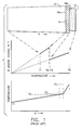
- a thermal barrier coating system is shown as comprising a ceramic layer 12 adhered to a substrate 10 by a bond coat 14.
- the coefficients of thermal expansion (CTE or ⁇ ) of the substrate 10 and metallic bond coat 14 are roughly equal, as are their coefficients of thermal conductivity (k).
- the CTE and thermal conductivity of the ceramic layer 12 are considerably less than that of the substrate 10 and bond coat 14.
- the CTEs of ceramic materials used to form the ceramic layer 12 are generally on the order of about 50%-60% of that of the materials for the substrate 10 and bond coat 14.
- the CTE of the protective oxide layer is even lower than that of the ceramic layer 12. Consequently, and as represented in FIGURE 1, while little relative expansion occurs at the interface 16a between the substrate 10 and bond coat 14 at elevated temperatures, a considerable difference in expansion occurs at the interface 16b between the bond coat 14 and ceramic layer 12. This difference in expansion generates considerable shear forces that promote spallation of the ceramic layer 12.
- the maximum service temperatures of the substrate 10 (T 2 ), bond coat 14 (T 3 ) and the ceramic layer 12 (T 4 ) also differ from each other due to their differences in thermal conductivity.
- the temperature T 4 at the outer surface of the ceramic layer 12 is considerably higher than the temperature T 3 at the interface 16b between the ceramic layer 12 and bond coat 14.
- the lower service temperature of the bond coat 14 reduces its rate of oxidation, and therefore promotes the overall service life of the coating system.
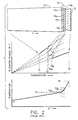
- FIGURE 2 shows a bond coat 14 composed of inner and outer layers 14a and 14b.
- the conventional practice has been to formulate the inner and outer layers 14a and 14b to have CTEs between that of the substrate 10 and ceramic layer 12, with the CTE of the inner layer 14a being closer to that of the substrate 10 and the CTE of the outer layer 14b being closer to that of the ceramic layer 12.
- the inner layer 14a may have a composition of about two parts bond coat alloy and one part metal oxide
- the outer layer 14b would have a composition of about one part bond coat alloy and two parts metal oxide.
- the resulting advantageous "graded" effect on thermal expansion is schematically and graphically represented in FIGURE 2.
- the bond coat layers 14a and 14b have lower coefficients of thermal conductivity as compared to the bond coat 14 of FIGURE 1 due to their inclusion of metal oxides, whose coefficients of thermal conductivity are considerably lower than that of metallic bond coat alloys. Because the bond coat layers 14a and 14b cannot conduct heat as readily to the substrate 10, the service temperature of the bond coat 14 is higher, as shown by the indicated temperatures T 3a and T 3b for the interfaces 16b and 16c between the inner and outer bond coat layers 14a and 14b, and between the outer layer 14b and the ceramic layer 12, respectively.
- the higher service temperature of the bond coat 14 (often on the order of about a 10°C difference) leads to accelerated oxidation, thus shortening the service life of the coating system.
- an article comprising:
- an article comprising:
- the present invention provides a bond coat of a thermal barrier coating system (TBC) for components designed for use in a hostile thermal environment, such as turbine, combustor and augmentor components of a gas turbine engine.
- TBC thermal barrier coating system
- the composition of the bond coat has graded thermal expansion properties that moderate the transition between a metal substrate and a thermal insulating ceramic layer of a TBC protecting the substrate, while also reducing the service temperature of the bond coat so as to reduce its rate of oxidation. Consequently, the bond coat of this invention yields a thermal barrier coating system that is highly resistant to spallation.
- a thermal barrier coating system in accordance with this invention generally includes a bond coat adhering a thermal-insulating layer to a substrate.
- the substrate is preferably a material that exhibits high strength at elevated temperatures, such as a cobalt, nickel or iron-base superalloy, though it is foreseeable that other materials could be used.
- the thermal-insulating layer is preferably a ceramic material, as is also conventional in the art. Because the substrate is metallic and the thermal-insulating layer is ceramic, their coefficients of thermal expansion (CTE or ⁇ ) and conductivity (k) differ considerably.
- Adhering the ceramic layer to the substrate is a bond coat comprising at least two layers.
- the two layers can be two discrete layers of a multilayer bond coat, or more generally two regions, one relatively more inward than the other, of a continuously graded structure (which can be considered a multilayer bond coat having an infinite number of "layers").
- the terms "layer” and “layers” will be used but understood to apply to each of these bond coat structures.
- the compositions of the two layers differ in order to grade the thermal expansion properties between the substrate and ceramic layer.
- compositions of the bond coat layers are tailored to achieve the following relationships: ⁇ s > ⁇ b1 and ⁇ b2 ⁇ t ⁇ ⁇ b1 and ⁇ b2 , and k b1 and k b2 are much closer to k s than k t , where:
- each layer of the bond coat preferably includes a metallic constituent and at least one additional constituent.
- the metallic and additional constituents are chosen to have chemistries that maintain sufficient thermodynamic equilibrium in order to avoid substantial changes during high temperature service.
- suitable metallic constituents are those that contain aluminum and/or chromium for the purpose of forming adhesion-promoting alumina and/or chromia, respectively, at the interface between the bond coat and thermal-insulating layer.
- the one or more additional constituents are preferably materials characterized by a relatively high coefficient of thermal conductivity (k) and relatively low CTE ( ⁇ ), i.e., a coefficient of thermal conductivity closer to k s (the coefficient of thermal conductivity of the substrate) and a coefficient of thermal expansion closer to ⁇ t (the coefficient of thermal expansion of the thermal-insulating layer).
- Suitable materials that meet these criteria for the additional constituents include metallic phases such as Cr, metal carbides, and certain intermetallic compounds such as B2-structured aluminides and Cr 3 Si.
- the inward layer preferably contains by volume a greater amount of the metallic constituent than of the additional constituent(s), while the outward layer of the bond coat preferably contains by volume a greater amount of the additional constituent(s) than the metallic constituent.
- the coefficients of thermal conductivity of the bond coat layers are very close to that of the substrate (k s ), and preferably within about 80% of k s in order to promote heat transfer from the outward layer of the bond coat to the substrate, which serves as a heat sink.
- k b1 and k b2 are approximately equal to k s , such that the service temperature of the bond coat is very nearly equal to that of the surface of the substrate.
- the expansion of the TBC system is fully graded at elevated service temperatures.
- ⁇ s > ⁇ b1 > ⁇ b2 > ⁇ t the expansion of the TBC system is fully graded at elevated service temperatures.
- stresses generated at interfaces between layers of the TBC system can be relaxed at service temperatures encountered by the bond coat.
- grading the thermal expansion of the layers that form the TBC system a more spall-resistant TBC system is achieved.
- the conductivity and expansion properties of the individual bond coat layers can be varied independently through the use of different metallic and high-conductivity, low-expansion constituents, such that the stress distribution and temperature profile through the thermal barrier coating system can be developed nearly independently of each other.
- the present invention is generally applicable to metal components that are protected from a thermally and chemically hostile environment by a thermal barrier coating system.
- a thermal barrier coating system includes the high and low pressure turbine nozzles and blades, shrouds, combustor liners and augmentor hardware of gas turbine engines. While the advantages of this invention are particularly applicable to gas turbine engine components, the teachings of this invention are generally applicable to any component on which a thermal barrier may be used to thermally insulate the component from its environment.
- FIGURE 3 A partial cross-section of a gas turbine engine component having a thermal barrier coating system in accordance with this invention is represented in FIGURE 3.
- the coating system is shown as including a thermal-insulating layer 12 bonded to a substrate 10 with a multilayer bond coat 20.
- the substrate 10 may be formed of an iron, nickel or cobalt-base superalloy, though it is foreseeable that other high temperature materials could be used.
- the thermal-insulating layer 12 is preferably a ceramic material deposited by physical vapor deposition using techniques known in the art, e.g., EBPVD, to yield a strain-tolerant columnar grain structure.
- the ceramic material could be deposited by other known processes, such as air plasma spraying (APS) and low pressure plasma spraying (LPPS).
- a preferred ceramic material for the thermal-insulating layer 12 is an yttria-stabilized zirconia (YSZ), though other ceramic materials could be used, including yttria, partially stabilized zirconia, or zirconia stabilized by other oxides, such as magnesia (MgO), ceria (CeO 2 ) or scandia (Sc 2 O 3 ).
- the bond coat 20 must be oxidation-resistant so as to be capable of protecting the underlying substrate 10 from oxidation and to enable the thermal-insulating layer 12 to more tenaciously adhere to the substrate 10.
- an alumina (Al 2 O 3 ) scale (not shown) may be formed on the surface of the bond coat 20 by exposure to elevated temperatures. The scale provides a surface to which the thermal-insulating layer 12 more tenaciously adheres, and emulates the thermally-grown oxide that will form between the thermal-insulating layer 12 and the bond coat 20 during high temperature service.
- the bond coat 20 preferably contains alumina- and/or chromia-formers, i.e., aluminum, chromium and their alloys and intermetallics.
- alumina- and/or chromia-formers i.e., aluminum, chromium and their alloys and intermetallics.
- Known bond coat materials include diffusion aluminides and MCrAIY, where M is iron, cobalt and/or nickel.
- FIGURE 3 shows the bond coat 20 of this invention as being composed of two discrete layers, an innermost layer 20a and an outermost layer 20b, though a greater number of bond coat layers can be employed.
- the bond coat 20 of FIGURE 3 could be continuously graded to have an infinite number of "layers," with the innermost and outermost layers 20a and 20b identifying relatively more inward and relatively more outward layers or regions, respectively, of the bond coat 20. Accordingly, bond coats having multiple discrete layers and those having continuously graded compositions are both within the scope of this invention.
- the innermost and outermost layers 20a and 20b have graded coefficients of thermal expansion ( ⁇ ), yet have coefficients of thermal conductivity (k) that are nearly equal to that of the substrate 10.
- ⁇ coefficients of thermal expansion
- k coefficients of thermal conductivity
- the graph comparing "% LENGTH CHANGE IN Y" (expansion in a plane parallel to the surface of the TBC) with service temperature shows the effect of formulating the bond coat layers 20a and 20b to have coefficients of thermal expansion ( ⁇ b1 and ⁇ b2 , respectively) between that of the substrate 10 ( ⁇ s ) and thermal-insulating layer 12 ( ⁇ t ), such that ⁇ s > ⁇ b1 > ⁇ b2 > ⁇ t .
- the coefficients of thermal conductivity of the bond coat layers 20a and 20b are closer to that of the substrate 10 (k s ) than to the thermal-insulating layer 12 (k t ), and preferably within about 80% of k s .
- the effect of this relationship is evidenced by the linearity between temperatures "T 1 " and "T 3 " in the graph showing temperatures through the thickness "X" of the TBC system of FIGURE 3.
- T 3 the temperature at the interface 22c between the outermost bond coat layer 20b and the thermal-insulating layer 12
- T 2 the temperature at the interface 22a between the innermost bond coat layer 20a and the substrate 10.
- temperatures are in contrast to those of the prior art graded bond coat system illustrated in FIGURE 2, where the temperature (T 3b ) at the interface 16c (between the outermost bond coat layer 16b and the thermal-insulating layer 12) is significantly higher (about 10 C) than the temperature (T 3a ) at the interface 16b (between the inner and outermost layers 16a and 16b) and the temperature T 2 at the interface 16a (between the innermost bond coat layer 16a and the substrate 10).
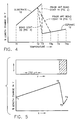
- FIGURE 4 The benefit of the improved thermal conductivity of the bond coat 20 is also illustrated in FIGURE 4, where "% LENGTH CHANGE IN Y" is shown relative to service temperatures for each of the TBC systems represented in FIGURES 1, 2 and 3.
- the multilayer bond coat 20 of this invention provides a graded transition in thermal expansion, as does the multilayer bond coat 14 of FIGURE 2, but with the added benefit that the maximum service temperature T 3 of the bond coat 20 is significantly less than the maximum service temperature T 3b of the multilayer bond coat 14 of FIGURE 2.
- the maximum service temperature T 4 for the thermal-insulating layer 12 of FIGURE 3 is also lower than the maximum service temperature T 4a of the thermal-insulating layer 12 of FIGURE 2.
- FIGURE 5 The effect on thermal expansion that a continuously graded bond coat in accordance with this invention has on a TBC system is illustrated in FIGURE 5, showing the graduated change in % length change in "Y" through the thickness "X” of the TBC system of FIGURE 3. While thermal expansion in the thermal-insulating layer 12 is considerably less than that in the substrate 10, the bond coat 20 of this invention provides a graded transition between the substrate 10 and thermal-insulating layer 12 across the modest service temperature extremes T 2 and T 3 of the bond coat 20.
- the benefits of this invention can be achieved with various compositional constituents for the bond coat layers 20a and 20b.
- the bond coat layers 20a and 20b preferably contain an oxidation-resistant metallic constituent and one or more additional constituents whose coefficients of thermal conductivity are near that of the metal substrate, yet whose CTEs is relatively close to that of ceramic.
- Aluminum- and/or chromium-containing compositions and intermetallics are suitable as the metallic constituent.
- Notable examples include diffusion aluminides (e.g., PtAl and NiAl), MCrAI (e.g., NiCrAl) and MCrAIY (e.g., NiCrAIY) in view of their proven reliability to resist oxidation and protect an underlying substrate.
- diffusion aluminides e.g., PtAl and NiAl
- MCrAI e.g., NiCrAl
- MCrAIY e.g., NiCrAIY
- metal oxide materials previously added to the bond coat 14 to form the prior art TBC of FIGURE 2 are unsuitable due to their low coefficients of thermal conductivity. Instead, the present invention relies on high-conductivity, low-expansion compositions that offer the ability to grade thermal expansion while retaining near-metal thermal conductivities.
- high-conductivity and low-expansion are used herein to be relative terms, where “high-conductivity” (“high-k”) refers to thermal conductivities on the order of the substrate material, and “low-expansion” (“low- ⁇ ”) refers to CTEs on the order of ceramic materials used for the thermal-insulating layer.
- While most preferred materials for this purpose are non-oxides, certain oxides such as BeO have sufficiently high thermal conductivity to be useful as a high-conductivity, low-expansion composition for this invention.
- Particularly suitable high-conductivity, low-expansion compositions include metallic phases such as ⁇ Cr, metal carbides including Cr 3 C 2 , SiC and WC, and certain intermetallic compounds such as B2-structured aluminides and Cr 3 Si.
- the individual layers of the bond coat 20 are formed to have different compositions to achieve the graded thermal expansion effect through the bond coat 20, whereby the bond coat layers have CTEs between that of the metal substrate and the thermal-insulating layer, with the CTE of the innermost layer (e.g., bond coat layer 20a) being closer to that of the metal substrate and the CTE of the outermost layer (e.g., bond coat layer 20b) being closer to that of the material for the thermal-insulating layer (e.g., a metal oxide).
- the innermost layer 20a can have a composition of about two parts metallic constituent and one part non-oxide constituent, while the outermost layer 20b contains about one part metallic constituent and two parts non-oxide constituent.
- An important and advantageous aspect of this invention is that the conductivity and expansion properties of the individual bond coat layers can be varied independently through the use of different metallic and high-conductivity, low-expansion constituents, such that the stress distribution and temperature profile through the thermal barrier coating system can be developed, and therefore optimally, nearly independently of each other.
Landscapes
- Chemical & Material Sciences (AREA)
- Inorganic Chemistry (AREA)
- Engineering & Computer Science (AREA)
- Chemical Kinetics & Catalysis (AREA)
- Materials Engineering (AREA)
- Mechanical Engineering (AREA)
- Metallurgy (AREA)
- Organic Chemistry (AREA)
- Ceramic Engineering (AREA)
- Other Surface Treatments For Metallic Materials (AREA)
- Coating By Spraying Or Casting (AREA)
- Physical Vapour Deposition (AREA)
Abstract
Description
- The present invention relates to protective coatings for components exposed to high temperatures, such as components of a gas turbine engine. More particularly, this invention is directed to a thermal barrier coating system that incorporates a graded bond coat whose thermal conductivity and thermal expansion properties are tailored to promote spall resistance of the coating system.
- The operating environment within a gas turbine engine is both thermally and chemically hostile. Significant advances in high temperature alloys have been achieved through the formulation of iron, nickel and cobalt-base superalloys, though components formed from such alloys often cannot withstand long service exposures if located in certain sections of a gas turbine engine, such as the turbine, combustor or augmentor. A common solution is to protect the surfaces of such components with an environmental coating system, such as an aluminide coating or a thermal barrier coating system (TBC). The latter includes an environmentally-resistant bond coat and a layer of thermal-insulating ceramic applied over the bond coat. Bond coats are typically formed from an oxidation-resistant alloy such as MCrAIY where M is iron, cobalt and/or nickel, or from a diffusion aluminide or platinum aluminide that forms an oxidation-resistant intermetallic. Metal oxides, such as zirconia (ZrO2) that is partially or fully stabilized by yttria (Y2O3), magnesia (MgO) or another oxide, have been widely employed as the material for the thermal-insulating ceramic layer. The ceramic layer is typically deposited by air plasma spraying (APS), low pressure plasma spraying (LPPS), or a physical vapor deposition (PVD) technique, such as electron beam physical vapor deposition (EBPVD) which yields a strain-tolerant columnar grain structure.
- Bond coats formed with the above-noted compositions protect the underlying superalloy substrate by forming an oxidation barrier for the underlying superalloy substrate. The aluminum content of these bond coat materials provides for the slow growth of a strong adherent continuous aluminum oxide layer (alumina scale) at elevated temperatures. This thermally grown oxide (TGO) protects the bond coat from oxidation and hot corrosion, and chemically bonds the ceramic layer to the bond coat. Though bond coat materials are particularly alloyed to be oxidation-resistant, the oxidation that occurs over time at elevated temperatures gradually depletes aluminum from the bond coat. Eventually, the level of aluminum within the bond coat is sufficiently depleted to prevent further slow growth of the protective oxide, and to allow for the more rapid growth of nonprotective oxides. At such time, spallation may occur at the interface between the bond coat and the aluminum oxide layer or the interface between the oxide layer and the ceramic layer. Even without the formation of nonprotective oxides, spallation may occur due to stress generation.
- Spallation of the ceramic layer is often triggered by the differences in coefficients of thermal expansion of the superalloy substrate, metallic bond coat and ceramic layer, including the thermally-grown aluminum oxide layer. As represented in FIGURE 1, a thermal barrier coating system is shown as comprising a
ceramic layer 12 adhered to asubstrate 10 by abond coat 14. The coefficients of thermal expansion (CTE or α) of thesubstrate 10 andmetallic bond coat 14 are roughly equal, as are their coefficients of thermal conductivity (k). However, the CTE and thermal conductivity of theceramic layer 12 are considerably less than that of thesubstrate 10 andbond coat 14. For example, the CTEs of ceramic materials used to form theceramic layer 12 are generally on the order of about 50%-60% of that of the materials for thesubstrate 10 andbond coat 14. The CTE of the protective oxide layer is even lower than that of theceramic layer 12. Consequently, and as represented in FIGURE 1, while little relative expansion occurs at theinterface 16a between thesubstrate 10 andbond coat 14 at elevated temperatures, a considerable difference in expansion occurs at theinterface 16b between thebond coat 14 andceramic layer 12. This difference in expansion generates considerable shear forces that promote spallation of theceramic layer 12. - As is evident from FIGURE 1, the maximum service temperatures of the substrate 10 (T2), bond coat 14 (T3) and the ceramic layer 12 (T4) also differ from each other due to their differences in thermal conductivity. Notably, the temperature T4 at the outer surface of the
ceramic layer 12 is considerably higher than the temperature T3 at theinterface 16b between theceramic layer 12 andbond coat 14. The lower service temperature of thebond coat 14 reduces its rate of oxidation, and therefore promotes the overall service life of the coating system. - To reduce the difference in thermal expansion between the ceramic layer and bond coat of a thermal barrier coating system, graded bond coats have been proposed in the prior art. An example of such a coating system is represented in FIGURE 2, which shows a
bond coat 14 composed of inner andouter layers 14a and 14b. The conventional practice has been to formulate the inner andouter layers 14a and 14b to have CTEs between that of thesubstrate 10 andceramic layer 12, with the CTE of the inner layer 14a being closer to that of thesubstrate 10 and the CTE of theouter layer 14b being closer to that of theceramic layer 12. For example, the inner layer 14a may have a composition of about two parts bond coat alloy and one part metal oxide, while theouter layer 14b would have a composition of about one part bond coat alloy and two parts metal oxide. The resulting advantageous "graded" effect on thermal expansion is schematically and graphically represented in FIGURE 2. - Also shown in FIGURE 2 is the effect that the graded bond coat composition has on service temperature. Notably, the
bond coat layers 14a and 14b have lower coefficients of thermal conductivity as compared to thebond coat 14 of FIGURE 1 due to their inclusion of metal oxides, whose coefficients of thermal conductivity are considerably lower than that of metallic bond coat alloys. Because thebond coat layers 14a and 14b cannot conduct heat as readily to thesubstrate 10, the service temperature of thebond coat 14 is higher, as shown by the indicated temperatures T3a and T3b for theinterfaces bond coat layers 14a and 14b, and between theouter layer 14b and theceramic layer 12, respectively. Accordingly, while the graded bond coat composition of FIGURE 2 reduces dissimilarities in thermal expansion, the higher service temperature of the bond coat 14 (often on the order of about a 10°C difference) leads to accelerated oxidation, thus shortening the service life of the coating system. - In view of the above, it can be seen that, while graded bond coat compositions of the past promote the service life of a thermal barrier coating system in one respect, the resulting increase in oxidation rate of the bond coat has a converse effect. Furthermore, the combination of metal and ceramic in graded bond coats produces a bond coat of limited ductility and toughness at the service temperatures encountered in a gas turbine engine. Accordingly, what is needed is a bond coat that yields a gradation of thermal expansion between the substrate and ceramic layer of a thermal barrier coating, without raising the service temperature of the bond coat. Such a bond coat would also preferably exhibit ductile behavior over a large portion of its service temperature range to allow for stress relaxation.
- According to a first aspect of the invention, there is provided an article comprising:
- a substrate having a coefficient of thermal expansion α s , and a coefficient of thermal conductivity ks;
- a bond coat comprising first and second layers, the first and second layers having coefficients of thermal expansion αb1 and α b2 respectively, and having coefficients of thermal conductivity kb1 and kb2, respectively; and
- a thermal-insulating layer on the bond coat, the thermal insulating layer having a coefficient of thermal expansion αt and a coefficient of thermal conductivity kt;
- wherein αs > αb1, and αb2, α t < αb1 and αb2, and kb1 and kb2 are closer to ks than kt.
-
- According to the second aspect of the invention, there is provided an article comprising:
- a superalloy substrate having a coefficient of thermal expansion αs and a coefficient of thermal conductivity ks;
- a bond coat comprising an inward layer and an outward layer, each of the inward and outward layers of the bond coat comprising a metallic constituent and a non-oxide constituent, the inward layer comprising by volume a greater amount of the metallic constituent than the non-oxide constituent, the outward layer comprising by volume a greater amount of the non-oxide constituent than the metallic constituent, the inward and outward layers having coefficients of thermal expansion αb1 and αb2, respectively, and having coefficients of thermal conductivity kb1 and kb2, respectively; and
- a thermal-insulating ceramic layer on the bond coat, the thermal-insulating layer having a coefficient of thermal expansion αt and a coefficient of thermal conductivity kt;
- wherein αs > αb1 > αt, and kb1 and kb2 are closer to ks than kt..
-
- Thus the present invention, provides a bond coat of a thermal barrier coating system (TBC) for components designed for use in a hostile thermal environment, such as turbine, combustor and augmentor components of a gas turbine engine. The composition of the bond coat has graded thermal expansion properties that moderate the transition between a metal substrate and a thermal insulating ceramic layer of a TBC protecting the substrate, while also reducing the service temperature of the bond coat so as to reduce its rate of oxidation. Consequently, the bond coat of this invention yields a thermal barrier coating system that is highly resistant to spallation.
- A thermal barrier coating system in accordance with this invention generally includes a bond coat adhering a thermal-insulating layer to a substrate. As is conventional for gas turbine components, the substrate is preferably a material that exhibits high strength at elevated temperatures, such as a cobalt, nickel or iron-base superalloy, though it is foreseeable that other materials could be used. The thermal-insulating layer is preferably a ceramic material, as is also conventional in the art. Because the substrate is metallic and the thermal-insulating layer is ceramic, their coefficients of thermal expansion (CTE or α) and conductivity (k) differ considerably.
- Adhering the ceramic layer to the substrate is a bond coat comprising at least two layers. As used herein, the two layers can be two discrete layers of a multilayer bond coat, or more generally two regions, one relatively more inward than the other, of a continuously graded structure (which can be considered a multilayer bond coat having an infinite number of "layers"). For simplicity, the terms "layer" and "layers" will be used but understood to apply to each of these bond coat structures. The compositions of the two layers differ in order to grade the thermal expansion properties between the substrate and ceramic layer. More particularly, the compositions of the bond coat layers are tailored to achieve the following relationships:
kb1 and kb2 are much closer to ks than kt,
where: - αs is the coefficient of thermal expansion of the substrate;
- ks is the coefficient of thermal conductivity of the substrate;
- αb1 and αb2 are the coefficients of thermal expansion of the layers of the bond coat, αb1 being the CTE of the relatively more inward layer (closer to the substrate) and αb2 being the CTE of the relatively more outward layer;
- kb1 and kb2 are the coefficients of thermal conductivity of the inward and outward bond coat layers, respectively;
- αt is the coefficient of thermal expansion of the thermal-insulating layer; and
- kt is the coefficient of thermal conductivity of the thermal-insulating layer, where kt generally much less than ks, generally not more than 0.1ks.
-
- Various materials can be employed and included in the layers of the bond coat. Generally, each layer of the bond coat preferably includes a metallic constituent and at least one additional constituent. The metallic and additional constituents are chosen to have chemistries that maintain sufficient thermodynamic equilibrium in order to avoid substantial changes during high temperature service. In addition, suitable metallic constituents are those that contain aluminum and/or chromium for the purpose of forming adhesion-promoting alumina and/or chromia, respectively, at the interface between the bond coat and thermal-insulating layer. The one or more additional constituents are preferably materials characterized by a relatively high coefficient of thermal conductivity (k) and relatively low CTE (α), i.e., a coefficient of thermal conductivity closer to ks (the coefficient of thermal conductivity of the substrate) and a coefficient of thermal expansion closer to αt (the coefficient of thermal expansion of the thermal-insulating layer). Suitable materials that meet these criteria for the additional constituents include metallic phases such as Cr, metal carbides, and certain intermetallic compounds such as B2-structured aluminides and Cr3Si.
- To achieve the desired graded thermal properties for the bond coat, the inward layer preferably contains by volume a greater amount of the metallic constituent than of the additional constituent(s), while the outward layer of the bond coat preferably contains by volume a greater amount of the additional constituent(s) than the metallic constituent. As a result, the coefficients of thermal conductivity of the bond coat layers (kb1 and kb2) are very close to that of the substrate (ks), and preferably within about 80% of ks in order to promote heat transfer from the outward layer of the bond coat to the substrate, which serves as a heat sink. In a preferred embodiment, kb1 and kb2 are approximately equal to ks, such that the service temperature of the bond coat is very nearly equal to that of the surface of the substrate.
- Finally, by grading the compositions of the bond coat layers as described above, such that αs > αb1 > αb2 > αt,, the expansion of the TBC system is fully graded at elevated service temperatures. By appropriately combining constituents that exhibit ductility at elevated temperatures, stresses generated at interfaces between layers of the TBC system can be relaxed at service temperatures encountered by the bond coat. Furthermore, by minimizing the service temperature of the bond coat while grading the thermal expansion of the layers that form the TBC system, a more spall-resistant TBC system is achieved. Moreover, the conductivity and expansion properties of the individual bond coat layers can be varied independently through the use of different metallic and high-conductivity, low-expansion constituents, such that the stress distribution and temperature profile through the thermal barrier coating system can be developed nearly independently of each other.
- The invention will now be described in greater detail, by way of example, with reference to the drawings in which:-
- FIGURE 1 schematically and graphically illustrates the service temperatures and thermal expansions of the individual layers of a thermal barrier coating system having a single-layer bond coat in accordance with the prior art;
- FIGURE 2 schematically and graphically illustrates the service temperatures and thermal expansions of the individual layers of a thermal barrier coating system having a graded bond coat in accordance with the prior art;
- FIGURE 3 schematically and graphically illustrates the service temperatures and thermal expansions of the individual layers of a thermal barrier coating system having a graded bond coat of discrete layers in accordance with the present invention;
- FIGURE 4 graphically compares the service temperatures and thermal expansions of the individual layers of the thermal barrier coating systems represented by FIGURES 1, 2 and 3; and
- FIGURE 5 graphically illustrates the graded thermal expansion characteristics of a thermal barrier coating system having a continuously graded bond coat in accordance with the present invention.
-
- The present invention is generally applicable to metal components that are protected from a thermally and chemically hostile environment by a thermal barrier coating system. Notable examples of such components include the high and low pressure turbine nozzles and blades, shrouds, combustor liners and augmentor hardware of gas turbine engines. While the advantages of this invention are particularly applicable to gas turbine engine components, the teachings of this invention are generally applicable to any component on which a thermal barrier may be used to thermally insulate the component from its environment.
- A partial cross-section of a gas turbine engine component having a thermal barrier coating system in accordance with this invention is represented in FIGURE 3. The coating system is shown as including a thermal-insulating
layer 12 bonded to asubstrate 10 with amultilayer bond coat 20. As is the situation with high temperature components of a gas turbine engine, thesubstrate 10 may be formed of an iron, nickel or cobalt-base superalloy, though it is foreseeable that other high temperature materials could be used. The thermal-insulatinglayer 12 is preferably a ceramic material deposited by physical vapor deposition using techniques known in the art, e.g., EBPVD, to yield a strain-tolerant columnar grain structure. Alternatively, the ceramic material could be deposited by other known processes, such as air plasma spraying (APS) and low pressure plasma spraying (LPPS). A preferred ceramic material for the thermal-insulatinglayer 12 is an yttria-stabilized zirconia (YSZ), though other ceramic materials could be used, including yttria, partially stabilized zirconia, or zirconia stabilized by other oxides, such as magnesia (MgO), ceria (CeO2) or scandia (Sc2O3). - The
bond coat 20 must be oxidation-resistant so as to be capable of protecting theunderlying substrate 10 from oxidation and to enable the thermal-insulatinglayer 12 to more tenaciously adhere to thesubstrate 10. Prior to depositing the thermal-insulatinglayer 12, an alumina (Al2O3) scale (not shown) may be formed on the surface of thebond coat 20 by exposure to elevated temperatures. The scale provides a surface to which the thermal-insulatinglayer 12 more tenaciously adheres, and emulates the thermally-grown oxide that will form between the thermal-insulatinglayer 12 and thebond coat 20 during high temperature service. For this purpose, thebond coat 20 preferably contains alumina- and/or chromia-formers, i.e., aluminum, chromium and their alloys and intermetallics. Known bond coat materials include diffusion aluminides and MCrAIY, where M is iron, cobalt and/or nickel. - For illustrative purposes, FIGURE 3 shows the
bond coat 20 of this invention as being composed of two discrete layers, aninnermost layer 20a and anoutermost layer 20b, though a greater number of bond coat layers can be employed. Alternatively, thebond coat 20 of FIGURE 3 could be continuously graded to have an infinite number of "layers," with the innermost andoutermost layers bond coat 20. Accordingly, bond coats having multiple discrete layers and those having continuously graded compositions are both within the scope of this invention. While the terms "layer" and "layers" will be used in reference to the discrete regions of thebond coat 20 shown in FIGURE 3, these terms are to be understood to also encompass regions of a continuously graded bond coat. Also, while thelayers layers - As is evident from FIGURE 3, the innermost and
outermost layers substrate 10. To illustrate, the graph comparing "% LENGTH CHANGE IN Y" (expansion in a plane parallel to the surface of the TBC) with service temperature shows the effect of formulating the bond coat layers 20a and 20b to have coefficients of thermal expansion (αb1 and αb2, respectively) between that of the substrate 10 (αs) and thermal-insulating layer 12 (αt), such that - Simultaneously, the coefficients of thermal conductivity of the bond coat layers 20a and 20b (kb1 and kb2, respectively) are closer to that of the substrate 10 (ks) than to the thermal-insulating layer 12 (kt), and preferably within about 80% of ks. The effect of this relationship is evidenced by the linearity between temperatures "T1" and "T3" in the graph showing temperatures through the thickness "X" of the TBC system of FIGURE 3. The result is that T3 (the temperature at the
interface 22c between the outermostbond coat layer 20b and the thermal-insulating layer 12) is only slightly higher than the temperature (identified as T2) at theinterface 22a between the innermostbond coat layer 20a and thesubstrate 10. These temperatures are in contrast to those of the prior art graded bond coat system illustrated in FIGURE 2, where the temperature (T3b) at theinterface 16c (between the outermostbond coat layer 16b and the thermal-insulating layer 12) is significantly higher (about 10 C) than the temperature (T3a) at theinterface 16b (between the inner andoutermost layers interface 16a (between the innermostbond coat layer 16a and the substrate 10). - The benefit of the improved thermal conductivity of the
bond coat 20 is also illustrated in FIGURE 4, where "% LENGTH CHANGE IN Y" is shown relative to service temperatures for each of the TBC systems represented in FIGURES 1, 2 and 3. Contrary to the singlelayer bond coat 14 of FIGURE 1, themultilayer bond coat 20 of this invention provides a graded transition in thermal expansion, as does themultilayer bond coat 14 of FIGURE 2, but with the added benefit that the maximum service temperature T3 of thebond coat 20 is significantly less than the maximum service temperature T3b of themultilayer bond coat 14 of FIGURE 2. Furthermore, the maximum service temperature T4 for the thermal-insulatinglayer 12 of FIGURE 3 is also lower than the maximum service temperature T4a of the thermal-insulatinglayer 12 of FIGURE 2. - The effect on thermal expansion that a continuously graded bond coat in accordance with this invention has on a TBC system is illustrated in FIGURE 5, showing the graduated change in % length change in "Y" through the thickness "X" of the TBC system of FIGURE 3. While thermal expansion in the thermal-insulating
layer 12 is considerably less than that in thesubstrate 10, thebond coat 20 of this invention provides a graded transition between thesubstrate 10 and thermal-insulatinglayer 12 across the modest service temperature extremes T2 and T3 of thebond coat 20. - The benefits of this invention can be achieved with various compositional constituents for the bond coat layers 20a and 20b. To achieve a combination of high thermal conductivity with a thermal expansion intermediate a metal substrate and a ceramic thermal-insulating layer, the bond coat layers 20a and 20b preferably contain an oxidation-resistant metallic constituent and one or more additional constituents whose coefficients of thermal conductivity are near that of the metal substrate, yet whose CTEs is relatively close to that of ceramic. Aluminum- and/or chromium-containing compositions and intermetallics (i.e., those containing alumina- and/or chromia-formers) are suitable as the metallic constituent. Notable examples include diffusion aluminides (e.g., PtAl and NiAl), MCrAI (e.g., NiCrAl) and MCrAIY (e.g., NiCrAIY) in view of their proven reliability to resist oxidation and protect an underlying substrate.
- For the remaining constituent(s), metal oxide materials previously added to the
bond coat 14 to form the prior art TBC of FIGURE 2 are unsuitable due to their low coefficients of thermal conductivity. Instead, the present invention relies on high-conductivity, low-expansion compositions that offer the ability to grade thermal expansion while retaining near-metal thermal conductivities. The terms "high-conductivity" and "low-expansion" are used herein to be relative terms, where "high-conductivity" ("high-k") refers to thermal conductivities on the order of the substrate material, and "low-expansion" ("low-α") refers to CTEs on the order of ceramic materials used for the thermal-insulating layer. While most preferred materials for this purpose are non-oxides, certain oxides such as BeO have sufficiently high thermal conductivity to be useful as a high-conductivity, low-expansion composition for this invention. Particularly suitable high-conductivity, low-expansion compositions include metallic phases such as αCr, metal carbides including Cr3C2, SiC and WC, and certain intermetallic compounds such as B2-structured aluminides and Cr3Si. - The individual layers of the
bond coat 20 are formed to have different compositions to achieve the graded thermal expansion effect through thebond coat 20, whereby the bond coat layers have CTEs between that of the metal substrate and the thermal-insulating layer, with the CTE of the innermost layer (e.g.,bond coat layer 20a) being closer to that of the metal substrate and the CTE of the outermost layer (e.g.,bond coat layer 20b) being closer to that of the material for the thermal-insulating layer (e.g., a metal oxide). As an example, theinnermost layer 20a can have a composition of about two parts metallic constituent and one part non-oxide constituent, while theoutermost layer 20b contains about one part metallic constituent and two parts non-oxide constituent. - With
multilayer bond coats 20 having graded thermal expansion properties (αs > αb1 > αb2 > αt) yet near-metal thermal conductivities (ks = kb1 = kb2 > kt) minimizes the service temperature of thebond coat 20 while grading the thermal expansion of the layers that form the TBC, yielding a more spall-resistant TBC. An important and advantageous aspect of this invention is that the conductivity and expansion properties of the individual bond coat layers can be varied independently through the use of different metallic and high-conductivity, low-expansion constituents, such that the stress distribution and temperature profile through the thermal barrier coating system can be developed, and therefore optimally, nearly independently of each other. - While the invention has been described in terms of a preferred embodiment, it is apparent that other forms could be adopted by one skilled in the art, such as by substituting other materials for the high-conductivity, low-expansion materials noted. Therefore, the scope of the invention is to be limited only by the following claims.
Claims (10)
- An article comprising:a substrate having a coefficient of thermal expansion α s and a coefficient of thermal conductivity ks;a bond coat comprising first and second layers, the first and second layers having coefficients of thermal expansion αb1 and αb2 respectively, and having coefficients of thermal conductivity kb1 and kb2, respectively; anda thermal-insulating layer on the bond coat, the thermal insulating layer having a coefficient of thermal expansion α t and a coefficient of thermal conductivity kt;wherein αs > αb1, and αb2, α t < αb1 and αb2, and kb1 and kb2 are closer to ks than kt.
- An article as recited in claim 1, wherein kb1 and kb2 are within about 80% of ks.
- An article as recited in claim 1, wherein αs>αb1>αb2>α t .
- An article as recited in any preceding claim, wherein the first layer of the bond coat comprises a metallic constituent and a second constituent selected from the group consisting of metallic phases, metal carbides and intermetallic compounds, the first layer comprising by volume a greater amount of the metallic constituent than the second constituent.
- An article as recited in any preceding claim, wherein the second layer of the bond coat comprises a metallic constituent and a second constituent selected from the group consisting of metallic phases, metal carbides and intermetallic compounds, the second layer comprising by volume a greater amount of the second constituent than the metallic constituent.
- An article as recited in any preceding claim, wherein the metallic constituents of the first and second layers are selected from the group consisting of aluminum-containing intermetallics, chromium-containing intermetallics, McrAI and MCrAIY.
- An article as recited in any preceding claim, wherein the non-oxide constituents of the first and second layers are each selected from the group consisting of metallic phases, metal carbides and intermetallic compounds.
- An article as recited in any preceding claim, wherein the substrate comprises a superalloy.
- An article as recited in any preceding claim, wherein the thermal-insulating layer comprises a ceramic.
- An article comprising:a superalloy substrate having a coefficient of thermal expansion αs and a coefficient of thermal conductivity ks;a bond coat comprising an inward layer and an outward layer, each of the inward and outward layers of the bond coat comprising a metallic constituent and a non-oxide constituent, the inward layer comprising by volume a greater amount of the metallic constituent than the non-oxide constituent, the outward layer comprising by volume a greater amount of the non-oxide constituent than the metallic constituent, the inward and outward layers having coefficients of thermal expansion αb1 and αb2, respectively, and having coefficients of thermal conductivity kb1 and kb2, respectively; anda thermal-insulating ceramic layer on the bond coat, the thermal-insulating layer having a coefficient of thermal expansion α t and a coefficient of thermal conductivity kt;wherein αs > αb1 > αt, and kb1 and kb2 are closer to ks than kt.
Applications Claiming Priority (2)
| Application Number | Priority Date | Filing Date | Title |
|---|---|---|---|
| US08/905,628 US5912087A (en) | 1997-08-04 | 1997-08-04 | Graded bond coat for a thermal barrier coating system |
| US905628 | 1997-08-04 |
Publications (2)
| Publication Number | Publication Date |
|---|---|
| EP0905280A2 true EP0905280A2 (en) | 1999-03-31 |
| EP0905280A3 EP0905280A3 (en) | 2002-11-13 |
Family
ID=25421176
Family Applications (1)
| Application Number | Title | Priority Date | Filing Date |
|---|---|---|---|
| EP98306186A Withdrawn EP0905280A3 (en) | 1997-08-04 | 1998-08-03 | Graded bond coat for a thermal barrier coating system |
Country Status (3)
| Country | Link |
|---|---|
| US (1) | US5912087A (en) |
| EP (1) | EP0905280A3 (en) |
| JP (1) | JPH11124691A (en) |
Cited By (4)
| Publication number | Priority date | Publication date | Assignee | Title |
|---|---|---|---|---|
| EP1088909A2 (en) * | 1999-09-28 | 2001-04-04 | General Electric Company | Thermal barrier coating system of a turbine component |
| WO2001063006A1 (en) * | 2000-02-25 | 2001-08-30 | Forschungszentrum Jülich GmbH | Combined heat insulating layer systems |
| WO2009038743A1 (en) * | 2007-09-19 | 2009-03-26 | Siemens Energy, Inc. | Bimetallic bond layer for thermal barrier coating on superalloy |
| WO2015013005A3 (en) * | 2013-07-26 | 2015-05-14 | Siemens Energy, Inc. | Functionally graded thermal barrier coating system |
Families Citing this family (27)
| Publication number | Priority date | Publication date | Assignee | Title |
|---|---|---|---|---|
| JP2991990B2 (en) * | 1997-03-24 | 1999-12-20 | トーカロ株式会社 | Thermal spray coating for high temperature environment and method of manufacturing the same |
| JP2991991B2 (en) * | 1997-03-24 | 1999-12-20 | トーカロ株式会社 | Thermal spray coating for high temperature environment and method of manufacturing the same |
| WO1998053940A1 (en) * | 1997-05-28 | 1998-12-03 | Siemens Aktiengesellschaft | Metal-ceramic graded-index material, product produced from said material, and method for producing the material |
| US6190124B1 (en) * | 1997-11-26 | 2001-02-20 | United Technologies Corporation | Columnar zirconium oxide abrasive coating for a gas turbine engine seal system |
| US6001492A (en) * | 1998-03-06 | 1999-12-14 | General Electric Company | Graded bond coat for a thermal barrier coating system |
| US6106959A (en) * | 1998-08-11 | 2000-08-22 | Siemens Westinghouse Power Corporation | Multilayer thermal barrier coating systems |
| US6306515B1 (en) * | 1998-08-12 | 2001-10-23 | Siemens Westinghouse Power Corporation | Thermal barrier and overlay coating systems comprising composite metal/metal oxide bond coating layers |
| US6231998B1 (en) * | 1999-05-04 | 2001-05-15 | Siemens Westinghouse Power Corporation | Thermal barrier coating |
| US6287644B1 (en) * | 1999-07-02 | 2001-09-11 | General Electric Company | Continuously-graded bond coat and method of manufacture |
| US6165628A (en) * | 1999-08-30 | 2000-12-26 | General Electric Company | Protective coatings for metal-based substrates and related processes |
| US6435830B1 (en) * | 1999-12-20 | 2002-08-20 | United Technologies Corporation | Article having corrosion resistant coating |
| US6444259B1 (en) | 2001-01-30 | 2002-09-03 | Siemens Westinghouse Power Corporation | Thermal barrier coating applied with cold spray technique |
| US6780458B2 (en) * | 2001-08-01 | 2004-08-24 | Siemens Westinghouse Power Corporation | Wear and erosion resistant alloys applied by cold spray technique |
| DE10159056A1 (en) * | 2001-11-28 | 2003-06-26 | Alstom Switzerland Ltd | Thermally loaded component used in gas turbines and in burners has a wall coated with a cooling layer on the side facing the cooling medium |
| US6706319B2 (en) | 2001-12-05 | 2004-03-16 | Siemens Westinghouse Power Corporation | Mixed powder deposition of components for wear, erosion and abrasion resistant applications |
| US6689487B2 (en) | 2001-12-21 | 2004-02-10 | Howmet Research Corporation | Thermal barrier coating |
| EP1327702A1 (en) * | 2002-01-10 | 2003-07-16 | ALSTOM (Switzerland) Ltd | Mcraiy bond coating and method of depositing said mcraiy bond coating |
| US20060127599A1 (en) * | 2002-02-12 | 2006-06-15 | Wojak Gregory J | Process and apparatus for preparing a diamond substance |
| JP3865705B2 (en) * | 2003-03-24 | 2007-01-10 | トーカロ株式会社 | Heat shielding coating material excellent in corrosion resistance and heat resistance, and method for producing the same |
| US20080113163A1 (en) * | 2006-11-14 | 2008-05-15 | United Technologies Corporation | Thermal barrier coating for combustor panels |
| US20110008614A1 (en) * | 2009-07-09 | 2011-01-13 | General Electric Company | Electrostatic Powder Coatings |
| US20110086163A1 (en) | 2009-10-13 | 2011-04-14 | Walbar Inc. | Method for producing a crack-free abradable coating with enhanced adhesion |
| US20110086177A1 (en) | 2009-10-14 | 2011-04-14 | WALBAR INC. Peabody Industrial Center | Thermal spray method for producing vertically segmented thermal barrier coatings |
| US9482105B1 (en) * | 2010-05-28 | 2016-11-01 | Vladimir Gorokhovsky | Erosion and corrosion resistant protective coating for turbomachinery methods of making the same and applications thereof |
| US9765635B2 (en) * | 2010-05-28 | 2017-09-19 | Nano-Product Engineering, Llc. | Erosion and corrosion resistant protective coatings for turbomachinery |
| DE102011081112A1 (en) * | 2011-08-17 | 2013-02-21 | Rolls-Royce Deutschland Ltd & Co Kg | Method for producing a component for high thermal loads, a component produced by the method and an aircraft engine with the component |
| DE102017207238A1 (en) * | 2017-04-28 | 2018-10-31 | Siemens Aktiengesellschaft | Sealing system for blade and housing |
Citations (8)
| Publication number | Priority date | Publication date | Assignee | Title |
|---|---|---|---|---|
| US4109031A (en) * | 1976-12-27 | 1978-08-22 | United Technologies Corporation | Stress relief of metal-ceramic gas turbine seals |
| US4481237A (en) * | 1981-12-14 | 1984-11-06 | United Technologies Corporation | Method of applying ceramic coatings on a metallic substrate |
| US4554898A (en) * | 1980-10-31 | 1985-11-26 | Nippon Kokan Kabushiki Kaisha | Exhaust valve for diesel engine and production thereof |
| EP0285313A2 (en) * | 1987-03-30 | 1988-10-05 | Hitachi, Ltd. | Compound member and method for producing the same |
| US4822312A (en) * | 1983-12-05 | 1989-04-18 | Gte Products Corporation | Electrode for high intensity discharge lamps |
| EP0340791A2 (en) * | 1988-05-06 | 1989-11-08 | Hitachi, Ltd. | Ceramics-coated heat resisting alloy member |
| US5236787A (en) * | 1991-07-29 | 1993-08-17 | Caterpillar Inc. | Thermal barrier coating for metallic components |
| WO1994008069A1 (en) * | 1992-09-30 | 1994-04-14 | United Technologies Corporation | Ceramic composite coating material |
Family Cites Families (8)
| Publication number | Priority date | Publication date | Assignee | Title |
|---|---|---|---|---|
| US3284174A (en) * | 1962-04-16 | 1966-11-08 | Ind Fernand Courtoy Bureau Et | Composite structures made by bonding ceramics, cermets, alloys, heavy alloys and metals of different thermal expansion coefficient |
| US3383235A (en) * | 1965-03-29 | 1968-05-14 | Little Inc A | Silicide-coated composites and method of making them |
| JPS4840294B1 (en) * | 1970-04-17 | 1973-11-29 | ||
| US4248940A (en) * | 1977-06-30 | 1981-02-03 | United Technologies Corporation | Thermal barrier coating for nickel and cobalt base super alloys |
| DE3421569C1 (en) * | 1984-06-09 | 1985-06-27 | Goetze Ag, 5093 Burscheid | Wear-resistant coating |
| WO1993024672A1 (en) * | 1992-05-29 | 1993-12-09 | United Technologies Corporation | Ceramic thermal barrier coating for rapid thermal cycling applications |
| WO2004074210A1 (en) * | 1992-07-03 | 2004-09-02 | Masanori Hirano | Ceramics-metal composite body and method of producing the same |
| US5455000A (en) * | 1994-07-01 | 1995-10-03 | Massachusetts Institute Of Technology | Method for preparation of a functionally gradient material |
-
1997
- 1997-08-04 US US08/905,628 patent/US5912087A/en not_active Expired - Fee Related
-
1998
- 1998-07-28 JP JP10212600A patent/JPH11124691A/en not_active Withdrawn
- 1998-08-03 EP EP98306186A patent/EP0905280A3/en not_active Withdrawn
Patent Citations (8)
| Publication number | Priority date | Publication date | Assignee | Title |
|---|---|---|---|---|
| US4109031A (en) * | 1976-12-27 | 1978-08-22 | United Technologies Corporation | Stress relief of metal-ceramic gas turbine seals |
| US4554898A (en) * | 1980-10-31 | 1985-11-26 | Nippon Kokan Kabushiki Kaisha | Exhaust valve for diesel engine and production thereof |
| US4481237A (en) * | 1981-12-14 | 1984-11-06 | United Technologies Corporation | Method of applying ceramic coatings on a metallic substrate |
| US4822312A (en) * | 1983-12-05 | 1989-04-18 | Gte Products Corporation | Electrode for high intensity discharge lamps |
| EP0285313A2 (en) * | 1987-03-30 | 1988-10-05 | Hitachi, Ltd. | Compound member and method for producing the same |
| EP0340791A2 (en) * | 1988-05-06 | 1989-11-08 | Hitachi, Ltd. | Ceramics-coated heat resisting alloy member |
| US5236787A (en) * | 1991-07-29 | 1993-08-17 | Caterpillar Inc. | Thermal barrier coating for metallic components |
| WO1994008069A1 (en) * | 1992-09-30 | 1994-04-14 | United Technologies Corporation | Ceramic composite coating material |
Cited By (8)
| Publication number | Priority date | Publication date | Assignee | Title |
|---|---|---|---|---|
| EP1088909A2 (en) * | 1999-09-28 | 2001-04-04 | General Electric Company | Thermal barrier coating system of a turbine component |
| EP1088909A3 (en) * | 1999-09-28 | 2005-09-07 | General Electric Company | Thermal barrier coating system of a turbine component |
| WO2001063006A1 (en) * | 2000-02-25 | 2001-08-30 | Forschungszentrum Jülich GmbH | Combined heat insulating layer systems |
| EP1514953A2 (en) * | 2000-02-25 | 2005-03-16 | Forschungszentrum Jülich Gmbh | Combined heat insulating layer systems |
| EP1514953A3 (en) * | 2000-02-25 | 2005-05-18 | Forschungszentrum Jülich Gmbh | Combined heat insulating layer systems |
| WO2009038743A1 (en) * | 2007-09-19 | 2009-03-26 | Siemens Energy, Inc. | Bimetallic bond layer for thermal barrier coating on superalloy |
| US7858205B2 (en) | 2007-09-19 | 2010-12-28 | Siemens Energy, Inc. | Bimetallic bond layer for thermal barrier coating on superalloy |
| WO2015013005A3 (en) * | 2013-07-26 | 2015-05-14 | Siemens Energy, Inc. | Functionally graded thermal barrier coating system |
Also Published As
| Publication number | Publication date |
|---|---|
| EP0905280A3 (en) | 2002-11-13 |
| US5912087A (en) | 1999-06-15 |
| JPH11124691A (en) | 1999-05-11 |
Similar Documents
| Publication | Publication Date | Title |
|---|---|---|
| US5912087A (en) | Graded bond coat for a thermal barrier coating system | |
| US6001492A (en) | Graded bond coat for a thermal barrier coating system | |
| US7357958B2 (en) | Methods for depositing gamma-prime nickel aluminide coatings | |
| US5981088A (en) | Thermal barrier coating system | |
| US6682827B2 (en) | Nickel aluminide coating and coating systems formed therewith | |
| US6255001B1 (en) | Bond coat for a thermal barrier coating system and method therefor | |
| US7247393B2 (en) | Gamma prime phase-containing nickel aluminide coating | |
| US6548190B2 (en) | Low thermal conductivity thermal barrier coating system and method therefor | |
| EP1335040B1 (en) | Method of forming a coating resistant to deposits | |
| US7264888B2 (en) | Coating systems containing gamma-prime nickel aluminide coating | |
| US6458473B1 (en) | Diffusion aluminide bond coat for a thermal barrier coating system and method therefor | |
| US7250225B2 (en) | Gamma prime phase-containing nickel aluminide coating | |
| EP1793011A2 (en) | Process for forming thermal barrier coating resistant to infiltration | |
| US20070172678A1 (en) | Thermal barrier coating system and process therefor | |
| EP1329536B1 (en) | Nickel aluminide coating containing hafnium and coating systems formed therewith | |
| CA2604570A1 (en) | Method for forming a thermal barrier coating | |
| US6933058B2 (en) | Beta-phase nickel aluminide coating | |
| EP0985745B1 (en) | Bond coat for a thermal barrier coating system | |
| US6974637B2 (en) | Ni-base superalloy having a thermal barrier coating system | |
| EP1008672A1 (en) | Platinum modified diffusion aluminide bond coat for a thermal barrier coating system | |
| EP1531192A1 (en) | Thermal barrier coating having a heat radiation absorbing topcoat | |
| US7208232B1 (en) | Structural environmentally-protective coating | |
| EP0987345B1 (en) | Thermal barrier coating system | |
| JP2000119869A (en) | Heat insulating coating system |
Legal Events
| Date | Code | Title | Description |
|---|---|---|---|
| PUAI | Public reference made under article 153(3) epc to a published international application that has entered the european phase |
Free format text: ORIGINAL CODE: 0009012 |
|
| AK | Designated contracting states |
Kind code of ref document: A2 Designated state(s): AT BE CH CY DE DK ES FI FR GB GR IE IT LI LU MC NL PT SE |
|
| AX | Request for extension of the european patent |
Free format text: AL;LT;LV;MK;RO;SI |
|
| PUAL | Search report despatched |
Free format text: ORIGINAL CODE: 0009013 |
|
| AK | Designated contracting states |
Kind code of ref document: A3 Designated state(s): AT BE CH CY DE DK ES FI FR GB GR IE IT LI LU MC NL PT SE |
|
| AX | Request for extension of the european patent |
Free format text: AL;LT;LV;MK;RO;SI |
|
| AKX | Designation fees paid | ||
| REG | Reference to a national code |
Ref country code: DE Ref legal event code: 8566 |
|
| STAA | Information on the status of an ep patent application or granted ep patent |
Free format text: STATUS: THE APPLICATION IS DEEMED TO BE WITHDRAWN |
|
| 18D | Application deemed to be withdrawn |
Effective date: 20030514 |