EP0904886B1 - Process for geometry recognition and tracking during thermal treatment of elements by means of laser beam - Google Patents
Process for geometry recognition and tracking during thermal treatment of elements by means of laser beam Download PDFInfo
- Publication number
- EP0904886B1 EP0904886B1 EP19970116420 EP97116420A EP0904886B1 EP 0904886 B1 EP0904886 B1 EP 0904886B1 EP 19970116420 EP19970116420 EP 19970116420 EP 97116420 A EP97116420 A EP 97116420A EP 0904886 B1 EP0904886 B1 EP 0904886B1
- Authority
- EP
- European Patent Office
- Prior art keywords
- temperature
- fact
- hardening
- laser
- determined
- Prior art date
- Legal status (The legal status is an assumption and is not a legal conclusion. Google has not performed a legal analysis and makes no representation as to the accuracy of the status listed.)
- Expired - Lifetime
Links
- 238000000034 method Methods 0.000 title claims description 25
- 230000008569 process Effects 0.000 title claims description 9
- 238000007669 thermal treatment Methods 0.000 title 1
- 230000033001 locomotion Effects 0.000 claims description 25
- 230000005855 radiation Effects 0.000 claims description 15
- 239000000463 material Substances 0.000 claims description 9
- 230000009466 transformation Effects 0.000 claims description 7
- 238000009529 body temperature measurement Methods 0.000 claims description 6
- 230000003534 oscillatory effect Effects 0.000 claims 1
- 238000003754 machining Methods 0.000 description 7
- 238000010586 diagram Methods 0.000 description 6
- 238000007493 shaping process Methods 0.000 description 4
- 230000008901 benefit Effects 0.000 description 3
- 238000001514 detection method Methods 0.000 description 3
- 238000003708 edge detection Methods 0.000 description 3
- 230000009467 reduction Effects 0.000 description 2
- FGRBYDKOBBBPOI-UHFFFAOYSA-N 10,10-dioxo-2-[4-(N-phenylanilino)phenyl]thioxanthen-9-one Chemical compound O=C1c2ccccc2S(=O)(=O)c2ccc(cc12)-c1ccc(cc1)N(c1ccccc1)c1ccccc1 FGRBYDKOBBBPOI-UHFFFAOYSA-N 0.000 description 1
- 229910000975 Carbon steel Inorganic materials 0.000 description 1
- 230000005540 biological transmission Effects 0.000 description 1
- 239000010962 carbon steel Substances 0.000 description 1
- 238000010276 construction Methods 0.000 description 1
- 238000001816 cooling Methods 0.000 description 1
- 230000008878 coupling Effects 0.000 description 1
- 238000010168 coupling process Methods 0.000 description 1
- 238000005859 coupling reaction Methods 0.000 description 1
- 230000001419 dependent effect Effects 0.000 description 1
- 238000010438 heat treatment Methods 0.000 description 1
- 230000010354 integration Effects 0.000 description 1
- 230000001678 irradiating effect Effects 0.000 description 1
- 238000005259 measurement Methods 0.000 description 1
- 238000002844 melting Methods 0.000 description 1
- 230000008018 melting Effects 0.000 description 1
- 230000001953 sensory effect Effects 0.000 description 1
- 230000001052 transient effect Effects 0.000 description 1
- 238000009966 trimming Methods 0.000 description 1
Images


Classifications
-
- B—PERFORMING OPERATIONS; TRANSPORTING
- B23—MACHINE TOOLS; METAL-WORKING NOT OTHERWISE PROVIDED FOR
- B23K—SOLDERING OR UNSOLDERING; WELDING; CLADDING OR PLATING BY SOLDERING OR WELDING; CUTTING BY APPLYING HEAT LOCALLY, e.g. FLAME CUTTING; WORKING BY LASER BEAM
- B23K26/00—Working by laser beam, e.g. welding, cutting or boring
- B23K26/02—Positioning or observing the workpiece, e.g. with respect to the point of impact; Aligning, aiming or focusing the laser beam
- B23K26/03—Observing, e.g. monitoring, the workpiece
- B23K26/034—Observing the temperature of the workpiece
Definitions
- the invention relates to a method for geometry detection and tracking by means of spatially resolved temperature measurement during the thermal processing of a component by means of Laser radiation, especially in the case of transformation hardening with laser radiation, the Temperature field of the component in a contactless way by means of a photothermal Sensor system is detected.
- the invention further relates to a method for hardening workpiece surfaces by means of Beams, in particular by means of laser beams, in which a laser beam shaping hardness optics and the workpiece surface are moved relative to each other, the impact of the Working laser beam spot during hardening by deflecting movement of Beam shaping devices of the hardening optics oscillate transversely to the feed direction, and the Thermal radiation of the impingement of the oscillating transverse to the feed device Working laser beam spot with partially transparent mirror colinear to the beam path of the Working laser is fed through the hardening optics through a temperature control device, from which the temperature at the point of impact of the working laser beam spot is always recorded, the determined temperature measurement data one with the beam source, the beam deflection and the Feed motion coupled controller can be entered in which a temperature distribution is determined transversely to the feed direction and by means of which a distribution of the Laser beam energy and customized control of the deflection movement Beam forming equipment of the hardness optics and the feed movement under Processing-specific requirements are taken into
- GB 2 196 155 A it is when hardening carbon steel using laser radiation known, the temperature field of a hardened component by means of a photothermal Sensor system that includes an infrared detector and a converter for displaying the temperature of the has hardened component to record without contact, the via a plotter device Temperature changes of the component are recorded.
- the latter are e.g. the maximum hardness and depth of hardness determined, and the strength and / or speed of the Laser beam can be used to achieve the desired hardening characteristics accordingly can be set.
- the transformation hardening by means of laser radiation enables compared to conventional ones Hardening process a reduction in the heat input into the component and thus a Reduction of component warpage.
- the use of fiber-optic beam transmission requires also a high flexibility of the processing device and a relatively light Integration of laser beam hardening in existing plants.
- workflows be effectively redesigned so that the effort in individual work steps is reduced or these can be saved completely. For example, during surface hardening in Toolmaking currently still has large tools, such as trimming tools, for the Oven hardening dismantled and reassembled after a frequently complex rework.
- edge layer hardening by means of laser radiation offers the advantage here, on the one hand the relatively small warpage in laser hardening compared to conventional flame or furnace hardening the necessary rework after hardening is reduced.
- flexible beam guidance as well as compact allow Machining optics the machining of the tool in the assembled state, which additionally the effort of disassembly and reassembly is eliminated.
- the invention has for its object in the thermal processing of components by means of laser radiation, in particular during transformation hardening with laser radiation, under Avoiding the above drawbacks to ensure that it is economical and effective A geometry recognition and tracking of the component to be machined is possible.
- This object is achieved in that the detection of in the component by the process heat generated temperature field takes place in its two-dimensional projection, based on variations in and caused by changes in component geometry Volume and / or material distribution caused local heat conduction from the determined data of the temperature field the component position and shape are calculated and after Identification of the characteristic component geometry special treatment algorithms for the the respective required treatment situations can be used in a targeted manner.
- the special treatment algorithms are preferably targeted for throttling the Energy supply at critical parts of the component such as edges, tips, bores and the like. used.
- the identification of a component edge and its position in relation to the processing system can be used for Control of an actuator can be used such that the location of the processing zone by a Target-actual comparison is corrected and thus a position control based on a photothermal sensor is possible.
- a controlled oscillating mirror drive can act as an actuator be used.
- the special ones corresponding to the identification of the components can also be used Treatment algorithms for the path guidance of a robot can be used.
- the inventive method according to the preamble of claim 7 stands out by continuously analyzing the temperature measurement data whether the proportionality of the deviation of the controlled variable (temperature) and the Manipulated variables (laser power; deflection movement of the beam shaping devices; Feed movement) is maintained, and in the event that a temperature value below a determined threshold is determined, although the laser power has been increased occurs especially at edges, the processing / measuring range automatically into different Subsystems / areas is divided, for which on the one hand the proportionality of the deviation of controlled variable and manipulated variables as before and in those on the other hand at high Deflection speed is entered only a relatively small amount of energy.
- the proportionality of the deviation of the controlled variable and the Manipulated variables laser power; deflection movement of the beam shaping devices; Feed movement
- the invention has the advantage that the actual geometry or The material distribution of the component cannot be specified or not exactly specified before processing got to. Due to the automatic determination of the system boundaries, their position in the room is also known, so that knowledge of the component geometry e.g. for the path guidance of the robot can be used
- the invention makes it possible without additional sensory Facilities directly from the process heat on-line information about the location and the geometric shape of the winning component.
- Exact knowledge of Component location and shape allows specific geometry-dependent Apply and control machining algorithms and / or with the help of a suitable actuator - e.g. of a controlled oscillating mirror - the actual position to adapt to the target position.
- a suitable actuator e.g. of a controlled oscillating mirror - the actual position to adapt to the target position.
- there are two basic ones Ways to get information about material distribution in the component namely:
- the component is supplied with heat uniformly and homogeneously, so there are different temperatures, so that the material distribution (type, quantity, extent) by a spatially resolved temperature measurement can be determined.
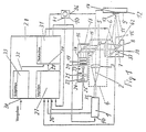
- Fig. 1 is a schematic diagram of a device shows to carry out the procedure, the of a beam source 1, e.g. a solid-state laser Power beam 2 of a laser beam shaping hardening optics 4 is supplied in which it is from a lens 3 to a partially transparent Deflecting mirror 5 deflected and after deflection 90 ° through the latter via a further lens 6 onto one controllable in terms of its deflection speed (arrow 7) Vibration mirror 8 is directed.
- a beam source 1 e.g. a solid-state laser Power beam 2 of a laser beam shaping hardening optics 4
- a beam source e.g. a solid-state laser Power beam 2 of a laser beam shaping hardening optics 4
- a beam source 1 e.g. a solid-state laser Power beam 2 of a laser beam shaping hardening optics 4
- a beam source 1 e.g. a solid-state laser Power beam 2 of a laser beam shaping hardening optics 4
- the power beam 2 is on the surface 9 one movable by a drive motor 10 (see double arrow 11) Workpiece 12 in such a way to harden the latter focused a beam spot that the impact 14 of the Working laser beam spot 13 during curing by the Deflection movement of the oscillating mirror 8 transversely to the feed direction 11 of the workpiece 12 oscillates.
- the lens 20 and the pinhole 21 are, as can be seen from the double arrows 23 and 24 is in the beam direction or perpendicular to it back and forth.
- the IR detector 22 is always exactly the temperature at each point of impact 14 of the working laser beam spot measured immediately.
- the input 26 of the control circuit 27 of the controller 28 is still with the output 35 of the beam source 1, the output 36 of the drive motor generating the feed movement 10 and the output 37 of a drive 38 in terms of its Deflection speed controllable deflection mirror 8 for recording the actual beam power or the actual feed movement or the actual beam deflection.
- the input 34 of the control loop processing setpoints 33 of the controller 28 are used as processing-specific specifications, from which the required temperatures or required Have the energy supply determined, e.g. Material properties, the hardening depth, the heating and cooling time, the Workpiece geometry, the deflection movement, the feed movement and entered the processing time.
- the output 39 of the control loop of the controller 28, in which the actual values and target values entered via input 30 After their comparison, the required manipulated variables are generated be with the input 40 of the beam source 1, the Input 41 of the drive motor 10 and input 42 of the drive 38 of the oscillating mirror 8 for controlling the laser beam energy or the feed movement or the beam deflection connected.
- Temperatures caused by changes in component geometry and the resulting volume and / or material distribution are caused by means of the controller's computer 28 the component location - and shape calculated Identification of the characteristic component geometry special treatment algorithms required for each Treatment situation targeted by the controller 28 used.
- the special treatment algorithms targeted for throttling the energy supply at critical parts of the component such as edges, Tips, holes and the like used.
- the controller 28 analyzes the temperature measurement data determined continuously whether the proportionality of the deviation of the controlled variable (Temperature) and the manipulated variables (laser power; Deflection movement of the deflection mirror; Feed movement) maintained is. If a temperature value (controlled variable) is below of a set threshold, although the laser power (manipulated variable) increases, so when used the processing / measuring range of the system immediately of the controller in different subsystems / areas divided, for which on the one hand the proportionality of the Deviation from controlled variable and manipulated variable as previously applies and in which, on the other hand, at a high deflection speed only enter a relatively small amount of energy becomes.
- the further similar schematic representations of workpiece 12 with associated laser beam guidance 2 or beam spot 13 show a method according to the method adapted edge treatment for double-sided radiation detect an edge of the workpiece 12.
- the angle of incidence ⁇ of the laser beam based on the Edge sides can be variable.
- the distance can also the hardness optics 4 can be changed to the workpiece 12 (FIG. 8) or be constant (Fig. 10).
- FIG. 11 shows a side view of the workpiece 12 with an associated one Laser beam 2, which is perpendicular to the workpiece surface hits, the angle of incidence ⁇ also varies can be.
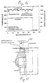
- Fig. 11 was a temperature course over the track width determined how this can be seen in the diagram of FIG. 12 is where the beam position is plotted against temperature is. 120 measurements are shown Measuring frequency of 60 Hz corresponds to a process duration of 2s. The position of the edge is at beam position 13, as can be seen from Fig. 12.
- FIG. 13 shows a schematic sectional view of one exposed to oxide-free curing workpiece 12 with a Blind hole and eight over the circumference of the workpiece in the Distance from each other arranged threaded holes in a Direction of the working laser beam according to arrow 45.
- the diagram associated with FIG. 13 of FIG. 14 is the laser power in W, the relative temperature in mV and the processing time plotted in s, the circumference of the workpiece hardened over 360 ° at a feed rate of 0.1 m / min has been.
Landscapes
- Physics & Mathematics (AREA)
- Optics & Photonics (AREA)
- Engineering & Computer Science (AREA)
- Plasma & Fusion (AREA)
- Mechanical Engineering (AREA)
- Laser Beam Processing (AREA)
Description
Die Erfindung betrifft ein Verfahren zur Geometrieerkennung und - verfolgung mittels ortsaufgelöster Temperaturmessung bei der thermischen Bearbeitung eines Bauteils mittels Laserstrahlung, insbesondere beim Umwandlungshärten mit Laserstrahlung, wobei das Temperaturfeld des Bauteils auf berührungslosem Wege mittels eines photothermischen Sensorsystems erfaßt wird.The invention relates to a method for geometry detection and tracking by means of spatially resolved temperature measurement during the thermal processing of a component by means of Laser radiation, especially in the case of transformation hardening with laser radiation, the Temperature field of the component in a contactless way by means of a photothermal Sensor system is detected.
Die Erfindung betrifft ferner ein Verfahren zum Härten von Werkstückoberflächen mittels Strahlen, insbesondere mittels Laserstrahlen, bei dem eine laserstrahlformende Härteoptik und die Werkstückoberfläche relativ zueinander bewegt werden, der Auftreffort des Arbeitslaserstrahlflecks während des Härtens durch Ablenkbewegung von Strahlumformungseinrichtungen der Härteoptik quer zur Vorschubrichtung oszilliert, und die Temperaturstrahlung des quer zur Vorschubeinrichtung oszillierenden Auftreffortes des Arbeitslaserstrahlflecks mittels teildurchlässiger Spiegel kolinear zum Strahlengang des Arbeitslasers durch die Härteoptik hindurch einer Temperaturkontrolleinrichtung zugeführt wird, von der stets momentan die Temperatur im Auftreffort des Arbeitslaserstrahlflecks erfaßt wird, die ermittelten Temperaturmeßdaten einem mit der Strahlquelle, der Strahlablenkung und der Vorschubbewegung gekoppelten Regler eingegeben werden, in dem eine Temperaturverteilung quer zur Vorschubrichtung ermittelt wird und über den eine darauf abgestimmte Verteilung der Laserstrahlenergie und eine angepaßte Steuerung der Ablenkbewegung der Strahlumformungseinrichtungen der Härteoptik und der Vorschubbewegung unter Berücksichtigung bearbeitungsspezifischer Vorgaben erfolgen. The invention further relates to a method for hardening workpiece surfaces by means of Beams, in particular by means of laser beams, in which a laser beam shaping hardness optics and the workpiece surface are moved relative to each other, the impact of the Working laser beam spot during hardening by deflecting movement of Beam shaping devices of the hardening optics oscillate transversely to the feed direction, and the Thermal radiation of the impingement of the oscillating transverse to the feed device Working laser beam spot with partially transparent mirror colinear to the beam path of the Working laser is fed through the hardening optics through a temperature control device, from which the temperature at the point of impact of the working laser beam spot is always recorded, the determined temperature measurement data one with the beam source, the beam deflection and the Feed motion coupled controller can be entered in which a temperature distribution is determined transversely to the feed direction and by means of which a distribution of the Laser beam energy and customized control of the deflection movement Beam forming equipment of the hardness optics and the feed movement under Processing-specific requirements are taken into account.
Nach der GB 2 196 155 A ist es beim Härten von Kohlenstoffstahl mittels Laserstrahlung bekannt, das Temperaturfeld eines gehärteten Bauteils mittels eines photothermischen Sensorsystems, das einen Infrarotdetektor und einen Konverter zur Anzeige der Temperatur des gehärteten Bauteils aufweist, berührungslos zu erfassen, wobei über eine Plottereinrichtung die Temperaturveränderungen des Bauteils aufgezeichnet werden. Aus letzteren werden z.B. die maximale Härte und die Härtetiefe bestimmt, und die Stärke und/oder Geschwindigkeit des Laserstrahls kann zur Erzielung der erwünschten Charakteristika des Härtens entsprechend eingestellt werden.According to GB 2 196 155 A, it is when hardening carbon steel using laser radiation known, the temperature field of a hardened component by means of a photothermal Sensor system that includes an infrared detector and a converter for displaying the temperature of the has hardened component to record without contact, the via a plotter device Temperature changes of the component are recorded. The latter are e.g. the maximum hardness and depth of hardness determined, and the strength and / or speed of the Laser beam can be used to achieve the desired hardening characteristics accordingly can be set.
Das Umwandlungshärten mittels Laserstrahlung ermöglicht im Vergleich zu herkömmlichen Härteverfahren eine Verringerung der Wärmeeinbringung in das Bauteil und damit eine Verminderung des Bauteilverzuges. Der Einsatz einer faseroptischen Strahlübertragung bedingt ferner eine hohe Flexibilität der Bearbeitungseinrichtung und eine verhältnismäßig leichte Integration des Laserstrahlhärtens in bestehende Anlagen. Hierbei können Arbeitsabläufe effektiv umgestaltet werden, so daß der Aufwand bei einzelnen Arbeitsschritten verringert oder diese vollkommen eingespart werden können. So müssen z.B. beim Randschichthärten im Werkzeugbau derzeit noch Großwerkzeuge, beispielsweise Beschnittwerkzeuge, für die Ofenhärtung demontiert und nach einer häufig aufwendigen Nacharbeit wieder montiert werden. Das Randschichthärten mittels Laserstrahlung bietet hierbei den Vorteil, das zum einen wegen des verhältnismäßig geringen Werkzeugverzuges beim Laserhärten im Vergleich zur herkömmlichen Flamm- oder Ofenhärtung die erforderliche Nacharbeit nach dem Härten reduziert wird. Zum anderen ermöglichen eine flexible Strahlführung sowie eine kompakte Bearbeitungsoptik die Bearbeitung des Werkzeugs im montierten Zustand, wodurch zusätzlich der Aufwand der Demontage und Wiedermontage entfällt.The transformation hardening by means of laser radiation enables compared to conventional ones Hardening process a reduction in the heat input into the component and thus a Reduction of component warpage. The use of fiber-optic beam transmission requires also a high flexibility of the processing device and a relatively light Integration of laser beam hardening in existing plants. Here, workflows be effectively redesigned so that the effort in individual work steps is reduced or these can be saved completely. For example, during surface hardening in Toolmaking currently still has large tools, such as trimming tools, for the Oven hardening dismantled and reassembled after a frequently complex rework. The edge layer hardening by means of laser radiation offers the advantage here, on the one hand the relatively small warpage in laser hardening compared to conventional flame or furnace hardening the necessary rework after hardening is reduced. On the other hand, flexible beam guidance as well as compact allow Machining optics the machining of the tool in the assembled state, which additionally the effort of disassembly and reassembly is eliminated.
Die benannten Vorteile werden jedoch in vielen Fällen relativiert, wenn aufgrund komplexer Werkstückgeometrien ein hoher Aufwand zur Programmierung der Bahn des Bearbeitungskopfes erforderlich ist. Die große Anzahl verschiedenartiger Werkzeuggeometrien sowie eine hohe Erneuerungsrate bei Werkzeugen reduzieren hierbei die Wiederverwendungsmöglichkeit einmal sehr aufwendig programmierter Bahnen.However, the named advantages are relativized in many cases, if due to more complex ones Workpiece geometries require a lot of effort to program the path of the machining head is required. The large number of different tool geometries as well as a high one Renewal rates for tools reduce the possibility of reuse once very complexly programmed tracks.
Abhilfe schafft die Ankopplung von Zusatzeinrichtungen, bestehend aus einem zusätzlichen, externen Bahnsensor und gegebenenfalls einem Aktor, welche eine automatische Nachführung des Bearbeitungswerkzeuges gestatten. Damit ist jedoch ein erhöhter Aufwand verbunden. Außerdem besteht die Schwierigkeit der Anpassung und Anbindung an das vorhandene Bearbeitungssystem, und in aller Regel ist eine verringerte Zugänglichkeit durch einen weniger kompakten Aufbau des Bearbeitungswerkzeugs gegeben.This is remedied by the coupling of additional devices, consisting of an additional external path sensor and, if necessary, an actuator, which has automatic tracking allow the editing tool. However, this involves an increased effort. There is also the difficulty of adapting and connecting to the existing one Machining system, and usually is a reduced accessibility by a less given compact construction of the machining tool.
Der Erfindung liegt die Aufgabe zugrunde, bei der thermischen Bearbeitung von Bauteilen mittels Laserstrahlung, insbesondere beim Umwandlungshärten mit Laserstrahlung, unter Vermeidung der oben genannten Nachteile dafür zu sorgen, daß in ökonomischer und effektiver Weise eine Geometrieerkennung und - verfolgung des zu bearbeitenden Bauteils möglich ist.The invention has for its object in the thermal processing of components by means of laser radiation, in particular during transformation hardening with laser radiation, under Avoiding the above drawbacks to ensure that it is economical and effective A geometry recognition and tracking of the component to be machined is possible.
Diese Aufgabe wird erfindungsgemäß dadurch gelöst, daß die Erfassung des im Bauteil durch die Prozeßwärme erzeugten Temperaturfeldes in seiner zweidimensionalen Projektion erfolgt, basierend auf Variationen der durch Änderung der Bauteilgeometrie und der dadurch bedingten Volumen- und/oder Materialverteilung hervorgerufenen lokalen Wärmeleitung aus den ermittelten Daten des Temperaturfeldes die Bauteillage und - gestalt berechnet werden und nach Identifikation der charakteristischen Bauteilgeometrie spezielle Behandlungsalgorithmen für die jeweiligen erforderlichen Behandlungssituationen zielgerichtet eingesetzt werden.This object is achieved in that the detection of in the component by the process heat generated temperature field takes place in its two-dimensional projection, based on variations in and caused by changes in component geometry Volume and / or material distribution caused local heat conduction from the determined data of the temperature field the component position and shape are calculated and after Identification of the characteristic component geometry special treatment algorithms for the the respective required treatment situations can be used in a targeted manner.
Vorzugsweise werden die speziellen Behandlungsalgorithmen zielgerichtet zur Drosselung der Energiezufuhr an kritischen Stellen des Bauteils wie Kanten, Spitzen, Bohrungen und dgl. eingesetzt. The special treatment algorithms are preferably targeted for throttling the Energy supply at critical parts of the component such as edges, tips, bores and the like. used.
Die Identifikation einer Bauteilkante und deren Lage zum Bearbeitungssystem kann zur Steuerung eines Aktors genutzt werden derart, daß die Lage der Bearabeitungszone durch einen Soll-Ist-Vergleich korrigiert wird und somit eine Positionsregelung auf der Basis eines photothermischen Sensors möglich ist. Als Aktor kann ein gesteuerter Schwingspiegelantrieb verwendet werden. Auch können die der Identifikation der Bauteile entsprechenden speziellen Behandlungsalgorithmen für die Bahnführung eines Roboters eingesetzt werden.The identification of a component edge and its position in relation to the processing system can be used for Control of an actuator can be used such that the location of the processing zone by a Target-actual comparison is corrected and thus a position control based on a photothermal sensor is possible. A controlled oscillating mirror drive can act as an actuator be used. The special ones corresponding to the identification of the components can also be used Treatment algorithms for the path guidance of a robot can be used.
Das erfindungsgemäße Verfahren nach dem Oberbegriff des Patentanspruchs 7 zeichnet sich
dadurch aus, daß die ermittelten Temperaturmeßdaten fortlaufend dahingehend analysiert
werden, ob die Proportionalität der Abweichung der Regelgröße (Temperatur) und der
Stellgrößen (Laserleistung; Ablenkbewegung der Strahlumformungseinrichtungen;
Vorschubbewegung) gewahrt ist, und im Fall, daß ein Temperaturwert unterhalb eines
festgelegten Schwellenwerts ermittelt wird, obwohl die Laserleistung erhöht worden ist, was
insbesondere an Kanten auftritt, der Bearbeitungs- / Meßbereich automatisch in unterschiedliche
Teilsysteme / Bereiche aufgeteilt wird, für die einserseits die Proportionalität der Abweichung
von Regelgröße und Stellgrößen wie zuvor gilt und in denen andererseits bei hoher
Ablenkgeschwindigkeit nur eine verhältnismäßig geringe Energiemenge eingetragen wird.The inventive method according to the preamble of
Die Erfindung bringt den Vorteil mit sich, daß die tatsächliche Geometrie bzw. die Materialsverteilung des Bauteils vor der Bearbeitung nicht bzw. nicht exakt vorgegeben werden muß. Durch die selbsttätige Ermittlung der Systemgrenzen ist auch deren Lage im Raum bekannt, so daß die Kenntnis der Bauteilgeometrie z.B. für die Bahnführung des Roboters eingesetzt werden kann, The invention has the advantage that the actual geometry or The material distribution of the component cannot be specified or not exactly specified before processing got to. Due to the automatic determination of the system boundaries, their position in the room is also known, so that knowledge of the component geometry e.g. for the path guidance of the robot can be used
Die Erfindung ermöglicht es, ohne zusätzliche sensorische Einrichtungen direkt aus der Prozeßwärme on-line Informationen über die Lage und die geometrische Gestalt des zu bearbeitenden Bauteils zu gewinnen. Die genaue Kenntnis der Bauteillage und -gestalt erlaubt es, spezifische geometrieabhängige Bearbeitungsalgorithmen anzuwenden und zu kontrollieren und/oder mit Hilfe eines geeigneten Aktors - z.B. eines gesteuerten Schwingspiegels - die tatsächliche Lage an die Soll-Lage anzupassen. Generell ist in jedem Fall ein transientes Temperaturfeld im Bauteil / Werkstück zu induzieren. Je nach Vorgehensweise gibt es zwei prinzipielle Möglichkeiten, um Informationen über die Materialverteilung in dem Bauteil zu erhalten, und zwar:The invention makes it possible without additional sensory Facilities directly from the process heat on-line information about the location and the geometric shape of the winning component. Exact knowledge of Component location and shape allows specific geometry-dependent Apply and control machining algorithms and / or with the help of a suitable actuator - e.g. of a controlled oscillating mirror - the actual position to adapt to the target position. In general, there is one to induce a transient temperature field in the component / workpiece. Depending on the procedure, there are two basic ones Ways to get information about material distribution in the component, namely:
Wird dem Bauteil die Wärme gleichförmig und homogen zugegeführt, so ergeben sich unterschiedliche Temperaturen, so daß die Materialverteilung (Art, Menge, Ausdehnung) durch eine ortsaufgelöste Temperaturmessung ermittelt werden kann.If the component is supplied with heat uniformly and homogeneously, so there are different temperatures, so that the material distribution (type, quantity, extent) by a spatially resolved temperature measurement can be determined.
Es kann aber auch eine homogene Temperaturverteilung im Bauteil erzeugt werden, wozu allerdings eine ortsaufgelöste Energiezufuhr notwendig ist. Aus der räumlichen Verteilung dieser Energiezufuhr lassen sich ebenfalls Rückschlüsse auf die Materialverteilung ziehen. Als zusätzliche Information in diesem Fall können auch die verbleibenden Regelabweichungen des Temperatursignals dienen, da diese prinzipbedingt nie zu Null werden können.But it can also be a homogeneous temperature distribution in the Component are generated, but for this a spatially resolved Energy supply is necessary. From the spatial distribution conclusions can also be drawn from this energy supply pull the material distribution. As additional information in this case, the remaining control deviations can also serve the temperature signal, since this is due to the principle can never go to zero.
Die Erfindung wird nun anhand der Zeichnungen erläutert. In diesen sind:
- Fig. 1
- eine prinzipielle blockschaltbildartige Darstellung einer Vorrichtung zur Durchführung des Verfahrens der Erfindung,
- Fig. 2 bis Fig. 5
- schematische Draufsichtdarstellungen eines Werkstücks mit zugeordnetem Strahlfleck, die die Kantenerkennung und -verfolgung bei einseitiger Bestrahlung einer Werkstückkante verdeutlichen sollen,
- Fig. 6 bis Fig. 10
- weitere ähnliche schematische Darstellungen des Werkstücks mit zugeordneter Laserstrahlführung bzw. zugeordnetem Strahlfleck, die eine angepaßte Kantenbehandlung bei nicht nur einseitiger Bestrahlung einer Kante verdeutlichen sollen,
- Fig. 11
- eine Seitenansicht des Werkstücks mit zugeordnetem Laserstrahl bei der Kantenerkennung,
- Fig. 12
- ein Diagramm, aus dem der Temperaturverlauf über die Spurbreite hervorgeht,
- Fig. 13
- eine schematische Schnittansicht eines zu härtenden, mit Gewindebohrungen versehenen Werkzeugteils,
- Fig. 14
- ein Diagramm, aus dem die Laserleistung und die relative Temperatur über die Bearbeitungsdauer eines Werkstücks gemäß Fig. 13 hervorgeht, und
- Fig. 15
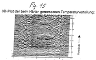
- ein 3D-Plot der beim Härten über zwei Bohrungen hinweg gemesenene Temperaturverteilung
- Fig. 1
- 2 shows a basic block diagram representation of a device for carrying out the method of the invention,
- 2 to 5
- schematic top view representations of a workpiece with an assigned beam spot, which are intended to clarify the edge detection and tracking with one-sided irradiation of a workpiece edge,
- 6 to 10
- further similar schematic representations of the workpiece with assigned laser beam guidance or assigned beam spot, which are intended to illustrate an adapted edge treatment when not only irradiating an edge on one side,
- Fig. 11
- a side view of the workpiece with an associated laser beam during edge detection,
- Fig. 12
- a diagram showing the temperature profile over the track width,
- Fig. 13
- 2 shows a schematic sectional view of a tool part to be hardened and provided with threaded bores,
- Fig. 14
- FIG. 13 shows a diagram from which the laser power and the relative temperature over the processing time of a workpiece are shown, and
- Fig. 15
- a 3D plot of the temperature distribution measured during hardening across two holes
Wie aus Fig. 1 hervorgeht, die ein Prinzipbild einer Vorrichtung
zur Durchführung des Verfahrens zeigt,wird der von
einer Strahlquelle 1, z.B. einem Festkörperlaser kommende
Leistungsstrahl 2 einer laserstrahlformenden Härteoptik 4
zugeführt wird, in der er von einer Linse 3 auf einen teildurchlässigen
Umlenkspiegel 5 gelenkt und nach Umlenkung um
90° durch letzteren über eine weitere Linse 6 auf einen
hinsichtlich seiner Ablenkgeschwindigkeit (Pfeil 7) steuerbaren
Schwingspiegel 8 gerichtet wird. Von dem Schwingspiegel
8 wird der Leistungsstrahl 2 auf die Oberfläche 9
eines von einem Antriebsmotor 10 bewegbaren (siehe Doppelpfeil
11) Werkstücks 12 derart zum Härten des letzteren zu
einem Strahlfleck fokussiert, daß der Auftreffort 14 des
Arbeitslaserstrahlflecks 13 während des Härtens durch die
Ablenkbewegung des Schwingspiegels 8 quer zur Vorschubrichtung
11 des Werkstücks 12 oszilliert.As is apparent from Fig. 1, which is a schematic diagram of a device
shows to carry out the procedure, the of
a
Die unmittelbar vom jeweiligen Auftreffort 14 des Arbeitslaserstrahlflecks
13 kommende Temperaturstrahlung 15 wird
kolinear zum Strahlgang 2 des Arbeitslasers 1 durch die
Härteoptik 4 hindurchgeführt, d.h. sie verläuft, wie aus
Fig. 1 ersichtlich, vom Auftreffort 14 des Arbeitslaserstrahlflecks
13 zum Schwingspiegel 8 und von diesem über
die Linse 6 zu dem teildurchlässigen Spiegel 5 der Härteoptik
4, durch den sie hindurchtritt und auf einen Umlenkspiegel
16 einer Temperaturkontrolleinrichtung 17 gelangt.
Nach Umlenkung um 90° in der Temperaturkontrolleinrichtung
durch den Umlenkspiegel 16 wird die Temperaturstrahlung
durch eine Anordnung aus einem Bandpaßfilter 18, einer Blende
19 und einer Linse 20 gelenkt und von letzterer auf
eine Lochblende 21 fokussiert, der in Strahlrichtung ein
IR-Detektor 22 nachgeordnet ist.Die Linse 20 und die Lochblende
21 sind, wie aus den Doppelpfeilen 23 bzw. 24 ersichtlich
ist, in Strahlrichtung bzw. senkrecht zu dieser
hin- und herbeweglich. Von dem IR-Detektor 22 wird stets
exakt die Temperatur in jedem Auftreffpunkt 14 des Arbeitslaserstrahlflecks
unmittelbar gemessen.The directly from the
Mit dem IR-Detektor 22 und damit mit dem Ausgang 25 der
Temperaturkontrolleinrichtung 17 ist ein Eingang 26 eines
Istgrößen verarbeitenden Regelkreises 27 eines Reglers 28
verbunden, dessen Ausgang 29 wiederum mit dem Eingang 30
eines Stellgrößen erzeugenden Regelkreises 31 des Reglers
verbunden ist. Der Eingang 30 des Regelkreises 31 ist weiterhin
mit dem Ausgang 32 eines weiteren Sollgrößen verarbeitenden
Regelkreises 33 des Reglers 28 verbunden, in dessen
Eingang 34 bearbeitungsspezifische Vorgaben als Bearbeitungsparameter
eingebbar sind.With the
Der Eingang 26 des Regelkreises 27 des Reglers 28 ist weiterhin
mit dem Ausgang 35 der Strahlquelle 1,dem Ausgang 36
des die Vorschubbewegung erzeugenden Antriebsmotors 10 und
dem Ausgang 37 eines Antriebs 38 des hinsichtlich seiner
Ablenkgeschwindigkeit steuerbaren Ablenkspiegels 8 zur Aufnahme
der Ist-Strahlleistung bzw. der Ist-Vorschubbewegung
bzw. der Ist-Strahlablenkung verbunden.The
Dem Eingang 34 des Sollgrößen verarbeitenden Regelkreises
33 des Reglers 28 werden als bearbeitungsspezifische Vorgagaben,
aus denen sich die geforderten Temperaturen oder geforderte
Energiezufuhr bestimmen lassen,z.B. Materialeigenschaften,
die Einhärttiefe, die Erwärmungs- und Abkühlungsdauer,die
Werkstücksgeometrie,die Auslenkbewegung, die Vorschubbewegung
und die Bearbeitungszeit eingegeben.The
Der Ausgang 39 des Regelkreises des Reglers 28, in dem aus
den über den Eingang 30 eingegebenen Istgrößen und Sollgröβen
nach deren Abgleich die erforderlichen Stellgrößen erzeugt
werden, ist mit dem Eingang 40 der Strahlquelle 1, dem
Eingang 41 des Antriebsmotors 10 und dem Eingang 42 des Antriebs
38 des Schwingspiegels 8 zur Steuerung der Laserstrahlenergie
bzw. der Vorschubbewegung bzw. der Strahlablenkung
verbunden.The output 39 of the control loop of the
Basierend auf den Variationen der stets in den Auftrefforten
14 des Arbeitslaserstrahlflecks 13 momentan gemessenen
Temperaturen, die durch Änderungen der Bauteilgeometrie und
die dadurch bedingte Volumen- und/oder Materialverteilung
hervorgerufen werden, wird mittels des Rechners des Reglers
28 die Bauteillage - und gestalt berechnet.Entsprechend der
Identifikation der charakteritsichen Bauteilgeometrie werden
spezielle Behandlungsalgorithmen für die jeweilige erforderlich
Behandlungssituation zielgerichtet von dem Regler
28 zum Einsatz gebracht. So werden z.B. die sepziellen Behandlungsalgorithmen
zielgerichtet zur Drosselung der Energiezufuhr
an kritischen Stellen des Bauteils wie Kanten,
Spitzen, Bohrungen und dergleichen eingesetzt.Based on the variations of always in the meeting places
14 of the working
Der Regler 28 analysiert die ermittelten Temperaturmeßdaten
fortlaufend, ob die Proportionalität der Abweichung der Regelgröße
(Temperatur) und der Stellgrößen (Laserleistung;
Ablenkbewegung des Ablenkspiegels; Vorschubbewegung) gewahrt
ist. Wird ein Temperaturwert (Regelgröße) unterhalb
eines festgelegten Schwellwertes festgestellt, obwohl sich
die Laserleistung (Stellgröße) erhöht, so wird bei Ausnutzung
des Systems sofort automatisch der Bearbeitungs- /Meßbereich
des Reglers in unterschiedliche Teilsysteme /Bereiche
aufgeteilt, für die einerseits die Proportionalität der
Abweichung von Regelgröße und Stellgröße wie bisher gilt
und in denen andererseits bei hoher Ablenkgeschwindigkeit
nur eine verhältnismäßig geringe Energiemenge eintragen
wird.The
Aus den Fig. 2 bis 4, die schematisch Draufsichten auf ein
Werkstück 12 mit zugeordnetem Arbeitslaserstrahlfleck 13
zeigen, geht die Erkennung der Kantenposition im Strahlfleck
13 bei unterschiedlichen Bewegungsrichtungen (Pfeil 43) des
Strahlflecks 13 zum Werkstück 12 hervor. Das an der Kantenposition
über den Strahlfleck auf berührungslosem Weg ermittelte,
deutlich veränderte Temperaturfeld und die verfahrensgemäße
Ermittlung eines Temperaturwertes unterhalb
eines festgelegten Schwellwertes trotz einer Erhöhung der
Laserleistung führt zur automatischen Aufteilung des Bearbeitungs-
/ Meßbereichs des Reglers in unterschiedliche
Teilsysteme / Bereiche des letzteren derart,daß eine besondere
Behandlung der Kantengeometrie erfolgt, um diese z.B.
vor Aufschmelzungen zu schützen. Verfahrensgemäß ist auch
die Kantenposition bezüglich der Bearbeitungsmaschine (Härteoptik)
bestimmbar. Wie aus Fig. 5 ablesbar ist,können die
Positionen von Strahlfleck und Kante durch Veränderung der
Strahlfleckposition über angepaßte Scanbewegung relativ zueinander
konstant gehalten werden. In Fig. 5 ist die beispielhafte
Bahn der Führungsmaschine, die auch nichtlinear
sein kann, mit "44" gekennzeichnet.2 to 4, the schematic plan views of a
Die Fig. 6 bis 10, die weitere ähnliche schematische Darstellungen
des Werkstücks 12 mit zugeordneter Laserstrahlführung
2 bzw. Strahlfleck 13 zeigen, lassen eine verfahrensgemäße
angepaßte Kantenbehandlung bei zweiseitiger Bestrahlung
einer Kante des Werkstücks 12 erkennen. Hierbei
kann der Auftreffwinkel α des Laserstrahls bezogen auf die
Kantenseiten (Fig. 6) variabel sein. Auch kann der Abstand
der Härteoptik 4 zum Werkstück 12 veränderbar (Fig. 8) bzw.
konstant (Fig. 10) sein.6 to 10, the further similar schematic representations
of
Fig. 11 zeigt eine Seitenansicht der Werkstücks 12 mit zugeordnetem
Laserstrahl 2, der senkrecht auf die Werkstückoberfläche
trifft, wobei der Auftreffwinkel α auch variiert
werden kann. Bei der verfahrensgemäßen Kantenerkennung gemäß
Fig. 11 wurde ein Tepmeraturverlauf über die Spurbreite
ermittelt, wie dieser in dem Diagramm der Fig. 12 zu sehen
ist, in dem die Strahlposition über die Temperatur aufgetragen
ist. Dargestellt sind 120 Messungen, was bei einer
Meßfrequenz von 60 Hz einer Prozeßdauer von 2s entspricht.
Die Lage der Kante befindet sich bei der Strahlposition 13,
wie aus Fig. 12 ersichtlich ist.11 shows a side view of the
Fig. 13 zeigt eine schematische Schnittansicht eines einer
oxidfreien Härtung ausgesetzten Werkstücks 12 mit einer
Sacklochbohrung und acht über den Umfang des Werkstücks im
Abstand zueinander angeordneten Gewindebohrungen bei einer
Richtung des Arbeitslaserstrahls gemäß Pfeil 45. In dem der
Fig. 13 zugeordneten Diagramm der Fig. 14 sind die Laserleistung
in W, die relative Temperatur in mV und die Bearbeitungsdauer
in s aufgetragen,wobei der Umfang des Werkstücks
über 360° bei einem Vorschub von 0,1 m/min gehärtet
wurde.13 shows a schematic sectional view of one
exposed to oxide-
Fig. 15 zeigt schließlich einen 3D - Plot der beim Härten über zwei Bohrungen hinweg gemessenen Temperaturverteilung. 15 finally shows a 3D plot of the hardening process Temperature distribution measured over two holes.
- 11
- Strahlquelle, FestkörperlaserBeam source, solid-state laser
- 22
- Leistungsstrahl, Strahlengang des ArbeitslasersPower beam, beam path of the working laser
- 33
- Linselens
- 44
- Härteoptikhardness optics
- 55
- teildurchlässiger Umlenkspiegelpartially permeable deflecting mirror
- 66
- Linselens
- 77
- Pfeil für AblenkgeschwindigkeitDeflection speed arrow
- 88th
- Schwingspiegeloscillating mirror
- 99
- WerkstückoberflächeWorkpiece surface
- 1010
- Antriebsmotordrive motor
- 1111
- Doppelpfeil für VorschubrichtungenDouble arrow for feed directions
- 1212
- Werkstückworkpiece
- 1313
- ArbeitslaserstrahlfleckWork laser beam spot
- 1414
- Auftreffortimpingement
- 1515
- Temperaturstrahlungthermal radiation
- 1616
- Umlenkspiegeldeflecting
- 1717
- TemperaturkontrolleinrichtungTemperature control device
- 1818
- Bandpaßfilterbandpass filter
- 1919
- Blendecover
- 2020
- Linselens
- 2121
- Lochblendepinhole
- 2222
- IR-DetektorIR detector
- 2323
-
Doppelpfeil für Bewegung der Linse 20Double arrow for movement of the
lens 20 - 2424
-
Doppelpfeil für Bewegung der Lochblende 21Double arrow for movement of
pinhole 21 - 2525
- Ausgang der TemperaturkontrolleinrichtungOutput of the temperature control device
- 2626
-
Eingang des Regelkreises 27Input of
control loop 27 - 2727
- Regelkreis für IstgrößenControl loop for actual values
- 2828
- Reglerregulator
- 2929
- Ausgang des Regelkreises für IstgrößenOutput of the control loop for actual values
- 3030
-
Eingang des Regelkreises 31 für StellgrößenInput of the
control circuit 31 for manipulated variables - 3131
- Regelkreis für Stellgrößen Control loop for manipulated variables
- 3232
-
Ausgang des Regelkreises 33 für SollgrößenOutput of the
control circuit 33 for setpoints - 3333
- Regelkreis für SollgrößenControl loop for setpoints
- 3434
-
Eingang des Regelkreises 33 für SollgrößenInput of the
control circuit 33 for setpoints - 3535
-
Ausgang der Strahlquelle 1Output of the
beam source 1 - 3636
-
Ausgang des Antriebsmotors 10Output of the
drive motor 10 - 3737
-
Ausgang des Antriebs 38 des Schwingspiegels 8Output of the
drive 38 of theoscillating mirror 8 - 3838
-
Antrieb des Schwingspiegels 8
Vibration mirror drive 8 - 3939
-
Ausgang des Regelkreises 31 für StellgrößenOutput of the
control circuit 31 for manipulated variables - 4040
-
Eingang der Strahlquelle 1Input of the
beam source 1 - 4141
-
Eingang des Antriebsmotors 10Input of the
drive motor 10 - 4242
-
Eingang des Antriebs 38 des Schwingspiegels 8Input of the
drive 38 of theoscillating mirror 8 - 4343
-
Pfeil für Bewegungsrichtung des Strahlflecks 13Arrow for the direction of movement of the
beam spot 13 - 4444
- Bahn der FührungsmaschinePath of the guiding machine
- 4545
- Pfeil für Richtung des ArbeitslaserstrahlsArrow for direction of the working laser beam
- αα
- Auftreffwinkel des Arbeitslaserstrahls auf WerkstückAngle of incidence of the working laser beam on the workpiece
Claims (7)
- A method for geometry recognition and tracking by means of a locally resolved temperature measurement during the thermal processing of an element (12) by means of laser radiation (2), in particular, during transformation hardening with laser radiation (2), wherein the temperature field of the element (12) is determined in a contactless fashion by means of a photothermal sensor system,
characterized by the fact that
the temperature field generated in the element (12) by the process heat is determined in its two-dimensional projection, by the fact that the element position and shape are calculated from the determined data of the temperature field based on variations in the local thermal conduction caused by changes in the element geometry and the associated volume and/or material distribution, and by the fact that special treatment algorithms for the respectively required treatment situations are purposefully utilized after the identification of the characteristic element geometry. - The method according to Claim 1, characterized by the fact that the special treatment algorithms are purposefully utilized for choking the energy supply to critical points of the element (12), e.g., edges, points, bores and the like.
- The method according to Claims 1 and 2, characterized by the fact that the identification of an element edge and its position relative to the processing system is utilized for controlling an actuator in such a way that the position of the processing zone is corrected based on a nominal/actual comparison and a position control can be realized on the basis of a photothermal sensor.
- The method according to Claim 3, characterized by the fact that a controlled oscillatory mirror drive (38) is used as the actuator.
- The method according to Claims 1-4, characterized by the fact that a homogenous temperature distribution is generated in the element (12) with the aid of a locally resolved energy supply, and by the fact that the material distribution in the element (12) and consequently its shape are determined from the spatial distribution of the energy supply, wherein the unavoidable residual deviations of the temperature signals are utilized as additional information for determining the element position and shape.
- The method according to Claim 1, characterized by the fact that the special treatment algorithms that correspond to the identification of the element geometry are utilized for the path control (44) of a robot.
- A method for hardening work piece surfaces (9) by means of beams (2), in particular, by means of laser beams (2), wherein a hardening optic (4) that forms the laser beam and the work piece surface (9) are moved relative to one another, wherein the point of impact (14) of the laser beam spot (13) oscillates transverse to the advance direction (11) during the hardening process due to deflection movements of beam transformation devices of the hardening optic (4), wherein the thermal radiation (15) of the point of impact (14) of the laser beam spot (13) which oscillates transverse to advance direction (11) is fed by means of partially transparent mirrors (5) to a temperature control device (17) through the hardening optic (4) collinear to the beam path (2) of the laser (1), wherein the temperature control device continuously measures the instantaneous temperature in the point of impact (14) of the laser beam spot (13), wherein the determined temperature measuring data are input into a controller (28) that is coupled to the beam source (1), the beam deflection arrangement and the advance movement mechanism and in which a temperature distribution transverse to the advance direction (11) is determined, and wherein said controller serves for realizing a distribution of the laser beam energy that is adapted to the temperature distribution transverse to the advance direction, as well as a correspondingly adapted control of the deflection movements of the beam transformation devices of the hardening optic (4) and the advance movement, namely by taking into account specific predetermined processing data,
characterized by the fact that
the determined temperature measuring data are continuously analyzed as to the fact whether the proportionality of the deviation of the control variable (temperature) and the adjusting variables (laser power; deflection movement of the beam transformation devices; advance movement) is preserved, and by the fact that the processing/measuring region is automatically divided into different partial systems/regions in case a temperature value is determined below a fixed threshold value although the laser power was increased as it occurs, in particular, on the edges, wherein the proportionality of the deviation of the control variable and the adjusting variables applies to said partial systems/regions as before, and wherein only a comparatively low amount of energy is introduced in these partial systems/regions at a high deflection speed.
Priority Applications (2)
| Application Number | Priority Date | Filing Date | Title |
|---|---|---|---|
| DE59710231T DE59710231D1 (en) | 1997-09-20 | 1997-09-20 | Process for geometry detection and tracking during the thermal processing of components using laser radiation |
| EP19970116420 EP0904886B1 (en) | 1997-09-20 | 1997-09-20 | Process for geometry recognition and tracking during thermal treatment of elements by means of laser beam |
Applications Claiming Priority (1)
| Application Number | Priority Date | Filing Date | Title |
|---|---|---|---|
| EP19970116420 EP0904886B1 (en) | 1997-09-20 | 1997-09-20 | Process for geometry recognition and tracking during thermal treatment of elements by means of laser beam |
Publications (2)
| Publication Number | Publication Date |
|---|---|
| EP0904886A1 EP0904886A1 (en) | 1999-03-31 |
| EP0904886B1 true EP0904886B1 (en) | 2003-06-04 |
Family
ID=8227382
Family Applications (1)
| Application Number | Title | Priority Date | Filing Date |
|---|---|---|---|
| EP19970116420 Expired - Lifetime EP0904886B1 (en) | 1997-09-20 | 1997-09-20 | Process for geometry recognition and tracking during thermal treatment of elements by means of laser beam |
Country Status (2)
| Country | Link |
|---|---|
| EP (1) | EP0904886B1 (en) |
| DE (1) | DE59710231D1 (en) |
Cited By (1)
| Publication number | Priority date | Publication date | Assignee | Title |
|---|---|---|---|---|
| US12191536B2 (en) | 2019-02-25 | 2025-01-07 | Audi Ag | Method for producing a bipolar plate strand, method for producing a bipolar plate and device for carrying out the method |
Families Citing this family (6)
| Publication number | Priority date | Publication date | Assignee | Title |
|---|---|---|---|---|
| DE102004051876A1 (en) * | 2004-10-20 | 2006-04-27 | Fraunhofer-Gesellschaft zur Förderung der angewandten Forschung e.V. | Spot-separable temperature measurement arrangement, used in laser manufacturing process, has optical detector with optical filter for measuring electromagnetic radiation caused by irradiated laser on operating area formed on workpiece |
| DE102009005935B4 (en) | 2009-01-23 | 2010-10-07 | Danfoss Compressors Gmbh | A method of calibrating a connecting rod assembly and connecting rod assembly |
| DE102010010148A1 (en) | 2010-03-04 | 2010-10-14 | Daimler Ag | Method for coating bearing materials with a filler material by a laser beam, comprises supplying the filler material as flat band or flat powder beam and aligning the laser beam with respect to its width on a width of the filler material |
| CN111551071A (en) * | 2020-04-30 | 2020-08-18 | 西安工业大学 | Testing device and three-dimensional reconstruction method for detonation temperature field of micro-explosive device |
| CN113686241B (en) * | 2021-08-06 | 2022-06-14 | 大连理工大学 | An error analysis method for high temperature surface line laser geometric measurement |
| CN119511056B (en) * | 2024-10-18 | 2025-08-05 | 武汉铱科赛科技有限公司 | Blind hole reliability testing method, equipment, device and system |
Family Cites Families (2)
| Publication number | Priority date | Publication date | Assignee | Title |
|---|---|---|---|---|
| JPS62136039A (en) * | 1985-12-09 | 1987-06-19 | Rohm Co Ltd | Defect-marking method for semiconductor chip |
| GB2196155B (en) * | 1986-09-20 | 1991-02-20 | Mitsubishi Electric Corp | Control apparatus for energy beam hardening |
-
1997
- 1997-09-20 EP EP19970116420 patent/EP0904886B1/en not_active Expired - Lifetime
- 1997-09-20 DE DE59710231T patent/DE59710231D1/en not_active Expired - Lifetime
Cited By (1)
| Publication number | Priority date | Publication date | Assignee | Title |
|---|---|---|---|---|
| US12191536B2 (en) | 2019-02-25 | 2025-01-07 | Audi Ag | Method for producing a bipolar plate strand, method for producing a bipolar plate and device for carrying out the method |
Also Published As
| Publication number | Publication date |
|---|---|
| DE59710231D1 (en) | 2003-07-10 |
| EP0904886A1 (en) | 1999-03-31 |
Similar Documents
| Publication | Publication Date | Title |
|---|---|---|
| EP0707920B1 (en) | Compact laser processing head for laser processing of material, with an integrated on-line track control | |
| EP2544849B1 (en) | Laser machning head und method of machining a workpiece using a laser beam | |
| EP2691206B1 (en) | Method for machining a workpiece by means of a laser beam | |
| EP0819036B1 (en) | Process and device for laser machining of any 3d surface | |
| EP0060980A1 (en) | Device for cutting by means of a laser beam | |
| DE4206584C2 (en) | Device and method for connecting two components by means of ultrasound | |
| EP0700325A1 (en) | METHOD FOR PROCESSING MATERIAL WITH DIODE RADIATION | |
| EP1424613A1 (en) | method and device for machining a workpiece | |
| EP1640101A2 (en) | Method and device for controlling an automated machining process | |
| EP2027962A1 (en) | Welding device and method for orbital welding of pipes | |
| DE4014251A1 (en) | METHOD AND SYSTEM FOR TRACKING GOODS CONTROL | |
| DE19615069A1 (en) | Procedure for panning machine tool esp. laser beam cutter using edge tracking on workpiece | |
| DE4316829A1 (en) | Method of machining material by diode radiation | |
| EP0187934A2 (en) | Device for processing workpieces by a laser beam emerging out of a laser's head | |
| DE102014101568A1 (en) | Method and apparatus for laser welding or cutting with a dynamically adaptable analysis area | |
| EP0904886B1 (en) | Process for geometry recognition and tracking during thermal treatment of elements by means of laser beam | |
| EP0309973B1 (en) | Process for thermal treating of workpieces in solid state by a laser beam | |
| DE19853733C1 (en) | Local heat treatment of workpiece surfaces by laser beam involves locally resolved temperature measurement on the laser spot or its direct vicinity, and control of the laser output power | |
| EP2091699B1 (en) | Method and device for fine-positioning a tool having a handling device | |
| DE112021003769T5 (en) | laser processing system | |
| EP0822027B2 (en) | Method of hardening the surface of a workpiece using a beam, particularly a laser beam and device for executing this method | |
| DE102008013398A1 (en) | Programming and control of remote equipment for e.g. laser-processing and handling of workpieces, positions workpiece taking accessibility into account | |
| EP4126434B1 (en) | Method of determining welding parameters for a welding process on a workpiece and welding device for carrying out a welding process on a workpiece with fixed welding parameters | |
| WO2000076715A2 (en) | Device for determining the position of emission zones of a thermal process with locally limited energy supply | |
| DE10355051B4 (en) | Method and apparatus for laser beam welding with reduced marking |
Legal Events
| Date | Code | Title | Description |
|---|---|---|---|
| PUAI | Public reference made under article 153(3) epc to a published international application that has entered the european phase |
Free format text: ORIGINAL CODE: 0009012 |
|
| AK | Designated contracting states |
Kind code of ref document: A1 Designated state(s): CH DE FR GB IT LI NL SE |
|
| 17P | Request for examination filed |
Effective date: 19990927 |
|
| AKX | Designation fees paid |
Free format text: CH DE FR GB IT LI NL SE |
|
| 17Q | First examination report despatched |
Effective date: 20011024 |
|
| GRAH | Despatch of communication of intention to grant a patent |
Free format text: ORIGINAL CODE: EPIDOS IGRA |
|
| GRAH | Despatch of communication of intention to grant a patent |
Free format text: ORIGINAL CODE: EPIDOS IGRA |
|
| GRAA | (expected) grant |
Free format text: ORIGINAL CODE: 0009210 |
|
| AK | Designated contracting states |
Designated state(s): CH DE FR GB IT LI NL SE |
|
| PG25 | Lapsed in a contracting state [announced via postgrant information from national office to epo] |
Ref country code: NL Free format text: LAPSE BECAUSE OF FAILURE TO SUBMIT A TRANSLATION OF THE DESCRIPTION OR TO PAY THE FEE WITHIN THE PRESCRIBED TIME-LIMIT Effective date: 20030604 Ref country code: IT Free format text: LAPSE BECAUSE OF FAILURE TO SUBMIT A TRANSLATION OF THE DESCRIPTION OR TO PAY THE FEE WITHIN THE PRESCRIBED TIME-LIMIT;WARNING: LAPSES OF ITALIAN PATENTS WITH EFFECTIVE DATE BEFORE 2007 MAY HAVE OCCURRED AT ANY TIME BEFORE 2007. THE CORRECT EFFECTIVE DATE MAY BE DIFFERENT FROM THE ONE RECORDED. Effective date: 20030604 Ref country code: GB Free format text: LAPSE BECAUSE OF FAILURE TO SUBMIT A TRANSLATION OF THE DESCRIPTION OR TO PAY THE FEE WITHIN THE PRESCRIBED TIME-LIMIT Effective date: 20030604 Ref country code: FR Free format text: LAPSE BECAUSE OF FAILURE TO SUBMIT A TRANSLATION OF THE DESCRIPTION OR TO PAY THE FEE WITHIN THE PRESCRIBED TIME-LIMIT Effective date: 20030604 |
|
| REG | Reference to a national code |
Ref country code: GB Ref legal event code: FG4D Free format text: NOT ENGLISH |
|
| REG | Reference to a national code |
Ref country code: CH Ref legal event code: EP |
|
| REF | Corresponds to: |
Ref document number: 59710231 Country of ref document: DE Date of ref document: 20030710 Kind code of ref document: P |
|
| PG25 | Lapsed in a contracting state [announced via postgrant information from national office to epo] |
Ref country code: SE Free format text: LAPSE BECAUSE OF FAILURE TO SUBMIT A TRANSLATION OF THE DESCRIPTION OR TO PAY THE FEE WITHIN THE PRESCRIBED TIME-LIMIT Effective date: 20030904 |
|
| PG25 | Lapsed in a contracting state [announced via postgrant information from national office to epo] |
Ref country code: LI Free format text: LAPSE BECAUSE OF NON-PAYMENT OF DUE FEES Effective date: 20030930 Ref country code: CH Free format text: LAPSE BECAUSE OF NON-PAYMENT OF DUE FEES Effective date: 20030930 |
|
| NLV1 | Nl: lapsed or annulled due to failure to fulfill the requirements of art. 29p and 29m of the patents act | ||
| GBV | Gb: ep patent (uk) treated as always having been void in accordance with gb section 77(7)/1977 [no translation filed] |
Effective date: 20030604 |
|
| PLBE | No opposition filed within time limit |
Free format text: ORIGINAL CODE: 0009261 |
|
| STAA | Information on the status of an ep patent application or granted ep patent |
Free format text: STATUS: NO OPPOSITION FILED WITHIN TIME LIMIT |
|
| REG | Reference to a national code |
Ref country code: CH Ref legal event code: PL |
|
| 26N | No opposition filed |
Effective date: 20040305 |
|
| EN | Fr: translation not filed | ||
| PGFP | Annual fee paid to national office [announced via postgrant information from national office to epo] |
Ref country code: DE Payment date: 20130322 Year of fee payment: 16 |
|
| REG | Reference to a national code |
Ref country code: DE Ref legal event code: R119 Ref document number: 59710231 Country of ref document: DE Effective date: 20140401 |
|
| PG25 | Lapsed in a contracting state [announced via postgrant information from national office to epo] |
Ref country code: DE Free format text: LAPSE BECAUSE OF NON-PAYMENT OF DUE FEES Effective date: 20140401 |